EP4454937A1 - Suspension attachment structure for a motor vehicle and frame assembly for a motor vehicle - Google Patents
Suspension attachment structure for a motor vehicle and frame assembly for a motor vehicle Download PDFInfo
- Publication number
- EP4454937A1 EP4454937A1 EP24170446.9A EP24170446A EP4454937A1 EP 4454937 A1 EP4454937 A1 EP 4454937A1 EP 24170446 A EP24170446 A EP 24170446A EP 4454937 A1 EP4454937 A1 EP 4454937A1
- Authority
- EP
- European Patent Office
- Prior art keywords
- heat exchange
- fluid
- exchange portion
- motor vehicle
- frame assembly
- Prior art date
- Legal status (The legal status is an assumption and is not a legal conclusion. Google has not performed a legal analysis and makes no representation as to the accuracy of the status listed.)
- Pending
Links
Images





Classifications
-
- B—PERFORMING OPERATIONS; TRANSPORTING
- B60—VEHICLES IN GENERAL
- B60H—ARRANGEMENTS OF HEATING, COOLING, VENTILATING OR OTHER AIR-TREATING DEVICES SPECIALLY ADAPTED FOR PASSENGER OR GOODS SPACES OF VEHICLES
- B60H1/00—Heating, cooling or ventilating devices
- B60H1/32—Cooling devices
- B60H1/3204—Cooling devices using compression
- B60H1/3227—Cooling devices using compression characterised by the arrangement or the type of heat exchanger, e.g. condenser, evaporator
-
- B—PERFORMING OPERATIONS; TRANSPORTING
- B60—VEHICLES IN GENERAL
- B60H—ARRANGEMENTS OF HEATING, COOLING, VENTILATING OR OTHER AIR-TREATING DEVICES SPECIALLY ADAPTED FOR PASSENGER OR GOODS SPACES OF VEHICLES
- B60H1/00—Heating, cooling or ventilating devices
- B60H1/00271—HVAC devices specially adapted for particular vehicle parts or components and being connected to the vehicle HVAC unit
- B60H1/00278—HVAC devices specially adapted for particular vehicle parts or components and being connected to the vehicle HVAC unit for the battery
-
- B—PERFORMING OPERATIONS; TRANSPORTING
- B60—VEHICLES IN GENERAL
- B60H—ARRANGEMENTS OF HEATING, COOLING, VENTILATING OR OTHER AIR-TREATING DEVICES SPECIALLY ADAPTED FOR PASSENGER OR GOODS SPACES OF VEHICLES
- B60H1/00—Heating, cooling or ventilating devices
- B60H1/00321—Heat exchangers for air-conditioning devices
-
- B—PERFORMING OPERATIONS; TRANSPORTING
- B60—VEHICLES IN GENERAL
- B60H—ARRANGEMENTS OF HEATING, COOLING, VENTILATING OR OTHER AIR-TREATING DEVICES SPECIALLY ADAPTED FOR PASSENGER OR GOODS SPACES OF VEHICLES
- B60H1/00—Heating, cooling or ventilating devices
- B60H1/00485—Valves for air-conditioning devices, e.g. thermostatic valves
-
- B—PERFORMING OPERATIONS; TRANSPORTING
- B60—VEHICLES IN GENERAL
- B60H—ARRANGEMENTS OF HEATING, COOLING, VENTILATING OR OTHER AIR-TREATING DEVICES SPECIALLY ADAPTED FOR PASSENGER OR GOODS SPACES OF VEHICLES
- B60H1/00—Heating, cooling or ventilating devices
- B60H1/00642—Control systems or circuits; Control members or indication devices for heating, cooling or ventilating devices
-
- B—PERFORMING OPERATIONS; TRANSPORTING
- B60—VEHICLES IN GENERAL
- B60H—ARRANGEMENTS OF HEATING, COOLING, VENTILATING OR OTHER AIR-TREATING DEVICES SPECIALLY ADAPTED FOR PASSENGER OR GOODS SPACES OF VEHICLES
- B60H1/00—Heating, cooling or ventilating devices
- B60H1/32—Cooling devices
- B60H1/3204—Cooling devices using compression
- B60H1/3205—Control means therefor
- B60H1/3207—Control means therefor for minimizing the humidity of the air
-
- B—PERFORMING OPERATIONS; TRANSPORTING
- B60—VEHICLES IN GENERAL
- B60H—ARRANGEMENTS OF HEATING, COOLING, VENTILATING OR OTHER AIR-TREATING DEVICES SPECIALLY ADAPTED FOR PASSENGER OR GOODS SPACES OF VEHICLES
- B60H3/00—Other air-treating devices
- B60H3/02—Moistening ; Humidity control
- B60H3/024—Moistening ; Humidity control for only dehumidifying the air
-
- B—PERFORMING OPERATIONS; TRANSPORTING
- B62—LAND VEHICLES FOR TRAVELLING OTHERWISE THAN ON RAILS
- B62D—MOTOR VEHICLES; TRAILERS
- B62D21/00—Understructures, i.e. chassis frame on which a vehicle body may be mounted
- B62D21/02—Understructures, i.e. chassis frame on which a vehicle body may be mounted comprising longitudinally or transversely arranged frame members
-
- H—ELECTRICITY
- H01—ELECTRIC ELEMENTS
- H01M—PROCESSES OR MEANS, e.g. BATTERIES, FOR THE DIRECT CONVERSION OF CHEMICAL ENERGY INTO ELECTRICAL ENERGY
- H01M10/00—Secondary cells; Manufacture thereof
- H01M10/60—Heating or cooling; Temperature control
- H01M10/61—Types of temperature control
- H01M10/613—Cooling or keeping cold
-
- H—ELECTRICITY
- H01—ELECTRIC ELEMENTS
- H01M—PROCESSES OR MEANS, e.g. BATTERIES, FOR THE DIRECT CONVERSION OF CHEMICAL ENERGY INTO ELECTRICAL ENERGY
- H01M10/00—Secondary cells; Manufacture thereof
- H01M10/60—Heating or cooling; Temperature control
- H01M10/62—Heating or cooling; Temperature control specially adapted for specific applications
- H01M10/625—Vehicles
-
- H—ELECTRICITY
- H01—ELECTRIC ELEMENTS
- H01M—PROCESSES OR MEANS, e.g. BATTERIES, FOR THE DIRECT CONVERSION OF CHEMICAL ENERGY INTO ELECTRICAL ENERGY
- H01M10/00—Secondary cells; Manufacture thereof
- H01M10/60—Heating or cooling; Temperature control
- H01M10/63—Control systems
- H01M10/633—Control systems characterised by algorithms, flow charts, software details or the like
-
- H—ELECTRICITY
- H01—ELECTRIC ELEMENTS
- H01M—PROCESSES OR MEANS, e.g. BATTERIES, FOR THE DIRECT CONVERSION OF CHEMICAL ENERGY INTO ELECTRICAL ENERGY
- H01M10/00—Secondary cells; Manufacture thereof
- H01M10/60—Heating or cooling; Temperature control
- H01M10/66—Heat-exchange relationships between the cells and other systems, e.g. central heating systems or fuel cells
- H01M10/663—Heat-exchange relationships between the cells and other systems, e.g. central heating systems or fuel cells the system being an air-conditioner or an engine
-
- H—ELECTRICITY
- H01—ELECTRIC ELEMENTS
- H01M—PROCESSES OR MEANS, e.g. BATTERIES, FOR THE DIRECT CONVERSION OF CHEMICAL ENERGY INTO ELECTRICAL ENERGY
- H01M50/00—Constructional details or processes of manufacture of the non-active parts of electrochemical cells other than fuel cells, e.g. hybrid cells
- H01M50/10—Primary casings; Jackets or wrappings
- H01M50/14—Primary casings; Jackets or wrappings for protecting against damage caused by external factors
- H01M50/141—Primary casings; Jackets or wrappings for protecting against damage caused by external factors for protecting against humidity
-
- H—ELECTRICITY
- H01—ELECTRIC ELEMENTS
- H01M—PROCESSES OR MEANS, e.g. BATTERIES, FOR THE DIRECT CONVERSION OF CHEMICAL ENERGY INTO ELECTRICAL ENERGY
- H01M50/00—Constructional details or processes of manufacture of the non-active parts of electrochemical cells other than fuel cells, e.g. hybrid cells
- H01M50/20—Mountings; Secondary casings or frames; Racks, modules or packs; Suspension devices; Shock absorbers; Transport or carrying devices; Holders
- H01M50/249—Mountings; Secondary casings or frames; Racks, modules or packs; Suspension devices; Shock absorbers; Transport or carrying devices; Holders specially adapted for aircraft or vehicles, e.g. cars or trains
Definitions
- the invention concerns a suspension attachment structure for a motor vehicle.
- the invention also relates to a frame assembly for a motor vehicle comprising a suspension attachment structure and a motor vehicle.
- HVAC Heating, Ventilation, and Air Conditioning
- HVAC systems comprise multiple components, pipes, and apparatuses implemented to subject a process fluid to a thermodynamic cycle, for example a refrigeration cycle.
- the overall weight of HVAC systems significantly influences the weight of known motor vehicles and, therefore, contributes, at least indirectly, to the quantity of polluting substances emitted by the motor vehicles.
- One purpose of the invention is to respond to the need described above, preferably in a simple and reliable way.
- the motor vehicle 1 also comprises drive means - not illustrated - adapted to rotate the wheels 3, 4 around the respective rotation axes.
- the drive means comprise one or more electric motors each arranged at a respective wheel 3, 4.
- the vehicle 1 also comprises a front portion 1a and a back portion 1b along a forward direction A of the vehicle 1.
- the vehicle 1 also defines a longitudinal direction X in relation to which the front portion 1a and the back portion 1b are opposite each other.
- the suspensions also comprise front suspensions adapted to couple the front wheels 3 to the frame 2 and back suspensions adapted to couple the back wheels 4 to the frame 2.
- the vehicle 1 Considering a midplane of the vehicle 1 parallel to the longitudinal direction X, it is also possible to identify a left portion 1c and a right portion 1d of the vehicle 1 in relation to the forward direction A. More specifically, of the two back wheels 4, one is arranged at the left portion 1c and the other is arranged at the right portion 1d.
- the back suspensions comprise a left suspension and a right suspension adapted to couple the back wheels 4 to the frame 2 placed, respectively, at the left portion 1c and the right portion 1d.
- the vehicle 1 also comprises an HVAC system 60 - only schematically illustrated in Figure 1 - for heating, ventilation and/or air conditioning (for example, of the passenger compartment).
- the HVAC system 60 is a system for conditioning the passenger compartment of the vehicle 1 and basically comprises a compressor 61, a condenser, an expansion valve 62, an evaporator 63, and one or more pipes 64, which fluidically connect the above-mentioned components to each other and inside of which a fluid flows that undergoes a refrigeration cycle.
- the fluid is a Freon.
- the frame 2 comprises two spars 5 arranged transversely to the direction X. Specifically, one of the two spars 5 is arranged at the left portion 1c and the other is arranged at the right portion 1d.
- the spars 5 are parallelepiped-shaped bodies extending mainly along respective directions B and C incident to one another and transversal to the direction X.
- the spars 5 are preferably identical to each other and are made of metal.
- the spars 5 are arranged symmetrically to the midplane of the vehicle 1 parallel to the longitudinal direction X.
- Each spar 5 comprises a respective flat surface 6 on the opposite side to the other of the two spars 5.
- the flat surfaces 6 of the two spars 5 converge towards the back portion 1b.
- the vehicle 1 also comprises a suspension attachment structure 10 comprising ( Figure 3 ):
- the fluidic path 12 comprises, in turn:
- the heat exchange portion 15 comprises multiple passages 50, which each fluidically connect opening 13 to opening 14. More specifically, each passage 50 defines a cavity inside of which the fluid flows; the surfaces that define each passage 50, in addition, are impinged on the outside by the air flow.
- the passages 50 define with one another a plurality of interstices 52 adapted to enable the passage of the air flow ( Figure 2A ).
- the air flow is due to the relative motion between the vehicle 1 and the atmospheric air in which it is immersed and is adapted to remove heat from the fluid that crosses the heat exchange portion 15.
- the structure 10 acts as a heat exchanger.
- the structure 10 is a heat exchanger of the HVAC system 60
- the fluid that crosses the fluidic path 12 is the same fluid that crosses the other components of the HVAC system 60
- the fluidic path 12 is part of the pipes 64.
- the structure 10 is a condenser of the HVAC system 60.
- the structure 10 is arranged at the back portion 1b.
- the structure 10 is interposed between the two back wheels 4 along a direction Y orthogonal to the directions X and Z.
- the main body 11 is adapted to support both the right and left suspensions of the back suspensions. To this end, the main body 11 comprises multiple attachment elements 26 configured to enable the coupling of the suspensions to the main body 11 ( Figure 3 ).
- the main body 11 is box shaped and comprises ( Figure 3 ) :
- the heat exchange portion 15 faces the compartment 20 and/or contributes to defining the compartment 20.
- the main body 11 also comprises:
- the wall 22 is fixed to each of the two spars 5. Specifically, the surfaces 6 are adapted to guide the air flow towards the structure 10 and the heat exchange portion 15.
- each lateral wall 24, 25 extends on the side of the right portion 1d of the vehicle 1 and the lateral wall 25 extends on the side of the left portion 1c.
- Each lateral wall 24, 25 comprises, in addition, a respective opening 21.
- Each opening 21 has a rectangular or substantially rectangular shape on a plane parallel to the directions X and Z and comprises a surface 27 extending transversal to the longitudinal direction X and adapted to guide and make the air flow converge towards the heat exchange portion 15.
- the surfaces 27 of the two openings 21 are symmetrical to each other in relation to a midplane of the main body 11 parallel to the directions X and Z.
- the main body 11 comprises the attachment elements 26 at both the lateral walls 24 and 25.
- the wall 22 is flat and perpendicular to the longitudinal direction X; the wall 23 is also flat and parallel to the wall 22.
- the wall 23 comprises, in turn, an opening 28 directed parallel to the direction X and at which the heat exchange portion 15 is housed. Specifically, the heat exchange portion 15 directly faces the opening 28.
- a cross-section of the opening 28 on a plane perpendicular to the direction X comprises a rectangular-shaped region 28a and a trapezoidal-shaped region 28b joined together.
- the regions 28a and 28b are arranged in succession parallel to the direction Z ( Figure 3 ).
- each lateral wall 24, 25 comprises:
- each flat region 40 is perpendicular or substantially perpendicular to the wall 23; each region 41 is curved and contributes to guiding the air flow towards the respective opening 21.
- the main body 11 also comprises:
- the walls 30 and 31 are flat.
- the openings 13 and 14 are arranged at the wall 31.
- the fluidic path 12 comprises a first section - not illustrated - that extends between the opening 13 and the heat exchange portion 15 inside the main body 11 and a second section - also not illustrated - that extends between the heat exchange portion 15 and the opening 14.
- the first and the second section are respective hollow portions of the main body 11 extending at the wall 23.
- the heat exchange portion 15 comprises a lattice structure 51 comprising structural elements (for example, truss elements) repeated and defining the passages 50 for the fluid and the interstices 52 between the above-mentioned passages 50.
- the interstices 52 are formed between the outer surfaces of the passages 50 and are adapted to enable the passage of the air flow from the compartment 20 through the opening 28.
- the lattice structure 51 extends parallel to the direction X starting from the wall 23 towards the wall 22.
- the lattice structure 51 could comprise, in addition, one or more surfaces with fins.
- the lattice structure 51 is made using additive manufacturing, for example using selective laser melting of metal powders.
- the passages 50 preferably comprise heat exchange surfaces between the fluid and the air in the form of gyroids.
- the fluid inside the passages 50 is fluidically insulated from the air.
- the structure 10 is preferably made of aluminium alloy.
- the frame 2 comprises, in addition, a strut 7 adapted to absorb the longitudinal shocks of the vehicle 1, i.e. parallel to the direction X.
- the strut 7 is arranged symmetrically in relation to the midplane of the vehicle 1 parallel to the direction X ( Figure 2 ).
- the strut 7 is fixed to the structure 10 on the side of the surface 23 and comprises an opening 8 at least partially overlapping the opening 28.
- the opening 8 is a through opening parallel to the direction X and is adapted to enable the passage of air that impinged the heat exchange portion 15.
- the strut 7 is made of aluminium and/or a composite material.
- the extension of the opening 8 orthogonally to the longitudinal direction X preferably decreases gradually along the longitudinal direction X in the direction oriented from the front portion 1a to the back portion 1b.
- the opening 8 acts as a nozzle for the air flow coming out of the opening 28.
- the strut 7 has a trapezoidal shape on a plane orthogonal to the direction Z.
- the frame 2 also comprises a crossbeam 90 opposite the front portion 1a with respect to the structure 10 along the longitudinal direction X.
- the crossbeam 90 extends parallel or substantially parallel to the direction Y and is fixed to the strut 7 on the side of the opening 8.
- the crossbeam 90 comprises, in turn, an opening 91, adapted to enable the passage of the air that has impinged the heat exchange portion 15 and that crossed the opening 8.
- the opening 91 is at least partially aligned with the opening 8 parallel to the direction Y.
- the opening 91 is preferably arranged at the midplane of the crossbeam 90 parallel to the direction Y.
- the opening 91 has a rectangular shape.
- the crossbeam 90 also comprises a face 90a turned towards the side of the front portion 1a and, thus, facing the structure 10 and a face 90b turned towards the side of the back portion 1b.
- the frame 2 also comprises two spars 92, 93 that extend along respective directions D and E incident to each other and transversal to the direction X.
- the spars 92 and 93 have a constant orthogonal cross-section along the respective directions D and E. More specifically, the spars 92 and 93 have an orthogonal cross-section that is rectangular.
- the spars 92, 93 are preferably identical to each other.
- the spar 92 comprises two ends 92a, 92b opposite to each other along the direction D; end 92a is fixed to the strut 7 and end 92b is fixed to the crossbeam 90.
- the spar 93 comprises two ends 93a, 93b opposite to each other along the direction E; end 93a is fixed to the strut 7 and end 93b is fixed to the crossbeam 90. More specifically, the ends 92b and 93b are fixed to the crossbeam 90 on the side of the face 90a ( Figure 2 ).
- the spars 92, 93 are arranged symmetrically in relation to the strut 7. In addition, the distance between the ends 92a and 93a parallel to the direction Y is less than the distances between the ends 92b and 93b parallel to the direction Y.
- the spar 92 comprises a face 92c facing the spar 93 and a face 92d opposite the face 92c;
- the spar 93 comprises a face 93c facing the spar 92 and a face 93d opposite the face 93c.
- the structure 10, the strut 7, and the spars 92, 93 define a frame assembly 100 of the vehicle 1, in particular a back frame assembly, i.e. arranged at the back portion 1b.
- structure 10 comprises thermal insulation means 900 adapted to limit heat transfer between heat exchange portion 15 and main body 11 ( Figure 3A ).
- thermal insulation means 900 are integrated into main body 11.
- the insulation means 900 are made in a thermal insulating material, e.g. rubber and are arranged close to opening 28 at the same region of main body 11 along which heat exchange portion 15 extends.
- insulation means 900 are parallelepiped shaped and have an extension equal or greater than the extension of heat exchange portion 15 along direction X. Furthermore, insulation means 900 extend both on the side of lateral wall 24, and on the side of lateral wall 25.
- main body 11 comprises a cavity 111, wherein the thermal insulation means 900 are housed.
- insulation means 900 are in contact with main body 11 and outside main body 11.
- the structure 10 supports the back suspensions, absorbing the stresses to which they are subject, and the strut 7 and the spars 92, 93 absorb the longitudinal shocks of the vehicle 1.
- the fluid circulates through the components of the system, undergoing a refrigeration cycle. More specifically, when the fluid reaches the structure 10, it enters from the opening 13, crosses the first section, the heat exchange portion 15, the second section, and flows out from the opening 14.
- the air flow is guided by the spars 5, penetrates the compartment 20 through the openings 21, hits the heat exchange portion 15, and flows out from the compartment 20 through the opening 28.
- the air flow flows through the interstices 52 of the lattice structure 51 and flows out in succession through the openings 28, 8, and 91 in a direction parallel or substantially parallel to the axis X.
- the fluid when crossing the heat exchange portion 15, the fluid flows through the passages 50 and part of its heat is absorbed by the air flow hitting it.
- the fluid When crossing the passages 50, the fluid preferably passes from the gaseous state to the liquid state.
- thermal insulation means 900 limit heat transfer between heat exchange portion 15 and main body 11.
- reference number 100' indicates a frame assembly according to a second embodiment of the invention.
- the frame assembly 100' is similar to the frame assembly 100 and will be described below only as far as it differs from the latter; the same or equivalent parts of the frame assemblies 100; 100' will be distinguished, where possible, by the same reference numbers.
- the frame assembly 100' differs from the frame assembly 100 due to it comprising a crossbeam 90' that comprises, in turn, a fluidic path 120' adapted to be crossed internally by a fluid.
- the fluidic path 120' of the crossbeam 90' is fluidically connected to the fluidic path 12 of the structure 10 and the fluid that crosses the fluidic path 120' is the same fluid that crosses the fluidic path 12.
- the spars 92' and 93' each comprise one or several pipes 94', 95' (only schematically illustrated in Figure 5 ) that fluidically connect the fluidic path 120' to the fluidic path 12.
- the pipes 94', 95' each comprise a tubular element for the passage of fluid between the fluidic path 120' and the fluidic path 12.
- the fluidic path 120' comprises an inlet and an outlet (not illustrated) for the fluid and a heat exchange portion 150' fluidically interposed between the inlet and the outlet for the fluid and adapted to be hit by an air flow.
- the pipe 94' fluidically connects the fluidic path 12 to the inlet for the fluid of the fluidic path 120' and the pipe 95' fluidically connects the outlet for the fluid of the fluidic path 120' to the fluidic path 12.
- the heat exchange portion 150' comprises multiple passages 500', which each fluidically connect the inlet to the outlet for the fluid. More specifically, each passage 500' defines a cavity inside of which the fluid flows; the surfaces that define each passage 500', in addition, are impinged on the outside by the air flow. In addition, the passages 500' define with one another a plurality of interstices 520' adapted to enable the passage of the air flow ( Figure 5A ).
- the interstices 520' are at least partially directed parallel to the direction X.
- the air flow is due to the relative motion between the vehicle 1' and the atmospheric air in which it is immersed and is adapted to remove heat from the fluid that crosses the heat exchange portion 120'.
- the crossbeam 90' acts as a heat exchanger.
- the crossbeam 90' forms, together with the structure 10, a heat exchanger of the HVAC system 60; the fluid that crosses the fluidic paths 12 and 120' is the same fluid that crosses the other components of the HVAC system 60 and the fluidic paths 12 and 120' are part of the pipes 64. More specifically, the crossbeam 90' and the structure 10 constitute a condenser of the HVAC system 60. For example, the crossbeam 90' and the structure 10 are arranged in series or in parallel in the HVAC system 60.
- the heat exchange portion 150' comprises a lattice structure 510' comprising structural elements (for example, truss elements) repeated and defining the passages 500' for the fluid and the interstices 520' between the above-mentioned passages 500'.
- the interstices 520' are formed between the outer surfaces of the passages 500' and are adapted to enable the passage of the air flow from the face 90a' towards the face 90b' ( Figure 5A ).
- the lattice structure 510' preferably extends parallel to the direction X between the wall 90a' and the wall 90b'.
- the lattice structure 510' could comprise, in addition, one or more surfaces with fins.
- the lattice structure 510' is made using additive manufacturing, for example using selective laser melting of metal powders.
- the passages 500' preferably comprise heat exchange surfaces between the fluid and the air in the form of gyroids.
- the fluid inside the passages 500' is fluidically insulated from the air.
- crossbeam 90' is preferably made of aluminium alloy.
- the operation of the frame assembly 100' is similar to the operation of the frame assembly 100 and is described below only as far as it differs from the latter.
- the fluid circulates through the components of the system, undergoing a refrigeration cycle. Specifically, when the fluid reaches the structure 10, part of the fluid crosses the fluidic path 12 and part of the fluid flows towards the fluidic path 120'. More specifically, the fluid reaches the inlet for the fluid of the fluidic path 120' through the pipe 94', crosses the heat exchange portion 150', passes through the outlet for the fluid of the fluidic path 120' then runs along the pipe 95' towards the structure 10.
- an air flow hits the heat exchange portion 150' in the direction oriented by the face 90a' to the face 90b'.
- this air flow flows through the interstices 520' of the lattice structure 510'.
- the fluid flows through the passages 500' and part of its heat is absorbed by the air flow hitting it.
- reference number 100' indicates a frame assembly according to a third embodiment of the invention.
- the frame assembly 100'' is similar to the frame assembly 100' and will be described below only as far as it differs from the latter; the same or equivalent parts of the frame assembly 100'; 100'' will be distinguished, where possible, by the same reference numbers.
- the frame assembly 100'' differs from the frame assembly 100' in that the spars 92" and 93" comprise respective fluidic paths 1200", 1201" suitable for being crossed internally by a fluid and each comprising:
- the fluidic paths 1200'' and 1201" are fluidically connected to the fluidic path 12 of the structure 10 and to the fluidic path 120'' of the crossbeam 90" and the fluid that crosses the fluidic paths 1200", 1201" is the same fluid that crosses the fluidic path 12 and the fluidic path 120".
- the fluidic paths 12 and 120'' are fluidically connected together by means of the fluidic paths 1200'' and 1201" .
- each heat exchange portion 1500'' comprises multiple passages 5000'', which each fluidically connect the inlet to the outlet for the fluid of the corresponding fluidic path 1200", 1201". More specifically, each passage 5000" defines a cavity inside of which the fluid flows; the surfaces that define each passage 5000'', in addition, are impinged on the outside by the air flow. In detail, the passages 5000'' define with one another a plurality of interstices 5200" adapted to enable the passage of the air flow.
- the interstices 5200'' are at least partially directed parallel to the direction X.
- the air flow is due to the relative motion between the vehicle 1" and the atmospheric air in which it is immersed and is adapted to remove heat from the fluid that crosses the heat exchange portions 1200", 1201".
- the spars 92", 93" act as heat exchangers.
- the spars 92", 93" form, together with the crossbeam 90'' and the structure 10, a heat exchanger of the HVAC system 60; the fluid that crosses the fluidic paths 12, 120'', 1200" and 1201" is the same fluid that crosses the other components of the HVAC system 60 and the fluidic paths 12, 120'', 1200" and 1201" are part of the pipes 64.
- the spars 92", 93", the crossbeam 90", and the structure 10 constitute a condenser of the HVAC system 60.
- the crossbeam 90", the spars 92", 93'', and the structure 10 are arranged in series or in parallel in the HVAC system 60.
- the heat exchange portions 1500" comprise a lattice structure 5100" comprising structural elements (for example, truss elements) repeated and defining the passages 5000" for the fluid and the interstices 5200" between the above-mentioned passages 5000".
- the interstices 5200" are formed between the external surfaces of the passages 5000". More specifically, the interstices 5200" of the spar 92" are adapted to enable the passage of air flow from the face 92d'' to the face 92c''; the interstices 5200" of the spar 93" are adapted to enable the passage of the air flow from the face 93d'' to the face 93c".
- the lattice structure 5100'' of the spar 92'' preferably extends parallel to the direction X between the faces 92c" and 92d"; the lattice structure 5100'' of the spar 93" extends parallel to the direction X between the faces 93c" and 93d".
- the lattice structures 5100" could comprise, in addition, one or more surfaces with fins.
- the lattice structures 5100" are made using additive manufacturing, for example using selective laser melting of metal powders.
- the passages 5000" comprise heat exchange surfaces between the fluid and the air in the form of gyroids.
- the fluid inside the passages 5000" is fluidically insulated from the air.
- the spars 92", 93" are preferably made of aluminium alloy.
- the operation of the frame assembly 100'' is similar to the operation of the frame assembly 100' and is described below only as far as it differs from the latter.
- the fluid circulates through the components of the system, undergoing a refrigeration cycle. Specifically, when the fluid reaches the structure 10, part of the fluid crosses the fluidic path 12 and part of the fluid flows towards the fluidic path 120''. More specifically, the fluid reaches the inlet for the fluid of the fluidic path 120'' through the fluidic path 1200", crosses the heat exchange portion 150', passes through the outlet for the fluid of the fluidic path 120" then runs along the fluidic path 1201" towards the structure 10.
- an air flow hits at least part of the heat exchange portion 1500'' of the fluidic path 1200'' in the direction oriented by the face 92d'' to the face 92c'' and/or at least part of the heat exchange portion 1500'' of the fluidic path 1201" in the direction oriented by the face 93d" to the face 93c".
- this air flow flows through the interstices 5200" of the lattice structures 5100".
- the fluid flows through the passages 5000" and part of its heat is absorbed by the air flow hitting it.
- the structure 10 comprises the main body 11, to which the suspensions of the motor vehicle 1; 1'; 1" are fixed and the fluidic path 12, at which the cooling fluid exchanges heat with the incident air flow, the structure 10 performs a structural function and a heat exchanger function at the same time.
- the structure 10 it is possible to reduce the number of components needed to implement the thermodynamic cycle of the HVAC cycle 60 and, thus, the weight of the motor vehicle 1; 1'; 1", ensuring, at the same time, the occupants' comfort.
- the main body 11 comprises the compartment 20 and the openings 21 and the heat exchange portion 15 faces the compartment 20 or defines the compartment 20, the air flow is guided towards the heat exchange portion 15 efficiently.
- the orientation of the surface 27 additionally contributes to orienting the air flow entering the heat exchange portion 15 to encourage heat exchange with the fluid that flows in the fluidic path 12.
- the crossbeam 90' comprises the fluidic path 120', which is fluidically connected to the fluidic path 12, at which the cooling fluid exchanges heat with the incident air flow, the crossbeam 90' performs, at the same time, a structural function and a heat exchanger function.
- the crossbeam 90' performs, at the same time, a structural function and a heat exchanger function.
- structure 10 comprises the thermal insulation means 900, heat transfer between heat exchange portion 15 and main body 11 may be limited. As a result, undesired heat transfer between heat exchange portion 15 and the rest of motor vehicle 1 is limited and in particular, towards frame 2 to which structure 10 is fixed. As a matter of fact, the transfer of heat to the frame of the vehicle is generally undesirable during hot weather, due to the temperature rise it may bring about inside the passenger compartment of the motor vehicle.
- the HVAC system 60 could comprise additional components instead of or in addition to those illustrated in Figure 1 and described above.
- the HVAC system 60 could comprise one or more ventilators, valves, turbines, and/or heat exchangers.
- the fluid could be water and the structure 10 and/or the crossbeam 90' and/or the crossbeam 90" and/or the spars 92", 93" could act as a radiator for the motor vehicle 1.
- the frame assembly 100; 100'; 100" could be a front frame assembly, namely arranged at the front portion 1a.
- the structure 10 could be placed between the front wheels 3 along the direction Y.
- the frame assembly 100; 100', 100'' may not comprise the strut 7.
- the end 92a; 92a'; 92a" of the spar 92; 92'; 92" is fixed to the structure 10 and the end 92b; 92b'; 92b" is fixed to the crossbeam 90; 90'; 90".
- the end 93a; 93a'; 93a' ' of the spar 93; 93'; 93" is fixed to the structure 10 and the end 93b; 93b'; 93b" is fixed to the crossbeam 90; 90'; 90".
- the frame assembly 100 could comprise more than one spar 92 and/or more than one spar 93; the frame assembly 100' could comprise more than one spar 92' and/or more than one spar 93'; the frame assembly 100" could comprise more than one spar 92" and/or more than one spar 93".
- the frame assembly could comprise a spar 92 and a spar 93' and/or a spar 93" or could comprise a spar 93 and a spar 92' and/or a spar 92".
- Frame assembly 100'; 100" may comprise further thermal insulation means, preferably made in the same material of thermal insulation means 900, and adapted to limit heat transfer between at least one of the following groups of components:
Landscapes
- Engineering & Computer Science (AREA)
- Mechanical Engineering (AREA)
- Chemical & Material Sciences (AREA)
- Thermal Sciences (AREA)
- Physics & Mathematics (AREA)
- Chemical Kinetics & Catalysis (AREA)
- General Chemical & Material Sciences (AREA)
- Electrochemistry (AREA)
- Manufacturing & Machinery (AREA)
- Combustion & Propulsion (AREA)
- Transportation (AREA)
- Aviation & Aerospace Engineering (AREA)
- Automation & Control Theory (AREA)
- Heat-Exchange Devices With Radiators And Conduit Assemblies (AREA)
Abstract
Description
- This patent application claims priority from
Italian patent application no. 102023000007899 filed on April 21, 2023 Italian Patent Application No. 102023000007914 filed on April 21, 2023 - The invention concerns a suspension attachment structure for a motor vehicle. The invention also relates to a frame assembly for a motor vehicle comprising a suspension attachment structure and a motor vehicle.
- Motor vehicles comprising systems for heating, ventilation, and air conditioning are well known. These systems, also called "HVAC" (Heating, Ventilation, and Air Conditioning), enable the adjustment, for example, of the temperature and humidity inside the passenger compartment of motor vehicles, in order to improve the occupants' comfort.
- HVAC systems comprise multiple components, pipes, and apparatuses implemented to subject a process fluid to a thermodynamic cycle, for example a refrigeration cycle.
- The overall weight of HVAC systems significantly influences the weight of known motor vehicles and, therefore, contributes, at least indirectly, to the quantity of polluting substances emitted by the motor vehicles.
- In light of the above, there is a need to improve known motor vehicles, in order to reduce their weight, while maintaining a high level of comfort for occupants inside passenger compartments.
- One purpose of the invention is to respond to the need described above, preferably in a simple and reliable way.
- The purpose is achieved with a suspension attachment structure for a motor vehicle as defined in
claim 1. The dependent claims define particular embodiments of the invention. - Below, three embodiments of the invention are described to better understand it by way of non-limiting example and with reference to the attached drawings in which:
-
Figure 1 is a perspective view of a motor vehicle comprising a suspension attachment structure according to a first embodiment of this invention; -
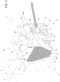
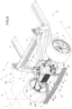
Figure 2 is a perspective view of a frame assembly of the motor vehicle inFigure 1 comprising the suspension attachment structure with parts removed for clarity; -
Figure 2A is a front view on an enlarged scale of a portion of the motor vehicle inFigure 1 ; -
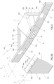
Figure 3 is a perspective view of the suspension attachment structure inFigures 1 ,2 , and2A ; -
Figure 3A is a cross-section according to plane III-III inFigure 3 ; -
Figure 4 is a perspective view of a frame assembly comprising a suspension attachment structure according to a second embodiment of this invention with parts removed for clarity; -
Figure 5 is a perspective view on an enlarged scale of a portion of the frame assembly inFigure 4 ; -
Figure 5A is a detail on a further enlarged scale of the portion of the frame assembly illustrated inFigure 5 ; -
Figure 6 is a perspective view of a frame assembly comprising a suspension attachment structure according to a third embodiment of this invention with parts removed for clarity; -
Figure 7 is a perspective view on an enlarged scale of a portion of the frame assembly inFigure 6 ; and -
Figure 7A is a detail on a further enlarged scale of the portion of the frame assembly illustrated inFigure 7 . - In
Figure 1 , thereference number 1 is used to indicate, as a whole, a motor vehicle comprising: - a
frame 2, - a passenger compartment for housing at least one driver and, potentially, one or more passengers, which is fixed in relation to the
frame 2; - a plurality of
wheels 3, 4 rotatable about respective rotational axes to move theframe 2 with respect to the ground; and - a plurality of suspensions adapted couple the
wheels 3, 4 to theframe 2 at relative distances variable along a direction Z of thevehicle 1, in use, vertical with respect to the ground. - The
motor vehicle 1 also comprises drive means - not illustrated - adapted to rotate thewheels 3, 4 around the respective rotation axes. For example, the drive means comprise one or more electric motors each arranged at arespective wheel 3, 4. - The
vehicle 1 also comprises afront portion 1a and aback portion 1b along a forward direction A of thevehicle 1. Thevehicle 1 also defines a longitudinal direction X in relation to which thefront portion 1a and theback portion 1b are opposite each other. - It is possible to distinguish between a pair of front wheels 3 arranged at the
front portion 1a and a pair ofback wheels 4 arranged at theback portion 1b. The suspensions also comprise front suspensions adapted to couple the front wheels 3 to theframe 2 and back suspensions adapted to couple theback wheels 4 to theframe 2. - Considering a midplane of the
vehicle 1 parallel to the longitudinal direction X, it is also possible to identify aleft portion 1c and aright portion 1d of thevehicle 1 in relation to the forward direction A. More specifically, of the twoback wheels 4, one is arranged at theleft portion 1c and the other is arranged at theright portion 1d. In addition, the back suspensions comprise a left suspension and a right suspension adapted to couple theback wheels 4 to theframe 2 placed, respectively, at theleft portion 1c and theright portion 1d. - The
vehicle 1 also comprises an HVAC system 60 - only schematically illustrated inFigure 1 - for heating, ventilation and/or air conditioning (for example, of the passenger compartment). Specifically, theHVAC system 60 is a system for conditioning the passenger compartment of thevehicle 1 and basically comprises acompressor 61, a condenser, anexpansion valve 62, anevaporator 63, and one ormore pipes 64, which fluidically connect the above-mentioned components to each other and inside of which a fluid flows that undergoes a refrigeration cycle. For example, the fluid is a Freon. - As illustrated in
Figure 2 , theframe 2 comprises twospars 5 arranged transversely to the direction X. Specifically, one of the twospars 5 is arranged at theleft portion 1c and the other is arranged at theright portion 1d. - In the embodiment illustrated, the
spars 5 are parallelepiped-shaped bodies extending mainly along respective directions B and C incident to one another and transversal to the direction X. In addition, thespars 5 are preferably identical to each other and are made of metal. In addition, thespars 5 are arranged symmetrically to the midplane of thevehicle 1 parallel to the longitudinal direction X. - Each
spar 5 comprises a respectiveflat surface 6 on the opposite side to the other of the twospars 5. Theflat surfaces 6 of the twospars 5 converge towards theback portion 1b. - The
vehicle 1 also comprises asuspension attachment structure 10 comprising (Figure 3 ): - a
main body 11 fixed to theframe 2 and adapted to support one or more suspensions; and - a
fluidic path 12 crossed internally by a fluid. - The
fluidic path 12 comprises, in turn: - an
opening 13 for the inlet of the fluid; - an
opening 14 for the outlet of the fluid; and - a
heat exchange portion 15 fluidically interposed between theopenings main body 11 and adapted to be struck by an air flow. - Specifically, the
heat exchange portion 15 comprisesmultiple passages 50, which each fluidically connect opening 13 to opening 14. More specifically, eachpassage 50 defines a cavity inside of which the fluid flows; the surfaces that define eachpassage 50, in addition, are impinged on the outside by the air flow. In detail, thepassages 50 define with one another a plurality ofinterstices 52 adapted to enable the passage of the air flow (Figure 2A ). - The air flow is due to the relative motion between the
vehicle 1 and the atmospheric air in which it is immersed and is adapted to remove heat from the fluid that crosses theheat exchange portion 15. As a result of this heat exchange, thestructure 10 acts as a heat exchanger. - Specifically, the
structure 10 is a heat exchanger of theHVAC system 60, the fluid that crosses thefluidic path 12 is the same fluid that crosses the other components of theHVAC system 60, and thefluidic path 12 is part of thepipes 64. More specifically, thestructure 10 is a condenser of theHVAC system 60. - As illustrated in
Figure 1 , thestructure 10 is arranged at theback portion 1b. In particular, thestructure 10 is interposed between the twoback wheels 4 along a direction Y orthogonal to the directions X and Z. - The
main body 11 is adapted to support both the right and left suspensions of the back suspensions. To this end, themain body 11 comprisesmultiple attachment elements 26 configured to enable the coupling of the suspensions to the main body 11 (Figure 3 ). - The
main body 11 is box shaped and comprises (Figure 3 ) : - a
compartment 20 adapted to house one or more components of thevehicle 1; and - two
openings 21 adapted to allow an air flow to flow into thecompartment 20. - Specifically, the
heat exchange portion 15 faces thecompartment 20 and/or contributes to defining thecompartment 20. - The
main body 11 also comprises: - a
wall 22, at which thestructure 10 is fixed to theframe 2; - a
wall 23opposite wall 22 along the direction X, at which theheat exchange portion 15 is arranged; and - two
lateral walls wall 22 andwall 23 along the direction X. - As illustrated in
Figure 2 , thewall 22 is fixed to each of the twospars 5. Specifically, thesurfaces 6 are adapted to guide the air flow towards thestructure 10 and theheat exchange portion 15. - In addition, the
lateral wall 24 extends on the side of theright portion 1d of thevehicle 1 and thelateral wall 25 extends on the side of theleft portion 1c. Eachlateral wall respective opening 21. - Each
opening 21 has a rectangular or substantially rectangular shape on a plane parallel to the directions X and Z and comprises asurface 27 extending transversal to the longitudinal direction X and adapted to guide and make the air flow converge towards theheat exchange portion 15. In addition, thesurfaces 27 of the twoopenings 21 are symmetrical to each other in relation to a midplane of themain body 11 parallel to the directions X and Z. - Specifically, the
main body 11 comprises theattachment elements 26 at both thelateral walls - As illustrated in
Figure 3 , thewall 22 is flat and perpendicular to the longitudinal direction X; thewall 23 is also flat and parallel to thewall 22. - The
wall 23 comprises, in turn, anopening 28 directed parallel to the direction X and at which theheat exchange portion 15 is housed. Specifically, theheat exchange portion 15 directly faces theopening 28. - In the embodiment illustrated, a cross-section of the
opening 28 on a plane perpendicular to the direction X comprises a rectangular-shapedregion 28a and a trapezoidal-shapedregion 28b joined together. Theregions Figure 3 ). - In addition, the
main body 11 has a tapered shape proceeding from thewall 22 to thewall 23 along the direction X. In detail, eachlateral wall - a
flat region 40 extending along the direction X between therespective opening 21 and thewall 23; and - a
region 41 extending along the direction X between thewall 22 and therespective opening 21 and joining thewall 22 to theflat region 40. - More specifically, each
flat region 40 is perpendicular or substantially perpendicular to thewall 23; eachregion 41 is curved and contributes to guiding the air flow towards therespective opening 21. - The
main body 11 also comprises: - a
wall 30 with an orthogonal base or substantially orthogonal base to the direction Z; and - a
wall 31 opposite thewall 30 along the direction Z and parallel to thewall 30. - In the embodiment illustrated, the
walls openings wall 31. - In detail, the
fluidic path 12 comprises a first section - not illustrated - that extends between theopening 13 and theheat exchange portion 15 inside themain body 11 and a second section - also not illustrated - that extends between theheat exchange portion 15 and theopening 14. The first and the second section are respective hollow portions of themain body 11 extending at thewall 23. - The
heat exchange portion 15 comprises alattice structure 51 comprising structural elements (for example, truss elements) repeated and defining thepassages 50 for the fluid and theinterstices 52 between the above-mentionedpassages 50. Specifically, theinterstices 52 are formed between the outer surfaces of thepassages 50 and are adapted to enable the passage of the air flow from thecompartment 20 through theopening 28. - The
lattice structure 51 extends parallel to the direction X starting from thewall 23 towards thewall 22. - The
lattice structure 51 could comprise, in addition, one or more surfaces with fins. - In detail, the
lattice structure 51 is made using additive manufacturing, for example using selective laser melting of metal powders. - The
passages 50 preferably comprise heat exchange surfaces between the fluid and the air in the form of gyroids. In addition, the fluid inside thepassages 50 is fluidically insulated from the air. - In addition, the
structure 10 is preferably made of aluminium alloy. - The
frame 2 comprises, in addition, astrut 7 adapted to absorb the longitudinal shocks of thevehicle 1, i.e. parallel to the direction X. Thestrut 7 is arranged symmetrically in relation to the midplane of thevehicle 1 parallel to the direction X (Figure 2 ). - Specifically, the
strut 7 is fixed to thestructure 10 on the side of thesurface 23 and comprises anopening 8 at least partially overlapping theopening 28. Theopening 8 is a through opening parallel to the direction X and is adapted to enable the passage of air that impinged theheat exchange portion 15. In more detail, thestrut 7 is made of aluminium and/or a composite material. - The extension of the
opening 8 orthogonally to the longitudinal direction X preferably decreases gradually along the longitudinal direction X in the direction oriented from thefront portion 1a to theback portion 1b. In other words, theopening 8 acts as a nozzle for the air flow coming out of theopening 28. - In the embodiment illustrated, the
strut 7 has a trapezoidal shape on a plane orthogonal to the direction Z. - The
frame 2 also comprises acrossbeam 90 opposite thefront portion 1a with respect to thestructure 10 along the longitudinal direction X. Thecrossbeam 90 extends parallel or substantially parallel to the direction Y and is fixed to thestrut 7 on the side of theopening 8. - The
crossbeam 90 comprises, in turn, anopening 91, adapted to enable the passage of the air that has impinged theheat exchange portion 15 and that crossed theopening 8. Theopening 91 is at least partially aligned with theopening 8 parallel to the direction Y. In addition, theopening 91 is preferably arranged at the midplane of thecrossbeam 90 parallel to the direction Y. - In the embodiment illustrated, the
opening 91 has a rectangular shape. - The
crossbeam 90 also comprises aface 90a turned towards the side of thefront portion 1a and, thus, facing thestructure 10 and aface 90b turned towards the side of theback portion 1b.
Theframe 2 also comprises twospars spars spars spars - The
spar 92 comprises twoends end 92a is fixed to thestrut 7 andend 92b is fixed to thecrossbeam 90. Similarly, thespar 93 comprises twoends end 93a is fixed to thestrut 7 andend 93b is fixed to thecrossbeam 90. More specifically, theends crossbeam 90 on the side of theface 90a (Figure 2 ). - The
spars strut 7. In addition, the distance between theends ends - More specifically, the
spar 92 comprises aface 92c facing thespar 93 and aface 92d opposite theface 92c; thespar 93 comprises aface 93c facing thespar 92 and aface 93d opposite theface 93c. - The
structure 10, thestrut 7, and thespars frame assembly 100 of thevehicle 1, in particular a back frame assembly, i.e. arranged at theback portion 1b. - Advantageously,
structure 10 comprises thermal insulation means 900 adapted to limit heat transfer betweenheat exchange portion 15 and main body 11 (Figure 3A ). - In detail, thermal insulation means 900 are integrated into
main body 11. In further detail, the insulation means 900 are made in a thermal insulating material, e.g. rubber and are arranged close to opening 28 at the same region ofmain body 11 along whichheat exchange portion 15 extends. - As shown in
Figure 3A , insulation means 900 are parallelepiped shaped and have an extension equal or greater than the extension ofheat exchange portion 15 along direction X. Furthermore, insulation means 900 extend both on the side oflateral wall 24, and on the side oflateral wall 25. - In greater detail,
main body 11 comprises acavity 111, wherein the thermal insulation means 900 are housed. - Alternatively or in addition, insulation means 900 are in contact with
main body 11 and outsidemain body 11. - In use, the
structure 10 supports the back suspensions, absorbing the stresses to which they are subject, and thestrut 7 and thespars vehicle 1. - When the
HVAC system 60 is activated, the fluid circulates through the components of the system, undergoing a refrigeration cycle. More specifically, when the fluid reaches thestructure 10, it enters from theopening 13, crosses the first section, theheat exchange portion 15, the second section, and flows out from theopening 14. - At the same time, the air flow is guided by the
spars 5, penetrates thecompartment 20 through theopenings 21, hits theheat exchange portion 15, and flows out from thecompartment 20 through theopening 28. In particular, the air flow flows through theinterstices 52 of thelattice structure 51 and flows out in succession through theopenings - More specifically, when crossing the
heat exchange portion 15, the fluid flows through thepassages 50 and part of its heat is absorbed by the air flow hitting it. When crossing thepassages 50, the fluid preferably passes from the gaseous state to the liquid state. - During operation, thermal insulation means 900 limit heat transfer between
heat exchange portion 15 andmain body 11. - With reference to
Figures 4 ,5 and 5A , reference number 100' indicates a frame assembly according to a second embodiment of the invention. The frame assembly 100' is similar to theframe assembly 100 and will be described below only as far as it differs from the latter; the same or equivalent parts of theframe assemblies 100; 100' will be distinguished, where possible, by the same reference numbers. The frame assembly 100' differs from theframe assembly 100 due to it comprising a crossbeam 90' that comprises, in turn, a fluidic path 120' adapted to be crossed internally by a fluid. - The fluidic path 120' of the crossbeam 90' is fluidically connected to the
fluidic path 12 of thestructure 10 and the fluid that crosses the fluidic path 120' is the same fluid that crosses thefluidic path 12. - In detail, the spars 92' and 93' each comprise one or several pipes 94', 95' (only schematically illustrated in
Figure 5 ) that fluidically connect the fluidic path 120' to thefluidic path 12. In the embodiment illustrated, the pipes 94', 95' each comprise a tubular element for the passage of fluid between the fluidic path 120' and thefluidic path 12. - The fluidic path 120' comprises an inlet and an outlet (not illustrated) for the fluid and a heat exchange portion 150' fluidically interposed between the inlet and the outlet for the fluid and adapted to be hit by an air flow.
- In the embodiment illustrated, the pipe 94' fluidically connects the
fluidic path 12 to the inlet for the fluid of the fluidic path 120' and the pipe 95' fluidically connects the outlet for the fluid of the fluidic path 120' to thefluidic path 12. - Specifically, the heat exchange portion 150' comprises multiple passages 500', which each fluidically connect the inlet to the outlet for the fluid. More specifically, each passage 500' defines a cavity inside of which the fluid flows; the surfaces that define each passage 500', in addition, are impinged on the outside by the air flow. In addition, the passages 500' define with one another a plurality of interstices 520' adapted to enable the passage of the air flow (
Figure 5A ). - In the embodiment illustrated in
Figure 5A , the interstices 520' are at least partially directed parallel to the direction X. - The air flow is due to the relative motion between the vehicle 1' and the atmospheric air in which it is immersed and is adapted to remove heat from the fluid that crosses the heat exchange portion 120'. As a result of this heat exchange, the crossbeam 90' acts as a heat exchanger.
- Specifically, the crossbeam 90' forms, together with the
structure 10, a heat exchanger of theHVAC system 60; the fluid that crosses thefluidic paths 12 and 120' is the same fluid that crosses the other components of theHVAC system 60 and thefluidic paths 12 and 120' are part of thepipes 64. More specifically, the crossbeam 90' and thestructure 10 constitute a condenser of theHVAC system 60. For example, the crossbeam 90' and thestructure 10 are arranged in series or in parallel in theHVAC system 60. - The heat exchange portion 150' comprises a lattice structure 510' comprising structural elements (for example, truss elements) repeated and defining the passages 500' for the fluid and the interstices 520' between the above-mentioned passages 500'. Specifically, the interstices 520' are formed between the outer surfaces of the passages 500' and are adapted to enable the passage of the air flow from the
face 90a' towards theface 90b' (Figure 5A ). - The lattice structure 510' preferably extends parallel to the direction X between the
wall 90a' and thewall 90b'. - The lattice structure 510' could comprise, in addition, one or more surfaces with fins.
- In detail, the lattice structure 510' is made using additive manufacturing, for example using selective laser melting of metal powders.
- The passages 500' preferably comprise heat exchange surfaces between the fluid and the air in the form of gyroids. In addition, the fluid inside the passages 500' is fluidically insulated from the air.
- In addition, the crossbeam 90' is preferably made of aluminium alloy.
- The operation of the frame assembly 100' is similar to the operation of the
frame assembly 100 and is described below only as far as it differs from the latter. - In use, when the
HVAC system 60 is activated, the fluid circulates through the components of the system, undergoing a refrigeration cycle. Specifically, when the fluid reaches thestructure 10, part of the fluid crosses thefluidic path 12 and part of the fluid flows towards the fluidic path 120'. More specifically, the fluid reaches the inlet for the fluid of the fluidic path 120' through the pipe 94', crosses the heat exchange portion 150', passes through the outlet for the fluid of the fluidic path 120' then runs along the pipe 95' towards thestructure 10. - At the same time, an air flow hits the heat exchange portion 150' in the direction oriented by the
face 90a' to theface 90b'. In particular, this air flow flows through the interstices 520' of the lattice structure 510'. - More specifically, when crossing the heat exchange portion 150', the fluid flows through the passages 500' and part of its heat is absorbed by the air flow hitting it.
- With reference to
Figures 6 ,7 and 7A , reference number 100' indicates a frame assembly according to a third embodiment of the invention. The frame assembly 100'' is similar to the frame assembly 100' and will be described below only as far as it differs from the latter; the same or equivalent parts of the frame assembly 100'; 100'' will be distinguished, where possible, by the same reference numbers. The frame assembly 100'' differs from the frame assembly 100' in that thespars 92" and 93" comprise respectivefluidic paths 1200", 1201" suitable for being crossed internally by a fluid and each comprising: - an inlet and an outlet for the fluid; and
- a
heat exchange portion 1500" fluidically interposed between the inlet and the outlet for the fluid and adapted to be struck by an air flow. - The fluidic paths 1200'' and 1201" are fluidically connected to the
fluidic path 12 of thestructure 10 and to the fluidic path 120'' of thecrossbeam 90" and the fluid that crosses thefluidic paths 1200", 1201" is the same fluid that crosses thefluidic path 12 and thefluidic path 120". In detail, thefluidic paths 12 and 120'' are fluidically connected together by means of the fluidic paths 1200'' and 1201" . - Specifically, each heat exchange portion 1500'' comprises multiple passages 5000'', which each fluidically connect the inlet to the outlet for the fluid of the corresponding
fluidic path 1200", 1201". More specifically, eachpassage 5000" defines a cavity inside of which the fluid flows; the surfaces that define each passage 5000'', in addition, are impinged on the outside by the air flow. In detail, the passages 5000'' define with one another a plurality ofinterstices 5200" adapted to enable the passage of the air flow. - In the embodiment illustrated in
Figures 7 and 7A , the interstices 5200'' are at least partially directed parallel to the direction X. - The air flow is due to the relative motion between the
vehicle 1" and the atmospheric air in which it is immersed and is adapted to remove heat from the fluid that crosses theheat exchange portions 1200", 1201". As a result of this heat exchange, thespars 92", 93" act as heat exchangers. - Specifically, the
spars 92", 93" form, together with the crossbeam 90'' and thestructure 10, a heat exchanger of theHVAC system 60; the fluid that crosses thefluidic paths 12, 120'', 1200" and 1201" is the same fluid that crosses the other components of theHVAC system 60 and thefluidic paths 12, 120'', 1200" and 1201" are part of thepipes 64. More specifically, thespars 92", 93", thecrossbeam 90", and thestructure 10 constitute a condenser of theHVAC system 60. For example, thecrossbeam 90", thespars 92", 93'', and thestructure 10 are arranged in series or in parallel in theHVAC system 60. - The
heat exchange portions 1500" comprise alattice structure 5100" comprising structural elements (for example, truss elements) repeated and defining thepassages 5000" for the fluid and theinterstices 5200" between the above-mentionedpassages 5000". Specifically, theinterstices 5200" are formed between the external surfaces of thepassages 5000". More specifically, theinterstices 5200" of thespar 92" are adapted to enable the passage of air flow from theface 92d'' to theface 92c''; theinterstices 5200" of thespar 93" are adapted to enable the passage of the air flow from theface 93d'' to theface 93c". - The lattice structure 5100'' of the spar 92'' preferably extends parallel to the direction X between the
faces 92c" and 92d"; the lattice structure 5100'' of thespar 93" extends parallel to the direction X between thefaces 93c" and 93d". - The
lattice structures 5100" could comprise, in addition, one or more surfaces with fins. - In detail, the
lattice structures 5100" are made using additive manufacturing, for example using selective laser melting of metal powders. - The
passages 5000" comprise heat exchange surfaces between the fluid and the air in the form of gyroids. In addition, the fluid inside thepassages 5000" is fluidically insulated from the air. - In addition, the
spars 92", 93" are preferably made of aluminium alloy. - The operation of the frame assembly 100'' is similar to the operation of the frame assembly 100' and is described below only as far as it differs from the latter.
- In use, when the
HVAC system 60 is activated, the fluid circulates through the components of the system, undergoing a refrigeration cycle. Specifically, when the fluid reaches thestructure 10, part of the fluid crosses thefluidic path 12 and part of the fluid flows towards the fluidic path 120''. More specifically, the fluid reaches the inlet for the fluid of the fluidic path 120'' through thefluidic path 1200", crosses the heat exchange portion 150', passes through the outlet for the fluid of thefluidic path 120" then runs along thefluidic path 1201" towards thestructure 10. - At the same time, an air flow hits at least part of the heat exchange portion 1500'' of the fluidic path 1200'' in the direction oriented by the
face 92d'' to theface 92c'' and/or at least part of the heat exchange portion 1500'' of thefluidic path 1201" in the direction oriented by theface 93d" to theface 93c". In particular, this air flow flows through theinterstices 5200" of thelattice structures 5100". - More specifically, when crossing the
heat exchange portions 1500", the fluid flows through thepassages 5000" and part of its heat is absorbed by the air flow hitting it. - From the above, the advantages of the
structure 10, of theframe assembly 100; 100'; 100", and of themotor vehicle 1; 1'; 1" according to the invention are clear. - In particular, since the
structure 10 comprises themain body 11, to which the suspensions of themotor vehicle 1; 1'; 1" are fixed and thefluidic path 12, at which the cooling fluid exchanges heat with the incident air flow, thestructure 10 performs a structural function and a heat exchanger function at the same time. As a result, it is possible to reduce the number of components needed to implement the thermodynamic cycle of theHVAC cycle 60 and, thus, the weight of themotor vehicle 1; 1'; 1", ensuring, at the same time, the occupants' comfort. - Since the
main body 11 comprises thecompartment 20 and theopenings 21 and theheat exchange portion 15 faces thecompartment 20 or defines thecompartment 20, the air flow is guided towards theheat exchange portion 15 efficiently. The orientation of thesurface 27 additionally contributes to orienting the air flow entering theheat exchange portion 15 to encourage heat exchange with the fluid that flows in thefluidic path 12. - Since the crossbeam 90' comprises the fluidic path 120', which is fluidically connected to the
fluidic path 12, at which the cooling fluid exchanges heat with the incident air flow, the crossbeam 90' performs, at the same time, a structural function and a heat exchanger function. As a result, it is possible to additionally reduce the number of components needed to implement the thermodynamic cycle of theHVAC system 60 and, thus, the weight of the motor vehicle 1', ensuring, at the same time, the occupants' comfort. - The above is even more true for the
vehicle 1", wherein thespars 92" and 93" comprise correspondingfluidic paths 1200", 1201", which also contribute to the heat exchange. - Since
structure 10 comprises the thermal insulation means 900, heat transfer betweenheat exchange portion 15 andmain body 11 may be limited. As a result, undesired heat transfer betweenheat exchange portion 15 and the rest ofmotor vehicle 1 is limited and in particular, towardsframe 2 to whichstructure 10 is fixed. As a matter of fact, the transfer of heat to the frame of the vehicle is generally undesirable during hot weather, due to the temperature rise it may bring about inside the passenger compartment of the motor vehicle. - Finally, it is clear that changes may be made to the
structure 10, theframe assembly 100; 100'; 100'', and themotor vehicle 1; 1'; 1" according to the invention, and variations produced thereto, that, in any case, do not depart from the scope of protection defined by the claims. - In particular, the number and shape of the components described and illustrated could be different to and, in particular, varied with great freedom.
- The
HVAC system 60 could comprise additional components instead of or in addition to those illustrated inFigure 1 and described above. For example, theHVAC system 60 could comprise one or more ventilators, valves, turbines, and/or heat exchangers. Alternatively, the fluid could be water and thestructure 10 and/or the crossbeam 90' and/or thecrossbeam 90" and/or thespars 92", 93" could act as a radiator for themotor vehicle 1. - The
frame assembly 100; 100'; 100" could be a front frame assembly, namely arranged at thefront portion 1a. In particular, thestructure 10 could be placed between the front wheels 3 along the direction Y. - The
frame assembly 100; 100', 100'' may not comprise thestrut 7. According to this embodiment not illustrated, theend 92a; 92a'; 92a" of thespar 92; 92'; 92" is fixed to thestructure 10 and theend 92b; 92b'; 92b" is fixed to thecrossbeam 90; 90'; 90". Similarly, theend 93a; 93a'; 93a' ' of thespar 93; 93'; 93" is fixed to thestructure 10 and theend 93b; 93b'; 93b" is fixed to thecrossbeam 90; 90'; 90". - The
frame assembly 100 could comprise more than onespar 92 and/or more than onespar 93; the frame assembly 100' could comprise more than one spar 92' and/or more than one spar 93'; theframe assembly 100" could comprise more than onespar 92" and/or more than onespar 93". - The frame assembly could comprise a
spar 92 and a spar 93' and/or aspar 93" or could comprise aspar 93 and a spar 92' and/or aspar 92". - Frame assembly 100'; 100" may comprise further thermal insulation means, preferably made in the same material of thermal insulation means 900, and adapted to limit heat transfer between at least one of the following groups of components:
- crossbeam 90'; 90'' and
main body 11; - crossbeam 90'; 90" and
strut 7; - crossbeam 90'; 90'' and spars 92', 93'; 92", 93";
- crossbeam 90'; 90'' and the rest of
frame 2; - spars 92', 93'; 92", 93'' and
main body 11; - spars 92', 93'; 92", 93'' and
strut 7; - spars 92', 93'; 92", 93'' and the rest of
frame 2.
Claims (25)
- A suspension attachment structure (10) for a motor vehicle (1; 1'; 1") comprising:- a main body (11) adapted to be fixed to a frame (2) of said motor vehicle (1; 1'; 1") and adapted to support one or more suspensions of said motor vehicle (1; 1'; 1"); and- a first fluidic path (12) adapted to be crossed, in use, internally by a fluid;said first fluidic path (12) comprising, in turn:- a first opening (13) for the inlet of said fluid;- a second opening (14) for the outlet of said fluid;- a first heat exchange portion (15) fluidly interposed between said first opening (13) and said second opening (14) and supported by and/or integrated with said main body (11);said first heat exchange portion (15) being adapted to be hit, in use, by an air flow.
- The structure according to claim 1, wherein said main body (11) comprises:- a compartment (20) adapted to house at least partially one or more components of said motor vehicle (1; 1'; 1");- at least a third opening (21) adapted to allow, in use, said air flow into said compartment (20);said first heat exchange portion (15) facing said compartment (20) and/or defining said compartment (20).
- The structure according to claim 2, wherein said main body (11) comprises:- a first wall (22), at which said structure (10) is adapted to be fixed to said frame (2);- a second wall (23) opposite to said first wall (22) along a first direction (X);- third lateral walls (24, 25) extending between said first wall (22) and said second wall (23) along said first direction (X);said first heat exchange portion (15) being arranged at said second wall (23); said at least a third opening (21) being arranged at a respective said lateral wall (24, 25).
- The structure according to claim 3, wherein each said third opening (21) comprises a surface (27) extending transversally to said first direction (X) and adapted to guide, in use, said air flow towards said first heat exchange portion (15).
- The structure according to claim 3 or 4, wherein said main body (11) has a tapered shape proceeding from said first wall (22) towards said second wall (23) parallel to said first direction (X).
- The structure according to any one of claims 3 to 5, wherein each said third lateral wall (24, 25) comprises:- a first region (40), which is planar and extending along said first direction (X) between the respective said third opening (21) and said second wall (23); and- a second region (41) extending along said first direction (X) between said first wall (22) and said respective third opening (21) and joining said first wall (22) to said first region (40);each said second region (41) being adapted to guide said air flow through said respective third opening (21).
- The structure according to any one of the preceding claims, wherein said first heat exchange portion (15) comprises a plurality of first passages (50) each fluidly connected to said first opening (13) and said second opening (14) and adapted to be crossed, in use, by said fluid.
- The structure according to claim 7, wherein said first heat exchange portion (15) comprises a first lattice structure (51) comprising said first passages (50) and defining a plurality of first interstices (52) adapted to be crossed, in use, by said air flow.
- The structure according to claim 8, wherein said first lattice structure (51) is made by additive manufacturing.
- The structure according to any one of the preceding claims, comprising thermal insulation means (900) adapted to limit heat transfer between said first heat exchange portion (15) and said main body (110).
- The structure according to claim 10, wherein said thermal insulation means (900) are integrated into said main body (11) or in contact with said main body (11).
- A frame assembly for a motor vehicle (1; 1'; 1") comprising:- at least one structure (10) according to any one of the preceding claims, adapted to be fixed to a frame (2) of said motor vehicle (1; 1'; 1");- at least one crossbeam (90; 90'; 90") extending transversally to a first direction (X);- at least one spar (92, 93; 92', 93'; 92", 93") extending between said structure (10) and said crossbeam (90; 90'; 90'') parallel to said first direction (X).
- The frame assembly according to claim 12, wherein said crossbeam (90'; 90") comprises a second fluidic path (120'; 120") fluidly connected to said first fluidic path (12) ;said second fluidic path (120'; 120") comprising in turn:- a first inlet for said fluid;- a first outlet for said fluid;- a second heat exchange portion (150'; 150") fluidly interposed between said first inlet and said first outlet;said second heat exchange portion (150'; 150") being adapted to be hit, in use, by an air flow.
- The frame assembly according to claim 13, wherein said second heat exchange portion (150'; 150") comprises a plurality of second passages (500', 500"), each fluidly connected to said first inlet and said first outlet and adapted to be crossed, in use, by said fluid.
- The frame assembly according to claim 14, wherein said second heat exchange portion (150'; 150") comprises a second lattice structure (510') comprising said second passages (500') and defining a plurality of second interstices (520') adapted to be crossed, in use, by said air flow.
- The frame assembly according to any one of claims 13 to 15, wherein said at least one spar (92', 93') comprises at least one duct (94, 95') adapted to fluidly connect said second fluidic path (120') to said first fluidic path (12).
- The frame assembly according to any one of claims 13 to 15, wherein said at least one spar (92''; 93") comprises a third fluidic path (1200", 1201") fluidly connected to said first fluidic path (12) and said second fluidic path (120");said third fluidic path (1200", 1201") comprising in turn:- a second inlet for said fluid;- a second outlet for said fluid;- a third heat exchange portion (1500") fluidly interposed between said second inlet and said second outlet;said third heat exchange portion (1500") being adapted to be hit, in use, by an air flow.
- The frame assembly according to claim 17, wherein said third heat exchange portion (1500") comprises a plurality of third passages (5000"), each fluidly connected to said second inlet and said second outlet and adapted to be crossed, in use, by said fluid.
- The frame assembly according to claim 18, wherein said third heat exchange portion (1500") comprises a third lattice structure (5100") comprising said third passages (5000") and defining a plurality of third interstices (5200") adapted to be crossed, in use, by said air flow.
- The frame assembly according to any one of claims 12 to 19, comprising a strut (7) adapted to absorb the shocks of said motor vehicle (1; 1'; 1") directed parallel to said first direction (X);
said at least one spar (92, 93; 92', 93'; 92", 93") being fixed to said strut (7) and to said crossbeam (90; 90'; 90"). - A motor vehicle (1; 1'; 1") comprising:- a frame (2),- a plurality of wheels (3, 4) rotatable about respective rotational axes to move, in use, said frame (2) with respect to the ground;- a plurality of suspensions adapted to couple said wheels (3) to said frame (2) at variable relative distances along a second direction (Z) vertical, in use; and- a structure (10) according to any one of claims 1 to 11, adapted to be fixed to said frame (2) and to which at least one of said suspensions is attached.
- The motor vehicle according to claim 21, wherein said frame (2) comprises two bodies (5) adapted to guide, in use, said air flow towards said structure (10); said bodies (5) extending each parallel to a third direction (B) and a fourth direction (C), respectively; said third direction (B) and said fourth direction (C) being mutually incident and transversal to said first direction (X); said structure (10) being fixed to said bodies (5).
- The motor vehicle according to claim 21 or 22, further comprising a system (60) for ventilation, heating and/or conditioning; said structure (10) being a heat exchanger of said system (60).
- The motor vehicle according to any one of claims 21 to 23, further comprising a frame assembly (100; 100'; 100") according to any one of claims 12 to 20; said frame assembly (100; 100'; 100") comprising said structure (10).
- The motor vehicle according to claims 23 and 24 wherein, when it comprises the frame assembly (100') according to any one of claims 13 to 16 or 20, said crossbeam (90') defines a heat exchanger of said system (60), together with said structure (10); and/or
wherein, when it comprises the frame assembly (100"= according to any one of claims 17 to 20, said crossbeam (90") and said at least one spar (92", 93'') define a heat exchanger of said structure (60), together with said structure (10).
Applications Claiming Priority (2)
| Application Number | Priority Date | Filing Date | Title |
|---|---|---|---|
| IT202300007899 | 2023-04-21 | ||
| IT102023000007914A IT202300007914A1 (en) | 2023-04-21 | 2023-04-21 | HEAT EXCHANGE DEVICE FOR MOTOR VEHICLE AND MOTOR VEHICLE COMPRISING THE SAME |
Publications (1)
| Publication Number | Publication Date |
|---|---|
| EP4454937A1 true EP4454937A1 (en) | 2024-10-30 |
Family
ID=90719344
Family Applications (1)
| Application Number | Title | Priority Date | Filing Date |
|---|---|---|---|
| EP24170446.9A Pending EP4454937A1 (en) | 2023-04-21 | 2024-04-16 | Suspension attachment structure for a motor vehicle and frame assembly for a motor vehicle |
Country Status (2)
| Country | Link |
|---|---|
| US (1) | US20240351399A1 (en) |
| EP (1) | EP4454937A1 (en) |
Families Citing this family (1)
| Publication number | Priority date | Publication date | Assignee | Title |
|---|---|---|---|---|
| US12466485B1 (en) * | 2025-02-27 | 2025-11-11 | Workhorse Group Inc. | Land vehicles incorporating front and rear powertrain units, powertrain units, and components therefor |
Citations (4)
| Publication number | Priority date | Publication date | Assignee | Title |
|---|---|---|---|---|
| DE4032433A1 (en) * | 1990-10-12 | 1992-04-16 | Bayerische Motoren Werke Ag | Axle support beam for motor vehicle - has internal passageways to enable it to function as oil cooler |
| EP0868338A1 (en) * | 1995-12-18 | 1998-10-07 | Francesco Sbarro | Motor vehicle |
| DE19931731A1 (en) * | 1999-07-08 | 2001-01-11 | Rainer Wieland | Motor vehicle with underfloor heat exchanger set underneath internal combustion engine and preferably extending across between front wheels |
| DE102015105601A1 (en) * | 2015-04-13 | 2016-10-13 | Dr. Ing. H.C. F. Porsche Aktiengesellschaft | Rear axle frame for a motor vehicle with an air guide device |
-
2024
- 2024-04-15 US US18/635,317 patent/US20240351399A1/en active Pending
- 2024-04-16 EP EP24170446.9A patent/EP4454937A1/en active Pending
Patent Citations (5)
| Publication number | Priority date | Publication date | Assignee | Title |
|---|---|---|---|---|
| DE4032433A1 (en) * | 1990-10-12 | 1992-04-16 | Bayerische Motoren Werke Ag | Axle support beam for motor vehicle - has internal passageways to enable it to function as oil cooler |
| EP0868338A1 (en) * | 1995-12-18 | 1998-10-07 | Francesco Sbarro | Motor vehicle |
| EP0868338B1 (en) * | 1995-12-18 | 1999-06-16 | Francesco Sbarro | Motor vehicle |
| DE19931731A1 (en) * | 1999-07-08 | 2001-01-11 | Rainer Wieland | Motor vehicle with underfloor heat exchanger set underneath internal combustion engine and preferably extending across between front wheels |
| DE102015105601A1 (en) * | 2015-04-13 | 2016-10-13 | Dr. Ing. H.C. F. Porsche Aktiengesellschaft | Rear axle frame for a motor vehicle with an air guide device |
Also Published As
| Publication number | Publication date |
|---|---|
| US20240351399A1 (en) | 2024-10-24 |
Similar Documents
| Publication | Publication Date | Title |
|---|---|---|
| CN104884892B (en) | Heat exchanger | |
| US9410745B2 (en) | Heat exchanger | |
| JP6216113B2 (en) | Heat exchanger and heat pump system using the same | |
| JP2000203250A (en) | Heat exchanger | |
| JPH116693A (en) | Heat exchanger for vehicle air conditioning | |
| CN104781627A (en) | Heat exchanger | |
| JP6638169B2 (en) | Vehicle air conditioner | |
| EP4454937A1 (en) | Suspension attachment structure for a motor vehicle and frame assembly for a motor vehicle | |
| US20160347146A1 (en) | Storage evaporator having phase change material for use in vehicle air conditioning system | |
| WO2007099868A1 (en) | Heat exchanger and integrated-type heat exchanger | |
| EP0754579B1 (en) | Heat exchanging apparatus for a vehicle | |
| JP5264442B2 (en) | Air conditioner for vehicles | |
| KR102896180B1 (en) | Variable assembly type heat exchanger | |
| JP3811254B2 (en) | Air conditioner for vehicles | |
| JP2015517646A (en) | Air heater spacer and related air heater | |
| CN118810333A (en) | Suspension attachment structure for a motor vehicle and frame assembly for a motor vehicle | |
| CN110849171A (en) | Assembly comprising a heat exchanger and a mount on which said exchanger is mounted | |
| KR102692196B1 (en) | Air conditioning system for vehicle | |
| CN107107712A (en) | Air conditioner for vehicles | |
| KR101173312B1 (en) | Cover Structure of Heater Core Pipe for an Air Conditioning System of a Car | |
| KR100630319B1 (en) | Manifold for Stacked Heat Exchangers | |
| CN221464378U (en) | Heat exchanger, air conditioning box and car | |
| JP2013001252A (en) | Dehumidifying apparatus | |
| US20240278635A1 (en) | Front frame assembly equipped with an integrated radiator and motor vehicle comprising the same | |
| JP6992393B2 (en) | Shutter device and manufacturing method of shutter device |
Legal Events
| Date | Code | Title | Description |
|---|---|---|---|
| PUAI | Public reference made under article 153(3) epc to a published international application that has entered the european phase |
Free format text: ORIGINAL CODE: 0009012 |
|
| STAA | Information on the status of an ep patent application or granted ep patent |
Free format text: STATUS: THE APPLICATION HAS BEEN PUBLISHED |
|
| AK | Designated contracting states |
Kind code of ref document: A1 Designated state(s): AL AT BE BG CH CY CZ DE DK EE ES FI FR GB GR HR HU IE IS IT LI LT LU LV MC ME MK MT NL NO PL PT RO RS SE SI SK SM TR |
|
| STAA | Information on the status of an ep patent application or granted ep patent |
Free format text: STATUS: REQUEST FOR EXAMINATION WAS MADE |
|
| 17P | Request for examination filed |
Effective date: 20250430 |
|
| GRAP | Despatch of communication of intention to grant a patent |
Free format text: ORIGINAL CODE: EPIDOSNIGR1 |
|
| STAA | Information on the status of an ep patent application or granted ep patent |
Free format text: STATUS: GRANT OF PATENT IS INTENDED |