EP4454917A1 - Electric work vehicle - Google Patents
Electric work vehicle Download PDFInfo
- Publication number
- EP4454917A1 EP4454917A1 EP22910923.6A EP22910923A EP4454917A1 EP 4454917 A1 EP4454917 A1 EP 4454917A1 EP 22910923 A EP22910923 A EP 22910923A EP 4454917 A1 EP4454917 A1 EP 4454917A1
- Authority
- EP
- European Patent Office
- Prior art keywords
- housing case
- battery
- support member
- coupling parts
- work vehicle
- Prior art date
- Legal status (The legal status is an assumption and is not a legal conclusion. Google has not performed a legal analysis and makes no representation as to the accuracy of the status listed.)
- Pending
Links
Images






Classifications
-
- B—PERFORMING OPERATIONS; TRANSPORTING
- B60—VEHICLES IN GENERAL
- B60L—PROPULSION OF ELECTRICALLY-PROPELLED VEHICLES; SUPPLYING ELECTRIC POWER FOR AUXILIARY EQUIPMENT OF ELECTRICALLY-PROPELLED VEHICLES; ELECTRODYNAMIC BRAKE SYSTEMS FOR VEHICLES IN GENERAL; MAGNETIC SUSPENSION OR LEVITATION FOR VEHICLES; MONITORING OPERATING VARIABLES OF ELECTRICALLY-PROPELLED VEHICLES; ELECTRIC SAFETY DEVICES FOR ELECTRICALLY-PROPELLED VEHICLES
- B60L50/00—Electric propulsion with power supplied within the vehicle
- B60L50/50—Electric propulsion with power supplied within the vehicle using propulsion power supplied by batteries or fuel cells
- B60L50/60—Electric propulsion with power supplied within the vehicle using propulsion power supplied by batteries or fuel cells using power supplied by batteries
- B60L50/64—Constructional details of batteries specially adapted for electric vehicles
-
- B—PERFORMING OPERATIONS; TRANSPORTING
- B60—VEHICLES IN GENERAL
- B60K—ARRANGEMENT OR MOUNTING OF PROPULSION UNITS OR OF TRANSMISSIONS IN VEHICLES; ARRANGEMENT OR MOUNTING OF PLURAL DIVERSE PRIME-MOVERS IN VEHICLES; AUXILIARY DRIVES FOR VEHICLES; INSTRUMENTATION OR DASHBOARDS FOR VEHICLES; ARRANGEMENTS IN CONNECTION WITH COOLING, AIR INTAKE, GAS EXHAUST OR FUEL SUPPLY OF PROPULSION UNITS IN VEHICLES
- B60K1/00—Arrangement or mounting of electrical propulsion units
- B60K1/04—Arrangement or mounting of electrical propulsion units of the electric storage means for propulsion
-
- B—PERFORMING OPERATIONS; TRANSPORTING
- B60—VEHICLES IN GENERAL
- B60L—PROPULSION OF ELECTRICALLY-PROPELLED VEHICLES; SUPPLYING ELECTRIC POWER FOR AUXILIARY EQUIPMENT OF ELECTRICALLY-PROPELLED VEHICLES; ELECTRODYNAMIC BRAKE SYSTEMS FOR VEHICLES IN GENERAL; MAGNETIC SUSPENSION OR LEVITATION FOR VEHICLES; MONITORING OPERATING VARIABLES OF ELECTRICALLY-PROPELLED VEHICLES; ELECTRIC SAFETY DEVICES FOR ELECTRICALLY-PROPELLED VEHICLES
- B60L1/00—Supplying electric power to auxiliary equipment of vehicles
- B60L1/003—Supplying electric power to auxiliary equipment of vehicles to auxiliary motors, e.g. for pumps, compressors
-
- B—PERFORMING OPERATIONS; TRANSPORTING
- B60—VEHICLES IN GENERAL
- B60L—PROPULSION OF ELECTRICALLY-PROPELLED VEHICLES; SUPPLYING ELECTRIC POWER FOR AUXILIARY EQUIPMENT OF ELECTRICALLY-PROPELLED VEHICLES; ELECTRODYNAMIC BRAKE SYSTEMS FOR VEHICLES IN GENERAL; MAGNETIC SUSPENSION OR LEVITATION FOR VEHICLES; MONITORING OPERATING VARIABLES OF ELECTRICALLY-PROPELLED VEHICLES; ELECTRIC SAFETY DEVICES FOR ELECTRICALLY-PROPELLED VEHICLES
- B60L3/00—Electric devices on electrically-propelled vehicles for safety purposes; Monitoring operating variables, e.g. speed, deceleration or energy consumption
- B60L3/0023—Detecting, eliminating, remedying or compensating for drive train abnormalities, e.g. failures within the drive train
- B60L3/0046—Detecting, eliminating, remedying or compensating for drive train abnormalities, e.g. failures within the drive train relating to electric energy storage systems, e.g. batteries or capacitors
-
- B—PERFORMING OPERATIONS; TRANSPORTING
- B60—VEHICLES IN GENERAL
- B60L—PROPULSION OF ELECTRICALLY-PROPELLED VEHICLES; SUPPLYING ELECTRIC POWER FOR AUXILIARY EQUIPMENT OF ELECTRICALLY-PROPELLED VEHICLES; ELECTRODYNAMIC BRAKE SYSTEMS FOR VEHICLES IN GENERAL; MAGNETIC SUSPENSION OR LEVITATION FOR VEHICLES; MONITORING OPERATING VARIABLES OF ELECTRICALLY-PROPELLED VEHICLES; ELECTRIC SAFETY DEVICES FOR ELECTRICALLY-PROPELLED VEHICLES
- B60L50/00—Electric propulsion with power supplied within the vehicle
- B60L50/50—Electric propulsion with power supplied within the vehicle using propulsion power supplied by batteries or fuel cells
- B60L50/60—Electric propulsion with power supplied within the vehicle using propulsion power supplied by batteries or fuel cells using power supplied by batteries
-
- B—PERFORMING OPERATIONS; TRANSPORTING
- B60—VEHICLES IN GENERAL
- B60L—PROPULSION OF ELECTRICALLY-PROPELLED VEHICLES; SUPPLYING ELECTRIC POWER FOR AUXILIARY EQUIPMENT OF ELECTRICALLY-PROPELLED VEHICLES; ELECTRODYNAMIC BRAKE SYSTEMS FOR VEHICLES IN GENERAL; MAGNETIC SUSPENSION OR LEVITATION FOR VEHICLES; MONITORING OPERATING VARIABLES OF ELECTRICALLY-PROPELLED VEHICLES; ELECTRIC SAFETY DEVICES FOR ELECTRICALLY-PROPELLED VEHICLES
- B60L50/00—Electric propulsion with power supplied within the vehicle
- B60L50/50—Electric propulsion with power supplied within the vehicle using propulsion power supplied by batteries or fuel cells
- B60L50/60—Electric propulsion with power supplied within the vehicle using propulsion power supplied by batteries or fuel cells using power supplied by batteries
- B60L50/66—Arrangements of batteries
-
- B—PERFORMING OPERATIONS; TRANSPORTING
- B60—VEHICLES IN GENERAL
- B60L—PROPULSION OF ELECTRICALLY-PROPELLED VEHICLES; SUPPLYING ELECTRIC POWER FOR AUXILIARY EQUIPMENT OF ELECTRICALLY-PROPELLED VEHICLES; ELECTRODYNAMIC BRAKE SYSTEMS FOR VEHICLES IN GENERAL; MAGNETIC SUSPENSION OR LEVITATION FOR VEHICLES; MONITORING OPERATING VARIABLES OF ELECTRICALLY-PROPELLED VEHICLES; ELECTRIC SAFETY DEVICES FOR ELECTRICALLY-PROPELLED VEHICLES
- B60L53/00—Methods of charging batteries, specially adapted for electric vehicles; Charging stations or on-board charging equipment therefor; Exchange of energy storage elements in electric vehicles
- B60L53/80—Exchanging energy storage elements, e.g. removable batteries
-
- B—PERFORMING OPERATIONS; TRANSPORTING
- B60—VEHICLES IN GENERAL
- B60L—PROPULSION OF ELECTRICALLY-PROPELLED VEHICLES; SUPPLYING ELECTRIC POWER FOR AUXILIARY EQUIPMENT OF ELECTRICALLY-PROPELLED VEHICLES; ELECTRODYNAMIC BRAKE SYSTEMS FOR VEHICLES IN GENERAL; MAGNETIC SUSPENSION OR LEVITATION FOR VEHICLES; MONITORING OPERATING VARIABLES OF ELECTRICALLY-PROPELLED VEHICLES; ELECTRIC SAFETY DEVICES FOR ELECTRICALLY-PROPELLED VEHICLES
- B60L58/00—Methods or circuit arrangements for monitoring or controlling batteries or fuel cells, specially adapted for electric vehicles
- B60L58/10—Methods or circuit arrangements for monitoring or controlling batteries or fuel cells, specially adapted for electric vehicles for monitoring or controlling batteries
-
- B—PERFORMING OPERATIONS; TRANSPORTING
- B60—VEHICLES IN GENERAL
- B60L—PROPULSION OF ELECTRICALLY-PROPELLED VEHICLES; SUPPLYING ELECTRIC POWER FOR AUXILIARY EQUIPMENT OF ELECTRICALLY-PROPELLED VEHICLES; ELECTRODYNAMIC BRAKE SYSTEMS FOR VEHICLES IN GENERAL; MAGNETIC SUSPENSION OR LEVITATION FOR VEHICLES; MONITORING OPERATING VARIABLES OF ELECTRICALLY-PROPELLED VEHICLES; ELECTRIC SAFETY DEVICES FOR ELECTRICALLY-PROPELLED VEHICLES
- B60L58/00—Methods or circuit arrangements for monitoring or controlling batteries or fuel cells, specially adapted for electric vehicles
- B60L58/10—Methods or circuit arrangements for monitoring or controlling batteries or fuel cells, specially adapted for electric vehicles for monitoring or controlling batteries
- B60L58/18—Methods or circuit arrangements for monitoring or controlling batteries or fuel cells, specially adapted for electric vehicles for monitoring or controlling batteries of two or more battery modules
- B60L58/21—Methods or circuit arrangements for monitoring or controlling batteries or fuel cells, specially adapted for electric vehicles for monitoring or controlling batteries of two or more battery modules having the same nominal voltage
-
- B—PERFORMING OPERATIONS; TRANSPORTING
- B60—VEHICLES IN GENERAL
- B60L—PROPULSION OF ELECTRICALLY-PROPELLED VEHICLES; SUPPLYING ELECTRIC POWER FOR AUXILIARY EQUIPMENT OF ELECTRICALLY-PROPELLED VEHICLES; ELECTRODYNAMIC BRAKE SYSTEMS FOR VEHICLES IN GENERAL; MAGNETIC SUSPENSION OR LEVITATION FOR VEHICLES; MONITORING OPERATING VARIABLES OF ELECTRICALLY-PROPELLED VEHICLES; ELECTRIC SAFETY DEVICES FOR ELECTRICALLY-PROPELLED VEHICLES
- B60L58/00—Methods or circuit arrangements for monitoring or controlling batteries or fuel cells, specially adapted for electric vehicles
- B60L58/10—Methods or circuit arrangements for monitoring or controlling batteries or fuel cells, specially adapted for electric vehicles for monitoring or controlling batteries
- B60L58/24—Methods or circuit arrangements for monitoring or controlling batteries or fuel cells, specially adapted for electric vehicles for monitoring or controlling batteries for controlling the temperature of batteries
- B60L58/26—Methods or circuit arrangements for monitoring or controlling batteries or fuel cells, specially adapted for electric vehicles for monitoring or controlling batteries for controlling the temperature of batteries by cooling
-
- B—PERFORMING OPERATIONS; TRANSPORTING
- B60—VEHICLES IN GENERAL
- B60L—PROPULSION OF ELECTRICALLY-PROPELLED VEHICLES; SUPPLYING ELECTRIC POWER FOR AUXILIARY EQUIPMENT OF ELECTRICALLY-PROPELLED VEHICLES; ELECTRODYNAMIC BRAKE SYSTEMS FOR VEHICLES IN GENERAL; MAGNETIC SUSPENSION OR LEVITATION FOR VEHICLES; MONITORING OPERATING VARIABLES OF ELECTRICALLY-PROPELLED VEHICLES; ELECTRIC SAFETY DEVICES FOR ELECTRICALLY-PROPELLED VEHICLES
- B60L9/00—Electric propulsion with power supply external to the vehicle
- B60L9/16—Electric propulsion with power supply external to the vehicle using AC induction motors
- B60L9/18—Electric propulsion with power supply external to the vehicle using AC induction motors fed from DC supply lines
-
- H—ELECTRICITY
- H01—ELECTRIC ELEMENTS
- H01M—PROCESSES OR MEANS, e.g. BATTERIES, FOR THE DIRECT CONVERSION OF CHEMICAL ENERGY INTO ELECTRICAL ENERGY
- H01M10/00—Secondary cells; Manufacture thereof
- H01M10/60—Heating or cooling; Temperature control
- H01M10/61—Types of temperature control
- H01M10/613—Cooling or keeping cold
-
- H—ELECTRICITY
- H01—ELECTRIC ELEMENTS
- H01M—PROCESSES OR MEANS, e.g. BATTERIES, FOR THE DIRECT CONVERSION OF CHEMICAL ENERGY INTO ELECTRICAL ENERGY
- H01M10/00—Secondary cells; Manufacture thereof
- H01M10/60—Heating or cooling; Temperature control
- H01M10/62—Heating or cooling; Temperature control specially adapted for specific applications
- H01M10/625—Vehicles
-
- H—ELECTRICITY
- H01—ELECTRIC ELEMENTS
- H01M—PROCESSES OR MEANS, e.g. BATTERIES, FOR THE DIRECT CONVERSION OF CHEMICAL ENERGY INTO ELECTRICAL ENERGY
- H01M10/00—Secondary cells; Manufacture thereof
- H01M10/60—Heating or cooling; Temperature control
- H01M10/65—Means for temperature control structurally associated with the cells
- H01M10/656—Means for temperature control structurally associated with the cells characterised by the type of heat-exchange fluid
- H01M10/6561—Gases
- H01M10/6563—Gases with forced flow, e.g. by blowers
-
- H—ELECTRICITY
- H01—ELECTRIC ELEMENTS
- H01M—PROCESSES OR MEANS, e.g. BATTERIES, FOR THE DIRECT CONVERSION OF CHEMICAL ENERGY INTO ELECTRICAL ENERGY
- H01M50/00—Constructional details or processes of manufacture of the non-active parts of electrochemical cells other than fuel cells, e.g. hybrid cells
- H01M50/20—Mountings; Secondary casings or frames; Racks, modules or packs; Suspension devices; Shock absorbers; Transport or carrying devices; Holders
- H01M50/204—Racks, modules or packs for multiple batteries or multiple cells
-
- H—ELECTRICITY
- H01—ELECTRIC ELEMENTS
- H01M—PROCESSES OR MEANS, e.g. BATTERIES, FOR THE DIRECT CONVERSION OF CHEMICAL ENERGY INTO ELECTRICAL ENERGY
- H01M50/00—Constructional details or processes of manufacture of the non-active parts of electrochemical cells other than fuel cells, e.g. hybrid cells
- H01M50/20—Mountings; Secondary casings or frames; Racks, modules or packs; Suspension devices; Shock absorbers; Transport or carrying devices; Holders
- H01M50/244—Secondary casings; Racks; Suspension devices; Carrying devices; Holders characterised by their mounting method
-
- H—ELECTRICITY
- H01—ELECTRIC ELEMENTS
- H01M—PROCESSES OR MEANS, e.g. BATTERIES, FOR THE DIRECT CONVERSION OF CHEMICAL ENERGY INTO ELECTRICAL ENERGY
- H01M50/00—Constructional details or processes of manufacture of the non-active parts of electrochemical cells other than fuel cells, e.g. hybrid cells
- H01M50/20—Mountings; Secondary casings or frames; Racks, modules or packs; Suspension devices; Shock absorbers; Transport or carrying devices; Holders
- H01M50/249—Mountings; Secondary casings or frames; Racks, modules or packs; Suspension devices; Shock absorbers; Transport or carrying devices; Holders specially adapted for aircraft or vehicles, e.g. cars or trains
-
- H—ELECTRICITY
- H01—ELECTRIC ELEMENTS
- H01M—PROCESSES OR MEANS, e.g. BATTERIES, FOR THE DIRECT CONVERSION OF CHEMICAL ENERGY INTO ELECTRICAL ENERGY
- H01M50/00—Constructional details or processes of manufacture of the non-active parts of electrochemical cells other than fuel cells, e.g. hybrid cells
- H01M50/20—Mountings; Secondary casings or frames; Racks, modules or packs; Suspension devices; Shock absorbers; Transport or carrying devices; Holders
- H01M50/262—Mountings; Secondary casings or frames; Racks, modules or packs; Suspension devices; Shock absorbers; Transport or carrying devices; Holders with fastening means, e.g. locks
-
- H—ELECTRICITY
- H02—GENERATION; CONVERSION OR DISTRIBUTION OF ELECTRIC POWER
- H02M—APPARATUS FOR CONVERSION BETWEEN AC AND AC, BETWEEN AC AND DC, OR BETWEEN DC AND DC, AND FOR USE WITH MAINS OR SIMILAR POWER SUPPLY SYSTEMS; CONVERSION OF DC OR AC INPUT POWER INTO SURGE OUTPUT POWER; CONTROL OR REGULATION THEREOF
- H02M7/00—Conversion of AC power input into DC power output; Conversion of DC power input into AC power output
- H02M7/42—Conversion of DC power input into AC power output without possibility of reversal
- H02M7/44—Conversion of DC power input into AC power output without possibility of reversal by static converters
- H02M7/48—Conversion of DC power input into AC power output without possibility of reversal by static converters using discharge tubes with control electrode or semiconductor devices with control electrode
-
- B—PERFORMING OPERATIONS; TRANSPORTING
- B60—VEHICLES IN GENERAL
- B60L—PROPULSION OF ELECTRICALLY-PROPELLED VEHICLES; SUPPLYING ELECTRIC POWER FOR AUXILIARY EQUIPMENT OF ELECTRICALLY-PROPELLED VEHICLES; ELECTRODYNAMIC BRAKE SYSTEMS FOR VEHICLES IN GENERAL; MAGNETIC SUSPENSION OR LEVITATION FOR VEHICLES; MONITORING OPERATING VARIABLES OF ELECTRICALLY-PROPELLED VEHICLES; ELECTRIC SAFETY DEVICES FOR ELECTRICALLY-PROPELLED VEHICLES
- B60L2200/00—Type of vehicles
- B60L2200/40—Working vehicles
-
- B—PERFORMING OPERATIONS; TRANSPORTING
- B60—VEHICLES IN GENERAL
- B60L—PROPULSION OF ELECTRICALLY-PROPELLED VEHICLES; SUPPLYING ELECTRIC POWER FOR AUXILIARY EQUIPMENT OF ELECTRICALLY-PROPELLED VEHICLES; ELECTRODYNAMIC BRAKE SYSTEMS FOR VEHICLES IN GENERAL; MAGNETIC SUSPENSION OR LEVITATION FOR VEHICLES; MONITORING OPERATING VARIABLES OF ELECTRICALLY-PROPELLED VEHICLES; ELECTRIC SAFETY DEVICES FOR ELECTRICALLY-PROPELLED VEHICLES
- B60L2240/00—Control parameters of input or output; Target parameters
- B60L2240/10—Vehicle control parameters
- B60L2240/12—Speed
-
- B—PERFORMING OPERATIONS; TRANSPORTING
- B60—VEHICLES IN GENERAL
- B60L—PROPULSION OF ELECTRICALLY-PROPELLED VEHICLES; SUPPLYING ELECTRIC POWER FOR AUXILIARY EQUIPMENT OF ELECTRICALLY-PROPELLED VEHICLES; ELECTRODYNAMIC BRAKE SYSTEMS FOR VEHICLES IN GENERAL; MAGNETIC SUSPENSION OR LEVITATION FOR VEHICLES; MONITORING OPERATING VARIABLES OF ELECTRICALLY-PROPELLED VEHICLES; ELECTRIC SAFETY DEVICES FOR ELECTRICALLY-PROPELLED VEHICLES
- B60L2240/00—Control parameters of input or output; Target parameters
- B60L2240/40—Drive Train control parameters
- B60L2240/54—Drive Train control parameters related to batteries
- B60L2240/545—Temperature
-
- H—ELECTRICITY
- H01—ELECTRIC ELEMENTS
- H01M—PROCESSES OR MEANS, e.g. BATTERIES, FOR THE DIRECT CONVERSION OF CHEMICAL ENERGY INTO ELECTRICAL ENERGY
- H01M2220/00—Batteries for particular applications
- H01M2220/20—Batteries in motive systems, e.g. vehicle, ship, plane
Definitions
- the present invention relates to an electric work vehicle configured such that a travel device is driven by a motor.
- the present invention also relates to, in an electric work vehicle that includes a battery, a motor driven by power supplied from the battery, and a travel device driven by the motor, a configuration for cooling the battery.
- the present invention also relates to, in an electric work vehicle that includes a battery, a motor driven by power supplied from the battery, and a travel device driven by the motor, a configuration of the battery.
- some electric work vehicles include a battery and an inverter supplied with power from the battery and have a configuration in which a motor is driven by power supplied from the inverter.
- some electric work vehicles of an air-cooling type include a cooling fan provided outside of a battery installed in a body, so that an air flow is generated outside of the battery by the cooling fan to cool the battery.
- some electric work vehicles have a configuration in which the entirety of a battery is constituted by stacks with a plurality of battery modules coupled to each other, and the stacks are lined up adjacent to each other and are housed in a housing case.
- Such an electric work vehicle as described above may be provided with a pre-charge part and a discharge part.
- the pre-charge part performs processing for gradually supplying power to the inverter at a start of power supply from the battery to the inverter.
- the discharge part performs processing for discharging power remaining in the inverter.
- the present invention aims to realize a configuration of an electric work vehicle in which a pre-charge part and a discharge part are provided in a compact manner.
- the present invention aims to realize a configuration of an electric work vehicle in which the inner side of a battery is efficiently cooled by air.
- the present invention aims to realize a configuration of an electric work vehicle in which the vibration of stacks (battery modules) against a housing case is suppressed.
- the present invention is directed to an electric work vehicle comprising: a battery; an inverter configured to be supplied with power from the battery; a motor configured to be driven by power from the inverter; and a travel device configured to be driven by the motor,
- the battery when the battery includes the housing case in which the plurality of battery modules are housed, since the pre-charge part and the discharge part are provided in the housing case, the battery realizes a compact layout of the housing case in which the plurality of battery modules are housed, the pre-charge part, and the discharge part. This is advantageous in terms of simplification of the structure.
- the present invention there is no need of providing the pre-charge part and the discharge part at positions separate from the battery, which is also advantageous in terms of saving a space near the battery in the electric work vehicle.
- the pre-charge part and the discharge part are provided in an upper portion of the housing case.
- the pre-charge part and the discharge part are provided in an upper portion of the housing case, heat generated in the pre-charge part and the discharge part easily escapes upward, which is advantageous in terms of the heat dissipation of the battery.
- the pre-charge part and the discharge part are provided at a rear end of the housing case.
- the pre-charge part and the discharge part are provided at the upper rear end of the housing case, and heat generated in the pre-charge part and the discharge part easily escapes upward and rearward, which is advantageous in terms of the heat dissipation of the battery.
- the housing case is quadrangle-shaped when viewed in a plan view, and the pre-charge part and the discharge part are provided in a right or left corner at the rear end of the housing case.
- the pre-charge part and the discharge part are provided in a right or left corner at the upper rear end of the housing case, and heat generated in the pre-charge part and the discharge part easily escapes upward, rearward, and sideward, which is advantageous in terms of the heat dissipation of the battery.
- the housing case includes, on a top thereof, a housing cover covering the pre-charge part and the discharge part.
- the housing cover covering the pre-charge part and the discharge part is provided in an upper portion of the housing case, the pre-charge part and the discharge part are protected, which is advantageous in terms of preventing damage to the pre-charge part and the discharge part.
- the present invention is directed to an electric work vehicle comprising: a battery; a motor configured to be driven by power from the battery; and a travel device configured to be driven by the motor, wherein the battery includes:
- the stack in which a plurality of battery modules are coupled to each other is included in the battery, and a plurality of the stacks are housed in the housing case.
- the plurality of stacks are housed in the housing case while being lined up adjacent to each other at a predetermined gap, and thus air easily flows through the gap between adjacent stacks.
- the fan device is provided, and the ventilation hole of the fan device is formed on the outer side of the housing case at a position facing the gap between adjacent stacks, so that the ventilation hole is close to the gap between the adjacent stacks.
- the housing case includes an opening through which air is passable, the opening being provided at a position facing a terminal of the battery modules.
- the opening is provided at a position facing the terminal of the battery module of the housing case, air outside the housing case is passed through the opening of the housing case and is introduced into the housing case while passing by the terminal of the battery modules, allowing the terminal of the battery modules to be efficiently cooled. This is advantageous in terms of cooling the interior of the battery.
- the opening is provided at a position facing the terminal of the battery modules of the housing case, air in the housing case is passed by the terminal of the battery module and is pushed out to the outside of the housing case through the opening in the housing case, allowing the terminal of the battery modules to be efficiently cooled. This is advantageous in terms of cooling the interior of the battery.
- the plurality of battery modules are coupled to each other while being lined up adjacent to each other to constitute the stack, and adjacent stacks are provided in a manner such that terminals of the plurality of battery modules in one stack and terminals of the plurality of battery modules in another stack face each other with the gap.
- the battery modules of the adjacent stacks face the gaps.
- the battery modules of the adjacent stacks are efficiently cooled with less imbalance, which is advantageous in terms of cooling the interior of the battery.
- the plurality of stacks are lined up in a horizontal direction, and the ventilation hole is provided at a position facing an upper portion of the gap.
- the plurality of stacks are lined up in the horizontal direction and the gap between adjacent stacks extend along the up-down direction, hot air in the gap easily rises upward of the gap.
- the ventilation hole of the fan device is provided at a position facing an upper portion of the gap, the ventilation hole of the fan device is located close to hot air gathering in the upper portion of the gap between adjacent stacks, and air is directly sucked (supplied) by the fan device, which is advantageous in terms of cooling the interior of the battery.
- the electric work vehicle includes a housing cover covering the fan device and an upper portion of the housing case.
- the housing cover covering the fan device and the upper portion of the housing is provided, the fan device is protected, which is advantageous in terms of preventing damage to the fan device.
- the housing cover includes an opening through which air is passable at a position facing a blowing direction or a sucking direction of the fan device.
- the opening in the housing cover is provided while facing the blowing direction of the fan device, when air in the gap between adjacent stacks is sucked by the fan device, air blown from the fan device easily flows out from the housing cover through the opening in the housing cover, which is advantageous in terms of cooling the interior of the battery.
- the opening in the housing cover is provided while facing the sucking direction of the fan device, when air is supplied to the gap between adjacent stacks by the fan device, air outside the housing cover is easily introduced into the housing cover via the opening in the housing cover, which is advantageous in terms of cooling the interior of the battery.
- the fan device is configured to be able to suck air in the housing case
- a case is assumed in which, for example, three stacks are lined up with a gap, a fan device that corresponds to the gap between the central stack and one stack, and a fan device that corresponds to the gap between the central stack and the other stack are provided, and the fan devices are configured to be able to suck air in the housing case.
- air blown from one fan device and air blown from the other fan device flow in opposite directions so that they move away from each other, and thus air blown from the one fan device and the other fan device hardly gather at one position, which is advantageous in terms of cooling the interior of the battery.
- the electric work vehicle further includes:
- a cover member is in front of the driving section in which an operator rides and performs driving, and the battery is housed in the cover member.
- an introduction section through which external air is introduced is provided in a front portion of the cover member, and as the electric work vehicle moves forward, air outside the cover member may be introduced into the cover member from the introduction section of the cover member and may be supplied to the outside of the battery.
- a configuration is also possible in which the top face of the cover member is formed in a forward-descending shape in which it descends toward the front side, and a field of front vision from the driving section is ensured.
- the housing cover covering upper portions of the fan device and the housing is provided, the fan device is protected, which is advantageous in terms of preventing damage to the fan device.
- the top face of the housing cover is formed in a forward-descending shape in which it descends toward a front side, and the top face of the housing cover and the top face of the cover member are arranged at a predetermined distance in the up-down direction, the cross-sectional area of a space between the top face of the housing cover and the top face of the cover member hardly varies from the front end of the housing cover to the rear end of the housing cover.
- the air when, as the electric work vehicle moves forward, air outside the cover member is introduced into the cover member from the introduction section of the cover member and enters the space between the top face of the housing cover and the top face of the cover member, the air easily flow to the rear side without accumulating in the space between the top face of the housing cover and the top face of the cover member.
- the present invention is directed to an electric work vehicle comprising: a battery; a motor configured to be driven by power from the battery; and a travel device configured to be driven by the motor,
- the plurality of lower support members are provided in the housing case of the battery, lower portions of the battery modules are coupled to the lower support members, and lower portions of the stacks are supported by the lower support members.
- Each of the lower support members includes a plurality of coupling parts that protrude outward and are lined up at a predetermined distance, and the first lower frame disposed along a space between adjacent lower support members.
- adjacent lower support members are arranged in a manner such that the coupling parts of one lower support member enter the respective spaces between the coupling parts of the other lower support member, and the coupling parts of the other lower support member enter the respective spaces between the coupling parts of the one lower support member.
- the coupling parts of the one lower support member and the other lower support member are coupled to the first lower frame.
- the coupling parts of the one lower support member and the coupling parts of the other lower support member respectively entering the spaces formed by the coupling parts of the counterpart lower support member, the coupling parts of the one lower support member and the other lower support member are reasonably coupled to the first lower frame even when multiple coupling parts are included in the one and the other lower support members.
- the stacks (battery modules) are firmly coupled to the first lower frame via the lower support members, thereby suppressing the vibration of the stacks (battery modules) against the housing case, which is advantageous in terms of preventing damage to the stacks (battery modules).
- the coupling parts of the lower support members are tapered with a width thereof decreasing away from the corresponding lower support member when viewed in a plan view.
- the present invention due to the tapered coupling parts of the lower support members when viewed in a plan view, it is possible to set the distance between a coupling part of one lower support member and a coupling part of another lower support member in a longitudinal direction of the first lower frame to a small distance, compared to a case where the coupling parts of the lower support members are quadrangle-shaped when viewed in a plan view, making it possible to provide a large number of coupling parts in the lower support member.
- the base parts of the coupling parts of the lower support members have a large width, and thus the coupling parts of the lower support members have sufficient strength.
- the one lower support member and the other lower support member can have a large number of coupling parts having sufficient strength and the stacks (battery modules) are firmly coupled to the first lower frame via the lower support members, which is advantageous in terms of suppressing the vibration of the stacks (battery modules) against the housing case and preventing damage to the stacks (battery modules).
- the housing case includes a second lower frame disposed parallel to the first lower frame when viewed in a plan view, and the second lower frame supports connections of the lower support member to the battery modules from below.
- the second lower frame is disposed parallel to the first lower frame and the connections of the lower support members to the battery modules are supported by the second lower frame from below. That is, the portions of the lower support members apart from the coupling parts are supported by the second lower frame, and thus the weight of the stacks (battery modules) is supported by the first lower frame and the second lower frame via the lower support members.
- the housing case includes a third lower frame disposed orthogonal to the first lower frame and the second lower frame when viewed in a plan view, and the third lower frame is coupled to the first lower frame and the second lower frame.
- the third lower frame is disposed orthogonal to the first lower frame and the second lower frame when viewed in a plan view, and the third lower frame is coupled to the first lower frame and the second lower frame.
- the housing case includes: a plurality of upper support members coupled to upper portions of the battery modules; and an upper frame disposed along a space between adjacent upper support members,
- the plurality of upper support members are provided, upper portions of the battery modules are coupled to the upper support members, and upper portions of the stacks are supported by the upper support members.
- Each of the upper support members has a plurality of coupling parts that protrude outward and are lined up at a predetermined distance, and the upper frame is disposed along a space between adjacent upper support members.
- Adjacent upper support members are arranged in a manner such that the coupling parts of one upper support member enter the respective spaces between the coupling parts of the other upper support member, and the coupling parts of the other upper support member enter the respective spaces between the coupling parts of the one upper support member.
- the coupling parts of the one upper support member and the other upper support member are coupled to the upper frame.
- the coupling parts of the one upper support member and the other upper support member are reasonably coupled to the upper frame even when multiple coupling parts are included in the one upper support member and the other upper support member.
- the stacks battery modules
- the upper portions of the stacks (battery modules) are supported by the upper frame via the upper support members, and due to multiple coupling parts of the upper support members being coupled to the upper frame, the stacks (battery modules) are firmly coupled to the upper frame via the upper support members, which is advantageous in terms of suppressing the vibration of the stacks (battery modules) against the upper frame via the upper support members and preventing damage to the stacks (battery modules).
- the coupling parts of the upper support members are tapered with a width thereof decreasing away from the corresponding upper support member when viewed in a plan view.
- the present invention due to the tapered coupling parts of the upper support members when viewed in a plan view, it is possible to set the distance between the coupling part of one upper support member and the coupling part of the other upper support member in a longitudinal direction of the upper frame to a small distance, compared to a case where the coupling parts of the upper support members are quadrangle-shaped when viewed in a plan view, making it possible to provide a large number of coupling parts in the upper support member.
- the base parts of the coupling parts of the upper support members have a large width, and thus the coupling parts of the upper support members have sufficient strength.
- the one upper support member and the other upper support member can have a large number of coupling parts having sufficient strength and the stacks (battery modules) are firmly coupled to the upper frame via the upper support members, which is advantageous in terms of suppressing the vibration of the stacks (battery modules) against the housing case and preventing damage to the stacks (battery modules).
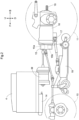
- the tractor includes left and right front wheels 10, left and right rear wheels 11, and a cover member 12.
- the tractor also includes body frames 2 and a driving section 3.
- the body frames 2 are supported by the left and right front wheels 10 and the left and right rear wheels 11.
- the cover member 12 is disposed in a front portion of the body of the tractor.
- the driving section 3 is behind the cover member 12. In other words, the cover member 12 is in front of the driving section 3.
- the driving section 3 includes a protective frame 30, a driver's seat 31, and a steering wheel 32.
- An operator can sit on the driver's seat 31. Accordingly, the operator can ride in the driving section 3.
- the operator steers the left and right front wheels 10 by operating the steering wheel 32.
- the operator can perform various driving operations in the driving section 3.
- the tractor includes a battery 4 for driving.
- the cover member 12 is configured to be pivotable about an opening/closing axis Q extending in the left-right direction of the body. Accordingly, the cover member 12 is configured to be openable and closable. When the cover member 12 is closed, the battery 4 for driving is covered by the cover member 12.
- the tractor includes an inverter 14 and a motor M.
- the battery 4 for driving supplies power to the inverter 14.
- the inverter 14 converts DC power supplied from the battery 4 for driving to AC power, and supplies the AC power to the motor M.
- the motor M is driven by the AC power supplied from the inverter 14.
- the tractor includes a hydraulic continuously variable transmission 15 and a transmission 16.
- the hydraulic continuously variable transmission 15 includes a hydraulic pump 15a and a hydraulic motor 15b.
- the hydraulic pump 15a is driven by rotational motive power transmitted from the motor M. As a result of the hydraulic pump 15a being driven, rotational motive power is output from the hydraulic motor 15b.
- the hydraulic continuously variable transmission 15 is configured to change the speed of rotational motive power between the hydraulic pump 15a and the hydraulic motor 15b. Also, the hydraulic continuously variable transmission 15 is configured to be capable of changing the transmission ratio in a stepless manner.
- the rotational motive power output from the hydraulic motor 15b is transmitted to the transmission 16.
- the speed of the rotational motive power transmitted to the transmission 16 is changed by a gear transmission mechanism included in the transmission 16, and the rotational motive power is distributed to the left and right front wheels 10 and the left and right rear wheels 11.
- the left and right front wheels 10 and the left and right rear wheels 11 are driven.
- the tractor also includes a middle PTO shaft 17 and a rear PTO shaft 18.
- Rotational motive power output from the motor M is distributed to the hydraulic pump 15a, the middle PTO shaft 17, and the rear PTO shaft 18.
- the middle PTO shaft 17 and the rear PTO shaft 18 are rotated by the distributed rotational motive power.
- a work device is connected to the middle PTO shaft 17 or the rear PTO shaft 18, the work device is driven by rotational motive power transmitted by the middle PTO shaft 17 or the rear PTO shaft 18.
- a grass cutting device 19 is connected to the middle PTO shaft 17 as shown in FIG. 2 .
- the grass cutting device 19 is driven by rotational motive power transmitted by the middle PTO shaft 17.
- the right and left body frames 2 and the transmission 16 are coupled to each other, and thus the body, serving as a framework of the tractor, is configured by the right and left portions of the body frame 2 and the transmission 16.
- the battery 4 for driving (hereinafter, referred to as “battery 4") is installed in a front portion of the body, and the battery 4 is housed in the closed cover member 12.
- a top face 12a of the cover member 12 is formed in a forward-descending shape in which it descends toward the front side when viewed in a side view, and side faces 12b of the cover member 12 extend along a front-rear direction when viewed in a plan view.
- a front grille 12c which is grid-shaped with high ventilation performance and serves as an introduction section, is provided in the front portion of the cover member 12, and side grilles 12d and 12e, which are grid-shaped with high ventilation performance, are provided at the right and left side faces 12b of the cover member 12. As the body moves forward, air is introduced into the cover member 12 mainly through the front grille 12c of the cover member 12.
- the battery 4 is provided with battery modules 6, a stack 7 (see FIGS. 11 and 12 ) in which a plurality of battery modules 6 (see FIGS. 11 and 12 ) are connected to each other, a housing case 1 (see FIGS. 7 and 8 ) in which a plurality of stacks 7 are housed, various devices (see FIG. 18 ) provided in an upper portion of the housing case 1, a housing cover 5 (see FIGS. 9 and 10 ) covering the top of the housing case 1 and the devices.
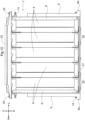
- the housing case 1 is provided with horizontal frames 33, 34, 37, 38, and 39, vertical frames 35 and 36, upper frames 40 and 44, first lower frames 41, second lower frames 42, third lower frames 43, side plates 45 and 46, a bottom plate 47, and the like to form a rectangular (quadrangle-shaped) box shape when viewed in a plan view.
- the right and left horizontal frames 33 located at the bottom of the housing case 1, and the front and rear horizontal frames 34 are coupled in a rectangular shape, and the front vertical frames 35 and rear vertical frames 36 are coupled to the ends of the horizontal frames 33 and 34.
- the front horizontal frame 37 is coupled to the vertical frames 35 while spanning the space therebetween, and the rear horizontal frame 38 is coupled to the vertical frames 36 while spanning the space therebetween.
- the right and left horizontal frames 39 are coupled to upper portions of the vertical frames 35 and 36 while spanning the spaces therebetween.
- Two first lower frames 41 are coupled to the horizontal frames 33 while spanning the space therebetween along a left-right direction.
- Three second lower frames 42 are disposed parallel to the first lower frames 41 when viewed in a plan view and are coupled to the horizontal frames 33 while spanning the space therebetween along the left-right direction.
- Large openings 42a are formed in the second lower frames 42.
- Two third lower frames 43 are disposed orthogonal to the first lower frames 41 and the second lower frames 42 when viewed in a plan view and are coupled to the horizontal frames 34 while spanning the space therebetween along the front-rear direction and are coupled to the first lower frames 41 and the second lower frames 42.
- an opening 43a as large as the openings 42a in the second lower frames 42 is formed in the third lower frame 43.
- Two upper frames 40 are coupled to the horizontal frames 39 while spanning the space therebetween along the left-right direction.
- Two upper frames 44 are coupled to the horizontal frames 37, 38, and 39 along the left-right direction. Large openings 44a are formed in the upper frames 44.
- the right and left side plates 45 in a flat plate shape are coupled to the horizontal frames 33 and 39 and the vertical frames 35 and 36.
- the front and rear side plates 46 in a flat plate shape are coupled to the horizontal frames 34, 37, and 38, and the vertical frames 35 and 36.
- the bottom plate 47 in a flat plate shape is coupled to the horizontal frames 33 and 34.
- five battery modules 6 are stacked and five battery modules 6 are coupled to each other while being lined up adjacent to each other, thereby forming one stack 7.
- Three stacks 7 are provided in the battery 4.
- a flat plate-shaped coupling member 8 and a coupling member 9 with a mounting portion 9a are provided, and the coupling member 8 and the coupling member 9 are coupled to each other.
- the coupling members 8 and 9 are attached to one side and another side of the stack 7 (battery modules 6), and four bolts 13 are passed through the coupling members 8 and 9 on one side, the battery modules 6, and the coupling members 8 and 9 on the other side to tighten them.
- the lower support members 21 and 22 are provided.
- the lower support member 21 is flat plate shaped, and four coupling parts 21a protruding outward are provided at each of one edge and another edge of the lower support member 21, while being lined up at a predetermined distance.
- the coupling parts 21a of the lower support member 21 are triangle-shaped and tapered with their width decreasing away from the lower support member 21.
- the lower support members 22 are flat plate shaped, and three coupling parts 22a protruding outward are provided at one edge of each lower support member 22, while being lined up at a predetermined distance.
- the coupling parts 22a of the lower support members 22 are triangle-shaped and tapered with their width decreasing away from the corresponding lower support member 22.
- the lower support member 21 is coupled to lower central portions of the battery modules 6 by bolts 20.
- the lower support members 22 are coupled to lower central portions of the battery modules 6 by the bolts 20.
- the upper support members 23 and 24 are provided.
- the upper support member 23 is formed by bending a plate material, and three coupling parts 23a protruding outward are provided at each of one edge and another edge of the upper support member 23, while being lined up at a predetermined distance.
- the coupling parts 23a of the upper support member 23 are triangle-shaped and tapered with their width decreasing away from the upper support member 23.
- the upper support members 24 are formed by bending a plate material, and three coupling parts 24a protruding outward are provided at one edge of each of the upper support members 24, while being lined up at a predetermined distance.
- the coupling parts 24a of the upper support members 24 are triangle-shaped and tapered with their width decreasing away from the corresponding upper support member 24.
- the upper support member 23 is coupled to upper portions of the battery modules 6 by bolts 25, so that the upper support member 23 is coupled to upper portions of the coupling members 8 by the bolts 25.
- the corresponding upper support member 24 is coupled to upper portions of the battery modules 6 by the bolts 25, so that the upper support member 24 is coupled to upper portions of the coupling members 8 by the bolts 25.
- the stacks 7 (battery modules 6) are combined with the coupling members 8 and 9, the lower support members 21 and 22, and the upper support members 23 and 24 into one piece to serve as one unit.
- the stack 7 to which the lower support member 21 and the upper support member 23 are coupled is installed in a central portion of the housing case 1.
- the stacks 7 to which the lower support members 22 and the upper support members 24 are coupled are respectively placed in a front portion and a rear portion of the housing case 1.
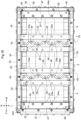
- the coupling parts 21a of the lower support member 21 are placed on the first lower frame 41 and are coupled to the first lower frame 41 by bolts 26.
- the central portion of the lower support member 21 is placed on the second lower frame 42, and the bolts 20 are positioned in the openings 42a and 43a in the second lower frame 42 and the third lower frame 43.
- the coupling parts 22a of the lower support member 22 are placed on the first lower frames 41 and are coupled to the first lower frames 41 by bolts 27. Another edge of each lower support member 22 is placed on the corresponding horizontal frame 34 and are coupled to the horizontal frame 34 by bolts 28.
- the central portions of the lower support members 22 are placed on the respective second lower frames 42 and the bolts 20 are positioned in the openings 42a and 43a in the second lower frame 42 and the third lower frame 43.
- the mounting portions 9a of the coupling members 9 are coupled to the horizontal frames 33 by bolts 50.
- the stacks 7 in which a plurality of battery modules 6 are coupled to each other are lined up adjacent to each other and are housed in the housing case 1.
- the plurality of lower support members 21 and 22 coupled to the lower portions of the battery modules 6, and the first lower frames 41 disposed along the spaces between the adjacent lower support members 21 and 22 are provided in the housing case 1.
- the coupling parts 21a of one lower support member 21 enter the respective spaces between the coupling parts 22a of the other lower support member 22, and the coupling parts 22a of the other lower support member 22 enter the respective spaces between the coupling parts 21a of the one lower support member 21.
- the coupling parts 21a and 22a of the one lower support member 21 and the other lower support member 22 are coupled to the first lower frame 41.
- the coupling parts 21a of the lower support member 21 are supported by the first lower frame 41 and the third lower frame 43 from below, and connections (near the bolts 20) of the lower support member 21 to the battery modules 6 are supported by the second lower frame 42 and the third lower frame 43 from below.
- the central stack 7 (battery modules 6) is considered to more easily vibrate than the front and rear stacks 7 (battery module 6).
- the number (four) of coupling parts 21a of the lower support member 21 is set to be larger than the number (three) of coupling parts 22a of the lower support member 22, so that the central stack 7 (battery module 6) is firmly coupled to the first lower frames 41.
- the coupling parts 23a of the upper support member 23 are placed on the upper frames 40 and are coupled to the upper frames 40 by bolts 29.
- the coupling parts 24a of the upper support members 24 are placed on the upper frames 40 and are coupled to the upper frames 40 by bolts 48.
- the upper frame 44 is placed on another edge of each upper support member 24 from above, and the bolts 25 of the upper support members 24 are inserted into the respective openings 4a in the upper frame 44.
- the upper frames 44 are bolted to the horizontal frames 37 and 39, and the upper frames 44 and the upper support members 24 are coupled to each other by bolts 49.
- the plurality of upper support members 23 and 24 coupled to the upper portions of the battery modules 6 and the upper frames 40 disposed along the space between adjacent upper support members 23 and 24 are provided in the housing case 1.
- the coupling parts 23a of one upper support member 23 enter the respective spaces between the coupling parts 24a of the other upper support member 24, and the coupling parts 24a of the other upper support member 24 enter the respective spaces between the coupling parts 23a of the one upper support member 23.
- the coupling parts 23a and 24a of the one upper support member 23 and the other upper support member 24 are coupled to the upper frames 40.
- three stacks 7 are housed in the housing case 1 via the lower support members 21 and 22, the upper support members 23 and 24, and the coupling members 8 and 9, are coupled to the housing case 1, and are lined up in the front-rear direction (horizontal direction).
- a substrate member 51 in a rectangular shape (quadrangle shape) when viewed in a plan view is coupled to the upper support members 23 and 24 (see FIG. 16 ), and the top of the housing case 1 is covered by the substrate member 51.
- Connection parts 52, 53, 54, and 55 are provided on the front horizontal frame 37.
- the connection part 52 is for charging the battery modules 6 with power supplied from an external power source (not shown).
- the connection part 53 is for supplying power from the battery modules 6 to the inverter 14 (see FIG. 2 ).
- the connection part 54 is for supplying power from the battery modules 6 to a DC-DC converter (not shown), and power stepped down to 12 V by the DC-DC converter is supplied to another battery (not shown).
- the connection part 55 is for being supplied with power from the above-described other battery.
- Openings 51a are formed in the substrate member 51 (housing case 1) at positions above the terminals 6a of the battery modules 6 at the right and left ends of the stacks 7.
- a harness 56 is connected between the terminal 6a (minus) of the battery module 6 at the right end of the front stack 7 and the terminal 6a (plus) of the battery module 6 at the left end of the central stack 7.
- a flat plate-shaped connection member 57 is connected between the terminal 6a (minus) of the battery module 6 at the right end of the central stack of 7 and the terminal 6a (plus) of the battery module 6 at the left end of the rear stack 7.
- Relay switches 58, 59, 60, and 61 are provided on the substrate member 51.
- a flat plate-shaped connection member 69 is connected between the terminal 6a (plus) of the battery module 6 at the left end of the front stack 7 and the relay switches 58 and 60.
- a flat plate-shaped connection member 70 is connected between the terminal 6a (minus) of the battery module 6 at the right end of the rear stack 7 and the relay switches 59 and 61.
- Harnesses 64 are connected between the relay switches 58 and 59, and the connection part 52, and the relay switches 58 and 59 function when the battery modules 6 are charged with power supplied from the external power source.
- Harnesses 65 are connected between the relay switches 60 and 61, and the connection part 53, and the relay switches 60 and 61 function when power is supplied from the battery modules 6 to the inverter 14.
- a shut-off part 66 is provided in a mid-way portion of the connection member 57.
- an operator brings the shut-off part 66 into a shut-off state.
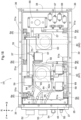
- pre-charge parts 67 and discharge parts 68 are provided in the left corner at the rear end of the substrate member 51.
- the pre-charge parts 67 and the discharge parts 68 are provided in an upper portion of the housing case 1, are provided at the upper rear end of the housing case 1, and are provided in the left corner at the upper rear end of the housing case 1.
- the pre-charge parts 67 When power supply is started from the battery modules 6 (battery 4) to the inverter 14 by a key-on operation, the pre-charge parts 67 perform processing for gradually supplying power to the inverter 14 for about several seconds.
- the discharge parts 68 When power supply from the battery modules 6 (battery 4) to the inverter 14 is shut off by a key-off operation, the discharge parts 68 perform processing for discharging power remaining in the inverter 14 (capacitor) for about several seconds.
- the three stacks 7 are lined up adjacent to each other at predetermined gaps A1 and A2.
- the gaps A1 and A2 extend over the entire width of the stack 7 and over the entire height of the stack 7 and are positioned below the respective upper frames 40.
- the front and central stacks 7 are provided so that the respective rear ends of the five battery modules 6 in the front stack 7 and the respective front ends of the five battery modules 6 in the central stack 7 face each other with a gap A1.
- the rear and central stacks 7 are provided so that the respective front ends of the five battery modules 6 in the rear stack 7 and the respective rear ends of the five battery modules 6 in the central stack 7 face each other with a gap A2.
- Two fan devices 62 and 63 are provided on the substrate member 51.
- the fan devices 62 and 63 are configured in a sirocco fan type, and circular ventilation holes 62a and 63a are provided in respective lower portions of the fan devices 62 and 63.
- the fan device 62 sucks air from the ventilation hole 62a of the fan device 62 and blows out the sucked air toward the front side.
- the fan device 63 sucks air from the ventilation hole 63a of the fan device 63 and blows out the sucked air toward the rear side.
- the ventilation holes 62a and 63a of the fan devices 62 and 63 are respectively provided at positions facing the upper portions of the gaps A1 and A2 when viewed in a side view, and are respectively provided in the centers of the gaps A1 and A2 in the left-right direction when viewed in the plan view.
- the ventilation holes 62a and 63a of the fan devices 62 and 63 have diameters set to be larger than the front-rear width of the upper frame 40.
- the ventilation holes 62a and 63a of the fan devices 62 and 63 protrude forward of the front end of the upper frame 40 and protrude rearward of the rear end of the upper frame 40, when viewed in a plan view.
- the housing cover 5 is provided on the top of the housing case 1, and the housing cover 5 covers the top of the housing case 1, the substrate member 51, the relay switches 58 to 61, the fan devices 62 and 63, the shut-off part 66, the pre-charge parts 67, the discharge parts 68, and the like, which are shown in FIG. 18 .
- the housing cover 5 is formed by bending a plate material and includes a top face 5a, a front face 5b, a rear face 5c, right and left side faces 5d, and right and left inclined faces 5e.
- the front face 5b, the rear face 5c, and the side faces 5d of the housing cover 5 extend in the vertical direction.
- the top face 5a of the housing cover 5 is formed in a forward-descending shape in which it descends toward the front side when viewed in a side view.
- the inclined faces 5e of the housing cover 5 are connected between the top face 5a and the side faces 5d of the housing cover 5, and are formed in a forward-descending shape in which they descend toward the front side when viewed in a side view and in a laterally-descending shape in which they descend toward the laterally outer side when viewed in a front view.
- the side portions of the front face 5b of the housing cover 5 are not adjacent to the front portions of the side faces 5d of the housing cover 5 and the front portions of the inclined faces 5e of the housing cover 5, and right and left openings 5f in a shape of an elongated gap are formed in the housing case 1. Since the fan device 62 shown in FIGS. 17 and 18 blows out sucked air toward the front side, the openings 5f through which air can be passed are provided at the positions of the housing cover 5 facing the blowing direction of the fan device 62.
- the side portions of the rear face 5c of the housing cover 5 are not adjacent to the rear portions of the side faces 5d of the housing cover 5 and the rear portions of the inclined faces 5e of the housing cover 5, and right and left openings 5g in a shape of an elongated gap are formed in the housing case 1. Since the fan device 63 shown in FIGS. 17 and 18 blows out sucked air toward the rear side, the openings 5g through which air can be passed are provided at the positions of the housing cover 5 facing the blowing direction of the fan device 63.
- the fan devices 62 and 63 are activated with power supplied to the connection part 55 by a key-on operation and are deactivated by a key-off operation.
- blowing direction (forward) of the fan device 62 and the blowing direction (backward) of the fan device 63 are set as opposite directions so that the blown air flows away from each other.
- the fan device 62 corresponds to the fan device 62 for the gap A1 between the central stack 7 and one stack 7
- the fan device 63 corresponds to the fan device 63 for the gap A2 between the central stack 7 and the other stack 7.
- the air inside the housing cover 5 (outside the housing case 1) is introduced into the housing case 1.
- the air inside the housing cover 5 (outside the housing case 1) is introduced into the housing case 1 mainly through the openings 51a in the substrate member 51 while passing by the terminals 6a of the battery modules 6.
- the top face 12a of the cover member 12 is formed in a forward-descending shape in which it descends toward the front side when viewed in a side view
- the top face 5a and the inclined faces 5e of the housing cover 5 are formed in a forward-descending shape in which they descend toward the front side when viewed in a side view.
- the top face 5a and the inclined faces 5e of the housing cover 5 and the top face 12a of the cover member 12 are arranged at a predetermined distance in the up-down direction, and a space B1 is formed between the top face 5a and the inclined faces 5e of the housing cover 5 and the top face 12a of the cover member 12, when viewed in a side view.
- the battery 4 (side plates 45) and the side faces 12b of the cover member 12 are arranged at a predetermined distance in the left-right direction, and right and left spaces B2 are formed between the battery 4 (side plates 45) and the side faces 12b of the cover member 12, when viewed in a plan view.
- the lower support members 21 and 22 may be removed from the stacks 7 (battery modules 6) in advance and coupled to the housing case 1.
- the upper support members 23 and 24 may be removed from the stacks 7 (battery modules 6).
- the coupling parts 21a and 22a of the lower support members 21 and 22 may be elongated rectangular when viewed in a plan view.
- the number of coupling parts 21a and 22a of the lower support members 21 and 22 may be respectively set to two and three, or four and five.
- the number of coupling parts 22a of the lower support member 22 may be larger than the number of coupling parts 21a at one edge of the lower support member 21.
- the coupling parts 23a and 24a of the upper support members 23 and 24 may be elongated rectangular when viewed in a plan view.
- the number of coupling parts 23a and 24a of the upper support members 23 and 24 may be respectively set to three and two, or five and four.
- the number of coupling parts 23a at one edge of the upper support member 23 may be larger than the number of coupling parts 24a of the upper support member 24.
- the pre-charge parts 67 and the discharge parts 68 shown in FIG. 18 may be provided, on the upper part (substrate member 51) of the housing case 1, in a central portion, in the left-right direction, at the rear end, in the right corner at the rear end, or in a central portion, in the left-right direction, at the front end, or may be provided in the right or left corner at the front end, in a central portion, in the front-rear direction, at the right side end, in the front or rear corner at the right side end, in a central portion, in the front-rear direction, at the left side end, or in the front or rear corner at the left side end.
- pre-charge parts 67 and the discharge parts 68 may be provided apart from each other on the upper part (substrate member 51) of the housing case 1.
- the pre-charge parts 67 and the discharge parts 68 may be provided in a lower portion of a front part of the housing case 1 or in a central portion of the front part in the up-down direction, or in a lower portion of a rear part of the housing case 1 or in a central portion of the rear part in the up-down direction, or may be provided in a lower portion of a right side part of the housing case 1 or in a central portion of the right side part in the up-down direction, or in a lower portion of a left side part of the housing case 1 or in a central portion of the left side part in the up-down direction.
- blowing directions of the fan devices 62 and 63 shown in FIG. 18 may be set to rightward and leftward, and the openings 5f and 5g of the housing cover 5 shown in FIGS. 9 and 10 may be formed in the right and left side faces 5d.
- the fan devices 62 and 63 and the openings 5f and 5g of the housing cover 5 are provided close to each other, and thus air blown out from the fan devices 62 and 63 easily flows out from the housing cover 5 through the openings 5f and 5g of the housing cover 5.
- the fan devices 62 and 63 shown in FIGS. 17 and 18 may be configured to suck air inside the housing cover 5 and blow out the air toward the gaps A1 and A2 (interior of the housing case 1) from the ventilation holes 62a and 63a of the fan devices 62 and 63.
- the air inside the housing case 1 flows out into the housing cover 5 while passing mainly by the terminals 6a of the battery modules 6 and passing through the openings 51a in the substrate member 51.
- the fan devices 62 and 63 shown in FIGS. 17 and 18 may also be provided on the side plate 45 or the bottom plate 47 of the housing case 1 while facing the side portions or the lower portions of the respective gaps A1 and A2.
- one or two stacks 7 may be provided, or four or more stacks 7 may also be provided. Less than five or at least six battery modules 6 may be coupled to each other to form a single stack 7. A plurality of stacks 7 may be lined up in the left-right direction.
- the number of fan devices 62 and 63 is set to one or three or more according to the numbers of stacks 7 and gaps A1 and A2.
- the front wheels 10 and the rear wheels 11 serve as the travel device of the present invention.
- right and left crawler travel devices may be provided as the travel device on the body.
- the present invention is applicable to not only a tractor but also another electric work vehicle such as an electric cart and a truck, is applicable to an electric work vehicle in which the battery 4 is installed in a rear portion of the body, and is applicable to an autonomous travel or radio control electric work vehicle with no operator on board.
Landscapes
- Engineering & Computer Science (AREA)
- Power Engineering (AREA)
- Mechanical Engineering (AREA)
- Transportation (AREA)
- Sustainable Energy (AREA)
- Life Sciences & Earth Sciences (AREA)
- Sustainable Development (AREA)
- Chemical & Material Sciences (AREA)
- Chemical Kinetics & Catalysis (AREA)
- Electrochemistry (AREA)
- General Chemical & Material Sciences (AREA)
- Manufacturing & Machinery (AREA)
- Aviation & Aerospace Engineering (AREA)
- Combustion & Propulsion (AREA)
- Battery Mounting, Suspending (AREA)
Abstract
Description
- The present invention relates to an electric work vehicle configured such that a travel device is driven by a motor. The present invention also relates to, in an electric work vehicle that includes a battery, a motor driven by power supplied from the battery, and a travel device driven by the motor, a configuration for cooling the battery. The present invention also relates to, in an electric work vehicle that includes a battery, a motor driven by power supplied from the battery, and a travel device driven by the motor, a configuration of the battery.
- As disclosed in
Patent Document 1, some electric work vehicles include a battery and an inverter supplied with power from the battery and have a configuration in which a motor is driven by power supplied from the inverter. - As disclosed in
Patent Document 2, some electric work vehicles of an air-cooling type include a cooling fan provided outside of a battery installed in a body, so that an air flow is generated outside of the battery by the cooling fan to cool the battery. - As disclosed in
Patent Document 2, some electric work vehicles have a configuration in which the entirety of a battery is constituted by stacks with a plurality of battery modules coupled to each other, and the stacks are lined up adjacent to each other and are housed in a housing case. -
- Patent Document 1:
JP 2021-955A - Patent Document 2:
JP 2021-953A - A problem for "
Background Art 1" is as follows. - Such an electric work vehicle as described above may be provided with a pre-charge part and a discharge part. The pre-charge part performs processing for gradually supplying power to the inverter at a start of power supply from the battery to the inverter. In response to power supply from the battery to the inverter being shut off, the discharge part performs processing for discharging power remaining in the inverter.
- The present invention aims to realize a configuration of an electric work vehicle in which a pre-charge part and a discharge part are provided in a compact manner.
- A problem for "
Background Art 2" is as follows. - In contrast to an electric work vehicle of an air-cooling type in which the outer side of the battery is cooled by air as described above, an electric work vehicle of an air-cooling type in which the inner side of the battery is cooled by air has been proposed.
- The present invention aims to realize a configuration of an electric work vehicle in which the inner side of a battery is efficiently cooled by air.
- A problem for "
Background Art 3" is as follows. - When an electric work vehicle travels on an uneven surface of the ground, vibration during the travel may be transmitted from the housing case to the stacks and the stacks (battery modules) may vibrate against the housing case. Accordingly, there is room for improvement in suppressing the vibration of the stacks (battery modules) against the housing case.
- The present invention aims to realize a configuration of an electric work vehicle in which the vibration of stacks (battery modules) against a housing case is suppressed.
- Solutions for "
Problem 1" are as follows. - The present invention is directed to an electric work vehicle comprising: a battery; an inverter configured to be supplied with power from the battery; a motor configured to be driven by power from the inverter; and a travel device configured to be driven by the motor,
- wherein the battery includes:
- a housing case in which a plurality of battery modules are housed;
- a pre-charge part configured to perform processing for gradually supplying power to the inverter at a start of power supply from the battery to the inverter; and
- a discharge part configured to perform processing for discharging power remaining in the inverter in response to power supply from the battery to the inverter being shut off, and
- the pre-charge part and the discharge part are provided in the housing case.
- According to the present invention, when the battery includes the housing case in which the plurality of battery modules are housed, since the pre-charge part and the discharge part are provided in the housing case, the battery realizes a compact layout of the housing case in which the plurality of battery modules are housed, the pre-charge part, and the discharge part. This is advantageous in terms of simplification of the structure.
- According to the present invention, there is no need of providing the pre-charge part and the discharge part at positions separate from the battery, which is also advantageous in terms of saving a space near the battery in the electric work vehicle.
- In the present invention, preferably, the pre-charge part and the discharge part are provided in an upper portion of the housing case.
- According to the present invention, since the pre-charge part and the discharge part are provided in an upper portion of the housing case, heat generated in the pre-charge part and the discharge part easily escapes upward, which is advantageous in terms of the heat dissipation of the battery.
- In the present invention, preferably, the pre-charge part and the discharge part are provided at a rear end of the housing case.
- According to the present invention, since the pre-charge part and the discharge part are provided at the upper rear end of the housing case, and heat generated in the pre-charge part and the discharge part easily escapes upward and rearward, which is advantageous in terms of the heat dissipation of the battery.
- In the present invention, preferably, the housing case is quadrangle-shaped when viewed in a plan view, and
the pre-charge part and the discharge part are provided in a right or left corner at the rear end of the housing case. - According to the present invention, since the pre-charge part and the discharge part are provided in a right or left corner at the upper rear end of the housing case, and heat generated in the pre-charge part and the discharge part easily escapes upward, rearward, and sideward, which is advantageous in terms of the heat dissipation of the battery.
- In the present invention, preferably, the housing case includes, on a top thereof, a housing cover covering the pre-charge part and the discharge part.
- According to the present invention, since the housing cover covering the pre-charge part and the discharge part is provided in an upper portion of the housing case, the pre-charge part and the discharge part are protected, which is advantageous in terms of preventing damage to the pre-charge part and the discharge part.
- Solutions for "
Problem 2" are as follows. - The present invention is directed to an electric work vehicle comprising: a battery; a motor configured to be driven by power from the battery; and a travel device configured to be driven by the motor,
wherein the battery includes: - a stack in which a plurality of battery modules are coupled to each other;
- a housing case in which a plurality of the stacks are housed, the stacks being lined up adjacent to each other at a predetermined gap; and
- a fan device that has a ventilation hole formed on an outer side of the housing case at a position facing the gap, the fan device being configured to be able to suck air in the housing case or supply air to the housing case via the ventilation hole.
- According to the present invention, the stack in which a plurality of battery modules are coupled to each other is included in the battery, and a plurality of the stacks are housed in the housing case.
- In this case, the plurality of stacks are housed in the housing case while being lined up adjacent to each other at a predetermined gap, and thus air easily flows through the gap between adjacent stacks.
- According to the present invention, the fan device is provided, and the ventilation hole of the fan device is formed on the outer side of the housing case at a position facing the gap between adjacent stacks, so that the ventilation hole is close to the gap between the adjacent stacks.
- With this, when air is sucked (supplied) by the fan device, air in the gap between adjacent stacks is efficiently sucked (air is efficiently supplied to the gap between adjacent stacks) through the ventilation hole of the fan device, and flows in the gap between adjacent stacks, allowing the stacks to be efficiently cooled with the air and allowing the interior of the battery to be efficiently cooled with the air.
- In the present invention, preferably, the housing case includes an opening through which air is passable, the opening being provided at a position facing a terminal of the battery modules.
- According to the present invention, when air in the gap between adjacent stacks is sucked by the fan device, air outside the housing case is introduced into the housing case.
- Since the opening is provided at a position facing the terminal of the battery module of the housing case, air outside the housing case is passed through the opening of the housing case and is introduced into the housing case while passing by the terminal of the battery modules, allowing the terminal of the battery modules to be efficiently cooled. This is advantageous in terms of cooling the interior of the battery.
- According to the present invention, when air is supplied into the gap between adjacent stacks by the fan device, air in the housing case is pushed out to the outside of the housing case.
- Since the opening is provided at a position facing the terminal of the battery modules of the housing case, air in the housing case is passed by the terminal of the battery module and is pushed out to the outside of the housing case through the opening in the housing case, allowing the terminal of the battery modules to be efficiently cooled. This is advantageous in terms of cooling the interior of the battery.
- In the present invention, preferably, the plurality of battery modules are coupled to each other while being lined up adjacent to each other to constitute the stack, and
adjacent stacks are provided in a manner such that terminals of the plurality of battery modules in one stack and terminals of the plurality of battery modules in another stack face each other with the gap. - According to the present invention, when gaps are formed between adjacent stacks, the battery modules of the adjacent stacks face the gaps.
- With this, when air is sucked (supplied) by the fan device and flows through the gaps between the adjacent stacks, the battery modules of the adjacent stacks are efficiently cooled with less imbalance, which is advantageous in terms of cooling the interior of the battery.
- In the present invention, preferably, the plurality of stacks are lined up in a horizontal direction, and
the ventilation hole is provided at a position facing an upper portion of the gap. - According to the present invention, since the plurality of stacks are lined up in the horizontal direction and the gap between adjacent stacks extend along the up-down direction, hot air in the gap easily rises upward of the gap.
- According to the present invention, since the ventilation hole of the fan device is provided at a position facing an upper portion of the gap, the ventilation hole of the fan device is located close to hot air gathering in the upper portion of the gap between adjacent stacks, and air is directly sucked (supplied) by the fan device, which is advantageous in terms of cooling the interior of the battery.
- In the present invention, preferably, the electric work vehicle includes a housing cover covering the fan device and an upper portion of the housing case.
- According to the present invention, since the housing cover covering the fan device and the upper portion of the housing is provided, the fan device is protected, which is advantageous in terms of preventing damage to the fan device.
- In the present invention, preferably, the housing cover includes an opening through which air is passable at a position facing a blowing direction or a sucking direction of the fan device.
- According to the present invention, since the opening in the housing cover is provided while facing the blowing direction of the fan device, when air in the gap between adjacent stacks is sucked by the fan device, air blown from the fan device easily flows out from the housing cover through the opening in the housing cover, which is advantageous in terms of cooling the interior of the battery.
- According to the present invention, since the opening in the housing cover is provided while facing the sucking direction of the fan device, when air is supplied to the gap between adjacent stacks by the fan device, air outside the housing cover is easily introduced into the housing cover via the opening in the housing cover, which is advantageous in terms of cooling the interior of the battery.
- In the present invention, preferably, the fan device is configured to be able to suck air in the housing case, and
- in the one stack adjacent to one side of a central stack and another stack adjacent to another side of the central stack,
- a blowing direction of the fan device with respect to the gap between the central stack and the one stack, and a blowing direction of the fan device with respect to the gap between the central stack and the other stack are set as opposite directions so that blown air flows away from each other.
- A case is assumed in which, for example, three stacks are lined up with a gap, a fan device that corresponds to the gap between the central stack and one stack, and a fan device that corresponds to the gap between the central stack and the other stack are provided, and the fan devices are configured to be able to suck air in the housing case.
- According to the present invention, air blown from one fan device and air blown from the other fan device flow in opposite directions so that they move away from each other, and thus air blown from the one fan device and the other fan device hardly gather at one position, which is advantageous in terms of cooling the interior of the battery.
- In the present invention, preferably, the electric work vehicle further includes:
- a driving section in which an operator rides and performs driving; and
- a cover member that is provided in front of the driving section and includes, in a front portion of the cover member, an introduction section through which external air is introduced, the cover member including a top face formed in a forward-descending shape in which the top face descends toward a front side,
- wherein the battery is housed in the cover member, and
- a housing cover that covers the fan device and a top of the housing case is provided, and
- the housing cover includes a top face formed in a forward-descending shape in which the top face descends toward a front side, and the top face of the housing cover and the top face of the cover member are arranged at a predetermined distance in an up-down direction.
- In some electric work vehicles, a cover member is in front of the driving section in which an operator rides and performs driving, and the battery is housed in the cover member.
- In this case, an introduction section through which external air is introduced is provided in a front portion of the cover member, and as the electric work vehicle moves forward, air outside the cover member may be introduced into the cover member from the introduction section of the cover member and may be supplied to the outside of the battery.
- A configuration is also possible in which the top face of the cover member is formed in a forward-descending shape in which it descends toward the front side, and a field of front vision from the driving section is ensured.
- According to the present invention, since the housing cover covering upper portions of the fan device and the housing is provided, the fan device is protected, which is advantageous in terms of preventing damage to the fan device.
- According to the present invention, since the top face of the housing cover is formed in a forward-descending shape in which it descends toward a front side, and the top face of the housing cover and the top face of the cover member are arranged at a predetermined distance in the up-down direction, the cross-sectional area of a space between the top face of the housing cover and the top face of the cover member hardly varies from the front end of the housing cover to the rear end of the housing cover.
- According to the present invention, when, as the electric work vehicle moves forward, air outside the cover member is introduced into the cover member from the introduction section of the cover member and enters the space between the top face of the housing cover and the top face of the cover member, the air easily flow to the rear side without accumulating in the space between the top face of the housing cover and the top face of the cover member.
- This promotes exchange of air inside the cover member (in the surroundings of the battery) and suppresses an increase in temperature of the interior of the cover member (in the surroundings of the battery), which is advantageous in terms of cooling the interior of the battery.
- Solutions for "
Problem 3" are as follows. - The present invention is directed to an electric work vehicle comprising: a battery; a motor configured to be driven by power from the battery; and a travel device configured to be driven by the motor,
- wherein the battery includes: a stack in which a plurality of battery modules are coupled to each other; and a housing case in which a plurality of the stacks lined up adjacent to each other are housed,
- the housing case includes: a plurality of lower support members coupled to lower portions of the battery modules; and a first lower frame disposed along a space between adjacent lower support members,
- each of the lower support members includes a plurality of coupling parts protruding outward, the plurality of coupling parts being lined up at a predetermined distance, and
- adjacent lower support members are arranged in a manner such that the coupling parts of one lower support member enter respective spaces between the coupling parts of the other lower support member, and the coupling parts of the other lower support member enter respective spaces between the coupling parts of the one lower support member, and the coupling parts of the one lower support member and the other lower support member are coupled to the first lower frame.
- According to the present invention, the plurality of lower support members are provided in the housing case of the battery, lower portions of the battery modules are coupled to the lower support members, and lower portions of the stacks are supported by the lower support members. Each of the lower support members includes a plurality of coupling parts that protrude outward and are lined up at a predetermined distance, and the first lower frame disposed along a space between adjacent lower support members.
- According to the present invention, adjacent lower support members are arranged in a manner such that the coupling parts of one lower support member enter the respective spaces between the coupling parts of the other lower support member, and the coupling parts of the other lower support member enter the respective spaces between the coupling parts of the one lower support member. The coupling parts of the one lower support member and the other lower support member are coupled to the first lower frame.
- Due to a configuration in which the coupling parts of the one lower support member and the coupling parts of the other lower support member respectively entering the spaces formed by the coupling parts of the counterpart lower support member, the coupling parts of the one lower support member and the other lower support member are reasonably coupled to the first lower frame even when multiple coupling parts are included in the one and the other lower support members.
- As a result of the multiple coupling parts of the lower support members being coupled to the first lower frame, the stacks (battery modules) are firmly coupled to the first lower frame via the lower support members, thereby suppressing the vibration of the stacks (battery modules) against the housing case, which is advantageous in terms of preventing damage to the stacks (battery modules).
- In the present invention, preferably, the coupling parts of the lower support members are tapered with a width thereof decreasing away from the corresponding lower support member when viewed in a plan view.
- According to the present invention, due to the tapered coupling parts of the lower support members when viewed in a plan view, it is possible to set the distance between a coupling part of one lower support member and a coupling part of another lower support member in a longitudinal direction of the first lower frame to a small distance, compared to a case where the coupling parts of the lower support members are quadrangle-shaped when viewed in a plan view, making it possible to provide a large number of coupling parts in the lower support member.
- In contrast to the thin ends of the coupling parts of the lower support members, the base parts of the coupling parts of the lower support members have a large width, and thus the coupling parts of the lower support members have sufficient strength.
- As a result, the one lower support member and the other lower support member can have a large number of coupling parts having sufficient strength and the stacks (battery modules) are firmly coupled to the first lower frame via the lower support members, which is advantageous in terms of suppressing the vibration of the stacks (battery modules) against the housing case and preventing damage to the stacks (battery modules).
- In the present invention, preferably, the housing case includes a second lower frame disposed parallel to the first lower frame when viewed in a plan view, and
the second lower frame supports connections of the lower support member to the battery modules from below. - According to the present invention, in the housing case of the battery, the second lower frame is disposed parallel to the first lower frame and the connections of the lower support members to the battery modules are supported by the second lower frame from below. That is, the portions of the lower support members apart from the coupling parts are supported by the second lower frame, and thus the weight of the stacks (battery modules) is supported by the first lower frame and the second lower frame via the lower support members.
- This is advantageous in terms of suppressing the vibration of the stacks (battery modules) against the housing case and preventing damage to the stacks (battery modules), since the coupling parts of the lower support members are coupled to the first lower frame, the portions of the lower support members away from the coupling parts are supported by the second lower frame, and the weights of the stacks (battery modules) are supported by the first lower frame and the second lower frame.
- In the present invention, preferably, the housing case includes a third lower frame disposed orthogonal to the first lower frame and the second lower frame when viewed in a plan view, and
the third lower frame is coupled to the first lower frame and the second lower frame. - According to the present invention, in the housing case of the battery, the third lower frame is disposed orthogonal to the first lower frame and the second lower frame when viewed in a plan view, and the third lower frame is coupled to the first lower frame and the second lower frame.
- This is advantageous in terms of suppressing the vibration of the stacks (battery modules) against the housing case and preventing damage to the stacks (battery modules), since the first lower frame and the second lower frame have improved rigidity relative to that of the third lower frame, and the weights of the stacks (battery modules) are supported by the first lower frame, the second lower frame, and the third lower frame.
- In the present invention, preferably, the housing case includes: a plurality of upper support members coupled to upper portions of the battery modules; and an upper frame disposed along a space between adjacent upper support members,
- each of the upper support members includes a plurality of coupling parts protruding outward, the plurality of coupling parts being lined up at a predetermined distance,
- adjacent upper support members are arranged in a manner such that the coupling parts of one upper support member enter respective spaces between the coupling parts of the other upper support member, and the coupling parts of the other upper support member enter respective spaces between the coupling parts of the one upper support member, and the coupling parts of the one upper support member and the other upper support member are coupled to the upper frame.
- According to the present invention, in the housing case of the battery, the plurality of upper support members are provided, upper portions of the battery modules are coupled to the upper support members, and upper portions of the stacks are supported by the upper support members.
- Each of the upper support members has a plurality of coupling parts that protrude outward and are lined up at a predetermined distance, and the upper frame is disposed along a space between adjacent upper support members.
- Adjacent upper support members are arranged in a manner such that the coupling parts of one upper support member enter the respective spaces between the coupling parts of the other upper support member, and the coupling parts of the other upper support member enter the respective spaces between the coupling parts of the one upper support member. The coupling parts of the one upper support member and the other upper support member are coupled to the upper frame.
- Due to a configuration in which the coupling parts of the one upper support member and the other upper support member respectively entering the spaces formed by the coupling parts of the counterpart upper support member, the coupling parts of the one upper support member and the other upper support member are reasonably coupled to the upper frame even when multiple coupling parts are included in the one upper support member and the other upper support member. As a result of the multiple coupling parts of the upper support members are coupled to the upper frame, the stacks (battery modules) are firmly coupled to the upper frame via the upper support members.
- According to the present invention, in addition to the lower portions of the stacks (battery modules) being supported by the first lower frame via the lower support members, the upper portions of the stacks (battery modules) are supported by the upper frame via the upper support members, and due to multiple coupling parts of the upper support members being coupled to the upper frame, the stacks (battery modules) are firmly coupled to the upper frame via the upper support members, which is advantageous in terms of suppressing the vibration of the stacks (battery modules) against the upper frame via the upper support members and preventing damage to the stacks (battery modules).
- In the present invention, preferably, the coupling parts of the upper support members are tapered with a width thereof decreasing away from the corresponding upper support member when viewed in a plan view.
- According to the present invention, due to the tapered coupling parts of the upper support members when viewed in a plan view, it is possible to set the distance between the coupling part of one upper support member and the coupling part of the other upper support member in a longitudinal direction of the upper frame to a small distance, compared to a case where the coupling parts of the upper support members are quadrangle-shaped when viewed in a plan view, making it possible to provide a large number of coupling parts in the upper support member.
- In contrast to the thin ends of the coupling parts of the upper support members, the base parts of the coupling parts of the upper support members have a large width, and thus the coupling parts of the upper support members have sufficient strength.
- As a result, the one upper support member and the other upper support member can have a large number of coupling parts having sufficient strength and the stacks (battery modules) are firmly coupled to the upper frame via the upper support members, which is advantageous in terms of suppressing the vibration of the stacks (battery modules) against the housing case and preventing damage to the stacks (battery modules).
-
-
FIG. 1 is a left side view of a tractor. -
FIG. 2 is a left side view showing a layout of an inverter and the like. -
FIG. 3 is a diagram showing a flow of motive power transmission. -
FIG. 4 is a left side view of the vicinity of a cover member. -
FIG. 5 is a longitudinal left side view of the vicinity of the cover member. -
FIG. 6 is a horizontal plan view of the vicinity of the cover member. -
FIG. 7 is a left side view of a housing case. -
FIG. 8 is a plan view of the housing case. -
FIG. 9 is a left side view of a battery. -
FIG. 10 is a plan view of the battery. -
FIG. 11 is a left side view of stacks, a lower support member, and an upper support member. -
FIG. 12 is a front view of the stacks, the lower support member, and the upper support member. -
FIG. 13 is a bottom view of the stacks, the lower support member, and the upper support member. -
FIG. 14 is a longitudinal plan view of the vicinity of the lower support member in the housing case. -
FIG. 15 is a plan view of the stacks, the lower support member, and the upper support member. -
FIG. 16 is a plan view of the vicinity of the upper support member in the housing case. -
FIG. 17 is a left side view of the housing case and the stacks, as well as the vicinity of a fan device. -
FIG. 18 is a plan view of the vicinity of a substrate member and the fan device in the housing case. - An embodiment of the present invention will be described based on the drawings. In the following description, unless otherwise stated, the direction of an arrow F and the direction of an arrow B in the drawings will be respectively referred to as "the front side" and "the rear side", and the direction of an arrow L and the direction of an arrow R in the drawings will be respectively referred to as "the left side" and "the right side". Also, the direction of an arrow U and the direction of an arrow D in the drawings will be respectively referred to as "the upper side" and "the lower side".
- The following describes a tractor according to the present embodiment. As shown in
FIG. 1 , the tractor includes left and rightfront wheels 10, left and rightrear wheels 11, and acover member 12. - The tractor also includes body frames 2 and a
driving section 3. The body frames 2 are supported by the left and rightfront wheels 10 and the left and rightrear wheels 11. - The
cover member 12 is disposed in a front portion of the body of the tractor. Thedriving section 3 is behind thecover member 12. In other words, thecover member 12 is in front of thedriving section 3. - The
driving section 3 includes aprotective frame 30, a driver'sseat 31, and asteering wheel 32. An operator can sit on the driver'sseat 31. Accordingly, the operator can ride in thedriving section 3. The operator steers the left and rightfront wheels 10 by operating thesteering wheel 32. The operator can perform various driving operations in thedriving section 3. - The tractor includes a
battery 4 for driving. Thecover member 12 is configured to be pivotable about an opening/closing axis Q extending in the left-right direction of the body. Accordingly, thecover member 12 is configured to be openable and closable. When thecover member 12 is closed, thebattery 4 for driving is covered by thecover member 12. - As shown in
FIG. 2 , the tractor includes aninverter 14 and a motor M. Thebattery 4 for driving supplies power to theinverter 14. Theinverter 14 converts DC power supplied from thebattery 4 for driving to AC power, and supplies the AC power to the motor M. The motor M is driven by the AC power supplied from theinverter 14. - As shown in
FIGS. 2 and3 , the tractor includes a hydraulic continuouslyvariable transmission 15 and atransmission 16. As shown inFIG. 3 , the hydraulic continuouslyvariable transmission 15 includes ahydraulic pump 15a and ahydraulic motor 15b. - The
hydraulic pump 15a is driven by rotational motive power transmitted from the motor M. As a result of thehydraulic pump 15a being driven, rotational motive power is output from thehydraulic motor 15b. The hydraulic continuouslyvariable transmission 15 is configured to change the speed of rotational motive power between thehydraulic pump 15a and thehydraulic motor 15b. Also, the hydraulic continuouslyvariable transmission 15 is configured to be capable of changing the transmission ratio in a stepless manner. - The rotational motive power output from the
hydraulic motor 15b is transmitted to thetransmission 16. The speed of the rotational motive power transmitted to thetransmission 16 is changed by a gear transmission mechanism included in thetransmission 16, and the rotational motive power is distributed to the left and rightfront wheels 10 and the left and rightrear wheels 11. Thus, the left and rightfront wheels 10 and the left and rightrear wheels 11 are driven. - As shown in
FIGS. 2 and3 , the tractor also includes amiddle PTO shaft 17 and arear PTO shaft 18. Rotational motive power output from the motor M is distributed to thehydraulic pump 15a, themiddle PTO shaft 17, and therear PTO shaft 18. Themiddle PTO shaft 17 and therear PTO shaft 18 are rotated by the distributed rotational motive power. - If a work device is connected to the
middle PTO shaft 17 or therear PTO shaft 18, the work device is driven by rotational motive power transmitted by themiddle PTO shaft 17 or therear PTO shaft 18. For example, in the present embodiment, agrass cutting device 19 is connected to themiddle PTO shaft 17 as shown inFIG. 2 . Thegrass cutting device 19 is driven by rotational motive power transmitted by themiddle PTO shaft 17. - As shown in
FIG. 1 , the right and left body frames 2 and thetransmission 16 are coupled to each other, and thus the body, serving as a framework of the tractor, is configured by the right and left portions of thebody frame 2 and thetransmission 16. - As shown in
FIGS. 4 ,5, and 6 , thebattery 4 for driving (hereinafter, referred to as "battery 4") is installed in a front portion of the body, and thebattery 4 is housed in theclosed cover member 12. Atop face 12a of thecover member 12 is formed in a forward-descending shape in which it descends toward the front side when viewed in a side view, and side faces 12b of thecover member 12 extend along a front-rear direction when viewed in a plan view. - A
front grille 12c, which is grid-shaped with high ventilation performance and serves as an introduction section, is provided in the front portion of thecover member 12, andside grilles cover member 12. As the body moves forward, air is introduced into thecover member 12 mainly through thefront grille 12c of thecover member 12. - The
battery 4 is provided withbattery modules 6, a stack 7 (seeFIGS. 11 and12 ) in which a plurality of battery modules 6 (seeFIGS. 11 and12 ) are connected to each other, a housing case 1 (seeFIGS. 7 and8 ) in which a plurality ofstacks 7 are housed, various devices (seeFIG. 18 ) provided in an upper portion of thehousing case 1, a housing cover 5 (seeFIGS. 9 and 10 ) covering the top of thehousing case 1 and the devices. - As shown in
FIGS. 7 to 10 , thehousing case 1 is provided withhorizontal frames vertical frames upper frames lower frames 41, secondlower frames 42, thirdlower frames 43,side plates bottom plate 47, and the like to form a rectangular (quadrangle-shaped) box shape when viewed in a plan view. - As shown in
FIGS. 7 and8 , the right and lefthorizontal frames 33 located at the bottom of thehousing case 1, and the front and rearhorizontal frames 34 are coupled in a rectangular shape, and the frontvertical frames 35 and rearvertical frames 36 are coupled to the ends of thehorizontal frames horizontal frame 37 is coupled to thevertical frames 35 while spanning the space therebetween, and the rearhorizontal frame 38 is coupled to thevertical frames 36 while spanning the space therebetween. The right and lefthorizontal frames 39 are coupled to upper portions of thevertical frames - Two first
lower frames 41 are coupled to thehorizontal frames 33 while spanning the space therebetween along a left-right direction. Three secondlower frames 42 are disposed parallel to the firstlower frames 41 when viewed in a plan view and are coupled to thehorizontal frames 33 while spanning the space therebetween along the left-right direction.Large openings 42a are formed in the second lower frames 42. - Two third
lower frames 43 are disposed orthogonal to the firstlower frames 41 and the secondlower frames 42 when viewed in a plan view and are coupled to thehorizontal frames 34 while spanning the space therebetween along the front-rear direction and are coupled to the firstlower frames 41 and the second lower frames 42. At each position at which a secondlower frame 42 and a thirdlower frame 43 are coupled to each other, anopening 43a as large as theopenings 42a in the secondlower frames 42 is formed in the thirdlower frame 43. - Two
upper frames 40 are coupled to thehorizontal frames 39 while spanning the space therebetween along the left-right direction. Twoupper frames 44 are coupled to thehorizontal frames Large openings 44a are formed in the upper frames 44. - As shown in
FIGS. 9 and 10 , the right and leftside plates 45 in a flat plate shape are coupled to thehorizontal frames vertical frames rear side plates 46 in a flat plate shape are coupled to thehorizontal frames vertical frames bottom plate 47 in a flat plate shape is coupled to thehorizontal frames - As shown in
FIGS. 11 and12 , fivebattery modules 6 are stacked and fivebattery modules 6 are coupled to each other while being lined up adjacent to each other, thereby forming onestack 7. Threestacks 7 are provided in thebattery 4. - A flat plate-shaped
coupling member 8 and acoupling member 9 with a mountingportion 9a are provided, and thecoupling member 8 and thecoupling member 9 are coupled to each other. Thecoupling members bolts 13 are passed through thecoupling members battery modules 6, and thecoupling members - With this, the five
battery modules 6 are coupled to each other while being compressed by thecoupling members bolts 13. - As shown in
FIGS. 11 to 14 , thelower support members - As shown in
FIGS. 11 ,12 , and13 , thelower support member 21 is flat plate shaped, and fourcoupling parts 21a protruding outward are provided at each of one edge and another edge of thelower support member 21, while being lined up at a predetermined distance. When viewed in a plan view, thecoupling parts 21a of thelower support member 21 are triangle-shaped and tapered with their width decreasing away from thelower support member 21. - As shown in
FIG. 14 , thelower support members 22 are flat plate shaped, and threecoupling parts 22a protruding outward are provided at one edge of eachlower support member 22, while being lined up at a predetermined distance. When viewed in a plan view, thecoupling parts 22a of thelower support members 22 are triangle-shaped and tapered with their width decreasing away from the correspondinglower support member 22. - As shown in
FIGS. 11 ,12 , and13 , in onestack 7 of the threestacks 7, thelower support member 21 is coupled to lower central portions of thebattery modules 6 bybolts 20. - As shown in
FIG. 14 , in twostacks 7 of the threestacks 7, thelower support members 22 are coupled to lower central portions of thebattery modules 6 by thebolts 20. - As shown in
FIGS. 11 ,12 ,15 , and16 , theupper support members - As shown in
FIGS. 11 ,12 , and15 , theupper support member 23 is formed by bending a plate material, and threecoupling parts 23a protruding outward are provided at each of one edge and another edge of theupper support member 23, while being lined up at a predetermined distance. When viewed in a plan view, thecoupling parts 23a of theupper support member 23 are triangle-shaped and tapered with their width decreasing away from theupper support member 23. - As shown in
FIG. 16 , theupper support members 24 are formed by bending a plate material, and threecoupling parts 24a protruding outward are provided at one edge of each of theupper support members 24, while being lined up at a predetermined distance. When viewed in a plan view, thecoupling parts 24a of theupper support members 24 are triangle-shaped and tapered with their width decreasing away from the correspondingupper support member 24. - As shown in
FIGS. 11 ,12 , and15 , in onestack 7 to which thelower support member 21 is coupled, among the threestacks 7, theupper support member 23 is coupled to upper portions of thebattery modules 6 bybolts 25, so that theupper support member 23 is coupled to upper portions of thecoupling members 8 by thebolts 25. - As shown in
FIG. 16 , in each of twostacks 7 to which thelower support member 22 is coupled, among the threestacks 7, the correspondingupper support member 24 is coupled to upper portions of thebattery modules 6 by thebolts 25, so that theupper support member 24 is coupled to upper portions of thecoupling members 8 by thebolts 25. - As described above, the stacks 7 (battery modules 6) are combined with the
coupling members lower support members upper support members - As shown in
FIG. 14 , in a state in which the upper frames 44 (seeFIG. 16 ) of thehousing case 1 are removed, thestack 7 to which thelower support member 21 and theupper support member 23 are coupled is installed in a central portion of thehousing case 1. Thestacks 7 to which thelower support members 22 and theupper support members 24 are coupled are respectively placed in a front portion and a rear portion of thehousing case 1. - In the
stack 7 to which thelower support member 21 and theupper support member 23 are coupled, thecoupling parts 21a of thelower support member 21 are placed on the firstlower frame 41 and are coupled to the firstlower frame 41 bybolts 26. The central portion of thelower support member 21 is placed on the secondlower frame 42, and thebolts 20 are positioned in theopenings lower frame 42 and the thirdlower frame 43. - In the
stacks 7 to which thelower support members 22 and theupper support members 24 are coupled, thecoupling parts 22a of thelower support member 22 are placed on the firstlower frames 41 and are coupled to the firstlower frames 41 bybolts 27. Another edge of eachlower support member 22 is placed on the correspondinghorizontal frame 34 and are coupled to thehorizontal frame 34 bybolts 28. The central portions of thelower support members 22 are placed on the respective secondlower frames 42 and thebolts 20 are positioned in theopenings lower frame 42 and the thirdlower frame 43. - In the
stack 7 to which thelower support member 21 and theupper support member 23 are coupled, and thestacks 7 to which thelower support member 22 and theupper support member 24 are coupled, as shown inFIG. 17 , the mountingportions 9a of thecoupling members 9 are coupled to thehorizontal frames 33 bybolts 50. - With the above-described configuration, in the
battery 4, thestacks 7 in which a plurality ofbattery modules 6 are coupled to each other are lined up adjacent to each other and are housed in thehousing case 1. The plurality oflower support members battery modules 6, and the firstlower frames 41 disposed along the spaces between the adjacentlower support members housing case 1. - In the adjacent
lower support members coupling parts 21a of onelower support member 21 enter the respective spaces between thecoupling parts 22a of the otherlower support member 22, and thecoupling parts 22a of the otherlower support member 22 enter the respective spaces between thecoupling parts 21a of the onelower support member 21. Thecoupling parts lower support member 21 and the otherlower support member 22 are coupled to the firstlower frame 41. - The
coupling parts 21a of thelower support member 21 are supported by the firstlower frame 41 and the thirdlower frame 43 from below, and connections (near the bolts 20) of thelower support member 21 to thebattery modules 6 are supported by the secondlower frame 42 and the thirdlower frame 43 from below. - The central stack 7 (battery modules 6) is considered to more easily vibrate than the front and rear stacks 7 (battery module 6). On each of the first
lower frames 41, the number (four) ofcoupling parts 21a of thelower support member 21 is set to be larger than the number (three) ofcoupling parts 22a of thelower support member 22, so that the central stack 7 (battery module 6) is firmly coupled to the first lower frames 41. - As described above, when the
stack 7 to which thelower support member 21 and theupper support member 23 are coupled is installed in a central portion of thehousing case 1, as shown inFIG. 16 , thecoupling parts 23a of theupper support member 23 are placed on theupper frames 40 and are coupled to theupper frames 40 bybolts 29. - As described above, when the
stacks 7 to which thelower support member 22 and theupper support member 24 are coupled are respectively installed in a front portion and a rear portion of thehousing case 1, thecoupling parts 24a of theupper support members 24 are placed on theupper frames 40 and are coupled to theupper frames 40 bybolts 48. - The
upper frame 44 is placed on another edge of eachupper support member 24 from above, and thebolts 25 of theupper support members 24 are inserted into the respective openings 4a in theupper frame 44. Theupper frames 44 are bolted to thehorizontal frames upper frames 44 and theupper support members 24 are coupled to each other bybolts 49. - With the above-described configuration, in the
battery 4, the plurality ofupper support members battery modules 6 and theupper frames 40 disposed along the space between adjacentupper support members housing case 1. - In the adjacent
upper support members coupling parts 23a of oneupper support member 23 enter the respective spaces between thecoupling parts 24a of the otherupper support member 24, and thecoupling parts 24a of the otherupper support member 24 enter the respective spaces between thecoupling parts 23a of the oneupper support member 23. Thecoupling parts upper support member 23 and the otherupper support member 24 are coupled to the upper frames 40. - As described above, three stacks 7 (battery modules 6) are housed in the
housing case 1 via thelower support members upper support members coupling members housing case 1, and are lined up in the front-rear direction (horizontal direction). - As shown in
FIG. 18 , asubstrate member 51 in a rectangular shape (quadrangle shape) when viewed in a plan view is coupled to theupper support members 23 and 24 (seeFIG. 16 ), and the top of thehousing case 1 is covered by thesubstrate member 51.Connection parts horizontal frame 37. - The
connection part 52 is for charging thebattery modules 6 with power supplied from an external power source (not shown). Theconnection part 53 is for supplying power from thebattery modules 6 to the inverter 14 (seeFIG. 2 ). Theconnection part 54 is for supplying power from thebattery modules 6 to a DC-DC converter (not shown), and power stepped down to 12 V by the DC-DC converter is supplied to another battery (not shown). Theconnection part 55 is for being supplied with power from the above-described other battery. - In three
stacks 7, fivebattery modules 6 are connected in series to each other.Openings 51a are formed in the substrate member 51 (housing case 1) at positions above theterminals 6a of thebattery modules 6 at the right and left ends of thestacks 7. - A
harness 56 is connected between the terminal 6a (minus) of thebattery module 6 at the right end of thefront stack 7 and theterminal 6a (plus) of thebattery module 6 at the left end of thecentral stack 7. A flat plate-shapedconnection member 57 is connected between the terminal 6a (minus) of thebattery module 6 at the right end of the central stack of 7 and theterminal 6a (plus) of thebattery module 6 at the left end of therear stack 7. - Relay switches 58, 59, 60, and 61 are provided on the
substrate member 51. A flat plate-shapedconnection member 69 is connected between the terminal 6a (plus) of thebattery module 6 at the left end of thefront stack 7 and the relay switches 58 and 60. A flat plate-shapedconnection member 70 is connected between the terminal 6a (minus) of thebattery module 6 at the right end of therear stack 7 and the relay switches 59 and 61. -
Harnesses 64 are connected between the relay switches 58 and 59, and theconnection part 52, and the relay switches 58 and 59 function when thebattery modules 6 are charged with power supplied from the external power source. -
Harnesses 65 are connected between the relay switches 60 and 61, and theconnection part 53, and the relay switches 60 and 61 function when power is supplied from thebattery modules 6 to theinverter 14. - A shut-off
part 66 is provided in a mid-way portion of theconnection member 57. When performing a maintenance operation for thebattery 4, an operator brings the shut-offpart 66 into a shut-off state. - As shown in
FIG. 18 ,pre-charge parts 67 and dischargeparts 68 are provided in the left corner at the rear end of thesubstrate member 51. With this, thepre-charge parts 67 and thedischarge parts 68 are provided in an upper portion of thehousing case 1, are provided at the upper rear end of thehousing case 1, and are provided in the left corner at the upper rear end of thehousing case 1. - When power supply is started from the battery modules 6 (battery 4) to the
inverter 14 by a key-on operation, thepre-charge parts 67 perform processing for gradually supplying power to theinverter 14 for about several seconds. - When power supply from the battery modules 6 (battery 4) to the
inverter 14 is shut off by a key-off operation, thedischarge parts 68 perform processing for discharging power remaining in the inverter 14 (capacitor) for about several seconds. - As shown in
FIGS. 17 and18 , when three stacks 7 (battery modules 6) are housed in thehousing case 1, the threestacks 7 are lined up adjacent to each other at predetermined gaps A1 and A2. The gaps A1 and A2 extend over the entire width of thestack 7 and over the entire height of thestack 7 and are positioned below the respective upper frames 40. - In the
front stack 7 and thecentral stack 7 adjacent to each other, the front andcentral stacks 7 are provided so that the respective rear ends of the fivebattery modules 6 in thefront stack 7 and the respective front ends of the fivebattery modules 6 in thecentral stack 7 face each other with a gap A1. - In the
rear stack 7 and thecentral stack 7 adjacent to each other, the rear andcentral stacks 7 are provided so that the respective front ends of the fivebattery modules 6 in therear stack 7 and the respective rear ends of the fivebattery modules 6 in thecentral stack 7 face each other with a gap A2. - Two
fan devices substrate member 51. Thefan devices circular ventilation holes fan devices - The
fan device 62 sucks air from theventilation hole 62a of thefan device 62 and blows out the sucked air toward the front side. Thefan device 63 sucks air from theventilation hole 63a of thefan device 63 and blows out the sucked air toward the rear side. - The ventilation holes 62a and 63a of the
fan devices - The ventilation holes 62a and 63a of the
fan devices upper frame 40. The ventilation holes 62a and 63a of thefan devices upper frame 40 and protrude rearward of the rear end of theupper frame 40, when viewed in a plan view. - As shown in
FIGS. 9 and 10 , thehousing cover 5 is provided on the top of thehousing case 1, and thehousing cover 5 covers the top of thehousing case 1, thesubstrate member 51, the relay switches 58 to 61, thefan devices part 66, thepre-charge parts 67, thedischarge parts 68, and the like, which are shown inFIG. 18 . - The
housing cover 5 is formed by bending a plate material and includes atop face 5a, afront face 5b, arear face 5c, right and left side faces 5d, and right and leftinclined faces 5e. Thefront face 5b, therear face 5c, and the side faces 5d of thehousing cover 5 extend in the vertical direction. - The
top face 5a of thehousing cover 5 is formed in a forward-descending shape in which it descends toward the front side when viewed in a side view. The inclined faces 5e of thehousing cover 5 are connected between thetop face 5a and the side faces 5d of thehousing cover 5, and are formed in a forward-descending shape in which they descend toward the front side when viewed in a side view and in a laterally-descending shape in which they descend toward the laterally outer side when viewed in a front view. - The side portions of the
front face 5b of thehousing cover 5 are not adjacent to the front portions of the side faces 5d of thehousing cover 5 and the front portions of the inclined faces 5e of thehousing cover 5, and right and leftopenings 5f in a shape of an elongated gap are formed in thehousing case 1. Since thefan device 62 shown inFIGS. 17 and18 blows out sucked air toward the front side, theopenings 5f through which air can be passed are provided at the positions of thehousing cover 5 facing the blowing direction of thefan device 62. - The side portions of the
rear face 5c of thehousing cover 5 are not adjacent to the rear portions of the side faces 5d of thehousing cover 5 and the rear portions of the inclined faces 5e of thehousing cover 5, and right and leftopenings 5g in a shape of an elongated gap are formed in thehousing case 1. Since thefan device 63 shown inFIGS. 17 and18 blows out sucked air toward the rear side, theopenings 5g through which air can be passed are provided at the positions of thehousing cover 5 facing the blowing direction of thefan device 63. - As shown in
FIGS. 17 and18 , thefan devices connection part 55 by a key-on operation and are deactivated by a key-off operation. - When the
fan device 62 is activated, air in the gap A1 (air inside the housing case 1) is sucked from theventilation hole 62a of thefan device 62, and thefan device 62 blows out the sucked air toward the front side. Air blown from thefan device 62 easily flows out from thehousing cover 5 through theopenings 5f (seeFIGS. 9 and 10 ) of thehousing cover 5 and easily flows out into thecover member 12. - When the
fan device 63 is activated, air in the gap A2 (air inside the housing case 1) is sucked from theventilation hole 63a of thefan device 63, and thefan device 63 blows out the sucked air toward the rear side. Air blown from thefan device 63 easily flows outside from thehousing cover 5 through theopenings 5g (seeFIGS. 9 and 10 ) of thehousing cover 5 and easily flows out into thecover member 12. - In this case, the blowing direction (forward) of the
fan device 62 and the blowing direction (backward) of thefan device 63 are set as opposite directions so that the blown air flows away from each other. Thefan device 62 corresponds to thefan device 62 for the gap A1 between thecentral stack 7 and onestack 7, and thefan device 63 corresponds to thefan device 63 for the gap A2 between thecentral stack 7 and theother stack 7. - When air blown from the
fan devices housing cover 5 through theopenings housing cover 5, air inside thecover member 12 is introduced into thehousing cover 5 through theopenings FIGS. 9 and 10 ) of thehousing cover 5. - As described above, when the air inside the
housing case 1 is sucked by thefan devices housing case 1. In this case, the air inside the housing cover 5 (outside the housing case 1) is introduced into thehousing case 1 mainly through theopenings 51a in thesubstrate member 51 while passing by theterminals 6a of thebattery modules 6. - As described above, when the
fan devices battery 4, air is circulated between the inside of thehousing case 1 and the inside of thehousing cover 5, and thus equalization of the temperatures of the air inside thehousing case 1 and the air inside thehousing cover 5 is realized, which promotes heat dissipation from theside plates bottom plate 47 of thehousing case 1 and heat dissipation from thehousing cover 5 to cool the inside ofbattery 4. - As shown in
FIGS. 4 ,5, and 6 , thetop face 12a of thecover member 12 is formed in a forward-descending shape in which it descends toward the front side when viewed in a side view, and as shown inFIGS. 9 and 10 , thetop face 5a and the inclined faces 5e of thehousing cover 5 are formed in a forward-descending shape in which they descend toward the front side when viewed in a side view. - As shown in
FIG. 5 , thetop face 5a and the inclined faces 5e of thehousing cover 5 and thetop face 12a of thecover member 12 are arranged at a predetermined distance in the up-down direction, and a space B1 is formed between thetop face 5a and the inclined faces 5e of thehousing cover 5 and thetop face 12a of thecover member 12, when viewed in a side view. - As shown in
FIG. 6 , the battery 4 (side plates 45) and the side faces 12b of thecover member 12 are arranged at a predetermined distance in the left-right direction, and right and left spaces B2 are formed between the battery 4 (side plates 45) and the side faces 12b of thecover member 12, when viewed in a plan view. - As the body moves forward, air is introduced into the
cover member 12 mainly through thefront grille 12c of thecover member 12. The air introduced into thecover member 12 flows around thebattery 4 while passing through the spaces B1 and B2 and flows out from thecover member 12 mainly through theside grilles cover member 12. This promotes heat dissipation from theside plates bottom plate 47 of thehousing case 1 and heat dissipation from thehousing cover 5 to cool the interior of thebattery 4. - In
FIGS. 11 to 14 , thelower support members housing case 1. - According to this configuration, it is sufficient to remove the bottom plate 47 (see
FIG. 9 ) from thehousing case 1, install the stacks 7 (battery modules 6) on thelower support members bolts 20 to thebattery modules 6 from the bottom of the firstlower frame 41. - In
FIGS. 11 ,12 ,15 , and16 , theupper support members - According to this configuration, it is sufficient to install the stacks 7 (battery modules 6) in the
housing case 1, and then couple theupper support members upper frames - The
coupling parts lower support members - The number of
coupling parts lower support members - The number of
coupling parts 22a of thelower support member 22 may be larger than the number ofcoupling parts 21a at one edge of thelower support member 21. - The
coupling parts upper support members - The number of
coupling parts upper support members - The number of
coupling parts 23a at one edge of theupper support member 23 may be larger than the number ofcoupling parts 24a of theupper support member 24. - The
pre-charge parts 67 and thedischarge parts 68 shown inFIG. 18 may be provided, on the upper part (substrate member 51) of thehousing case 1, in a central portion, in the left-right direction, at the rear end, in the right corner at the rear end, or in a central portion, in the left-right direction, at the front end, or may be provided in the right or left corner at the front end, in a central portion, in the front-rear direction, at the right side end, in the front or rear corner at the right side end, in a central portion, in the front-rear direction, at the left side end, or in the front or rear corner at the left side end. - Instead of the
pre-charge parts 67 and thedischarge parts 68 being provided in close proximity to each other on the upper part (substrate member 51) of thehousing case 1, they may be provided apart from each other on the upper part (substrate member 51) of thehousing case 1. - The
pre-charge parts 67 and thedischarge parts 68 may be provided in a lower portion of a front part of thehousing case 1 or in a central portion of the front part in the up-down direction, or in a lower portion of a rear part of thehousing case 1 or in a central portion of the rear part in the up-down direction, or may be provided in a lower portion of a right side part of thehousing case 1 or in a central portion of the right side part in the up-down direction, or in a lower portion of a left side part of thehousing case 1 or in a central portion of the left side part in the up-down direction. - The blowing directions of the
fan devices FIG. 18 may be set to rightward and leftward, and theopenings housing cover 5 shown inFIGS. 9 and 10 may be formed in the right and left side faces 5d. - According to this configuration, the
fan devices openings housing cover 5 are provided close to each other, and thus air blown out from thefan devices housing cover 5 through theopenings housing cover 5. - The
fan devices FIGS. 17 and18 may be configured to suck air inside thehousing cover 5 and blow out the air toward the gaps A1 and A2 (interior of the housing case 1) from theventilation holes fan devices - According to this configuration, the air inside the
housing case 1 flows out into thehousing cover 5 while passing mainly by theterminals 6a of thebattery modules 6 and passing through theopenings 51a in thesubstrate member 51. - The
fan devices FIGS. 17 and18 may also be provided on theside plate 45 or thebottom plate 47 of thehousing case 1 while facing the side portions or the lower portions of the respective gaps A1 and A2. - According to this configuration, when the
fan devices housing case 1 is sucked by thefan devices FIGS. 5 and 6 ), and air inside thecover member 12 is introduced into thehousing case 1 from the interior of thehousing cover 5 while passing through theopenings housing cover 5. - When the
fan devices FIGS. 5 and 6 ) is sucked by thefan devices housing case 1, and air inside thehousing case 1 flows out into thehousing cover 5 and flows out into thecover member 12 while passing through theopenings housing cover 5. - In the
battery 4, one or twostacks 7 may be provided, or four ormore stacks 7 may also be provided. Less than five or at least sixbattery modules 6 may be coupled to each other to form asingle stack 7. A plurality ofstacks 7 may be lined up in the left-right direction. - According to this configuration, the number of
fan devices stacks 7 and gaps A1 and A2. - The
front wheels 10 and therear wheels 11 serve as the travel device of the present invention. Instead of thefront wheels 10 and therear wheels 11, right and left crawler travel devices (not shown) may be provided as the travel device on the body. - The present invention is applicable to not only a tractor but also another electric work vehicle such as an electric cart and a truck, is applicable to an electric work vehicle in which the
battery 4 is installed in a rear portion of the body, and is applicable to an autonomous travel or radio control electric work vehicle with no operator on board. -
- 1
- Housing case
- 3
- Driving section
- 4
- Battery
- 5
- Housing cover
- 5f
- Opening
- 5g
- Opening
- 6
- Battery module
- 6a
- Terminal
- 7
- Stack
- 10
- Front wheel (travel device)
- 11
- Rear wheel (travel device)
- 12
- Cover member
- 12a
- Top face
- 12c
- Introduction section
- 14
- Inverter
- 21
- Lower support member
- 21a
- Coupling part
- 22
- Lower support member
- 22a
- Coupling part
- 23
- Upper support member
- 23a
- Coupling part
- 24
- Upper support member
- 24a
- Coupling part
- 40
- Upper frame
- 41
- First lower frame
- 42
- Second lower frame
- 43
- Third lower frame
- 51a
- Opening
- 62
- Fan device
- 62a
- Ventilation hole
- 63
- Fan device
- 63a
- Ventilation hole
- 67
- Pre-charge part
- 68
- Discharge part
- A1
- Gap
- A2
- Gap
- M
- Motor
Claims (19)
- An electric work vehicle comprising: a battery; an inverter configured to be supplied with power from the battery; a motor configured to be driven by power from the inverter; and a travel device configured to be driven by the motor,wherein the battery includes:a housing case in which a plurality of battery modules are housed;a pre-charge part configured to perform processing for gradually supplying power to the inverter at a start of power supply from the battery to the inverter; anda discharge part configured to perform processing for discharging power remaining in the inverter in response to power supply from the battery to the inverter being shut off, andthe pre-charge part and the discharge part are provided in the housing case.
- The electric work vehicle according to claim 1,
wherein the pre-charge part and the discharge part are provided in an upper portion of the housing case. - The electric work vehicle according to claim 2,
wherein the pre-charge part and the discharge part are provided at a rear end of the housing case. - The electric work vehicle according to claim 3,wherein the housing case is quadrangle-shaped when viewed in a plan view, andthe pre-charge part and the discharge part are provided in a right or left corner at the rear end of the housing case.
- The electric work vehicle according to any one of claims 2 to 4,
wherein the housing case includes, on a top thereof, a housing cover covering the pre-charge part and the discharge part. - An electric work vehicle comprising: a battery; a motor configured to be driven by power from the battery; and a travel device configured to be driven by the motor,
wherein the battery includes:a stack in which a plurality of battery modules are coupled to each other;a housing case in which a plurality of the stacks are housed, the stacks being lined up adjacent to each other at a predetermined gap; anda fan device that has a ventilation hole formed on an outer side of the housing case at a position facing the gap, the fan device being configured to be able to suck air in the housing case or supply air to the housing case via the ventilation hole. - The electric work vehicle according to claim 6,
wherein the housing case includes an opening through which air is passable, the opening being provided at a position facing a terminal of the battery modules. - The electric work vehicle according to claim 6 or 7,wherein the plurality of battery modules are coupled to each other while being lined up adjacent to each other to constitute the stack, andadjacent stacks are provided in a manner such that terminals of the plurality of battery modules in one stack and terminals of the plurality of battery modules in another stack face each other with the gap.
- The electric work vehicle according to any one of claims 6 to 8,wherein the plurality of stacks are lined up in a horizontal direction, andthe ventilation hole is provided at a position facing an upper portion of the gap.
- The electric work vehicle according to claim 9, further comprising a housing cover covering the fan device and an upper portion of the housing case.
- The electric work vehicle according to claim 10,
wherein the housing cover includes an opening through which air is passable at a position facing a blowing direction or a sucking direction of the fan device. - The electric work vehicle according to any one of claims 9 to 11,wherein the fan device is configured to be able to suck air in the housing case, andin the one stack adjacent to one side of a central stack and another stack adjacent to another side of the central stack,a blowing direction of the fan device with respect to the gap between the central stack and the one stack, and a blowing direction of the fan device with respect to the gap between the central stack and the other stack are set as opposite directions so that blown air flows away from each other.
- The electric work vehicle according to any one of claims 9 to 12, further comprising:a driving section in which an operator rides and performs driving; anda cover member that is provided in front of the driving section and includes, in a front portion of the cover member, an introduction section through which external air is introduced, the cover member including a top face formed in a forward-descending shape in which the top face descends toward a front side,wherein the battery is housed in the cover member, anda housing cover that covers the fan device and a top of the housing case is provided, andthe housing cover includes a top face formed in a forward-descending shape in which the top face descends toward a front side, and the top face of the housing cover and the top face of the cover member are arranged at a predetermined distance in an up-down direction.
- An electric work vehicle comprising: a battery; a motor configured to be driven by power from the battery; and a travel device configured to be driven by the motor,wherein the battery includes: a stack in which a plurality of battery modules are coupled to each other; and a housing case in which a plurality of the stacks lined up adjacent to each other are housed,the housing case includes: a plurality of lower support members coupled to lower portions of the battery modules; and a first lower frame disposed along a space between adjacent lower support members,each of the lower support members includes a plurality of coupling parts protruding outward, the plurality of coupling parts being lined up at a predetermined distance, andadjacent lower support members are arranged in a manner such that the coupling parts of one lower support member enter respective spaces between the coupling parts of the other lower support member, and the coupling parts of the other lower support member enter respective spaces between the coupling parts of the one lower support member, and the coupling parts of the one lower support member and the other lower support member are coupled to the first lower frame.
- The electric work vehicle according to claim 14,
wherein the coupling parts of the lower support members are tapered with a width thereof decreasing away from the corresponding lower support member when viewed in a plan view. - The electric work vehicle according to claim 14 or 15,wherein the housing case includes a second lower frame disposed parallel to the first lower frame when viewed in a plan view, andthe second lower frame supports connections of the lower support member to the battery modules from below.
- The electric work vehicle according to claim 16,wherein the housing case includes a third lower frame disposed orthogonal to the first lower frame and the second lower frame when viewed in a plan view, andthe third lower frame is coupled to the first lower frame and the second lower frame.
- The electric work vehicle according to any one of claims 14 to 17,wherein the housing case includes: a plurality of upper support members coupled to upper portions of the battery modules; and an upper frame disposed along a space between adjacent upper support members,each of the upper support members includes a plurality of coupling parts protruding outward, the plurality of coupling parts being lined up at a predetermined distance,adjacent upper support members are arranged in a manner such that the coupling parts of one upper support member enter respective spaces between the coupling parts of the other upper support member, and the coupling parts of the other upper support member enter respective spaces between the coupling parts of the one upper support member, and the coupling parts of the one upper support member and the other upper support member are coupled to the upper frame.
- The electric work vehicle according to claim 18,
wherein the coupling parts of the upper support members are tapered with a width thereof decreasing away from the corresponding upper support member when viewed in a plan view.
Applications Claiming Priority (4)
| Application Number | Priority Date | Filing Date | Title |
|---|---|---|---|
| JP2021211648A JP7660496B2 (en) | 2021-12-24 | 2021-12-24 | Electric work vehicle |
| JP2021211650A JP7641888B2 (en) | 2021-12-24 | 2021-12-24 | Electric work vehicle |
| JP2021211649A JP7720776B2 (en) | 2021-12-24 | 2021-12-24 | electric work vehicle |
| PCT/JP2022/045287 WO2023120212A1 (en) | 2021-12-24 | 2022-12-08 | Electric work vehicle |
Publications (1)
| Publication Number | Publication Date |
|---|---|
| EP4454917A1 true EP4454917A1 (en) | 2024-10-30 |
Family
ID=86902318
Family Applications (1)
| Application Number | Title | Priority Date | Filing Date |
|---|---|---|---|
| EP22910923.6A Pending EP4454917A1 (en) | 2021-12-24 | 2022-12-08 | Electric work vehicle |
Country Status (3)
| Country | Link |
|---|---|
| US (1) | US20240317077A1 (en) |
| EP (1) | EP4454917A1 (en) |
| WO (1) | WO2023120212A1 (en) |
Family Cites Families (8)
| Publication number | Priority date | Publication date | Assignee | Title |
|---|---|---|---|---|
| JP5013794B2 (en) * | 2006-09-19 | 2012-08-29 | プライムアースEvエナジー株式会社 | Battery pack |
| JP5929332B2 (en) * | 2012-03-06 | 2016-06-01 | スズキ株式会社 | Vehicle power supply |
| JP2015158979A (en) * | 2014-02-21 | 2015-09-03 | 富士重工業株式会社 | Automotive battery |
| JP6523927B2 (en) * | 2015-11-16 | 2019-06-05 | 株式会社クボタ | Battery pack for electrically powered work vehicle and electrically powered work vehicle |
| WO2020054229A1 (en) * | 2018-09-11 | 2020-03-19 | 三洋電機株式会社 | Power supply device |
| JP7224245B2 (en) | 2019-06-24 | 2023-02-17 | 株式会社クボタ | electric work vehicle |
| JP7323349B2 (en) | 2019-06-24 | 2023-08-08 | 株式会社クボタ | electric work vehicle |
| CN212164220U (en) * | 2019-09-10 | 2020-12-18 | 丰疆智能科技股份有限公司 | Mowing machine |
-
2022
- 2022-12-08 EP EP22910923.6A patent/EP4454917A1/en active Pending
- 2022-12-08 WO PCT/JP2022/045287 patent/WO2023120212A1/en not_active Ceased
-
2024
- 2024-06-05 US US18/734,656 patent/US20240317077A1/en active Pending
Also Published As
| Publication number | Publication date |
|---|---|
| US20240317077A1 (en) | 2024-09-26 |
| WO2023120212A1 (en) | 2023-06-29 |
Similar Documents
| Publication | Publication Date | Title |
|---|---|---|
| US11396225B2 (en) | Electric work vehicle, battery pack for electric work vehicle and contactless charging system | |
| US9616736B2 (en) | Electric work vehicle | |
| CN113710523B (en) | Electric work vehicles | |
| JP6391526B2 (en) | Battery pack and electric work vehicle | |
| JP5684768B2 (en) | Work vehicle | |
| US12624522B2 (en) | Work machine | |
| US20160368393A1 (en) | Battery-powered work vehicle and work vehicle battery | |
| US11407285B2 (en) | Vehicle cooling mechanism | |
| US20200079208A1 (en) | Vehicle | |
| CN110893758A (en) | vehicle | |
| US20250153582A1 (en) | Electric Work Vehicle | |
| EP4064419A1 (en) | Cooling structure for battery pack | |
| CN111201349A (en) | Construction machine | |
| JP7675643B2 (en) | electric work vehicle | |
| US20240317077A1 (en) | Electric work vehicle | |
| JP7660496B2 (en) | Electric work vehicle | |
| JP7641888B2 (en) | Electric work vehicle | |
| JP2023095641A (en) | electric work vehicle | |
| JP2013105617A (en) | Battery pack | |
| JP7702895B2 (en) | electric work vehicle | |
| EP4516551A2 (en) | Work vehicle | |
| US12588599B2 (en) | Electric mower | |
| JP5962163B2 (en) | Air conditioning structure for vehicle battery unit | |
| AU2025203537A1 (en) | Battery thermal management module for work machine |
Legal Events
| Date | Code | Title | Description |
|---|---|---|---|
| STAA | Information on the status of an ep patent application or granted ep patent |
Free format text: STATUS: THE INTERNATIONAL PUBLICATION HAS BEEN MADE |
|
| PUAI | Public reference made under article 153(3) epc to a published international application that has entered the european phase |
Free format text: ORIGINAL CODE: 0009012 |
|
| STAA | Information on the status of an ep patent application or granted ep patent |
Free format text: STATUS: REQUEST FOR EXAMINATION WAS MADE |
|
| 17P | Request for examination filed |
Effective date: 20240606 |
|
| AK | Designated contracting states |
Kind code of ref document: A1 Designated state(s): AL AT BE BG CH CY CZ DE DK EE ES FI FR GB GR HR HU IE IS IT LI LT LU LV MC ME MK MT NL NO PL PT RO RS SE SI SK SM TR |
|
| DAV | Request for validation of the european patent (deleted) | ||
| DAX | Request for extension of the european patent (deleted) | ||
| RIC1 | Information provided on ipc code assigned before grant |
Ipc: B60K 1/04 20190101AFI20260204BHEP Ipc: B60L 9/18 20060101ALI20260204BHEP Ipc: B60L 50/60 20190101ALI20260204BHEP Ipc: B60L 50/64 20190101ALI20260204BHEP Ipc: B60L 58/10 20190101ALI20260204BHEP Ipc: H01M 10/613 20140101ALI20260204BHEP Ipc: H01M 10/617 20140101ALI20260204BHEP Ipc: H01M 10/625 20140101ALI20260204BHEP Ipc: H01M 10/6563 20140101ALI20260204BHEP Ipc: H01M 50/244 20210101ALI20260204BHEP Ipc: H01M 50/249 20210101ALI20260204BHEP Ipc: H02M 7/48 20070101ALI20260204BHEP |