EP4454892A1 - Printer - Google Patents
Printer Download PDFInfo
- Publication number
- EP4454892A1 EP4454892A1 EP24154237.2A EP24154237A EP4454892A1 EP 4454892 A1 EP4454892 A1 EP 4454892A1 EP 24154237 A EP24154237 A EP 24154237A EP 4454892 A1 EP4454892 A1 EP 4454892A1
- Authority
- EP
- European Patent Office
- Prior art keywords
- damper
- continuous sheet
- label
- mode
- printer according
- Prior art date
- Legal status (The legal status is an assumption and is not a legal conclusion. Google has not performed a legal analysis and makes no representation as to the accuracy of the status listed.)
- Granted
Links
Images






Classifications
-
- B—PERFORMING OPERATIONS; TRANSPORTING
- B41—PRINTING; LINING MACHINES; TYPEWRITERS; STAMPS
- B41J—TYPEWRITERS; SELECTIVE PRINTING MECHANISMS, i.e. MECHANISMS PRINTING OTHERWISE THAN FROM A FORME; CORRECTION OF TYPOGRAPHICAL ERRORS
- B41J15/00—Devices or arrangements of selective printing mechanisms, e.g. ink-jet printers or thermal printers, specially adapted for supporting or handling copy material in continuous form, e.g. webs
- B41J15/16—Means for tensioning or winding the web
- B41J15/165—Means for tensioning or winding the web for tensioning continuous copy material by use of redirecting rollers or redirecting nonrevolving guides
-
- B—PERFORMING OPERATIONS; TRANSPORTING
- B41—PRINTING; LINING MACHINES; TYPEWRITERS; STAMPS
- B41J—TYPEWRITERS; SELECTIVE PRINTING MECHANISMS, i.e. MECHANISMS PRINTING OTHERWISE THAN FROM A FORME; CORRECTION OF TYPOGRAPHICAL ERRORS
- B41J3/00—Typewriters or selective printing or marking mechanisms characterised by the purpose for which they are constructed
- B41J3/407—Typewriters or selective printing or marking mechanisms characterised by the purpose for which they are constructed for marking on special material
- B41J3/4075—Tape printers; Label printers
-
- B—PERFORMING OPERATIONS; TRANSPORTING
- B41—PRINTING; LINING MACHINES; TYPEWRITERS; STAMPS
- B41J—TYPEWRITERS; SELECTIVE PRINTING MECHANISMS, i.e. MECHANISMS PRINTING OTHERWISE THAN FROM A FORME; CORRECTION OF TYPOGRAPHICAL ERRORS
- B41J15/00—Devices or arrangements of selective printing mechanisms, e.g. ink-jet printers or thermal printers, specially adapted for supporting or handling copy material in continuous form, e.g. webs
- B41J15/02—Web rolls or spindles; Attaching webs to cores or spindles
-
- B—PERFORMING OPERATIONS; TRANSPORTING
- B41—PRINTING; LINING MACHINES; TYPEWRITERS; STAMPS
- B41J—TYPEWRITERS; SELECTIVE PRINTING MECHANISMS, i.e. MECHANISMS PRINTING OTHERWISE THAN FROM A FORME; CORRECTION OF TYPOGRAPHICAL ERRORS
- B41J15/00—Devices or arrangements of selective printing mechanisms, e.g. ink-jet printers or thermal printers, specially adapted for supporting or handling copy material in continuous form, e.g. webs
- B41J15/04—Supporting, feeding, or guiding devices; Mountings for web rolls or spindles
Definitions
- Embodiments described herein generally relate to a printer.
- a linerless label printer includes a damper.
- the linerless label sheet is released and fed from roll paper, a large force is required for separating the linerless label sheet from the roll paper.
- a damper that applies a tensile force to a sheet released from roll paper prevents a printing failure which would occur when the sheet cannot be suitably fed to a printing head.
- the damper mechanism is also effective in a case of using roll paper with a large diameter, which requires a large force for releasing it due to the inertia.
- a cutter for cutting the label sheet is located on a more downstream side in the sheet conveying direction than the printing head. Therefore, in a case where the cutter is at a long distance from the printing head, after the label sheet is cut between a printed label and a label adjacent to the printed label, it is necessary to return the adjacent label to a position where the adjacent label can be printed. At this time, the label is in some cases detached at a position on the sheet which is curved by the damper.
- the printer may further comprise a processor that performs control for driving the limiter to switch the damper in the limited state in a case where a label sheet with a label attached to a base sheet is used as the continuous sheet.
- the processor may determine whether or not a mode to print the continuous sheet has been changed, in a case where the processor may determine that the mode to print has been changed, the processor may determine whether or not the mode to print is a label printing mode on which the label sheet is used, and in a case where the processor may determine that the mode to print is a label printing mode, control for driving the limiter is performed to switch the damper to the limited state.
- the damper may move towards the continuous sheet by the predetermined distance and may apply a tensile force to the continuous sheet on the conveying path on a more upstream side in the conveying direction than the printing head.
- the printer may further comprise an extension spring that moves towards the continuous sheet by the predetermined distance and biases the damper so as to apply a tensile force to the continuous sheet.
- the limiter may put the damper in the limited state by engaging the damper against a biasing force caused by the extension spring.
- the limiter may include a locked portion provided in the damper and a locking portion that locks the damper by engaging with the locked portion.
- the locking portion may be provided to be movable between a position at which the locking portion engages with the locked portion and a position at which the locking portion does not engage with the locked portion.
- the limiter may further include a guide portion, wherein in a case where the locking portion protrudes from the guide portion, the locking portion engages with the locked portion, and in a case where the locking portion is stored in the guide portion, the locking portion does not engage with the locked portion.
- the printer may further comprise a solenoid that moves the locking portion between the position at which the locking portion engages with the locked portion and the position at which the locking portion does not engage with the locked portion.
- the printer may further comprise a processor that controls the solenoid to move the damper.
- the printer may further comprise an auxiliary roller between the damper and the feed roller.
- the damper may comprise a main body, at least one lever and at least one roller.
- the at least one roller may be held in contact with the continuous sheet when the damper applies a tensile force to the continuous sheet.
- a method for printing in a printer comprising a printing head that prints a continuous sheet released from a roll around which the continuous sheet is wound; a feed roller that conveys the continuous sheet via the printing head; and a damper that moves towards the continuous sheet by a predetermined distance and applies a tensile force to the continuous sheet on a conveying path for the continuous sheet conveyed by the feed roller; and a limiter that switches a state of the damper between an unlimited state in which a movement distance for the damper is not limited and a limited state in which the movement distance for the damper is limited so that no tensile force is applied to the continuous sheet, the method comprising:
- a printer in accordance with one embodiment, includes a print head, a feeding roller, a damper, and a limiter.
- the printing head prints a continuous sheet released from a roll around which the continuous sheet is wound.
- the feed roller conveys the continuous sheet via the printing head.
- the damper moves towards the continuous sheet by a predetermined distance and applies a tensile force to the continuous sheet on a conveying path for the continuous sheet conveyed by the feed roller.
- the limiter switches a state of the damper between an unlimited state in which a movement distance for the damper is not limited and a limited state in which the movement distance for the damper is limited so that no tensile force is applied to the continuous sheet.
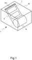
- Fig. 1 is a schematic perspective view showing the printer that houses roll paper according to the present embodiment.
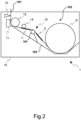
- Fig. 2 is a schematic side view showing an internal configuration of the printer according to the present embodiment.
- a printer 1 is a thermal printer.
- the printer 1 has a linerless label printing mode and a label printing mode as printing modes.
- the linerless label printing mode is a mode for printing on a linerless label sheet released from roll paper R.
- the label printing mode is a mode for performing printing on a label L attached to a base sheet S (label sheet) released from the roll paper R.
- the printing mode is changed, for example, by a user's operation in accordance with whether the roll paper R housed in the printer 1 is roll paper around which the linerless label sheet is wound or roll paper around which the base sheet S is wound.
- the printer 1 includes a casing 10, a printing head 11, a platen roller 12, a cutter 13, an auxiliary roller 14, a damper 15, and a limiter 16 (see Figs. 6 and 7 ).
- the casing 10 has a housing space 103 which is formed in a substantially box shape and houses the above-mentioned components and the roll paper R.
- the casing 10 includes, in a part of its upper surface, a delivery port 101 for delivering a printed sheet.
- the roll paper R shown in the figure is one with the base sheet S wound around a core (not shown) for example.
- the base sheet S is a continuous sheet to which a plurality of labels L are continuously attached at intervals.
- the label L is heat-sensitive paper with an adhesive applied to one surface.
- the side on which the label L is attached will be referred to as a top surface of the base sheet S.
- the back of the side on which the label L is attached will be referred to as a back surface of the base sheet S.
- the printing head 11 shown in Fig. 2 has a plurality of heat elements which is provided near the delivery port 101 and adjacent to each other in the width direction of the label L.
- the plurality of heat elements generates heat in accordance with input pulse waves. This configuration enables the printing head 11 to form (print) an image on the label L.
- the platen roller 12 is a feed roller provided so as to press the label L to the printing head 11 from the back of the base sheet S. By being driven to rotate, the platen roller 12 conveys the base sheet S released from the roll paper R so as to be delivered from the delivery port 101.
- the cutter 13 shown in Fig. 2 is provided nearer the delivery port 101 than the printing head 11, i.e., on a more downstream side in the conveying direction than the printing head 11.
- the cutter 13 cuts the base sheet S between a label L printed by the printing head 11 and a label L continuous to such a label L.
- the damper 15 shown in Fig. 2 is provided between the roll paper R and the platen roller 12 in the conveying direction for the base sheet S.
- the damper 15 applies a tensile force the base sheet S between the roll paper R and the platen roller 12 by pressing the base sheet S from the top surface. It should be noted that the damper 15 will be described later in detail together with the limiter 16.
- the auxiliary roller 14 shown in Fig. 2 is provided between the press position for the base sheet S by the damper 15 and the platen roller 12.
- the auxiliary roller 14 is held in contact with the back of the base sheet S pressed by the damper 15 and assists application of a tensile force by the damper 15.
- Figs. 3 and 4 are respectively an upper perspective view and a lower perspective view showing the configuration of the damper 15 according to the present embodiment.
- Fig. 5 is a schematic side view showing the damper 15 which is biased by extension springs 159 in the present embodiment.
- Figs. 6 and 7 are respectively a perspective view and a cross-sectional side view showing the damper 15 in a limited state according to the present embodiment.
- Fig. 8 is a schematic diagram showing the label sheet to which a tensile force is applied by the damper 15 in an unlimited state according to the present embodiment.
- FIG. 9 is a schematic diagram showing the label sheet to which no tensile force is applied by the damper in the limited state according to the present embodiment. It should be noted that for the sake of description, the limiter 16 is omitted from Fig. 5 and levers 152 are omitted from Fig. 7 .
- the damper 15 includes a main body 150, two roller groups 151, and two levers 152.
- the main body 150 is substantially plate-like member formed with a large width corresponding to the width of the base sheet S.
- the two roller groups 151 are provided, spaced apart from each other in the width direction, at one end portion in a direction orthogonal (orthogonal direction) to the width direction of the main body 150.
- the two roller groups 151 each have a plurality of rollers.
- the two levers 152 are provided, spaced apart from each other in the width direction, at the other end portion in the orthogonal direction of the main body 150.
- the main body 150 is provided to be capable of swinging around a rotation shaft C in the vicinity of the other end portion with respect to a bottom wall 102 forming the housing space 103 of the casing 10.
- the two levers 152 penetrate the bottom wall 102 forming the housing space 103 of the casing 10 in a state in which the main body 150 is attached within the casing 10.
- Two mounting portions 158 respectively corresponding to the two levers 152 are provided on the back side of the bottom wall 102, i.e., on a surface opposite to a surface on which the housing space 103 is formed.
- the two levers 152 are respectively coupled to the corresponding two mounting portions 158 through the extension springs 159. Accordingly, the damper 15 is constantly biased by the extension springs 159 so as to swing in the clockwise direction in Fig. 5 and presses the base sheet S between the auxiliary roller 14 and the roll paper R. At this time, the two roller groups 151 of the damper 15 are held in contact with the top surface of the base sheet S, and friction produced on the damper 15 and the base sheet S is accordingly reduced.
- the limiter 16 includes a locked portion 160 and a locking portion 161.
- the locked portion 160 is provided between the two roller groups 151 at the one end portion in the orthogonal direction in the main body 150 of the damper 15.
- the locked portion 160 is a step portion that engages with the locking portion 161 to be capable of locking the damper 15 when the damper 15 swings in a biasing direction of the extension springs 159.
- the locking portion 161 is a substantially plate-like member which is guided to be movable in the radial direction of the rotation shaft C by guide portions 162 formed as two slots opposite to each other in the width direction of the damper 15.
- the locking portion 161 protrudes towards the rotation shaft C from the guide portions 162 so as to be positioned on the side in the biasing direction of the extension springs 159 with respect to the guide portions 162.
- the locking portion 161 engages with the locked portion 160 and locks the damper 15 (see Fig. 7 ).
- the damper 15 enters the limited state in which the swing distance due to biasing of the extension springs 159 is limited so that the damper 15 does not press the base sheet S.
- the damper 15 enters the unlimited state in which the swing distance due to biasing of the extension springs 159 is not limited.
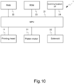
- FIG. 10 is a block diagram showing a configuration of the control system for the printer according to the present embodiment.
- the printer 1 shown in Fig. 10 includes a processor and a memory.
- the processor is, for example, a micro processor unit (MPU) 21.
- the memory is, for example, a random access memory (RAM) 22 and a read only memory (ROM) 23.
- the printer 1 further includes a communication I/F (interface) 24, a platen motor 31, and a solenoid 32.
- the platen motor 31 drives the platen roller 12 to rotate.
- the solenoid 32 linearly moves the locking portion 161 so as to protrude from the guide portions 162 (see the state shown in Fig. 7 ) or so as to be stored in the guide portions 162.
- the communication I/F 24 communicates with a superordinate device for the printer 1.
- the MPU 21 cooperates with the RAM 22, controls the printing head 11 and the platen motor 31, and forms (prints) an image received from the superordinate device on the label L.
- the MPU 21 sets the printer 1 on the linerless label printing mode or the label printing mode and performs state-switching processing to be described later.
- the ROM 23 stores programs and data used for the processing by the MPU 21.
- Fig. 11 is a flowchart showing the state-switching processing according to the present embodiment. It should be noted that the processing shown in Fig. 11 is performed in each predetermined cycle.
- Step S101 the MPU 21 determines whether or not the printing mode of the printer 1 has been changed. In a case where the MPU 21 determines that the printing mode has been changed (YES in S101), the processing of the MPU 21 proceeds to Step S102. In Step S102, the MPU 21 determines whether or not the printing mode has been changed to the label printing mode. On the other hand, in Step S101, in a case where the MPU 21 determines that the printing mode has not been changed (NO in S101), the MPU 21 terminates the state-switching processing shown in Fig. 11 .
- Step S102 in a case where the MPU 21 determines that the printing mode has been changed to the label printing mode (YES in S102), the processing of the MPU 21 proceeds to Step S103.
- Step S103 the MPU 21 controls the solenoid 32 to put the damper 15 in the limited state (e.g., see Fig. 9 ) so as to make the locking portion 161 project from the guide portions 162 (see Fig. 7 ).
- the MPU 21 terminates the state-switching processing shown in Fig. 11 .
- Step S102 in a case where the printing mode has not been changed to the label printing mode, i.e., in a case where the printing mode has been changed to the linerless label printing mode (NO in S102), the processing of the MPU 21 proceeds to Step S104.
- Step S104 the MPU 21 controls the solenoid 32 to put the damper 15 in the unlimited state so that the locking portion 161 is stored in the guide portions 162. After putting the damper 15 in the unlimited state, the MPU 21 terminates the state-switching processing shown in Fig. 11 .
- the printer 1 locks the damper 15 against a biasing force from the extension springs 159 so that no tensile force is applied to the base sheet S in order to put the damper 15 in the limited state. Therefore, in the printer 1, detachment of the label L due to the damper 15 can be prevented.
- the locking portion 161 is configured to be moved by the solenoid 32 in the above-mentioned embodiment, the locking portion 161 may be configured to be manually moved by the user of the printer 1.
- the printer 1 is configured to perform printing in a photosensitive manner, the printer 1 may be configured to perform printing in another manner.
- the damper 15 is not limited to one that swings, and for example, the damper 15 may be configured to linearly move the tip end portion for applying a tensile force to the base sheet S.
Landscapes
- Handling Of Continuous Sheets Of Paper (AREA)
- Registering, Tensioning, Guiding Webs, And Rollers Therefor (AREA)
Abstract
Description
- Embodiments described herein generally relate to a printer.
- Conventionally, a linerless label printer includes a damper. Although the linerless label sheet is released and fed from roll paper, a large force is required for separating the linerless label sheet from the roll paper. A damper that applies a tensile force to a sheet released from roll paper prevents a printing failure which would occur when the sheet cannot be suitably fed to a printing head. Moreover, the damper mechanism is also effective in a case of using roll paper with a large diameter, which requires a large force for releasing it due to the inertia.
- In a case where a label sheet with a label attached to a base sheet is used in a printer with such a damper mechanism, label detachment occurs. A cutter for cutting the label sheet is located on a more downstream side in the sheet conveying direction than the printing head. Therefore, in a case where the cutter is at a long distance from the printing head, after the label sheet is cut between a printed label and a label adjacent to the printed label, it is necessary to return the adjacent label to a position where the adjacent label can be printed. At this time, the label is in some cases detached at a position on the sheet which is curved by the damper.
- To this end, there is provided a printer according to
claim 1. - According to the invention, the printer may further comprise a processor that performs control for driving the limiter to switch the damper in the limited state in a case where a label sheet with a label attached to a base sheet is used as the continuous sheet.
- According to the invention, the processor may determine whether or not a mode to print the continuous sheet has been changed, in a case where the processor may determine that the mode to print has been changed, the processor may determine whether or not the mode to print is a label printing mode on which the label sheet is used, and in a case where the processor may determine that the mode to print is a label printing mode, control for driving the limiter is performed to switch the damper to the limited state.
- According to the invention, the damper may move towards the continuous sheet by the predetermined distance and may apply a tensile force to the continuous sheet on the conveying path on a more upstream side in the conveying direction than the printing head.
- According to the invention, the printer may further comprise an extension spring that moves towards the continuous sheet by the predetermined distance and biases the damper so as to apply a tensile force to the continuous sheet.
- According to the invention, the limiter may put the damper in the limited state by engaging the damper against a biasing force caused by the extension spring.
- According to the invention, the limiter may include a locked portion provided in the damper and a locking portion that locks the damper by engaging with the locked portion.
- According to the invention, the locking portion may be provided to be movable between a position at which the locking portion engages with the locked portion and a position at which the locking portion does not engage with the locked portion.
- According to the invention, the limiter may further include a guide portion, wherein in a case where the locking portion protrudes from the guide portion, the locking portion engages with the locked portion, and in a case where the locking portion is stored in the guide portion, the locking portion does not engage with the locked portion.
- According to the invention, the printer may further comprise a solenoid that moves the locking portion between the position at which the locking portion engages with the locked portion and the position at which the locking portion does not engage with the locked portion.
- According to the invention, the printer may further comprise a processor that controls the solenoid to move the damper. According to the invention, the printer may further comprise an auxiliary roller between the damper and the feed roller.
- According to the invention, the damper may comprise a main body, at least one lever and at least one roller.
- According to the invention, the at least one roller may be held in contact with the continuous sheet when the damper applies a tensile force to the continuous sheet.
- There is also provided a method for printing in a printer comprising a printing head that prints a continuous sheet released from a roll around which the continuous sheet is wound; a feed roller that conveys the continuous sheet via the printing head; and a damper that moves towards the continuous sheet by a predetermined distance and applies a tensile force to the continuous sheet on a conveying path for the continuous sheet conveyed by the feed roller; and a limiter that switches a state of the damper between an unlimited state in which a movement distance for the damper is not limited and a limited state in which the movement distance for the damper is limited so that no tensile force is applied to the continuous sheet, the method comprising:
- determining whether or not a mode to print the continuous sheet has been changed,
- in a case where it is determined that the mode to print has been changed, determining whether or not the mode to print is a label printing mode on which a label sheet is used, and
- in a case where it is determined that the mode to print is a label printing mode, performing control for driving the limiter to switch the damper to the limited state.
-
-
Fig. 1 is a schematic perspective view showing a printer that houses roll paper according to an embodiment. -
Fig. 2 is a schematic side view showing an internal configuration of the printer according to the embodiment. -
Fig. 3 is a perspective view showing an upper configuration of a damper according to the embodiment. -
Fig. 4 is a perspective view showing a lower configuration of a damper according to the embodiment. -
Fig. 5 is a schematic side view showing the damper biased by an extension spring according to the embodiment. -
Fig. 6 is a perspective view showing the damper in a limited state according to the embodiment. -
Fig. 7 is a side cross-sectional view showing the damper in the limited state according to the embodiment. -
Fig. 8 is a schematic diagram showing a label sheet to which a tensile force is applied by the damper in an unlimited state according to the embodiment. -
Fig. 9 is a schematic diagram showing the label sheet to which no tensile force is applied by the damper in the limited state according to the embodiment. -
Fig. 10 is a block diagram showing a configuration of a control system for the printer according to the embodiment. -
Fig. 11 is a flowchart showing state-switching processing according to the embodiment. - In accordance with one embodiment, a printer includes a print head, a feeding roller, a damper, and a limiter. The printing head prints a continuous sheet released from a roll around which the continuous sheet is wound. The feed roller conveys the continuous sheet via the printing head. The damper moves towards the continuous sheet by a predetermined distance and applies a tensile force to the continuous sheet on a conveying path for the continuous sheet conveyed by the feed roller. In addition, the limiter switches a state of the damper between an unlimited state in which a movement distance for the damper is not limited and a limited state in which the movement distance for the damper is limited so that no tensile force is applied to the continuous sheet.
- Hereinafter, embodiments will be described with reference to the drawings. In the drawings, the same configurations will be denoted by the same reference signs.
- A configuration of a printer according to the present embodiment will be described.
Fig. 1 is a schematic perspective view showing the printer that houses roll paper according to the present embodiment.Fig. 2 is a schematic side view showing an internal configuration of the printer according to the present embodiment. - As shown in
Figs. 1 and2 , aprinter 1 according to the present embodiment is a thermal printer. Theprinter 1 has a linerless label printing mode and a label printing mode as printing modes. The linerless label printing mode is a mode for printing on a linerless label sheet released from roll paper R. The label printing mode is a mode for performing printing on a label L attached to a base sheet S (label sheet) released from the roll paper R. The printing mode is changed, for example, by a user's operation in accordance with whether the roll paper R housed in theprinter 1 is roll paper around which the linerless label sheet is wound or roll paper around which the base sheet S is wound. As shown inFigs. 1 and2 , theprinter 1 includes acasing 10, aprinting head 11, aplaten roller 12, acutter 13, anauxiliary roller 14, adamper 15, and a limiter 16 (seeFigs. 6 and7 ). - The
casing 10 has ahousing space 103 which is formed in a substantially box shape and houses the above-mentioned components and the roll paper R. Thecasing 10 includes, in a part of its upper surface, adelivery port 101 for delivering a printed sheet. The roll paper R shown in the figure is one with the base sheet S wound around a core (not shown) for example. The base sheet S is a continuous sheet to which a plurality of labels L are continuously attached at intervals. The label L is heat-sensitive paper with an adhesive applied to one surface. In the following description, the side on which the label L is attached will be referred to as a top surface of the base sheet S. Moreover, the back of the side on which the label L is attached will be referred to as a back surface of the base sheet S. - The
printing head 11 shown inFig. 2 has a plurality of heat elements which is provided near thedelivery port 101 and adjacent to each other in the width direction of the label L. The plurality of heat elements generates heat in accordance with input pulse waves. This configuration enables theprinting head 11 to form (print) an image on the label L. Theplaten roller 12 is a feed roller provided so as to press the label L to theprinting head 11 from the back of the base sheet S. By being driven to rotate, theplaten roller 12 conveys the base sheet S released from the roll paper R so as to be delivered from thedelivery port 101. - The
cutter 13 shown inFig. 2 is provided nearer thedelivery port 101 than theprinting head 11, i.e., on a more downstream side in the conveying direction than theprinting head 11. Thecutter 13 cuts the base sheet S between a label L printed by theprinting head 11 and a label L continuous to such a label L. Thedamper 15 shown inFig. 2 is provided between the roll paper R and theplaten roller 12 in the conveying direction for the base sheet S. Thedamper 15 applies a tensile force the base sheet S between the roll paper R and theplaten roller 12 by pressing the base sheet S from the top surface. It should be noted that thedamper 15 will be described later in detail together with thelimiter 16. - The
auxiliary roller 14 shown inFig. 2 is provided between the press position for the base sheet S by thedamper 15 and theplaten roller 12. Theauxiliary roller 14 is held in contact with the back of the base sheet S pressed by thedamper 15 and assists application of a tensile force by thedamper 15. - Configurations of the
damper 15 and thelimiter 16 according to the present embodiment will be described.Figs. 3 and4 are respectively an upper perspective view and a lower perspective view showing the configuration of thedamper 15 according to the present embodiment.Fig. 5 is a schematic side view showing thedamper 15 which is biased by extension springs 159 in the present embodiment.Figs. 6 and7 are respectively a perspective view and a cross-sectional side view showing thedamper 15 in a limited state according to the present embodiment.Fig. 8 is a schematic diagram showing the label sheet to which a tensile force is applied by thedamper 15 in an unlimited state according to the present embodiment.Fig. 9 is a schematic diagram showing the label sheet to which no tensile force is applied by the damper in the limited state according to the present embodiment. It should be noted that for the sake of description, thelimiter 16 is omitted fromFig. 5 and levers 152 are omitted fromFig. 7 . - As shown in
Figs. 3 and4 , thedamper 15 includes amain body 150, tworoller groups 151, and twolevers 152. Themain body 150 is substantially plate-like member formed with a large width corresponding to the width of the base sheet S. The tworoller groups 151 are provided, spaced apart from each other in the width direction, at one end portion in a direction orthogonal (orthogonal direction) to the width direction of themain body 150. The tworoller groups 151 each have a plurality of rollers. - As shown in
Fig. 4 , the twolevers 152 are provided, spaced apart from each other in the width direction, at the other end portion in the orthogonal direction of themain body 150. Moreover, as shown inFig. 5 , themain body 150 is provided to be capable of swinging around a rotation shaft C in the vicinity of the other end portion with respect to abottom wall 102 forming thehousing space 103 of thecasing 10. The twolevers 152 penetrate thebottom wall 102 forming thehousing space 103 of thecasing 10 in a state in which themain body 150 is attached within thecasing 10. Two mountingportions 158 respectively corresponding to the twolevers 152 are provided on the back side of thebottom wall 102, i.e., on a surface opposite to a surface on which thehousing space 103 is formed. - As shown in
Fig. 5 , the twolevers 152 are respectively coupled to the corresponding two mountingportions 158 through the extension springs 159. Accordingly, thedamper 15 is constantly biased by the extension springs 159 so as to swing in the clockwise direction inFig. 5 and presses the base sheet S between theauxiliary roller 14 and the roll paper R. At this time, the tworoller groups 151 of thedamper 15 are held in contact with the top surface of the base sheet S, and friction produced on thedamper 15 and the base sheet S is accordingly reduced. - As shown in
Figs. 3 ,4 ,6 , and7 , thelimiter 16 includes a lockedportion 160 and a lockingportion 161. the lockedportion 160 is provided between the tworoller groups 151 at the one end portion in the orthogonal direction in themain body 150 of thedamper 15. The lockedportion 160 is a step portion that engages with the lockingportion 161 to be capable of locking thedamper 15 when thedamper 15 swings in a biasing direction of the extension springs 159. - As shown in
Figs. 6 and7 , the lockingportion 161 is a substantially plate-like member which is guided to be movable in the radial direction of the rotation shaft C byguide portions 162 formed as two slots opposite to each other in the width direction of thedamper 15. The lockingportion 161 protrudes towards the rotation shaft C from theguide portions 162 so as to be positioned on the side in the biasing direction of the extension springs 159 with respect to theguide portions 162. When protruding from theguide portions 162, the lockingportion 161 engages with the lockedportion 160 and locks the damper 15 (seeFig. 7 ). At this time, thedamper 15 enters the limited state in which the swing distance due to biasing of the extension springs 159 is limited so that thedamper 15 does not press the base sheet S. On the other hand, in a case where the lockingportion 161 is stored in theguide portions 162, does not engage with the lockedportion 160, and does not lock thedamper 15, thedamper 15 enters the unlimited state in which the swing distance due to biasing of the extension springs 159 is not limited. - In a case where the
damper 15 is in the unlimited state as shown inFig. 8 , the label L is detached near the press position by thedamper 15 when the base sheet S is moved by theplaten roller 12 in a direction opposite to theprinting head 11. On the other hand, in a case where thedamper 15 is in the limited state as shown inFig. 9 , detachment of the label L is prevented because thedamper 15 applies no tensile force to the base sheet S when the base sheet S is moved in the opposite direction. - Configuration and operation of a control system for the printer according to the present embodiment will be described.
Fig. 10 is a block diagram showing a configuration of the control system for the printer according to the present embodiment. - The
printer 1 shown inFig. 10 includes a processor and a memory. The processor is, for example, a micro processor unit (MPU) 21. The memory is, for example, a random access memory (RAM) 22 and a read only memory (ROM) 23. Moreover, theprinter 1 further includes a communication I/F (interface) 24, aplaten motor 31, and asolenoid 32. - The
platen motor 31 drives theplaten roller 12 to rotate. Thesolenoid 32 linearly moves the lockingportion 161 so as to protrude from the guide portions 162 (see the state shown inFig. 7 ) or so as to be stored in theguide portions 162. - The communication I/
F 24 communicates with a superordinate device for theprinter 1. TheMPU 21 cooperates with theRAM 22, controls theprinting head 11 and theplaten motor 31, and forms (prints) an image received from the superordinate device on the label L. In addition, theMPU 21 sets theprinter 1 on the linerless label printing mode or the label printing mode and performs state-switching processing to be described later. TheROM 23 stores programs and data used for the processing by theMPU 21. - The state-switching processing of the MPU 21 (processor) will be described.
Fig. 11 is a flowchart showing the state-switching processing according to the present embodiment. It should be noted that the processing shown inFig. 11 is performed in each predetermined cycle. - As shown in
Fig. 11 , in Step S101, theMPU 21 determines whether or not the printing mode of theprinter 1 has been changed. In a case where theMPU 21 determines that the printing mode has been changed (YES in S101), the processing of theMPU 21 proceeds to Step S102. In Step S102, theMPU 21 determines whether or not the printing mode has been changed to the label printing mode. On the other hand, in Step S101, in a case where theMPU 21 determines that the printing mode has not been changed (NO in S101), theMPU 21 terminates the state-switching processing shown inFig. 11 . - In Step S102, in a case where the
MPU 21 determines that the printing mode has been changed to the label printing mode (YES in S102), the processing of theMPU 21 proceeds to Step S103. In Step S103, theMPU 21 controls thesolenoid 32 to put thedamper 15 in the limited state (e.g., seeFig. 9 ) so as to make the lockingportion 161 project from the guide portions 162 (seeFig. 7 ). After putting thedamper 15 in the limited state, theMPU 21 terminates the state-switching processing shown inFig. 11 . - On the other hand, in Step S102, in a case where the printing mode has not been changed to the label printing mode, i.e., in a case where the printing mode has been changed to the linerless label printing mode (NO in S102), the processing of the
MPU 21 proceeds to Step S104. In Step S104, theMPU 21 controls thesolenoid 32 to put thedamper 15 in the unlimited state so that the lockingportion 161 is stored in theguide portions 162. After putting thedamper 15 in the unlimited state, theMPU 21 terminates the state-switching processing shown inFig. 11 . - In this manner, the
printer 1 locks thedamper 15 against a biasing force from the extension springs 159 so that no tensile force is applied to the base sheet S in order to put thedamper 15 in the limited state. Therefore, in theprinter 1, detachment of the label L due to thedamper 15 can be prevented. It should be noted that although the lockingportion 161 is configured to be moved by thesolenoid 32 in the above-mentioned embodiment, the lockingportion 161 may be configured to be manually moved by the user of theprinter 1. Moreover, although theprinter 1 is configured to perform printing in a photosensitive manner, theprinter 1 may be configured to perform printing in another manner. Moreover, thedamper 15 is not limited to one that swings, and for example, thedamper 15 may be configured to linearly move the tip end portion for applying a tensile force to the base sheet S. - While certain embodiments have been described, these embodiments have been presented by way of example only, and are not intended to limit the scope of the inventions. Indeed, the novel embodiments described herein may be embodied in a variety of other forms; furthermore, various omissions, substitutions and changes in the form of the embodiments described herein may be made without departing from the scope of the inventions. The accompanying claims are intended to cover such forms or modifications as would fall within the scope of the inventions.
Claims (15)
- A printer, comprising:a printing head (11) that prints a continuous sheet released from a roll around which the continuous sheet is wound;a feed roller (12) that conveys the continuous sheet via the printing head;a damper (15) that moves towards the continuous sheet by a predetermined distance and applies a tensile force to the continuous sheet on a conveying path for the continuous sheet conveyed by the feed roller; anda limiter (16) that switches a state of the damper between an unlimited state in which a movement distance for the damper is not limited and a limited state in which the movement distance for the damper is limited so that no tensile force is applied to the continuous sheet.
- The printer according to claim 1, further comprising
a processor (21) that performs control for driving the limiter to switch the damper in the limited state in a case where a label sheet with a label attached to a base sheet is used as the continuous sheet. - The printer according to claim 2, whereinthe processor determines whether or not a mode to print the continuous sheet has been changed,in a case where the processor determines that the mode to print has been changed, the processor determines whether or not the mode to print is a label printing mode on which the label sheet is used, andin a case where the processor determines that the mode to print is a label printing mode, control for driving the limiter is performed to switch the damper to the limited state.
- The printer according to any one of claims 1 to 3, wherein
the damper moves towards the continuous sheet by the predetermined distance and applies a tensile force to the continuous sheet on the conveying path on a more upstream side in the conveying direction than the printing head. - The printer according to any one of claims 1 to 4, further comprising
an extension spring (159) that moves towards the continuous sheet by the predetermined distance and biases the damper so as to apply a tensile force to the continuous sheet. - The printer according to claim 5, wherein
the limiter puts the damper in the limited state by engaging the damper against a biasing force caused by the extension spring. - The printer according to any one of claims 1 to 6, wherein
the limiter includesa locked portion (160) provided in the damper anda locking portion (161) that locks the damper by engaging with the locked portion. - The printer according to claim 7, wherein
the locking portion is provided to be movable between a position at which the locking portion engages with the locked portion and a position at which the locking portion does not engage with the locked portion. - The printer according to claim 7 or 8, whereinthe limiter further includes a guide portion (162),whereinin a case where the locking portion protrudes from the guide portion, the locking portion engages with the locked portion, andin a case where the locking portion is stored in the guide portion, the locking portion does not engage with the locked portion.
- The printer according to any one of claims 7 to 9, further comprising
a solenoid (32) that moves the locking portion between the position at which the locking portion engages with the locked portion and the position at which the locking portion does not engage with the locked portion. - The printer according to claim 10, further comprising
a processor that controls the solenoid to move the damper. - The printer according to any one of claims 1 to 11, further comprising
an auxiliary roller (14) between the damper and the feed roller. - The printer according to any one of claims 1 to 12, wherein the damper comprises a main body, at least one lever and at least one roller.
- The printer according to claim 13, wherein the at least one roller is held in contact with the continuous sheet when the damper applies a tensile force to the continuous sheet.
- A method for printing in a printer comprising a printing head that prints a continuous sheet released from a roll around which the continuous sheet is wound; a feed roller that conveys the continuous sheet via the printing head; and a damper that moves towards the continuous sheet by a predetermined distance and applies a tensile force to the continuous sheet on a conveying path for the continuous sheet conveyed by the feed roller; and a limiter that switches a state of the damper between an unlimited state in which a movement distance for the damper is not limited and a limited state in which the movement distance for the damper is limited so that no tensile force is applied to the continuous sheet, the method comprising:determining whether or not a mode to print the continuous sheet has been changed,in a case where it is determined that the mode to print has been changed, determining whether or not the mode to print is a label printing mode on which a label sheet is used, andin a case where it is determined that the mode to print is a label printing mode, performing control for driving the limiter to switch the damper to the limited state.
Applications Claiming Priority (1)
| Application Number | Priority Date | Filing Date | Title |
|---|---|---|---|
| JP2023071613A JP7811923B2 (en) | 2023-04-25 | 2023-04-25 | printer |
Publications (2)
| Publication Number | Publication Date |
|---|---|
| EP4454892A1 true EP4454892A1 (en) | 2024-10-30 |
| EP4454892B1 EP4454892B1 (en) | 2026-06-17 |
Family
ID=89767487
Family Applications (1)
| Application Number | Title | Priority Date | Filing Date |
|---|---|---|---|
| EP24154237.2A Active EP4454892B1 (en) | 2023-04-25 | 2024-01-26 | Printer |
Country Status (4)
| Country | Link |
|---|---|
| US (1) | US12583243B2 (en) |
| EP (1) | EP4454892B1 (en) |
| JP (1) | JP7811923B2 (en) |
| CN (1) | CN118832966A (en) |
Families Citing this family (1)
| Publication number | Priority date | Publication date | Assignee | Title |
|---|---|---|---|---|
| JP7811922B2 (en) * | 2023-04-25 | 2026-02-06 | 東芝テック株式会社 | printer |
Citations (3)
| Publication number | Priority date | Publication date | Assignee | Title |
|---|---|---|---|---|
| JPH08151149A (en) * | 1994-11-29 | 1996-06-11 | Tec Corp | Printer |
| JP2000016651A (en) * | 1998-06-30 | 2000-01-18 | Toshiba Tec Corp | Receipt printer |
| US20190152240A1 (en) * | 2016-09-06 | 2019-05-23 | Toshiba Tec Kabushiki Kaisha | Print unit and printer |
Family Cites Families (14)
| Publication number | Priority date | Publication date | Assignee | Title |
|---|---|---|---|---|
| JP2908713B2 (en) * | 1994-11-30 | 1999-06-21 | 東芝テック株式会社 | Label printer |
| IT1321127B1 (en) * | 2000-12-20 | 2003-12-30 | Olivetti Lexikon Spa | DEVICE FOR THE INTERMITTENT ADVANCE OF A CARTADA STRIP A ROLL. |
| JP4399151B2 (en) * | 2002-09-18 | 2010-01-13 | 武藤工業株式会社 | Winding device for recording device |
| JP2004155533A (en) * | 2002-11-05 | 2004-06-03 | Fuji Xerox Co Ltd | Continuous paper conveyance mechanism and printing device having it |
| JP2005238752A (en) * | 2004-02-27 | 2005-09-08 | Sato Corp | Printer |
| JP4886050B2 (en) | 2009-02-10 | 2012-02-29 | 東芝テック株式会社 | Label printer |
| JP5518170B2 (en) * | 2012-12-25 | 2014-06-11 | 株式会社ミマキエンジニアリング | Inkjet printer |
| JP6664051B2 (en) * | 2015-11-05 | 2020-03-13 | サトーホールディングス株式会社 | Printer |
| JP6895447B2 (en) * | 2016-10-04 | 2021-06-30 | サトーホールディングス株式会社 | Printer |
| JP2019006603A (en) * | 2017-06-28 | 2019-01-17 | 株式会社沖データ | Winding device |
| JP6908893B2 (en) * | 2018-03-20 | 2021-07-28 | ブラザー工業株式会社 | Printing equipment |
| CN211031767U (en) * | 2019-09-02 | 2020-07-17 | 商丘师范学院 | An inkjet art printing device |
| CN217947028U (en) * | 2022-07-19 | 2022-12-02 | 雷特玛(合肥)感压粘合涂层材料有限公司 | Be used for multi-functional food label material tension testing platform of compound polymer |
| CN218807180U (en) * | 2022-11-30 | 2023-04-07 | 苏州澄富自动化设备有限公司 | Label base paper rewinding mechanism and intelligent labeling equipment |
-
2023
- 2023-04-25 JP JP2023071613A patent/JP7811923B2/en active Active
-
2024
- 2024-01-04 US US18/403,888 patent/US12583243B2/en active Active
- 2024-01-26 EP EP24154237.2A patent/EP4454892B1/en active Active
- 2024-03-18 CN CN202410306669.7A patent/CN118832966A/en active Pending
Patent Citations (3)
| Publication number | Priority date | Publication date | Assignee | Title |
|---|---|---|---|---|
| JPH08151149A (en) * | 1994-11-29 | 1996-06-11 | Tec Corp | Printer |
| JP2000016651A (en) * | 1998-06-30 | 2000-01-18 | Toshiba Tec Corp | Receipt printer |
| US20190152240A1 (en) * | 2016-09-06 | 2019-05-23 | Toshiba Tec Kabushiki Kaisha | Print unit and printer |
Also Published As
| Publication number | Publication date |
|---|---|
| EP4454892B1 (en) | 2026-06-17 |
| JP2024157317A (en) | 2024-11-07 |
| US20240359490A1 (en) | 2024-10-31 |
| CN118832966A (en) | 2024-10-25 |
| US12583243B2 (en) | 2026-03-24 |
| JP7811923B2 (en) | 2026-02-06 |
Similar Documents
| Publication | Publication Date | Title |
|---|---|---|
| US6217017B1 (en) | Paper-feeding apparatus and method of feeding paper | |
| EP0733482A2 (en) | A cassette for a thermal printer | |
| JP7283114B2 (en) | Cutter device and printing device | |
| JP2002144655A (en) | Printer | |
| US12583243B2 (en) | Printer | |
| EP0120043B1 (en) | Record member feeding mechanism | |
| US5152623A (en) | Printer accommodating two types of printing sheets | |
| HK1006443B (en) | Printer accomodating two types of printing sheet | |
| JP3167982B2 (en) | Paper feeder for image forming apparatus | |
| GB2295584A (en) | A printer having a cutting device wherein the cutting device may be coupled to and decoupled from a printhead carriage | |
| EP4454893A1 (en) | Printer | |
| US20140255076A1 (en) | Printer apparatus and method for printing and discharging a rolled paper | |
| JPH07115774B2 (en) | Paper transport device | |
| EP4389440B1 (en) | Printer | |
| JP4981545B2 (en) | Printer | |
| US20230150160A1 (en) | Cutter unit and printer | |
| JP2002326735A (en) | Transport roller mechanism of image forming apparatus | |
| JP2003025662A (en) | Printers that use roll paper | |
| JPH08142443A (en) | Thermal transfer printer | |
| JP2008210097A (en) | Receipt print issuing device | |
| JPH0395038A (en) | Paper feeding tray | |
| JPS6260725A (en) | Paper feeder for printer | |
| JPH0755076Y2 (en) | Paper cutting device for register printer | |
| JPH0524528Y2 (en) | ||
| JP2001105686A (en) | Printing device |
Legal Events
| Date | Code | Title | Description |
|---|---|---|---|
| PUAI | Public reference made under article 153(3) epc to a published international application that has entered the european phase |
Free format text: ORIGINAL CODE: 0009012 |
|
| STAA | Information on the status of an ep patent application or granted ep patent |
Free format text: STATUS: THE APPLICATION HAS BEEN PUBLISHED |
|
| AK | Designated contracting states |
Kind code of ref document: A1 Designated state(s): AL AT BE BG CH CY CZ DE DK EE ES FI FR GB GR HR HU IE IS IT LI LT LU LV MC ME MK MT NL NO PL PT RO RS SE SI SK SM TR |
|
| STAA | Information on the status of an ep patent application or granted ep patent |
Free format text: STATUS: REQUEST FOR EXAMINATION WAS MADE |
|
| 17P | Request for examination filed |
Effective date: 20250430 |
|
| GRAP | Despatch of communication of intention to grant a patent |
Free format text: ORIGINAL CODE: EPIDOSNIGR1 |
|
| STAA | Information on the status of an ep patent application or granted ep patent |
Free format text: STATUS: GRANT OF PATENT IS INTENDED |
|
| INTG | Intention to grant announced |
Effective date: 20260113 |
|
| GRAS | Grant fee paid |
Free format text: ORIGINAL CODE: EPIDOSNIGR3 |
|
| GRAA | (expected) grant |
Free format text: ORIGINAL CODE: 0009210 |
|
| STAA | Information on the status of an ep patent application or granted ep patent |
Free format text: STATUS: THE PATENT HAS BEEN GRANTED |
|
| AK | Designated contracting states |
Kind code of ref document: B1 Designated state(s): AL AT BE BG CH CY CZ DE DK EE ES FI FR GB GR HR HU IE IS IT LI LT LU LV MC ME MK MT NL NO PL PT RO RS SE SI SK SM TR |
|
| REG | Reference to a national code |
Ref country code: CH Ref legal event code: F10 Free format text: ST27 STATUS EVENT CODE: U-0-0-F10-F00 (AS PROVIDED BY THE NATIONAL OFFICE) Effective date: 20260617 Ref country code: GB Ref legal event code: FG4D |
|
| REG | Reference to a national code |
Ref country code: DE Ref legal event code: R096 Ref document number: 602024005416 Country of ref document: DE |
|
| REG | Reference to a national code |
Ref country code: IE Ref legal event code: FG4D |