EP4454890A1 - Printer apparatus - Google Patents
Printer apparatus Download PDFInfo
- Publication number
- EP4454890A1 EP4454890A1 EP24154218.2A EP24154218A EP4454890A1 EP 4454890 A1 EP4454890 A1 EP 4454890A1 EP 24154218 A EP24154218 A EP 24154218A EP 4454890 A1 EP4454890 A1 EP 4454890A1
- Authority
- EP
- European Patent Office
- Prior art keywords
- ink ribbon
- printer apparatus
- heat
- transfer printer
- winding reel
- Prior art date
- Legal status (The legal status is an assumption and is not a legal conclusion. Google has not performed a legal analysis and makes no representation as to the accuracy of the status listed.)
- Granted
Links
Images


Classifications
-
- B—PERFORMING OPERATIONS; TRANSPORTING
- B41—PRINTING; LINING MACHINES; TYPEWRITERS; STAMPS
- B41J—TYPEWRITERS; SELECTIVE PRINTING MECHANISMS, i.e. MECHANISMS PRINTING OTHERWISE THAN FROM A FORME; CORRECTION OF TYPOGRAPHICAL ERRORS
- B41J2/00—Typewriters or selective printing mechanisms characterised by the printing or marking process for which they are designed
- B41J2/315—Typewriters or selective printing mechanisms characterised by the printing or marking process for which they are designed characterised by selective application of heat to a heat sensitive printing or impression-transfer material
- B41J2/32—Typewriters or selective printing mechanisms characterised by the printing or marking process for which they are designed characterised by selective application of heat to a heat sensitive printing or impression-transfer material using thermal heads
- B41J2/325—Typewriters or selective printing mechanisms characterised by the printing or marking process for which they are designed characterised by selective application of heat to a heat sensitive printing or impression-transfer material using thermal heads by selective transfer of ink from ink carrier, e.g. from ink ribbon or sheet
-
- B—PERFORMING OPERATIONS; TRANSPORTING
- B41—PRINTING; LINING MACHINES; TYPEWRITERS; STAMPS
- B41J—TYPEWRITERS; SELECTIVE PRINTING MECHANISMS, i.e. MECHANISMS PRINTING OTHERWISE THAN FROM A FORME; CORRECTION OF TYPOGRAPHICAL ERRORS
- B41J33/00—Apparatus or arrangements for feeding ink ribbons or like character-size impression-transfer material
- B41J33/02—Ribbon arrangements
- B41J33/06—Ribbons associated, but not moving, with typewriter platens, e.g. extending transversely to the length of the platen
-
- B—PERFORMING OPERATIONS; TRANSPORTING
- B41—PRINTING; LINING MACHINES; TYPEWRITERS; STAMPS
- B41J—TYPEWRITERS; SELECTIVE PRINTING MECHANISMS, i.e. MECHANISMS PRINTING OTHERWISE THAN FROM A FORME; CORRECTION OF TYPOGRAPHICAL ERRORS
- B41J2/00—Typewriters or selective printing mechanisms characterised by the printing or marking process for which they are designed
- B41J2/315—Typewriters or selective printing mechanisms characterised by the printing or marking process for which they are designed characterised by selective application of heat to a heat sensitive printing or impression-transfer material
-
- B—PERFORMING OPERATIONS; TRANSPORTING
- B41—PRINTING; LINING MACHINES; TYPEWRITERS; STAMPS
- B41J—TYPEWRITERS; SELECTIVE PRINTING MECHANISMS, i.e. MECHANISMS PRINTING OTHERWISE THAN FROM A FORME; CORRECTION OF TYPOGRAPHICAL ERRORS
- B41J17/00—Mechanisms for manipulating page-width impression-transfer material, e.g. carbon paper
- B41J17/28—Arrangements of guides for the impression-transfer material
-
- B—PERFORMING OPERATIONS; TRANSPORTING
- B41—PRINTING; LINING MACHINES; TYPEWRITERS; STAMPS
- B41J—TYPEWRITERS; SELECTIVE PRINTING MECHANISMS, i.e. MECHANISMS PRINTING OTHERWISE THAN FROM A FORME; CORRECTION OF TYPOGRAPHICAL ERRORS
- B41J17/00—Mechanisms for manipulating page-width impression-transfer material, e.g. carbon paper
- B41J17/30—Constructions of guides for the impression-transfer material
-
- B—PERFORMING OPERATIONS; TRANSPORTING
- B41—PRINTING; LINING MACHINES; TYPEWRITERS; STAMPS
- B41J—TYPEWRITERS; SELECTIVE PRINTING MECHANISMS, i.e. MECHANISMS PRINTING OTHERWISE THAN FROM A FORME; CORRECTION OF TYPOGRAPHICAL ERRORS
- B41J33/00—Apparatus or arrangements for feeding ink ribbons or like character-size impression-transfer material
- B41J33/003—Ribbon spools
-
- B—PERFORMING OPERATIONS; TRANSPORTING
- B41—PRINTING; LINING MACHINES; TYPEWRITERS; STAMPS
- B41J—TYPEWRITERS; SELECTIVE PRINTING MECHANISMS, i.e. MECHANISMS PRINTING OTHERWISE THAN FROM A FORME; CORRECTION OF TYPOGRAPHICAL ERRORS
- B41J33/00—Apparatus or arrangements for feeding ink ribbons or like character-size impression-transfer material
- B41J33/14—Ribbon-feed devices or mechanisms
-
- B—PERFORMING OPERATIONS; TRANSPORTING
- B41—PRINTING; LINING MACHINES; TYPEWRITERS; STAMPS
- B41J—TYPEWRITERS; SELECTIVE PRINTING MECHANISMS, i.e. MECHANISMS PRINTING OTHERWISE THAN FROM A FORME; CORRECTION OF TYPOGRAPHICAL ERRORS
- B41J35/00—Other apparatus or arrangements associated with, or incorporated in, ink-ribbon mechanisms
- B41J35/04—Ink-ribbon guides
- B41J35/06—Ink-ribbon guides stationary
-
- B—PERFORMING OPERATIONS; TRANSPORTING
- B41—PRINTING; LINING MACHINES; TYPEWRITERS; STAMPS
- B41J—TYPEWRITERS; SELECTIVE PRINTING MECHANISMS, i.e. MECHANISMS PRINTING OTHERWISE THAN FROM A FORME; CORRECTION OF TYPOGRAPHICAL ERRORS
- B41J2202/00—Embodiments of or processes related to ink-jet or thermal heads
- B41J2202/30—Embodiments of or processes related to thermal heads
- B41J2202/31—Thermal printer with head or platen movable
Definitions
- Embodiments described herein generally relate to a printer apparatus.
- a printer apparatus with a torque limiter for cancelling a conveying speed difference between an ink ribbon and a print sheet and winding up the ink ribbon while applying a predetermined tensile force to the ink ribbon has been proposed.
- the conveyance of the print sheet and the conveyance of the ink ribbon are performed with a driving force from another driving source.
- the conveyance of the print sheet and the conveyance of the ink ribbon are performed with a driving force from a single driving source.
- the ink ribbon is sometimes loosened due to the inertia force of a winding reel for the ink ribbon.
- the next print is started in a state in which the ink ribbon is loosened, the ink ribbon is suddenly pulled. A large impact is transmitted to a nip region where the print sheet is held in contact with a platen roller. This lowers the print quality at the print start, which is problematic.
- a heat-transfer printer apparatus includes a single driving source, a print head, a platen roller, a winding reel, a guide member, and an elastic member.
- the single driving source generates a driving force for conveying a print sheet and an ink ribbon.
- the printing head performs printing on the print sheet conveyed by the driving force by heating the ink ribbon conveyed by the driving force.
- the platen roller is provided in opposite to the printing head and conveys the ink ribbon and the print sheet overlapping each other while nipping the ink ribbon and the print sheet between the platen roller and the printing head.
- the winding reel winds up the ink ribbon after the printing.
- the guide member guides the ink ribbon and the print sheet nipped by the printing head and the platen roller and guides only the ink ribbon after the printing towards the winding reel.
- the elastic member is attached to a surface of the guide member, the surface guiding only the ink ribbon towards the winding reel.
- FIG. 1 is a diagram showing an example of a schematic configuration of the printer apparatus according to the first embodiment.
- the printer apparatus 10 is a so-called thermal heat-transfer printer that performs printing on a print sheet 15 by heating an ink ribbon 22.
- the printer apparatus 10 performs printing while pulling out the print sheet 15 from roll paper 14, around which the print sheet 15 is wound in the form of a roll, in the arrow E direction.
- the roll paper 14 is rotatably supported around a shaft 141 along a Y-axis in Fig. 1 .
- the print sheet 15 is, for example, a label sheet or a tag sheet.
- the label sheet has a structure in which a plurality of same-size labels is arranged at predetermined intervals on a base sheet.
- the label may have an adhesive layer formed on its back surface and be attached to a base sheet which is release paper so that the label can be released from the base sheet.
- the tag sheet is, for example, thick paper used as a product price tag or a baggage tag.
- the print sheet 15 pulled out from the roll paper 14 is put on a sheet guide 29, changes the direction, and overlaps the ink ribbon 22 pulled out in the arrow C direction from a ribbon roll 21. Then, the print sheet 15 is nipped by a thermal head 24 and a platen roller 25 rotating in the arrow B direction. Accordingly, a nip region where the thermal head 24, the ink ribbon 22, and the print sheet 15 are in contact is formed.
- the ribbon roll 21 is rotatably supported around an axis 211 along the Y-axis in Fig. 1 .
- the platen roller 25 is rotatably supported around a shaft 251 along the Y-axis in Fig. 1 .
- the thermal head 24 includes a plurality of heat elements.
- the thermal head 24 selectively heats the heat elements, thereby melting ink applied to the ink ribbon 22. Then, the molten ink is transferred to the print sheet 15. In this manner, for example, a desired characters or barcode is printed.
- the thermal head 24 is supported on a surface of a head frame 26 along the X-axis direction.
- the head frame 26 guides the ink ribbon 22 and the print sheet 15 nipped by the thermal head 24 and the platen roller 25. Specifically, the surface of the head frame 26 along the X-axis direction is held in contact with a surface of the ink ribbon 22, which is not held in contact with the print sheet 15, and guides the ink ribbon 22 and the print sheet 15.
- the head frame 26 is an example of a guide member in the present embodiment.
- the print sheet 15 after the printing is completed passes beyond the head frame 26, and then is guided by a pair of conveying rollers 16 and delivered from a delivery port 17.
- the print sheet 15 delivered from the delivery port 17 may be manually cut at the position of the delivery port 17 or may be cut by a cutter (not shown) placed near the delivery port 17.
- the ink ribbon 22 after the printing is completed is guided towards a winding reel 23 by a side surface of the head frame 26 on a positive side on the X-axis.
- the side surface of the head frame 26 on the positive side on the X-axis extends in a Z-axis direction.
- the side surface on the positive side on the X-axis is a surface in a direction (Z-axis direction) perpendicular to a conveying direction for the ink ribbon guided by the surface along the X-axis direction. Therefore, the conveying direction for the ink ribbon 22 is changed upwards by about 90 degrees on the side surface.
- the winding reel 23 rotatably supported around a shaft 231 along the Y-axis in Fig.
- An ethylene propylene diene monomer (EPDM) rubber sheet 40 is attached to the side surface of the head frame 26 on the positive side on the X-axis.
- the EPDM rubber sheet 40 is a synthetic rubber obtained by co-polymerizing ethylene and propylene and is molded in the form of a sheet (in the form of a plane).
- the EPDM rubber sheet 40 is attached to the side surface of the head frame 26 with an adhesive or a double sided tape, for example. Therefore, the back side of the ink ribbon 22 (side not held in contact with the print sheet 15) moves to the winding reel 23 via a wind-up portion R shown in Fig. 1 while sliding with the EPDM rubber sheet 40.
- the EPDM rubber sheet 40 is an example of an elastic member in the present embodiment. It should be noted that the EPDM rubber sheet 40 may be replaced by another elastic member having substantially the same hardness and thickness as the EPDM rubber sheet 40.
- a single driving motor 31 performs the conveyance of the print sheet 15 and the conveyance of the ink ribbon 22. It should be noted that the driving motor 31 is an example of a driving source in the present embodiment.
- a driving gear 32 directly coupled to an output shaft 311 of the driving motor 31 rotates in the arrow A direction.
- the rotation of the driving gear 32 is transmitted to a platen roller driving gear 34 directly coupled to the shaft 251 of the platen roller 25 via a coupling gear 33 meshing with the driving gear 32.
- the rotation of the platen roller driving gear 34 is transmitted to a coupling gear 36 meshing with the coupling gear 35 via a coupling gear 35 meshing with the platen roller driving gear 34.
- a ribbon roll driving gear 37 and a winding reel driving gear 38 mesh with the coupling gear 36. Therefore, along with rotation of the platen roller 25 in the arrow B direction, the ribbon roll 21 rotates in the arrow C direction and the winding reel 23 rotates in the arrow D direction.
- the platen roller driving gear 34 rotates the platen roller 25 in the arrow B direction. Then, with the rotation of the platen roller 25, the printing is performed while the print sheet 15 and the ink ribbon 22 nipped by the platen roller 25 and the thermal head 24 are conveyed in a positive direction on the X-axis. It should be noted that the diameter and the number of teeth for each gear are set so that the conveying speed for the ink ribbon 22 is equal to or higher than that for the platen roller 25 in order not to loosen the ink ribbon 22 when the printing is performed.
- the print sheet 15 is further conveyed (fed) in the positive direction on the X-axis and delivered from the delivery port 17. Moreover, the ink ribbon 22 is wound up by the winding reel 23.
- the printed print sheet 15 delivered from the delivery port 17 is cut, and then the printer apparatus 10 performs backfeed for returning the print sheet 15 to the next print start location.
- the driving motor 31 rotates in a direction opposite to the direction when performing the printing. That is, the driving gear 32 rotates in a direction opposite to the arrow A.
- the platen roller 25, the ribbon roll 21, and the winding reel 23 all rotate in the direction opposite to the direction when performing the printing. Accordingly, the print sheet 15 and the ink ribbon 22 are conveyed in a negative direction on the X-axis.
- the printer apparatus 10 includes a label gap detection sensor 28 and a tag sheet detection sensor 30 for detecting the position of the print sheet 15.
- the label gap detection sensor 28 is a transmissive optical sensor. In a case where a label sheet is used as the print sheet 15, the label gap detection sensor 28 detects a timing mark shown at a label gap position on the back side on a print surface of the label sheet.
- the tag sheet detection sensor 30 is a reflective optical sensor. In a case where a tag sheet is used as the print sheet 15, the tag sheet detection sensor 30 detects a timing mark shown at the back of a print surface of the tag sheet.
- Those sensors operate in accordance with the type of print sheet 15, which is set before the print start.
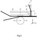
- Fig. 2 is a first diagram showing an example of a detailed structure in the periphery of the head frame 26 in the printer apparatus 10 according to the first embodiment.
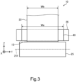
- Fig. 3 is a second diagram showing an example of a detailed structure in the periphery of the head frame 26 in the printer apparatus 10 according to the first embodiment.
- the ink ribbon 22 after the printing is conveyed in the positive direction on the X-axis along the head frame 26, changes the direction upwards by substantially 90 degrees, and is conveyed in a positive direction on the Z-axis along the EPDM rubber sheet 40.
- the ink ribbon 22 is conveyed while sliding on the surface of the EPDM rubber sheet 40.
- the ink ribbon 22 changes the direction by an angle of refraction ⁇ at a point P and moves towards the winding reel 23 (see Fig. 1 ).
- the angle of refraction ⁇ is an angle of refraction with respect to the conveying direction for the ink ribbon guided by the side surface in the positive direction on the X-axis.
- the point P is a position spaced apart from the side surface of the head frame 26 by a rubber thickness t of the EPDM rubber sheet 40.
- the angle of refraction ⁇ depends on the amount of the ink ribbon 22 wound up by the winding reel 23
- a positional relation between the shaft 231 of the winding reel 23 and the head frame 26 is set so that ⁇ > 0 degrees is constantly established irrespective of the amount of the ink ribbon 22 wound up by the winding reel 23. Therefore, the ink ribbon 22 is constantly pushed against the point P.
- the ink ribbon 22 When the ink ribbon 22 is backfed, there is a case where the ink ribbon 22 is not uniformly rewound in the region of the wind-up portion R shown in Fig. 1 because of clearances (backlash) provided in portions where the above-mentioned various gears mesh each other. In such a case, the ink ribbon 22 is loosened in the wind-up portion R. In particular, when the backfeed is performed in a case where the amount of ink ribbon 22 wound up around the winding reel 23 is larger, the ink ribbon 22 is more easily loosened because the inertia force of the winding reel 23 increases as compared to a case where the amount of ink ribbon 22 wound-up is smaller.
- a width Wa of the EPDM rubber sheet 40 in a direction orthogonal to the conveying direction for the ink ribbon 22 is set to be larger than a width Wb of the ink ribbon 22.
- both end portions of the EPDM rubber sheet 40 project from both end portions of the ink ribbon 22 in the width direction. Accordingly, the entire surface of the ink ribbon 22 is held in contact with the EPDM rubber sheet 40 on the side surface of the head frame 26.
- the ink ribbon 22 can be slid in a state in which the back surface of the ink ribbon 22 is reliably held in contact with the EPDM rubber sheet 40 even if the ink ribbon 22 is meandering.
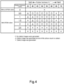
- FIG. 4 is a diagram showing an example of a result of assessing a relation between the type of elastic member and the print quality.
- Primary design parameters for the EPDM rubber sheet 40 used in the printer apparatus 10 according to the present embodiment are rubber hardness H and the rubber thickness t.
- the rubber hardness H is measured by pushing a measurement tool called durometer against a test sample and measuring how far an indenter travels in the test sample with a constant force applied on the indenter.
- the measurement result is expressed by degrees. The smaller the degrees are, the softer the test sample is.
- hardness 100 degrees indicates hardness like a glass and a general rubber hardness ranges from approximately 40 degrees to 70 degrees.
- the rubber thickness t is the thickness of the EPDM rubber sheet 40.
- the inventor of the present embodiment assessed the print quality of the printer apparatus 10 by using a plurality of EPDM rubber sheets 40 different in the rubber hardness H and the rubber thickness t. Moreover, the inventor compared it with the print quality with no EPDM rubber sheet 40.
- Fig. 4 shows an example of assessment results.
- the inventor has found that it is desirable that the rubber hardness H of the EPDM rubber sheet 40 ranges from 45 degrees to 65 degrees.
- the inventor has found that in a case where the rubber hardness H is lower (softer) than 45 degrees, silicon applied to the back of the ink ribbon 22 in order to improve its sliding ability sticks to the surface of the EPDM rubber sheet 40. Further, the inventor has found that the silicon sticking to the surface of the EPDM rubber sheet 40 makes the EPDM rubber sheet 40 slipperier, which reduces the impact absorbing effect when the ink ribbon 22 is suddenly pulled, applying a high tensile force, and leads to lowering of the print quality.
- the inventor has found that in a case where the rubber hardness H is higher (harder) than 65 degrees, it reduces the impact absorbing effect when the ink ribbon 22 is suddenly pulled, applying a high tensile force, and leads to lowering of the print quality.
- the inventor has found that it is desirable that the rubber thickness t of the EPDM rubber sheet 40 range from 0.5 mm to 2.0 mm.
- the thickness be at least equal to or larger than 0.5 mm.
- the rubber thickness t of the EPDM rubber sheet 40 is larger than 2.0 mm, the ink ribbon 22 largely deflects the EPDM rubber sheet 40 when a tensile force is applied to the ink ribbon 22 in a region where the rubber hardness H of the EPDM rubber sheet 40 is smaller (softer). Then, the ink ribbon 22 held in contact with the thermal head 24 is pulled, which leads to lowering of the print quality.
- the inventor has found that regarding a region where the rubber thickness t is equal to or larger than 2.0 mm, it is a combined region where a relation between the rubber thickness t and the hardness of the EPDM rubber sheet 40 is unstable, so the rubber thickness t is desirably equal to or smaller than 2.0 mm.
- the printer apparatus 10 is a heat-transfer printer apparatus with the thermal head 24 (printing head) that performs printing on the print sheet 15 by heating the ink ribbon 22, including the single driving motor 31 (driving source), the head frame 26 (guide member), and the EPDM rubber sheet 40 (elastic member).
- the single driving motor 31 generates a driving force for conveying the print sheet 15 and the ink ribbon 22.
- the head frame 26 supports the thermal head 24 and guides the ink ribbon 22 and the print sheet 15 nipped by the thermal head 24 and the platen roller 25 and guides the ink ribbon 22 after the printing towards the winding reel 23.
- the EPDM rubber sheet 40 is a sheet-like member attached to a surface of the side surfaces of the head frame 26, which are held in contact with the ink ribbon 22, the surface guiding the ink ribbon 22 after the printing towards the winding reel 23. Therefore, the EPDM rubber sheet 40 absorbs the impact when the ink ribbon 22 is suddenly pulled at the print start. Therefore, lowering of the print quality due to the ink ribbon 22 loosened during the backfeed can be prevented with a simple structure.
- the width Wa of the EPDM rubber sheet 40 (elastic member) in the direction orthogonal to the conveying direction for the ink ribbon 22 is larger than the width Wb of the ink ribbon 22. Therefore, the ink ribbon 22 can be slid in a state in which the back surface of the ink ribbon 22 is reliably held in contact with the EPDM rubber sheet 40 even if the ink ribbon 22 is meandering.
- the rubber hardness H of the EPDM rubber sheet 40 ranges from 45 degrees to 60 degrees
- the rubber thickness t of the EPDM rubber sheet 40 ranges from 0.5 mm to 2.0 mm. Therefore, lowering of the print quality due to the ink ribbon 22 loosened during the backfeed can be prevented.
- the elastic member is the EPDM rubber sheet 40. Therefore, since the EPDM rubber sheet 40 absorbs the impact when the ink ribbon 22 is suddenly pulled at the print start. Thus, lowering of the print quality due to the ink ribbon 22 loosened during the backfeed can be prevented with a simple structure.
- Fig. 5 is a diagram showing an example of a schematic configuration of the printer apparatus according to the second embodiment.
- the printer apparatus 11 shown in Fig. 5 includes a head frame 27 instead of the head frame 26 of the printer apparatus 10 described above in the first embodiment. It should be noted that operations of the respective parts of the printer apparatus 11 are similar to those of the printer apparatus 10 described above, so duplicate descriptions will be omitted and only differences from the printer apparatus 10 will be described below.
- the head frame 27 keeps the thermal head 24 in contact with the platen roller 25.
- the head frame 27 is an example of the guide member in the present embodiment.
- the ink ribbon 22 after the printing is completed is guided by a side surface of the head frame 27 on a positive side on the X-axis and moves towards the winding reel 23.
- the side surface on the positive side on the X-axis is a surface tilting in a conveying direction for the ink ribbon 22 from a surface in a direction (Z-axis direction) perpendicular to a conveying direction for the ink ribbon conveyed while being guided by the surface along the X-axis direction.
- the conveying direction for the ink ribbon 22 is changed to obliquely upper right in Fig. 5 .
- the winding reel 23 rotatably supported around a shaft 231 along the Y-axis in Fig. 5 winds up the ink ribbon 22 moved away from the head frame 27 by rotating in the arrow D direction. It should be noted that the ink ribbon 22 wound up by the winding reel 23 is held in contact with a point at which the ink ribbon 22 is spaced apart from the side surface of the head frame 27 irrespective of the amount of the ink ribbon 22 wound up by the winding reel 23. The details will be described later (see Fig. 6 ) .
- An EPDM rubber sheet 41 is attached to the side surface of the head frame 27 on the positive side on the X-axis.
- the EPDM rubber sheet 41 is molded in the form of a sheet (in the form of a plane).
- the EPDM rubber sheet 41 is attached to the side surface of the head frame 27 with an adhesive, for example. Therefore, the back side of the ink ribbon 22 (side not held in contact with the print sheet 15) moves towards the winding reel 23 via a wind-up portion R shown in Fig. 5 while sliding with the EPDM rubber sheet 41.
- the EPDM rubber sheet 41 is an example of the elastic member in the present embodiment.
- Which direction the side surface of the head frame 26 in the first embodiment or the side surface of the head frame 27 in the second embodiment is oriented only needs to be determined depending on the positional relation between the head frame and the winding reel 23 in the printer apparatus. That is, as to the direction of the side surface of the head frame, it is sufficient to form it in such a direction that the ink ribbon 22 wound up by the winding reel 23 is constantly held in contact with the point spaced apart from the side surface of the head frame irrespective of the amount of the ink ribbon 22 wound up by the winding reel 23.
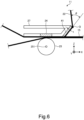
- Fig. 6 is a diagram showing an example of a detailed structure in the periphery of the head frame 27 in the printer apparatus according to the second embodiment.
- the angle of refraction ⁇ is an angle of refraction with respect to the conveying direction for the ink ribbon guided by the side surface in the positive direction on the X-axis.
- the point P is a position spaced apart from the side surface of the head frame 26 by a rubber thickness t of the EPDM rubber sheet 40.
- the point Q is a position spaced apart from the side surface of the head frame 27 by the rubber thickness t of the EPDM rubber sheet 41.
- the ink ribbon 22 When the ink ribbon 22 is backfed, there is a case where the ink ribbon 22 is not uniformly rewound in the region of the wind-up portion R shown in Fig. 5 because of clearances (backlash) provided in portions in which the above-mentioned various gears mesh each other. In such a case, the ink ribbon 22 is loosened in the wind-up portion R. Moreover, when the backfeed is performed in a case where the amount of ink ribbon 22 wound up around the winding reel 23 is larger, the inertia force of the winding reel 23 increases. Therefore, the ink ribbon 22 is more easily loosened as compared to a case where the amount of ink ribbon 22 wound-up is smaller.
Landscapes
- Electronic Switches (AREA)
- Impression-Transfer Materials And Handling Thereof (AREA)
Abstract
Description
- Embodiments described herein generally relate to a printer apparatus.
- Conventionally, for a heat-transfer printer apparatus that performs printing on a print sheet by heating an ink ribbon, a printer apparatus with a torque limiter for cancelling a conveying speed difference between an ink ribbon and a print sheet and winding up the ink ribbon while applying a predetermined tensile force to the ink ribbon has been proposed. In such a printer apparatus, the conveyance of the print sheet and the conveyance of the ink ribbon are performed with a driving force from another driving source.
- However, in order to simplify the structure of the printer apparatus and achieve cost saving and power consumption reduction, the conveyance of the print sheet and the conveyance of the ink ribbon are performed with a driving force from a single driving source. In this case, when the print sheet and the ink ribbon after the printing are fed back to the next print start location, the ink ribbon is sometimes loosened due to the inertia force of a winding reel for the ink ribbon. When the next print is started in a state in which the ink ribbon is loosened, the ink ribbon is suddenly pulled. A large impact is transmitted to a nip region where the print sheet is held in contact with a platen roller. This lowers the print quality at the print start, which is problematic.
- To this end, there is provided a heat-transfer printer apparatus according to
claim 1. Preferred embodiments are set out in the dependent claims. -
-
Fig. 1 is a diagram showing an example of a schematic configuration of a printer apparatus according to a first embodiment. -
Fig. 2 is a first diagram showing an example of a detailed structure in the periphery of a head frame in the printer apparatus according to the first embodiment. -
Fig. 3 is a second diagram showing an example of a detailed structure in the periphery of the head frame in the printer apparatus according to the first embodiment. -
Fig. 4 is a diagram showing an example of a result of assessing a relation between the type of elastic member and the print quality in the printer apparatus according to the first embodiment. -
Fig. 5 is a diagram showing an example of a schematic configuration of a printer apparatus according to a second embodiment. -
Fig. 6 is a diagram showing an example of a detailed structure in the periphery of a head frame in the printer apparatus according to the second embodiment. - In accordance with one embodiment, a heat-transfer printer apparatus includes a single driving source, a print head, a platen roller, a winding reel, a guide member, and an elastic member. The single driving source generates a driving force for conveying a print sheet and an ink ribbon. The printing head performs printing on the print sheet conveyed by the driving force by heating the ink ribbon conveyed by the driving force. The platen roller is provided in opposite to the printing head and conveys the ink ribbon and the print sheet overlapping each other while nipping the ink ribbon and the print sheet between the platen roller and the printing head. The winding reel winds up the ink ribbon after the printing. The guide member guides the ink ribbon and the print sheet nipped by the printing head and the platen roller and guides only the ink ribbon after the printing towards the winding reel. The elastic member is attached to a surface of the guide member, the surface guiding only the ink ribbon towards the winding reel.
- Hereinafter, embodiments will be described in detail with reference to the drawings. In the drawings, the same reference signs denote the same or similar portions. It should be noted that the embodiments are not limited by the following descriptions.
- First of all, a
printer apparatus 10 as a first embodiment will be described. - Referring to
Fig. 1 , a schematic configuration of theprinter apparatus 10 according to the first embodiment will be described.Fig. 1 is a diagram showing an example of a schematic configuration of the printer apparatus according to the first embodiment. - The
printer apparatus 10 is a so-called thermal heat-transfer printer that performs printing on aprint sheet 15 by heating anink ribbon 22. Theprinter apparatus 10 performs printing while pulling out theprint sheet 15 fromroll paper 14, around which theprint sheet 15 is wound in the form of a roll, in the arrow E direction. It should be noted that theroll paper 14 is rotatably supported around ashaft 141 along a Y-axis inFig. 1 . - The
print sheet 15 is, for example, a label sheet or a tag sheet. The label sheet has a structure in which a plurality of same-size labels is arranged at predetermined intervals on a base sheet. The label may have an adhesive layer formed on its back surface and be attached to a base sheet which is release paper so that the label can be released from the base sheet. The tag sheet is, for example, thick paper used as a product price tag or a baggage tag. - The
print sheet 15 pulled out from theroll paper 14 is put on asheet guide 29, changes the direction, and overlaps theink ribbon 22 pulled out in the arrow C direction from aribbon roll 21. Then, theprint sheet 15 is nipped by athermal head 24 and aplaten roller 25 rotating in the arrow B direction. Accordingly, a nip region where thethermal head 24, theink ribbon 22, and theprint sheet 15 are in contact is formed. It should be noted that theribbon roll 21 is rotatably supported around anaxis 211 along the Y-axis inFig. 1 . Moreover, theplaten roller 25 is rotatably supported around ashaft 251 along the Y-axis inFig. 1 . - The
thermal head 24 includes a plurality of heat elements. Thethermal head 24 selectively heats the heat elements, thereby melting ink applied to theink ribbon 22. Then, the molten ink is transferred to theprint sheet 15. In this manner, for example, a desired characters or barcode is printed. - The
thermal head 24 is supported on a surface of ahead frame 26 along the X-axis direction. Thehead frame 26 guides theink ribbon 22 and theprint sheet 15 nipped by thethermal head 24 and theplaten roller 25. Specifically, the surface of thehead frame 26 along the X-axis direction is held in contact with a surface of theink ribbon 22, which is not held in contact with theprint sheet 15, and guides theink ribbon 22 and theprint sheet 15. Thehead frame 26 is an example of a guide member in the present embodiment. - The
print sheet 15 after the printing is completed passes beyond thehead frame 26, and then is guided by a pair ofconveying rollers 16 and delivered from adelivery port 17. Theprint sheet 15 delivered from thedelivery port 17 may be manually cut at the position of thedelivery port 17 or may be cut by a cutter (not shown) placed near thedelivery port 17. - On the other hand, the
ink ribbon 22 after the printing is completed is guided towards awinding reel 23 by a side surface of thehead frame 26 on a positive side on the X-axis. The side surface of thehead frame 26 on the positive side on the X-axis extends in a Z-axis direction. In other words, the side surface on the positive side on the X-axis is a surface in a direction (Z-axis direction) perpendicular to a conveying direction for the ink ribbon guided by the surface along the X-axis direction. Therefore, the conveying direction for theink ribbon 22 is changed upwards by about 90 degrees on the side surface. Thewinding reel 23 rotatably supported around ashaft 231 along the Y-axis inFig. 1 winds up theink ribbon 22 moved away from thehead frame 26 by rotating in the arrow D direction. It should be noted that theink ribbon 22 wound up by thewinding reel 23 is held in contact with a point at which theink ribbon 22 is spaced apart from the side surface of thehead frame 26 irrespective of the amount of theink ribbon 22 wound up by thewinding reel 23. The details will be described later (seeFig. 2 ) . - An ethylene propylene diene monomer (EPDM)
rubber sheet 40 is attached to the side surface of thehead frame 26 on the positive side on the X-axis. TheEPDM rubber sheet 40 is a synthetic rubber obtained by co-polymerizing ethylene and propylene and is molded in the form of a sheet (in the form of a plane). TheEPDM rubber sheet 40 is attached to the side surface of thehead frame 26 with an adhesive or a double sided tape, for example. Therefore, the back side of the ink ribbon 22 (side not held in contact with the print sheet 15) moves to the windingreel 23 via a wind-up portion R shown inFig. 1 while sliding with theEPDM rubber sheet 40. TheEPDM rubber sheet 40 is an example of an elastic member in the present embodiment. It should be noted that theEPDM rubber sheet 40 may be replaced by another elastic member having substantially the same hardness and thickness as theEPDM rubber sheet 40. - It should be noted that a
single driving motor 31 performs the conveyance of theprint sheet 15 and the conveyance of theink ribbon 22. It should be noted that the drivingmotor 31 is an example of a driving source in the present embodiment. - Specifically, when the driving
motor 31 positively rotates, adriving gear 32 directly coupled to anoutput shaft 311 of the drivingmotor 31 rotates in the arrow A direction. The rotation of thedriving gear 32 is transmitted to a platenroller driving gear 34 directly coupled to theshaft 251 of theplaten roller 25 via acoupling gear 33 meshing with thedriving gear 32. - The rotation of the platen
roller driving gear 34 is transmitted to acoupling gear 36 meshing with thecoupling gear 35 via acoupling gear 35 meshing with the platenroller driving gear 34. - A ribbon
roll driving gear 37 and a windingreel driving gear 38 mesh with thecoupling gear 36. Therefore, along with rotation of theplaten roller 25 in the arrow B direction, theribbon roll 21 rotates in the arrow C direction and the windingreel 23 rotates in the arrow D direction. - The platen
roller driving gear 34 rotates theplaten roller 25 in the arrow B direction. Then, with the rotation of theplaten roller 25, the printing is performed while theprint sheet 15 and theink ribbon 22 nipped by theplaten roller 25 and thethermal head 24 are conveyed in a positive direction on the X-axis. It should be noted that the diameter and the number of teeth for each gear are set so that the conveying speed for theink ribbon 22 is equal to or higher than that for theplaten roller 25 in order not to loosen theink ribbon 22 when the printing is performed. - When the printing on the
print sheet 15 is completed, theprint sheet 15 is further conveyed (fed) in the positive direction on the X-axis and delivered from thedelivery port 17. Moreover, theink ribbon 22 is wound up by the windingreel 23. - The printed
print sheet 15 delivered from thedelivery port 17 is cut, and then theprinter apparatus 10 performs backfeed for returning theprint sheet 15 to the next print start location. At this time, the drivingmotor 31 rotates in a direction opposite to the direction when performing the printing. That is, thedriving gear 32 rotates in a direction opposite to the arrow A. - By the rotation of the
driving gear 32 being transmitted to the respective gears described above, theplaten roller 25, theribbon roll 21, and the windingreel 23 all rotate in the direction opposite to the direction when performing the printing. Accordingly, theprint sheet 15 and theink ribbon 22 are conveyed in a negative direction on the X-axis. - In order to determine a suitable print timing, the
printer apparatus 10 includes a labelgap detection sensor 28 and a tagsheet detection sensor 30 for detecting the position of theprint sheet 15. - The label
gap detection sensor 28 is a transmissive optical sensor. In a case where a label sheet is used as theprint sheet 15, the labelgap detection sensor 28 detects a timing mark shown at a label gap position on the back side on a print surface of the label sheet. - The tag
sheet detection sensor 30 is a reflective optical sensor. In a case where a tag sheet is used as theprint sheet 15, the tagsheet detection sensor 30 detects a timing mark shown at the back of a print surface of the tag sheet. - Those sensors operate in accordance with the type of
print sheet 15, which is set before the print start. - Next, behaviors of the
ink ribbon 22 when theprinter apparatus 10 performs backfeed will be described with reference toFigs. 2 and3 .Fig. 2 is a first diagram showing an example of a detailed structure in the periphery of thehead frame 26 in theprinter apparatus 10 according to the first embodiment.Fig. 3 is a second diagram showing an example of a detailed structure in the periphery of thehead frame 26 in theprinter apparatus 10 according to the first embodiment. - First of all, referring to
Fig. 2 , the wind-up path for theink ribbon 22 will be described in more detail. Theink ribbon 22 after the printing is conveyed in the positive direction on the X-axis along thehead frame 26, changes the direction upwards by substantially 90 degrees, and is conveyed in a positive direction on the Z-axis along theEPDM rubber sheet 40. At that time, theink ribbon 22 is conveyed while sliding on the surface of theEPDM rubber sheet 40. Then, theink ribbon 22 changes the direction by an angle of refraction θ at a point P and moves towards the winding reel 23 (seeFig. 1 ). The angle of refraction θ is an angle of refraction with respect to the conveying direction for the ink ribbon guided by the side surface in the positive direction on the X-axis. The point P is a position spaced apart from the side surface of thehead frame 26 by a rubber thickness t of theEPDM rubber sheet 40. Although the angle of refraction θ depends on the amount of theink ribbon 22 wound up by the windingreel 23, a positional relation between theshaft 231 of the windingreel 23 and thehead frame 26 is set so that θ > 0 degrees is constantly established irrespective of the amount of theink ribbon 22 wound up by the windingreel 23. Therefore, theink ribbon 22 is constantly pushed against the point P. - When the
ink ribbon 22 is backfed, there is a case where theink ribbon 22 is not uniformly rewound in the region of the wind-up portion R shown inFig. 1 because of clearances (backlash) provided in portions where the above-mentioned various gears mesh each other. In such a case, theink ribbon 22 is loosened in the wind-up portion R. In particular, when the backfeed is performed in a case where the amount ofink ribbon 22 wound up around the windingreel 23 is larger, theink ribbon 22 is more easily loosened because the inertia force of the windingreel 23 increases as compared to a case where the amount ofink ribbon 22 wound-up is smaller. - If the next print is started in a state in which the
ink ribbon 22 is loosened in the wind-up portion R in this manner, the loosenedink ribbon 22 is suddenly pulled, and a large impact is transmitted to the nip region where thethermal head 24, theink ribbon 22, and theprint sheet 15 are in contact. Therefore, blurry printing, faint printing, etc. may occur at the print start, which lowers the print quality. - With the
EPDM rubber sheet 40 attached to thehead frame 26 in theprinter apparatus 10 according to the present embodiment, an impact generated when the loosenedink ribbon 22 is suddenly pulled at the print start is absorbed by an elastic force of theEPDM rubber sheet 40. Since this can reduce the impact transmitted to the nip region, lowering of the print quality can be prevented. - As shown in
Fig. 3 , a width Wa of theEPDM rubber sheet 40 in a direction orthogonal to the conveying direction for theink ribbon 22 is set to be larger than a width Wb of theink ribbon 22. In other words, both end portions of theEPDM rubber sheet 40 project from both end portions of theink ribbon 22 in the width direction. Accordingly, the entire surface of theink ribbon 22 is held in contact with theEPDM rubber sheet 40 on the side surface of thehead frame 26. - With such a configuration, the
ink ribbon 22 can be slid in a state in which the back surface of theink ribbon 22 is reliably held in contact with theEPDM rubber sheet 40 even if theink ribbon 22 is meandering. - Referring to
Fig. 4 , suitable design conditions for theEPDM rubber sheet 40 will be described.Fig. 4 is a diagram showing an example of a result of assessing a relation between the type of elastic member and the print quality. - Primary design parameters for the
EPDM rubber sheet 40 used in theprinter apparatus 10 according to the present embodiment are rubber hardness H and the rubber thickness t. - The rubber hardness H is measured by pushing a measurement tool called durometer against a test sample and measuring how far an indenter travels in the test sample with a constant force applied on the indenter. The measurement result is expressed by degrees. The smaller the degrees are, the softer the test sample is. For example, hardness 100 degrees indicates hardness like a glass and a general rubber hardness ranges from approximately 40 degrees to 70 degrees.
- The rubber thickness t is the thickness of the
EPDM rubber sheet 40. - The inventor of the present embodiment assessed the print quality of the
printer apparatus 10 by using a plurality ofEPDM rubber sheets 40 different in the rubber hardness H and the rubber thickness t. Moreover, the inventor compared it with the print quality with noEPDM rubber sheet 40.Fig. 4 shows an example of assessment results. - As results of assessment, the inventor has found that it is desirable that the rubber hardness H of the
EPDM rubber sheet 40 ranges from 45 degrees to 65 degrees. - The inventor has found that in a case where the rubber hardness H is lower (softer) than 45 degrees, silicon applied to the back of the
ink ribbon 22 in order to improve its sliding ability sticks to the surface of theEPDM rubber sheet 40. Further, the inventor has found that the silicon sticking to the surface of theEPDM rubber sheet 40 makes theEPDM rubber sheet 40 slipperier, which reduces the impact absorbing effect when theink ribbon 22 is suddenly pulled, applying a high tensile force, and leads to lowering of the print quality. - On the other hand, the inventor has found that in a case where the rubber hardness H is higher (harder) than 65 degrees, it reduces the impact absorbing effect when the
ink ribbon 22 is suddenly pulled, applying a high tensile force, and leads to lowering of the print quality. - Moreover, as results of assessment, the inventor has found that it is desirable that the rubber thickness t of the
EPDM rubber sheet 40 range from 0.5 mm to 2.0 mm. - Since a too small rubber thickness t lowers the durability, it is desirable that the thickness be at least equal to or larger than 0.5 mm. On the other hand, if the rubber thickness t of the
EPDM rubber sheet 40 is larger than 2.0 mm, theink ribbon 22 largely deflects theEPDM rubber sheet 40 when a tensile force is applied to theink ribbon 22 in a region where the rubber hardness H of theEPDM rubber sheet 40 is smaller (softer). Then, theink ribbon 22 held in contact with thethermal head 24 is pulled, which leads to lowering of the print quality. Moreover, the inventor has found that regarding a region where the rubber thickness t is equal to or larger than 2.0 mm, it is a combined region where a relation between the rubber thickness t and the hardness of theEPDM rubber sheet 40 is unstable, so the rubber thickness t is desirably equal to or smaller than 2.0 mm. - As described above, the
printer apparatus 10 according to the embodiment is a heat-transfer printer apparatus with the thermal head 24 (printing head) that performs printing on theprint sheet 15 by heating theink ribbon 22, including the single driving motor 31 (driving source), the head frame 26 (guide member), and the EPDM rubber sheet 40 (elastic member). Thesingle driving motor 31 generates a driving force for conveying theprint sheet 15 and theink ribbon 22. Moreover, thehead frame 26 supports thethermal head 24 and guides theink ribbon 22 and theprint sheet 15 nipped by thethermal head 24 and theplaten roller 25 and guides theink ribbon 22 after the printing towards the windingreel 23. Moreover, theEPDM rubber sheet 40 is a sheet-like member attached to a surface of the side surfaces of thehead frame 26, which are held in contact with theink ribbon 22, the surface guiding theink ribbon 22 after the printing towards the windingreel 23. Therefore, theEPDM rubber sheet 40 absorbs the impact when theink ribbon 22 is suddenly pulled at the print start. Therefore, lowering of the print quality due to theink ribbon 22 loosened during the backfeed can be prevented with a simple structure. - Moreover, in the
printer apparatus 10 according to the embodiment, the width Wa of the EPDM rubber sheet 40 (elastic member) in the direction orthogonal to the conveying direction for theink ribbon 22 is larger than the width Wb of theink ribbon 22. Therefore, theink ribbon 22 can be slid in a state in which the back surface of theink ribbon 22 is reliably held in contact with theEPDM rubber sheet 40 even if theink ribbon 22 is meandering. - Moreover, in the
printer apparatus 10 according to the embodiment, the rubber hardness H of the EPDM rubber sheet 40 (elastic member) ranges from 45 degrees to 60 degrees, and the rubber thickness t of the EPDM rubber sheet 40 (elastic member) ranges from 0.5 mm to 2.0 mm. Therefore, lowering of the print quality due to theink ribbon 22 loosened during the backfeed can be prevented. - Moreover, in the
printer apparatus 10 according to the embodiment, the elastic member is theEPDM rubber sheet 40. Therefore, since theEPDM rubber sheet 40 absorbs the impact when theink ribbon 22 is suddenly pulled at the print start. Thus, lowering of the print quality due to theink ribbon 22 loosened during the backfeed can be prevented with a simple structure. - Next, a
printer apparatus 11 as a second embodiment will be described. -
Fig. 5 is a diagram showing an example of a schematic configuration of the printer apparatus according to the second embodiment. Theprinter apparatus 11 shown inFig. 5 includes ahead frame 27 instead of thehead frame 26 of theprinter apparatus 10 described above in the first embodiment. It should be noted that operations of the respective parts of theprinter apparatus 11 are similar to those of theprinter apparatus 10 described above, so duplicate descriptions will be omitted and only differences from theprinter apparatus 10 will be described below. - The
head frame 27 keeps thethermal head 24 in contact with theplaten roller 25. Thehead frame 27 is an example of the guide member in the present embodiment. - The
ink ribbon 22 after the printing is completed is guided by a side surface of thehead frame 27 on a positive side on the X-axis and moves towards the windingreel 23. The side surface on the positive side on the X-axis is a surface tilting in a conveying direction for theink ribbon 22 from a surface in a direction (Z-axis direction) perpendicular to a conveying direction for the ink ribbon conveyed while being guided by the surface along the X-axis direction. On the side surface on the positive side on the X-axis, the conveying direction for theink ribbon 22 is changed to obliquely upper right inFig. 5 . The windingreel 23 rotatably supported around ashaft 231 along the Y-axis inFig. 5 winds up theink ribbon 22 moved away from thehead frame 27 by rotating in the arrow D direction. It should be noted that theink ribbon 22 wound up by the windingreel 23 is held in contact with a point at which theink ribbon 22 is spaced apart from the side surface of thehead frame 27 irrespective of the amount of theink ribbon 22 wound up by the windingreel 23. The details will be described later (seeFig. 6 ) . - An
EPDM rubber sheet 41 is attached to the side surface of thehead frame 27 on the positive side on the X-axis. TheEPDM rubber sheet 41 is molded in the form of a sheet (in the form of a plane). TheEPDM rubber sheet 41 is attached to the side surface of thehead frame 27 with an adhesive, for example. Therefore, the back side of the ink ribbon 22 (side not held in contact with the print sheet 15) moves towards the windingreel 23 via a wind-up portion R shown inFig. 5 while sliding with theEPDM rubber sheet 41. TheEPDM rubber sheet 41 is an example of the elastic member in the present embodiment. - Which direction the side surface of the
head frame 26 in the first embodiment or the side surface of thehead frame 27 in the second embodiment is oriented only needs to be determined depending on the positional relation between the head frame and the windingreel 23 in the printer apparatus. That is, as to the direction of the side surface of the head frame, it is sufficient to form it in such a direction that theink ribbon 22 wound up by the windingreel 23 is constantly held in contact with the point spaced apart from the side surface of the head frame irrespective of the amount of theink ribbon 22 wound up by the windingreel 23. - Next, behaviors of the
ink ribbon 22 when theprinter apparatus 11 performs backfeed will be described with reference toFig. 6. Fig. 6 is a diagram showing an example of a detailed structure in the periphery of thehead frame 27 in the printer apparatus according to the second embodiment. - Referring to
Fig. 6 , the wind-up path for theink ribbon 22 will be described in more detail. Theink ribbon 22 after the printing is conveyed in the positive direction on the X-axis along thehead frame 26, changes the direction to obliquely upper right inFig. 6 , and is conveyed in a positive direction on the Z-axis along theEPDM rubber sheet 41. At that time, theink ribbon 22 is conveyed while sliding on the surface of theEPDM rubber sheet 41. Then, theink ribbon 22 changes the direction by an angle of refraction θ at a point Q and moves towards the winding reel 23 (seeFig. 5 ). The angle of refraction θ is an angle of refraction with respect to the conveying direction for the ink ribbon guided by the side surface in the positive direction on the X-axis. The point P is a position spaced apart from the side surface of thehead frame 26 by a rubber thickness t of theEPDM rubber sheet 40. The point Q is a position spaced apart from the side surface of thehead frame 27 by the rubber thickness t of theEPDM rubber sheet 41. Although the angle of refraction θ depends on the amount of theink ribbon 22 wound up by the windingreel 23, a positional relation between theshaft 231 of the windingreel 23 and thehead frame 27 is set so that θ > 0 degrees is constantly established irrespective of the amount of theink ribbon 22 wound up by the windingreel 23. Therefore, theink ribbon 22 is constantly pushed against the point Q. - When the
ink ribbon 22 is backfed, there is a case where theink ribbon 22 is not uniformly rewound in the region of the wind-up portion R shown inFig. 5 because of clearances (backlash) provided in portions in which the above-mentioned various gears mesh each other. In such a case, theink ribbon 22 is loosened in the wind-up portion R. Moreover, when the backfeed is performed in a case where the amount ofink ribbon 22 wound up around the windingreel 23 is larger, the inertia force of the windingreel 23 increases. Therefore, theink ribbon 22 is more easily loosened as compared to a case where the amount ofink ribbon 22 wound-up is smaller. - If the next print is started in a state in which the
ink ribbon 22 is loosened in the wind-up portion R in this manner, the loosenedink ribbon 22 is suddenly pulled. Therefore, a large impact is transmitted to the nip region where thethermal head 24, theink ribbon 22, and theprint sheet 15 are in contact. Accordingly, blurry printing, faint printing, etc. may occur, which lowers the print quality. - As described above, with the
EPDM rubber sheet 41 attached to thehead frame 27 in theprinter apparatus 11 according to the present embodiment, an impact generated when the loosenedink ribbon 22 is suddenly pulled at the print start is absorbed by an elastic force of theEPDM rubber sheet 41. Since this can reduce the impact transmitted to the nip region, lowering of the print quality can be prevented. - While certain embodiments have been described, these embodiments have been presented by way of example only, and are not intended to limit the scope of the inventions. Indeed, the novel embodiments described herein may be embodied in a variety of other forms; furthermore, various omissions, substitutions and changes in the form of the embodiments described herein may be made without departing from the scope of the inventions. The accompanying claims are intended to cover such forms or modifications as would fall within the scope of the inventions.
Claims (15)
- A heat-transfer printer apparatus, comprising:a single driving source (31) that generates a driving force for conveying a print sheet and an ink ribbon;a printing head (24) that performs printing on the print sheet conveyed by the driving force by heating the ink ribbon conveyed by the driving force;a platen roller (25) that is provided in opposite to the printing head and conveys the ink ribbon and the print sheet overlapping each other while nipping the ink ribbon and the print sheet between the platen roller and the printing head;a winding reel (23) that winds up the ink ribbon after the printing;a guide member (26, 27) that guides the ink ribbon and the print sheet nipped by the printing head and the platen roller and guides only the ink ribbon after the printing towards the winding reel; anda sheet-like elastic member (40, 41) attached to a surface of the guide member, the surface guiding only the ink ribbon towards the winding reel.
- The heat-transfer printer apparatus according to claim 1, whereinthe guide member hasa first surface that guides the ink ribbon and the print sheet overlapping each other anda second surface that guides only the ink ribbon after the printing towards the winding reel, andthe elastic member is attached to the second surface.
- The heat-transfer printer apparatus according to claim 2, wherein
the guide member supports the printing head in the first surface. - The heat-transfer printer apparatus according to claim 2, whereinthe first surface becomes into contact with a surface of the ink ribbon, the surface being not in contact with the print sheet,the elastic member attached to the second surface becomes into contact with the surface of the ink ribbon after the printing, the surface being not in contact with the print sheet, andthe ink ribbon is guided towards the winding reel while the surface not in contact with the print sheet sliding with the elastic member.
- The heat-transfer printer apparatus according to claim 2, wherein
the second surface is a surface perpendicular to a conveying direction for the ink ribbon conveyed while being guided by the first surface. - The heat-transfer printer apparatus according to claim 2, wherein
the second surface is a surface tilting from a surface perpendicular to a conveying direction for the ink ribbon conveyed while being guided by the first surface, in the conveying direction. - The heat-transfer printer apparatus according to claim 2, wherein
the winding reel is configured to wind up the ink ribbon after passing beyond the second surface in such a direction that an angle of refraction with respect to a conveying direction for the ink ribbon guided by the second surface is larger than 0 degrees. - The heat-transfer printer apparatus according to claim 7, wherein
the winding reel is configured to wind up the ink ribbon after passing beyond the second surface in such a way that the ink ribbon changes the direction by the angle of refraction at a point which is spaced apart from the second surface of the guide member by a thickness of the elastic member. - The heat-transfer printer apparatus according to claim 8, wherein the winding reel is configured to wind up the ink ribbon after passing beyond the second surface in such a way that the ink ribbon is constantly pushed against the point.
- The heat-transfer printer apparatus according to any one of claims 1 to 9, wherein the elastic member is configured to become into contact with the entire surface of the ink ribbon.
- The heat-transfer printer apparatus according to any one of claims 1 to 10, wherein
a width of the elastic member in a direction orthogonal to a conveying direction for the ink ribbon is larger than a width of the ink ribbon in a direction orthogonal to the conveying direction. - The heat-transfer printer apparatus according to any one of claims 1 to 11, wherein
the elastic member has rubber hardness of from 45 degrees to 60 degrees. - The heat-transfer printer apparatus according to any one of claims 1 to 12, wherein
the elastic member has a thickness of from 0.5 mm to 2.0 mm. - The heat-transfer printer apparatus according to any one of claims 1 to 13, wherein
the elastic member is a sheet-like member including ethylene propylene rubber. - The heat-transfer printer apparatus according to any one of claims 1 to 14, further comprising a detection sensor (28, 30) .
Applications Claiming Priority (1)
| Application Number | Priority Date | Filing Date | Title |
|---|---|---|---|
| JP2023071032A JP7834685B2 (en) | 2023-04-24 | 2023-04-24 | Printer device |
Publications (2)
| Publication Number | Publication Date |
|---|---|
| EP4454890A1 true EP4454890A1 (en) | 2024-10-30 |
| EP4454890B1 EP4454890B1 (en) | 2026-05-20 |
Family
ID=89767060
Family Applications (1)
| Application Number | Title | Priority Date | Filing Date |
|---|---|---|---|
| EP24154218.2A Active EP4454890B1 (en) | 2023-04-24 | 2024-01-26 | PRINTER |
Country Status (4)
| Country | Link |
|---|---|
| US (1) | US12600154B2 (en) |
| EP (1) | EP4454890B1 (en) |
| JP (1) | JP7834685B2 (en) |
| CN (1) | CN118832965A (en) |
Citations (3)
| Publication number | Priority date | Publication date | Assignee | Title |
|---|---|---|---|---|
| US6157399A (en) * | 1994-02-22 | 2000-12-05 | Matsushita Electric Industrial Co., Ltd. | Color image recording apparatus |
| US20050195269A1 (en) * | 2004-01-26 | 2005-09-08 | Alps Electric Co., Ltd. | Heat transfer printer |
| US10647139B1 (en) * | 2019-02-01 | 2020-05-12 | Toshiba Tec Kabushiki Kaisha | Printer and ribbon winding features |
Family Cites Families (14)
| Publication number | Priority date | Publication date | Assignee | Title |
|---|---|---|---|---|
| JPS61215074A (en) * | 1985-03-20 | 1986-09-24 | Hitachi Ltd | Thermal transfer printer or thermal printer |
| JPS63132742U (en) * | 1987-02-23 | 1988-08-30 | ||
| JP2556346B2 (en) * | 1987-12-04 | 1996-11-20 | キヤノン株式会社 | Ink ribbon cassette |
| JPH0634958U (en) * | 1992-10-16 | 1994-05-10 | アルプス電気株式会社 | Ink ribbon cassette for thermal transfer printer |
| JPH06336076A (en) * | 1993-05-27 | 1994-12-06 | Tokyo Electric Co Ltd | Transfer printer |
| JPH0789171A (en) | 1993-09-22 | 1995-04-04 | Sony Corp | Printer |
| JPH07101089A (en) * | 1993-10-07 | 1995-04-18 | Graphtec Corp | Thermal transfer recorder |
| JPH07227981A (en) * | 1994-02-22 | 1995-08-29 | Matsushita Electric Ind Co Ltd | Thermal transfer recorder |
| JPH09267499A (en) * | 1996-04-01 | 1997-10-14 | Matsushita Electric Ind Co Ltd | Video printer |
| JPH1148562A (en) * | 1997-08-01 | 1999-02-23 | Fuji Photo Film Co Ltd | Ink ribbon peeling mechanism of thermal transfer device |
| JP2000062270A (en) | 1998-08-24 | 2000-02-29 | Sharp Corp | Thermal transfer recording device |
| JP2001063868A (en) | 1999-08-31 | 2001-03-13 | Matsushita Electric Ind Co Ltd | Thermal transfer recording device |
| US6585437B1 (en) * | 1999-09-27 | 2003-07-01 | Intermec Ip Corp. | Method and apparatus for reliable printing on linerless label stock |
| JP2006015656A (en) * | 2004-07-02 | 2006-01-19 | Alps Electric Co Ltd | Thermal transfer line printer |
-
2023
- 2023-04-24 JP JP2023071032A patent/JP7834685B2/en active Active
-
2024
- 2024-01-18 US US18/416,282 patent/US12600154B2/en active Active
- 2024-01-26 EP EP24154218.2A patent/EP4454890B1/en active Active
- 2024-03-15 CN CN202410299513.0A patent/CN118832965A/en active Pending
Patent Citations (3)
| Publication number | Priority date | Publication date | Assignee | Title |
|---|---|---|---|---|
| US6157399A (en) * | 1994-02-22 | 2000-12-05 | Matsushita Electric Industrial Co., Ltd. | Color image recording apparatus |
| US20050195269A1 (en) * | 2004-01-26 | 2005-09-08 | Alps Electric Co., Ltd. | Heat transfer printer |
| US10647139B1 (en) * | 2019-02-01 | 2020-05-12 | Toshiba Tec Kabushiki Kaisha | Printer and ribbon winding features |
Also Published As
| Publication number | Publication date |
|---|---|
| US12600154B2 (en) | 2026-04-14 |
| EP4454890B1 (en) | 2026-05-20 |
| JP2024156510A (en) | 2024-11-06 |
| US20240351358A1 (en) | 2024-10-24 |
| CN118832965A (en) | 2024-10-25 |
| JP7834685B2 (en) | 2026-03-24 |
Similar Documents
| Publication | Publication Date | Title |
|---|---|---|
| US7249903B2 (en) | Assembly for feeding a continuous roll of web material to a sheet fed printing device | |
| JP6201516B2 (en) | Image forming apparatus | |
| WO2012077709A1 (en) | Printer | |
| EP2689934A1 (en) | Image forming apparatus and image forming method | |
| CN110126489B (en) | Printer, control method, computer-readable storage medium, and electronic device | |
| JP6176016B2 (en) | Image forming apparatus | |
| JP2019005971A (en) | Printer and program | |
| US4948282A (en) | Drive device for a thermal transfer printer | |
| US12600154B2 (en) | Printer apparatus | |
| JP2010201631A (en) | Printer | |
| JP7465774B2 (en) | Printer device | |
| JPH09263348A (en) | Roll paper feeder | |
| US6860201B2 (en) | Printing apparatus | |
| JP4619693B2 (en) | Passbook printing apparatus and printing method | |
| WO2015151367A1 (en) | Device and method for determining whether liner-free label has gotten caught in thermal printer | |
| US12485678B2 (en) | Printer | |
| US12420577B2 (en) | Printer | |
| JP2013049281A (en) | Thermal printer | |
| JP2001072292A (en) | Roll sheet feeding device and sheet processing device | |
| JP2007301868A (en) | Printer | |
| JP2016030653A (en) | Winder | |
| JP2012171293A (en) | Thermal transfer printer | |
| JP5850455B2 (en) | Printing device | |
| JP2003103813A (en) | Thermal transfer printer | |
| JP4661537B2 (en) | Sheet conveying apparatus and image forming apparatus |
Legal Events
| Date | Code | Title | Description |
|---|---|---|---|
| PUAI | Public reference made under article 153(3) epc to a published international application that has entered the european phase |
Free format text: ORIGINAL CODE: 0009012 |
|
| STAA | Information on the status of an ep patent application or granted ep patent |
Free format text: STATUS: THE APPLICATION HAS BEEN PUBLISHED |
|
| AK | Designated contracting states |
Kind code of ref document: A1 Designated state(s): AL AT BE BG CH CY CZ DE DK EE ES FI FR GB GR HR HU IE IS IT LI LT LU LV MC ME MK MT NL NO PL PT RO RS SE SI SK SM TR |
|
| STAA | Information on the status of an ep patent application or granted ep patent |
Free format text: STATUS: REQUEST FOR EXAMINATION WAS MADE |
|
| 17P | Request for examination filed |
Effective date: 20250430 |
|
| GRAJ | Information related to disapproval of communication of intention to grant by the applicant or resumption of examination proceedings by the epo deleted |
Free format text: ORIGINAL CODE: EPIDOSDIGR1 |
|
| GRAP | Despatch of communication of intention to grant a patent |
Free format text: ORIGINAL CODE: EPIDOSNIGR1 |
|
| GRAP | Despatch of communication of intention to grant a patent |
Free format text: ORIGINAL CODE: EPIDOSNIGR1 |
|
| STAA | Information on the status of an ep patent application or granted ep patent |
Free format text: STATUS: GRANT OF PATENT IS INTENDED |
|
| INTG | Intention to grant announced |
Effective date: 20251218 |
|
| GRAS | Grant fee paid |
Free format text: ORIGINAL CODE: EPIDOSNIGR3 |
|
| GRAA | (expected) grant |
Free format text: ORIGINAL CODE: 0009210 |
|
| STAA | Information on the status of an ep patent application or granted ep patent |
Free format text: STATUS: THE PATENT HAS BEEN GRANTED |
|
| AK | Designated contracting states |
Kind code of ref document: B1 Designated state(s): AL AT BE BG CH CY CZ DE DK EE ES FI FR GB GR HR HU IE IS IT LI LT LU LV MC ME MK MT NL NO PL PT RO RS SE SI SK SM TR |
|
| REG | Reference to a national code |
Ref country code: CH Ref legal event code: F10 Free format text: ST27 STATUS EVENT CODE: U-0-0-F10-F00 (AS PROVIDED BY THE NATIONAL OFFICE) Effective date: 20260520 Ref country code: GB Ref legal event code: FG4D |
|
| REG | Reference to a national code |
Ref country code: DE Ref legal event code: R096 Ref document number: 602024004870 Country of ref document: DE |