EP4454880A1 - Ceramic matrix composite (cmc) component resistant to edge cracks - Google Patents
Ceramic matrix composite (cmc) component resistant to edge cracks Download PDFInfo
- Publication number
- EP4454880A1 EP4454880A1 EP24168522.1A EP24168522A EP4454880A1 EP 4454880 A1 EP4454880 A1 EP 4454880A1 EP 24168522 A EP24168522 A EP 24168522A EP 4454880 A1 EP4454880 A1 EP 4454880A1
- Authority
- EP
- European Patent Office
- Prior art keywords
- cmc
- ply
- end cap
- edge
- laminate structure
- Prior art date
- Legal status (The legal status is an assumption and is not a legal conclusion. Google has not performed a legal analysis and makes no representation as to the accuracy of the status listed.)
- Pending
Links
- 239000011153 ceramic matrix composite Substances 0.000 title claims abstract description 240
- 239000000835 fiber Substances 0.000 claims abstract description 67
- 239000000463 material Substances 0.000 claims abstract description 43
- 239000002657 fibrous material Substances 0.000 claims abstract description 38
- 238000000034 method Methods 0.000 claims description 46
- 239000011159 matrix material Substances 0.000 claims description 14
- 229920002134 Carboxymethyl cellulose Polymers 0.000 description 3
- 235000010948 carboxy methyl cellulose Nutrition 0.000 description 3
- 229920006184 cellulose methylcellulose Polymers 0.000 description 3
- 238000012710 chemistry, manufacturing and control Methods 0.000 description 3
- 238000010276 construction Methods 0.000 description 3
- 239000000919 ceramic Substances 0.000 description 2
- 238000002485 combustion reaction Methods 0.000 description 2
- 238000005056 compaction Methods 0.000 description 2
- 238000010586 diagram Methods 0.000 description 2
- 238000000626 liquid-phase infiltration Methods 0.000 description 2
- 238000012986 modification Methods 0.000 description 2
- 230000004048 modification Effects 0.000 description 2
- 238000003825 pressing Methods 0.000 description 2
- HBMJWWWQQXIZIP-UHFFFAOYSA-N silicon carbide Chemical compound [Si+]#[C-] HBMJWWWQQXIZIP-UHFFFAOYSA-N 0.000 description 2
- PZNSFCLAULLKQX-UHFFFAOYSA-N Boron nitride Chemical compound N#B PZNSFCLAULLKQX-UHFFFAOYSA-N 0.000 description 1
- 230000006835 compression Effects 0.000 description 1
- 238000007906 compression Methods 0.000 description 1
- 230000002401 inhibitory effect Effects 0.000 description 1
- 238000003475 lamination Methods 0.000 description 1
- 230000000704 physical effect Effects 0.000 description 1
Images




Classifications
-
- C—CHEMISTRY; METALLURGY
- C04—CEMENTS; CONCRETE; ARTIFICIAL STONE; CERAMICS; REFRACTORIES
- C04B—LIME, MAGNESIA; SLAG; CEMENTS; COMPOSITIONS THEREOF, e.g. MORTARS, CONCRETE OR LIKE BUILDING MATERIALS; ARTIFICIAL STONE; CERAMICS; REFRACTORIES; TREATMENT OF NATURAL STONE
- C04B35/00—Shaped ceramic products characterised by their composition; Ceramics compositions; Processing powders of inorganic compounds preparatory to the manufacturing of ceramic products
- C04B35/71—Ceramic products containing macroscopic reinforcing agents
- C04B35/78—Ceramic products containing macroscopic reinforcing agents containing non-metallic materials
- C04B35/80—Fibres, filaments, whiskers, platelets, or the like
-
- B—PERFORMING OPERATIONS; TRANSPORTING
- B32—LAYERED PRODUCTS
- B32B—LAYERED PRODUCTS, i.e. PRODUCTS BUILT-UP OF STRATA OF FLAT OR NON-FLAT, e.g. CELLULAR OR HONEYCOMB, FORM
- B32B18/00—Layered products essentially comprising ceramics, e.g. refractory products
-
- B—PERFORMING OPERATIONS; TRANSPORTING
- B32—LAYERED PRODUCTS
- B32B—LAYERED PRODUCTS, i.e. PRODUCTS BUILT-UP OF STRATA OF FLAT OR NON-FLAT, e.g. CELLULAR OR HONEYCOMB, FORM
- B32B5/00—Layered products characterised by the non- homogeneity or physical structure, i.e. comprising a fibrous, filamentary, particulate or foam layer; Layered products characterised by having a layer differing constitutionally or physically in different parts
- B32B5/02—Layered products characterised by the non- homogeneity or physical structure, i.e. comprising a fibrous, filamentary, particulate or foam layer; Layered products characterised by having a layer differing constitutionally or physically in different parts characterised by structural features of a fibrous or filamentary layer
- B32B5/12—Layered products characterised by the non- homogeneity or physical structure, i.e. comprising a fibrous, filamentary, particulate or foam layer; Layered products characterised by having a layer differing constitutionally or physically in different parts characterised by structural features of a fibrous or filamentary layer characterised by the relative arrangement of fibres or filaments of different layers, e.g. the fibres or filaments being parallel or perpendicular to each other
-
- F—MECHANICAL ENGINEERING; LIGHTING; HEATING; WEAPONS; BLASTING
- F02—COMBUSTION ENGINES; HOT-GAS OR COMBUSTION-PRODUCT ENGINE PLANTS
- F02C—GAS-TURBINE PLANTS; AIR INTAKES FOR JET-PROPULSION PLANTS; CONTROLLING FUEL SUPPLY IN AIR-BREATHING JET-PROPULSION PLANTS
- F02C7/00—Features, components parts, details or accessories, not provided for in, or of interest apart form groups F02C1/00 - F02C6/00; Air intakes for jet-propulsion plants
-
- B—PERFORMING OPERATIONS; TRANSPORTING
- B32—LAYERED PRODUCTS
- B32B—LAYERED PRODUCTS, i.e. PRODUCTS BUILT-UP OF STRATA OF FLAT OR NON-FLAT, e.g. CELLULAR OR HONEYCOMB, FORM
- B32B2250/00—Layers arrangement
- B32B2250/42—Alternating layers, e.g. ABAB(C), AABBAABB(C)
-
- B—PERFORMING OPERATIONS; TRANSPORTING
- B32—LAYERED PRODUCTS
- B32B—LAYERED PRODUCTS, i.e. PRODUCTS BUILT-UP OF STRATA OF FLAT OR NON-FLAT, e.g. CELLULAR OR HONEYCOMB, FORM
- B32B2307/00—Properties of the layers or laminate
- B32B2307/50—Properties of the layers or laminate having particular mechanical properties
-
- B—PERFORMING OPERATIONS; TRANSPORTING
- B32—LAYERED PRODUCTS
- B32B—LAYERED PRODUCTS, i.e. PRODUCTS BUILT-UP OF STRATA OF FLAT OR NON-FLAT, e.g. CELLULAR OR HONEYCOMB, FORM
- B32B2307/00—Properties of the layers or laminate
- B32B2307/50—Properties of the layers or laminate having particular mechanical properties
- B32B2307/552—Fatigue strength
-
- B—PERFORMING OPERATIONS; TRANSPORTING
- B32—LAYERED PRODUCTS
- B32B—LAYERED PRODUCTS, i.e. PRODUCTS BUILT-UP OF STRATA OF FLAT OR NON-FLAT, e.g. CELLULAR OR HONEYCOMB, FORM
- B32B2603/00—Vanes, blades, propellers, rotors with blades
-
- C—CHEMISTRY; METALLURGY
- C04—CEMENTS; CONCRETE; ARTIFICIAL STONE; CERAMICS; REFRACTORIES
- C04B—LIME, MAGNESIA; SLAG; CEMENTS; COMPOSITIONS THEREOF, e.g. MORTARS, CONCRETE OR LIKE BUILDING MATERIALS; ARTIFICIAL STONE; CERAMICS; REFRACTORIES; TREATMENT OF NATURAL STONE
- C04B2235/00—Aspects relating to ceramic starting mixtures or sintered ceramic products
- C04B2235/02—Composition of constituents of the starting material or of secondary phases of the final product
- C04B2235/50—Constituents or additives of the starting mixture chosen for their shape or used because of their shape or their physical appearance
- C04B2235/52—Constituents or additives characterised by their shapes
- C04B2235/5208—Fibers
- C04B2235/5252—Fibers having a specific pre-form
-
- C—CHEMISTRY; METALLURGY
- C04—CEMENTS; CONCRETE; ARTIFICIAL STONE; CERAMICS; REFRACTORIES
- C04B—LIME, MAGNESIA; SLAG; CEMENTS; COMPOSITIONS THEREOF, e.g. MORTARS, CONCRETE OR LIKE BUILDING MATERIALS; ARTIFICIAL STONE; CERAMICS; REFRACTORIES; TREATMENT OF NATURAL STONE
- C04B2237/00—Aspects relating to ceramic laminates or to joining of ceramic articles with other articles by heating
- C04B2237/30—Composition of layers of ceramic laminates or of ceramic or metallic articles to be joined by heating, e.g. Si substrates
- C04B2237/32—Ceramic
- C04B2237/38—Fiber or whisker reinforced
-
- C—CHEMISTRY; METALLURGY
- C04—CEMENTS; CONCRETE; ARTIFICIAL STONE; CERAMICS; REFRACTORIES
- C04B—LIME, MAGNESIA; SLAG; CEMENTS; COMPOSITIONS THEREOF, e.g. MORTARS, CONCRETE OR LIKE BUILDING MATERIALS; ARTIFICIAL STONE; CERAMICS; REFRACTORIES; TREATMENT OF NATURAL STONE
- C04B2237/00—Aspects relating to ceramic laminates or to joining of ceramic articles with other articles by heating
- C04B2237/50—Processing aspects relating to ceramic laminates or to the joining of ceramic articles with other articles by heating
- C04B2237/80—Joining the largest surface of one substrate with a smaller surface of the other substrate, e.g. butt joining or forming a T-joint
-
- F—MECHANICAL ENGINEERING; LIGHTING; HEATING; WEAPONS; BLASTING
- F05—INDEXING SCHEMES RELATING TO ENGINES OR PUMPS IN VARIOUS SUBCLASSES OF CLASSES F01-F04
- F05D—INDEXING SCHEME FOR ASPECTS RELATING TO NON-POSITIVE-DISPLACEMENT MACHINES OR ENGINES, GAS-TURBINES OR JET-PROPULSION PLANTS
- F05D2300/00—Materials; Properties thereof
- F05D2300/60—Properties or characteristics given to material by treatment or manufacturing
- F05D2300/603—Composites; e.g. fibre-reinforced
- F05D2300/6033—Ceramic matrix composites [CMC]
Definitions
- the present disclosure relates generally to ceramic matrix composites, and more particularly to ceramic matrix composites resistant to edge cracks, which are particularly useful as components for gas turbine engines.
- CMCs ceramic matrix composites
- CMCs can be manufactured using a variety of techniques.
- CMC components may be laminated from unidirectional prepreg tape, having at least one edge perpendicular to the plane of the tape.
- in-plane tensile stress on the edge can initiate a translaminar matrix crack and/or cause such a crack to grow from a pre-existing flaw or scratch.
- an improved design for CMC laminates that is resistant to edge cracks is desirable in the art.
- CMC ceramic matrix composite
- FIG. 1A an example cross-section of a CMC component 10 in accordance with conventional construction is illustrated. Further, as shown, the CMC component 10 includes multiple plies 12, 14 stacked together in an alternating or cross-ply pattern. As shown in FIGS.
- in-plane tensile stress on an exposed edge 16 of the CMC component 10 can initiate a translaminar matrix crack 18 or cause one to grow from a pre-existing flaw or scratch.
- translaminar generally refers to the plane of the main laminate or stack of aligned fibers. Such cracks can grow rapidly during a single loading cycle or can grow incrementally during each cycle, as a fatigue crack. Further, the translaminar matrix cracks 18 are generally resisted by bridging fibers running perpendicular to the crack plane. However, for one or more design purposes, and as shown in FIGS.
- the resistance to the translaminar matrix crack 18 on the exposed edge 16 can be half or less than that of a component in which the maximum number of bridging fibers were presented.
- the present disclosure is configured to increase (e.g., by doubling or more) the resistance to edge cracks and prolong the useful life of the components.
- the present disclosure is directed to a CMC component having one or more end cap plies added to the exposed edge(s) thereof.
- an end cap ply can be laid up perpendicular to the basic laminate plane such that the end cap ply covers the exposed edge(s).
- the one or more end cap plies can be oriented such that all of the fibers therein can bridge a translaminar matrix crack on or in the laminate structure.
- the end cap ply is configured to at least double the resistance to edge cracks.
- the systems and methods of the present disclosure can be used to prepare a variety of components including ceramic matrix composites.
- the systems and methods of the present disclosure may be used to prepare components in the aviation industry.
- the systems and methods of the present disclosure may be used to prepare components for gas turbine engines, such as in high pressure compressors (HPC), fans, boosters, high pressure turbines (HPT), and low pressure turbines (LPT) of both airborne and land-based gas turbine engines.
- the systems and methods of the present disclosure may be used to prepare components for a turbofan engine or turbomachinery in general, including turbojet, turboprop and turboshaft gas turbine engines, including industrial and marine gas turbine engines and auxiliary power units.
- components such as combustion liners, shrouds, nozzles, blades, etc. may be prepared with the present method and materials.
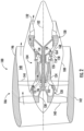
- FIG. 2 a schematic cross-sectional view of a gas turbine engine in accordance with one embodiment of the present disclosure is illustrated.
- turbomachinery in general, including turbojet, turboprop and turboshaft gas turbine engines, including industrial and marine gas turbine engines and auxiliary power units.
- the turbofan engine 100 has a longitudinal or axial centerline axis 102 that extends therethrough for reference purposes.
- the turbofan engine 100 may include a core turbine or gas turbine engine 104 disposed downstream from a fan section 106.
- the gas turbine engine 104 may generally include a substantially tubular outer casing 108 that defines an annular inlet 120.
- the outer casing 108 may be formed from multiple casings.
- the outer casing 108 encases, in serial flow relationship, a compressor section having a booster or low pressure (LP) compressor 122, a high pressure (HP) compressor 124, a combustion section 126, a turbine section including a high pressure (HP) turbine 128, a low pressure (LP) turbine 130, and a jet exhaust nozzle section 132.
- a high pressure (HP) shaft or spool 134 drivingly connects the HP turbine 128 to the HP compressor 124.
- a low pressure (LP) shaft or spool 136 drivingly connects the LP turbine 130 to the LP compressor 122.
- the LP spool 136 may also be connected to a fan spool or shaft 138 of the fan section 106.
- the LP spool 136 may be connected directly to the fan spool 138 such as in a direct-drive configuration.
- the LP spool 136 may be connected to the fan spool 138 via a speed reduction device 137 such as a reduction gear gearbox in an indirect-drive or geared-drive configuration.
- speed reduction devices may be included between any suitable shafts / spools within turbofan engine 100 as desired or required.
- the fan section 106 includes a plurality of fan blades 140 that are coupled to and that extend radially outwardly from the fan spool 138.
- An annular fan casing or nacelle 142 circumferentially surrounds the fan section 106 and/or at least a portion of the gas turbine engine 104.
- the nacelle 142 may be configured to be supported relative to the gas turbine engine 104 by a plurality of circumferentially-spaced outlet guide vanes 144.
- a downstream section 146 of the nacelle 142 downstream of the guide vanes 144) may extend over an outer portion of the gas turbine engine 104 so as to define a bypass airflow passage 148 there between.
- the HP turbine 128 includes, in serial flow relationship, a first stage of stator vanes 154 (only one shown) axially spaced from turbine rotor blades 158 (only one shown) (also referred to as “turbine blades”) and a second stage of stator vanes 164 (only one shown) axially spaced from turbine rotor blades 168 (only one shown) (also referred to as “turbine blades").
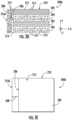
- FIGS. 3A-3C various views of embodiments of a CMC component 200A, 200B, 200C in accordance with an embodiment of the present disclosure are illustrated.
- FIG. 3A illustrates a cross-section of an embodiment of a CMC component 200A in accordance with one embodiment of the present disclosure.
- FIG. 3B illustrates a cross-section of an embodiment of CMC component 200B in accordance with another embodiment of the present disclosure.
- FIG. 3C illustrates a cross-section of an embodiment of a CMC component 200C in accordance with still another embodiment of the present disclosure.
- FIG. 3D illustrates a cross-section of the CMC component 200A of FIG.
- FIG. 3A in accordance with one embodiment of the present disclosure, particularly illustrating the CMC component 200A having a translaminar matrix crack 208 (also referred to herein as simply an edge crack 208).
- FIG. 3E illustrates a top view of the CMC component 200A of FIG. 3D , particularly illustrating the translaminar matrix crack 208 in the CMC component 200A spanning the plies 202, 204 thereof.
- the CMC components described herein 200A, 200B, 200C are laminated from unidirectional prepreg tape or constructed of a two-dimensional preform containing layers of aligned, continuous fibers and includes a plurality of CMC plies 202, 204.
- the plurality of plies 202, 204 include, at least, a first CMC ply 202 and a second CMC ply 204 stacked together to form a laminate structure 210 having at least one edge 206.
- the first CMC ply 202 may be one of a first set of CMC plies 202 and the second CMC ply 204 may be one of a second set of CMC plies 204.
- the first CMC ply 202 (or first set of CMC plies 202) are formed from a CMC material 212 reinforced with a fiber material 214 having a first fiber orientation.
- the first fiber orientation i.e., a direction of the individual fibers in the ply
- the second CMC ply 204 (or second set of CMC plies 204) are formed from the CMC material 212 reinforced with the fiber material 214 having a second fiber orientation.
- the second fiber orientation is parallel with direction Z of the coordinate axes that extends into or out of the page.
- the first and second CMC plies 202, 204 are stacked together in an alternating or cross-ply pattern in a plane (such as the X-Y plane) of the laminate structure 210.
- the first set of CMC plies 202 having the first fiber orientation may be alternated with the second set of CMC plies 204 having the second fiber orientation.
- the CMC components 200A, 200B, 200C described herein further includes at least one end cap ply 216A, 216B, 216C covering at least a portion of the edge 206 of the laminate structure 210.
- a single end cap ply 216A, 216B, 216C is illustrated in FIGS. 3A-3D for purposes of simplifying the figures, however, one of ordinary skill in the art would appreciate that the CMC components 200A, 200B, 200C may include a plurality of end cap plies 216A, 216B, 216C covering at least a portion of the edge 206.
- the end cap ply 216A, 216B, 216C may be laid up such that at least a portion of the end cap ply 216A, 216B, 216C completely covers the edge 206.
- the end cap ply 216B, 216C may be wrapped around the edge 206 and at least a portion of one or more of the first and second CMC plies 202, 204.
- the end cap ply 216B, 216C may be integral with the first CMC ply 202 or the second CMC ply 204.
- the end cap ply 216C is integral with one of the second CMC plies 204.
- the end cap ply 216A, 216B, 216C may be formed of the CMC material 212 reinforced with the fiber material 214 having a third fiber orientation.
- the third fiber orientation may be the same as the first fiber orientation of the first set of CMC plies 202.
- the third fiber orientation may be the same as the second fiber orientation of the second set of CMC plies 204.
- at least a portion of a plane of the end cap ply 216A, 216B, 216C is generally laid up perpendicular to a plane of the laminate structure 210.
- in-plane tensile stress on the edge 206 of the CMC component 200A can initiate the edge crack 208 or cause the edge crack 208 to grow from a pre-existing flaw or scratch.
- Such crack(s) 208 are generally resisted by bridging fibers running perpendicular to the crack plane (e.g., the fiber material 214 in the first CMC plies 202).
- bridging fibers running perpendicular to the crack plane e.g., the fiber material 214 in the first CMC plies 202
- half or more of the plies in the CMC component offer no bridging fibers to resist the edge 208, as shown particularly in FIGS.
- the end cap ply 216A is oriented such that the fiber material having the third fiber orientation in the end cap ply 216A is configured to bridge the edge crack 208 on or in the edge 206 of the laminate structure 210. Accordingly, in such embodiments, the end cap ply 216A is configured to at least double a resistance to edge cracks on or in the edge 206 and/or to resist a propagation of edge cracks.
- the CMC material 212 and the fiber material 214 of each of the first and second CMC plies and the end cap ply 216A, 216B, 216C are referred to herein as being the same material, one of ordinary skill in the art would recognize that such materials may also vary across plies.
- the first CMC ply may be formed of a first CMC material and/or a first fiber material
- the second CMC ply may be formed of a second CMC material and/or a second fiber material
- the end cap ply may be formed of a third CMC material and/or a third fiber material, with the first, second, and third CMC materials and/or the first, second, and third fiber materials in each ply being different.
- CMC materials described herein are generally low ductility and low coefficient of thermal expansion materials.
- CMC materials include a ceramic fiber, for example, a silicon carbide (SiC), forms of which are coated with a compliant material such as boron nitride (BN).
- the fiber materials may be coated in a ceramic type matrix, one form of which is silicon carbide (SiC).
- CMC materials generally have room temperature tensile ductility of less than or equal to about 1%. Generally, CMC materials have a room temperature tensile ductility in the range of about 0.4% to about 0.7%.
- CMC materials When formed into continuous-fiber plies, CMC materials have a characteristic wherein the tensile strength of the ply in the direction parallel to the length of the fibers (the "fiber direction") is stronger than the tensile strength in the direction perpendicular.
- This perpendicular direction may include matrix, interlaminar, secondary or tertiary fiber directions.
- Various physical properties may also differ between the fiber and the matrix directions.
- FIGS. 4A and 4B graphs 250, 350 of crack length (y-axis) versus cycles (x-axis) in accordance with various embodiments of the present disclosure are provided. Furthermore, FIGS. 4A and 4B illustrate a benefit of the end cap ply for the case of a fatigue crack that grows incrementally during each of many loading cycles for an embodiment of the present disclosure. In other embodiments, those skilled in the art will recognize that the end cap ply will contribute a similar crack-propagating inhibiting effect in the case of cracks that grow rapidly during a single load cycle.
- FIG. 4A illustrates a graph 250 of crack length (y-axis) versus cycles (x-axis) in accordance with one embodiment of the present disclosure, particularly illustrating CMC components under low loads with and without an end cap ply in which the CMC component having the end cap ply shows no crack propagation.
- FIG. 4B illustrates a graph 350 of crack length (y-axis) versus cycles (x-axis) for high loads in accordance with one embodiment of the present disclosure, particularly illustrating CMC components under high loads with and without an end cap ply in which the CMC components having the end cap ply has slower crack propagation over the same number of cycles as compared to CMC components without the end cap ply.
- CMC components with an end cap ply can more than double the fatigue life of the CMC component (e.g., as shown from 1000 to 2000 cycles) since the growth rate of the crack will be inhibited while it is within the end cap ply.
- FIG. 5 a flow diagram of an embodiment of a method 400 of forming a CMC component is provided.
- the method 400 can be used with respect to the CMC component(s) 200A, 200B, 200C or any other CMC component configuration.
- the exemplary method 400 is discussed herein only to describe exemplary aspects of the present disclosure and is not intended to be limiting.
- FIG. 5 depicts a method having steps performed in a particular order for purposes of illustration and discussion, those of ordinary skill in the art, using the disclosures provided herein, will understand that the steps of any of the methods discussed herein can be adapted, rearranged, expanded, omitted, or modified in various ways without deviating from the scope of the present disclosure.
- the method 400 includes stacking a plurality of CMC plies having, at least, a first CMC ply and a second CMC ply together to form a laminate structure, the first CMC ply being formed from a CMC material reinforced with a fiber material having a first fiber orientation, the second CMC ply being formed from the CMC material reinforced with the fiber material having a second fiber orientation, the first and second fiber orientations being arranged in a cross-ply pattern in a plane of in the laminate structure, the laminate structure comprising at least one edge.
- the method 400 includes arranging at least one end cap ply to cover at least a portion of the edge of the laminate structure, the at least one end cap ply being formed of the CMC material reinforced with the fiber material having a third fiber orientation, the at least one end cap ply being perpendicular to the plane of the laminate structure.
- the method 400 includes processing the laminate structure to form the CMC component.
- processing the laminate structure to form the CMC component may include compaction, burnout, melt infiltration, applying pressure to the CMC plies and/or the end cap ply, and/or applying heat to the CMC plies and the end cap ply to form the CMC component.
- FIG. 6 a flow diagram of an embodiment of a method 500 of upgrading or repairing a CMC component is provided.
- the method 500 can be used with respect to the CMC component(s) 200A, 200B, 200C or any other CMC component configuration.
- the exemplary method 500 is discussed herein only to describe exemplary aspects of the present disclosure and is not intended to be limiting.
- FIG. 6 depicts a method having steps performed in a particular order for purposes of illustration and discussion, those of ordinary skill in the art, using the disclosures provided herein, will understand that the steps of any of the methods discussed herein can be adapted, rearranged, expanded, omitted, or modified in various ways without deviating from the scope of the present disclosure.
- the method 500 includes arranging a plurality of CMC plies having, at least, a first CMC ply and a second CMC ply together to form the CMC component, the first CMC ply being formed from a CMC material reinforced with a fiber material having a first fiber orientation, the second CMC ply being formed from the CMC material reinforced with the fiber material having a second fiber orientation, the first and second fiber orientations being arranged in a cross-ply pattern in a plane of in the laminate structure, the laminate structure comprising at least one edge.
- the method 500 includes arranging at least one end cap ply to cover at least a portion of the edge of the CMC component, the at least one end cap ply being formed of the CMC material reinforced with the fiber material having a third fiber orientation, the at least one end cap ply being perpendicular to the plane of the laminate structure.
- the method 500 also includes processing the laminate structure to upgrade or repair the CMC component.
- processing the laminate structure to form the CMC component may include compaction, burnout, melt infiltration, applying pressure to the CMC plies and/or the end cap ply, and/or applying heat to the CMC plies and the end cap ply to form the CMC component.
- a ceramic matrix composite (CMC) component comprising: a plurality of CMC plies comprising, at least, a first CMC ply and a second CMC ply stacked together to form a laminate structure, the first CMC ply being formed from a CMC material reinforced with a fiber material having a first fiber orientation, the second CMC ply being formed from the CMC material reinforced with the fiber material having a second fiber orientation, the first and second fiber orientations being arranged in a cross-ply pattern in a plane of the laminate structure, the laminate structure comprising at least one edge; and at least one end cap ply covering at least a portion of the at least one edge of the laminate structure, the at least one end cap ply being formed of the CMC material reinforced with the fiber material having a third fiber orientation, wherein the at least one end cap ply is perpendicular to the plane of the laminate structure.
- CMC ceramic matrix composite
- the at least one end cap ply is oriented such that the fiber material having the third fiber orientation in the at least one end cap ply is configured to bridge a translaminar matrix crack on or in the laminate structure.
- the CMC component of any preceding clause further comprising a plurality of end cap plies covering at least a portion of the at least one edge, wherein the at least one end cap ply is one of the plurality of end cap plies.
- first CMC ply is part of a first set of CMC plies and the second CMC ply is part of a second set of CMC plies, the first and second fiber orientations of the first and second sets of CMC plies being arranged in the cross-ply pattern.
- a component of a gas turbine engine comprising the CMC component of any preceding clause.
- a method of forming a ceramic matrix composite (CMC) component comprising: stacking a plurality of CMC plies having, at least, a first CMC ply and a second CMC ply together to form a laminate structure, the first CMC ply being formed from a CMC material reinforced with a fiber material having a first fiber orientation, the second CMC ply being formed from the CMC material reinforced with the fiber material having a second fiber orientation, the first and second fiber orientations being arranged in a cross-ply pattern in a plane of in the laminate structure, the laminate structure comprising at least one edge; arranging at least one end cap ply to cover at least a portion of the at least one edge of the laminate structure, the at least one end cap ply being formed of the CMC material reinforced with the fiber material having a third fiber orientation, at least a portion of a plane of the at least one end cap ply being perpendicular to the plane of the laminate structure; and processing the laminate structure to form the CMC component.
- the at least one end cap ply is oriented such that the fiber material having the third fiber orientation in the at least one end cap ply is configured to bridge a translaminar matrix crack on or in the laminate structure.
- the at least one end cap ply is one of a plurality of end cap plies, the method further comprising arranging the plurality of end cap plies to cover at least the portion of the at least one edge of the laminate structure.
- first CMC ply is part of a first set of CMC plies and the second CMC ply is part of a second set of CMC plies, the first and second fiber orientations of the first and second sets of CMC plies being arranged in the cross-ply pattern.
- a method of upgrading or repairing a ceramic matrix composite (CMC) component comprising: arranging a plurality of CMC plies having, at least, a first CMC ply and a second CMC ply together to form a laminate structure, the first CMC ply being formed from a CMC material reinforced with a fiber material having a first fiber orientation, the second CMC ply being formed from the CMC material reinforced with the fiber material having a second fiber orientation, the first and second fiber orientations being arranged in a cross-ply pattern in a plane of the laminate structure, the laminate structure comprising at least one edge; arranging at least one end cap ply to cover at least a portion of the at least one edge of the CMC component, the at least one end cap ply being formed of the CMC material reinforced with the fiber material having a third fiber orientation, at least a portion of a plane of the at least one end cap ply being perpendicular to the plane of the laminate structure; and processing the laminate structure to form the CMC component
Landscapes
- Engineering & Computer Science (AREA)
- Chemical & Material Sciences (AREA)
- Ceramic Engineering (AREA)
- Combustion & Propulsion (AREA)
- Mechanical Engineering (AREA)
- General Engineering & Computer Science (AREA)
- Chemical Kinetics & Catalysis (AREA)
- Manufacturing & Machinery (AREA)
- Materials Engineering (AREA)
- Structural Engineering (AREA)
- Organic Chemistry (AREA)
- Laminated Bodies (AREA)
Abstract
A ceramic matrix composite (CMC) component (200A, 200B, 200CB) includes a plurality of CMC plies (202, 204) stacked together to form a laminate structure (210). First and second CMC plies (202, 204) of the laminate structure (210) are formed from a CMC material (212) reinforced with a fiber material (214) and have first and second fiber orientations, respectively. The first and second fiber orientations are arranged in a cross-ply pattern in a plane of the laminate structure (210). The laminate structure (210) includes at least one edge (206). The CMC component (200A, 200B, 200C) further includes at least one end cap ply (216A, 216B, 216C) covering at least a portion of the at least one edge (206) of the laminate structure (216A, 216B, 216C). The end cap ply (216A, 216B, 216C) is formed of the CMC material (212) reinforced with the fiber material (214) having a third fiber orientation. Further, at least a portion of a plane of the at least one end cap ply (216A, 216B, 216C) is perpendicular to the plane of the laminate structure (210).
Description
- The present disclosure relates generally to ceramic matrix composites, and more particularly to ceramic matrix composites resistant to edge cracks, which are particularly useful as components for gas turbine engines.
- The design of modem gas turbine engines is driven by the demand for higher turbine efficiency. It is therefore desirable to operate the turbines at the highest possible temperatures. For any engine cycle compression ratio or bypass ratio, increasing the turbine entry gas temperature produces more specific thrust (e.g., engine thrust per unit of air mass flow). However, as turbine entry temperatures increase, it is necessary to develop components and materials better able to withstand the increased temperatures. Accordingly, ceramic matrix composites ("CMCs") are an attractive material for turbine applications, as CMCs have high temperature capability and are light weight.
- CMCs can be manufactured using a variety of techniques. For example, CMC components may be laminated from unidirectional prepreg tape, having at least one edge perpendicular to the plane of the tape. In such configurations, however, in-plane tensile stress on the edge can initiate a translaminar matrix crack and/or cause such a crack to grow from a pre-existing flaw or scratch. Thus, an improved design for CMC laminates that is resistant to edge cracks is desirable in the art.
- A full and enabling disclosure of the present embodiments, including the best mode thereof, directed to one of ordinary skill in the art, is set forth in the specification, which makes reference to the appended figures, in which:
-
FIG. 1A is a cross-section of a CMC component in accordance with conventional construction; -
FIG. 1B is a cross-section of a CMC component in accordance with conventional construction, particularly illustrating the CMC component having an edge crack; -
FIG. 1C is a top view of the CMC component ofFIG. 1B , particularly illustrating the edge crack in the CMC component; -
FIG. 2 is a cross-section of an exemplary gas turbine engine in accordance with one embodiment of the present disclosure; -
FIG. 3A is a cross-section of a CMC component in accordance with one embodiment of the present disclosure; -
FIG. 3B illustrates a cross-section of a CMC component in accordance with another embodiment of the present disclosure; -
FIG. 3C illustrates a cross-section of a CMC component in accordance with still another embodiment of the present disclosure; -
FIG. 3D is a cross-section of a CMC component in accordance with one embodiment of the present disclosure, particularly illustrating the CMC component having an edge crack; -
FIG. 3E is a top view of the CMC component ofFIG. 3C , particularly illustrating the edge crack in the CMC component; -
FIG. 4A is a graph of crack length (y-axis) versus cycles (x-axis) in accordance with one embodiment of the present disclosure, particularly illustrating CMC components under low loads with and without an end cap ply in which the CMC component having the end cap ply shows no crack propagation; -
FIG. 4B is a graph of crack length (y-axis) versus cycles (x-axis) for high loads in accordance with one embodiment of the present disclosure, particularly illustrating CMC components under high loads with and without an end cap ply in which the CMC components having the end cap ply has slower crack propagation over the same number of cycles as compared to CMC components without the end cap ply; -
FIG. 5 is a flowchart of an exemplary method of forming a CMC component in accordance with one embodiment of the present disclosure; and -
FIG. 6 is a flowchart of an exemplary method of upgrading or repairing a CMC component in accordance with one embodiment of the present disclosure. - Repeat use of reference characters in the present specification and drawings is intended to represent the same or analogous features or elements of the present invention.
- Reference now will be made in detail to embodiments of the present disclosure, one or more examples of which are illustrated in the drawings. Each example is provided by way of explanation of the embodiments disclosed herein, not limitation thereof. In fact, it will be apparent to those skilled in the art that various modifications and variations can be made to the embodiments of the present disclosure without departing from the scope or spirit of the various embodiments described. For instance, features illustrated or described as part of one embodiment can be used with another embodiment to yield a still further embodiment. Thus, it is intended that the present disclosure covers such modifications and variations as come within the scope of the appended claims and their equivalents.
- Generally, the present disclosure is directed to ceramic matrix composite ("CMC") components resistant to edge cracks and/or propagation of edge cracks. CMC components laminated from unidirectional prepreg tape or from a two-dimensional preform containing layers of aligned, continuous fibers usually have at least one edge perpendicular to the lamination plane, which may be referred to herein as an "exposed edge". For example, as shown in
FIG. 1A , an example cross-section of aCMC component 10 in accordance with conventional construction is illustrated. Further, as shown, theCMC component 10 includesmultiple plies FIGS. 1B and 1C , in-plane tensile stress on an exposededge 16 of theCMC component 10 can initiate atranslaminar matrix crack 18 or cause one to grow from a pre-existing flaw or scratch. As used herein, "translaminar" generally refers to the plane of the main laminate or stack of aligned fibers. Such cracks can grow rapidly during a single loading cycle or can grow incrementally during each cycle, as a fatigue crack. Further, thetranslaminar matrix cracks 18 are generally resisted by bridging fibers running perpendicular to the crack plane. However, for one or more design purposes, and as shown inFIGS. 1A and 1B , it may be desirable to orient half or more of the plies (e.g., such as plies 12) in theCMC component 10 such that they offer no bridging fibers to resist a translaminar crack on the exposededge 16. Thus, the resistance to thetranslaminar matrix crack 18 on the exposededge 16 can be half or less than that of a component in which the maximum number of bridging fibers were presented. - The exposed edge(s) are frequently the location of cracks that limit the useful life of CMC components. Accordingly, the present disclosure is configured to increase (e.g., by doubling or more) the resistance to edge cracks and prolong the useful life of the components. In particular, as will be explained herein, the present disclosure is directed to a CMC component having one or more end cap plies added to the exposed edge(s) thereof. In certain embodiments, for example, an end cap ply can be laid up perpendicular to the basic laminate plane such that the end cap ply covers the exposed edge(s). Furthermore, in an embodiment, the one or more end cap plies can be oriented such that all of the fibers therein can bridge a translaminar matrix crack on or in the laminate structure. Thus, in a typical situation where half the plies in the basic laminate offer no bridging fiber to edge cracks, the end cap ply is configured to at least double the resistance to edge cracks.
- The systems and methods of the present disclosure can be used to prepare a variety of components including ceramic matrix composites. For instance, the systems and methods of the present disclosure may be used to prepare components in the aviation industry. Further, the systems and methods of the present disclosure may be used to prepare components for gas turbine engines, such as in high pressure compressors (HPC), fans, boosters, high pressure turbines (HPT), and low pressure turbines (LPT) of both airborne and land-based gas turbine engines. For instance, the systems and methods of the present disclosure may be used to prepare components for a turbofan engine or turbomachinery in general, including turbojet, turboprop and turboshaft gas turbine engines, including industrial and marine gas turbine engines and auxiliary power units. For instance, components such as combustion liners, shrouds, nozzles, blades, etc. may be prepared with the present method and materials.
- Referring now to
FIG. 2 , a schematic cross-sectional view of a gas turbine engine in accordance with one embodiment of the present disclosure is illustrated. Although further described below generally with reference to aturbofan engine 100, the present disclosure is also applicable to turbomachinery in general, including turbojet, turboprop and turboshaft gas turbine engines, including industrial and marine gas turbine engines and auxiliary power units. - As shown in
FIG. 2 , theturbofan engine 100 has a longitudinal oraxial centerline axis 102 that extends therethrough for reference purposes. In general, theturbofan engine 100 may include a core turbine orgas turbine engine 104 disposed downstream from a fan section 106. - The
gas turbine engine 104 may generally include a substantially tubularouter casing 108 that defines anannular inlet 120. Theouter casing 108 may be formed from multiple casings. Theouter casing 108 encases, in serial flow relationship, a compressor section having a booster or low pressure (LP)compressor 122, a high pressure (HP)compressor 124, acombustion section 126, a turbine section including a high pressure (HP)turbine 128, a low pressure (LP)turbine 130, and a jetexhaust nozzle section 132. A high pressure (HP) shaft orspool 134 drivingly connects theHP turbine 128 to theHP compressor 124. A low pressure (LP) shaft orspool 136 drivingly connects theLP turbine 130 to theLP compressor 122. TheLP spool 136 may also be connected to a fan spool orshaft 138 of the fan section 106. In particular embodiments, theLP spool 136 may be connected directly to thefan spool 138 such as in a direct-drive configuration. In alternative configurations, theLP spool 136 may be connected to thefan spool 138 via aspeed reduction device 137 such as a reduction gear gearbox in an indirect-drive or geared-drive configuration. Such speed reduction devices may be included between any suitable shafts / spools withinturbofan engine 100 as desired or required. - As shown in
FIG. 3 , the fan section 106 includes a plurality offan blades 140 that are coupled to and that extend radially outwardly from thefan spool 138. An annular fan casing ornacelle 142 circumferentially surrounds the fan section 106 and/or at least a portion of thegas turbine engine 104. It should be appreciated by those of ordinary skill in the art that thenacelle 142 may be configured to be supported relative to thegas turbine engine 104 by a plurality of circumferentially-spaced outlet guide vanes 144. Moreover, adownstream section 146 of the nacelle 142 (downstream of the guide vanes 144) may extend over an outer portion of thegas turbine engine 104 so as to define abypass airflow passage 148 there between. - The
HP turbine 128 includes, in serial flow relationship, a first stage of stator vanes 154 (only one shown) axially spaced from turbine rotor blades 158 (only one shown) (also referred to as "turbine blades") and a second stage of stator vanes 164 (only one shown) axially spaced from turbine rotor blades 168 (only one shown) (also referred to as "turbine blades"). - Referring now to
FIGS. 3A-3C , various views of embodiments of aCMC component FIG. 3A illustrates a cross-section of an embodiment of aCMC component 200A in accordance with one embodiment of the present disclosure.FIG. 3B illustrates a cross-section of an embodiment ofCMC component 200B in accordance with another embodiment of the present disclosure.FIG. 3C illustrates a cross-section of an embodiment of a CMC component 200C in accordance with still another embodiment of the present disclosure.FIG. 3D illustrates a cross-section of theCMC component 200A ofFIG. 3A in accordance with one embodiment of the present disclosure, particularly illustrating theCMC component 200A having a translaminar matrix crack 208 (also referred to herein as simply an edge crack 208).FIG. 3E illustrates a top view of theCMC component 200A ofFIG. 3D , particularly illustrating thetranslaminar matrix crack 208 in theCMC component 200A spanning theplies - More particularly, as shown, the CMC components described herein 200A, 200B, 200C are laminated from unidirectional prepreg tape or constructed of a two-dimensional preform containing layers of aligned, continuous fibers and includes a plurality of CMC plies 202, 204. For example, as shown, the plurality of
plies laminate structure 210 having at least oneedge 206. In an embodiment, for example, the first CMC ply 202 may be one of a first set of CMC plies 202 and the second CMC ply 204 may be one of a second set of CMC plies 204. - Furthermore, in an embodiment, the first CMC ply 202 (or first set of CMC plies 202) are formed from a
CMC material 212 reinforced with afiber material 214 having a first fiber orientation. For example, as shown inFIGS. 3A-3D , the first fiber orientation (i.e., a direction of the individual fibers in the ply) is parallel with direction X of the coordinate axes. Moreover, as shown, the second CMC ply 204 (or second set of CMC plies 204) are formed from theCMC material 212 reinforced with thefiber material 214 having a second fiber orientation. However, as shown inFIGS. 3A-3D , the second fiber orientation is parallel with direction Z of the coordinate axes that extends into or out of the page. Thus, as shown inFIGS. 3A-3D , the first and second CMC plies 202, 204 are stacked together in an alternating or cross-ply pattern in a plane (such as the X-Y plane) of thelaminate structure 210. In other words, as shown, the first set of CMC plies 202 having the first fiber orientation may be alternated with the second set of CMC plies 204 having the second fiber orientation. - Still referring to
FIGS. 3A-3E , theCMC components edge 206 of thelaminate structure 210. It should be understood that a single end cap ply 216A, 216B, 216C is illustrated inFIGS. 3A-3D for purposes of simplifying the figures, however, one of ordinary skill in the art would appreciate that theCMC components edge 206. Moreover, as shown inFIGS. 3A-3D , the end cap ply 216A, 216B, 216C may be laid up such that at least a portion of the end cap ply 216A, 216B, 216C completely covers theedge 206. In further embodiments, as shown inFIGS. 3B and 3C , theend cap ply edge 206 and at least a portion of one or more of the first and second CMC plies 202, 204. Moreover, in another embodiment, theend cap ply FIG. 3C , theend cap ply 216C is integral with one of the second CMC plies 204. - Moreover, similar to the first and second CMC plies 202, 204, the end cap ply 216A, 216B, 216C may be formed of the
CMC material 212 reinforced with thefiber material 214 having a third fiber orientation. In an embodiment, as shown, the third fiber orientation may be the same as the first fiber orientation of the first set of CMC plies 202. In another embodiment, the third fiber orientation may be the same as the second fiber orientation of the second set of CMC plies 204. In addition, as shown, at least a portion of a plane of the end cap ply 216A, 216B, 216C is generally laid up perpendicular to a plane of thelaminate structure 210. - As shown in
FIGS. 3D and 3E , in-plane tensile stress on theedge 206 of theCMC component 200A can initiate theedge crack 208 or cause theedge crack 208 to grow from a pre-existing flaw or scratch. Such crack(s) 208 are generally resisted by bridging fibers running perpendicular to the crack plane (e.g., thefiber material 214 in the first CMC plies 202). However, in instances where half or more of the plies in the CMC component offer no bridging fibers to resist theedge 208, as shown particularly inFIGS. 3D and 3E , the end cap ply 216A is oriented such that the fiber material having the third fiber orientation in the end cap ply 216A is configured to bridge theedge crack 208 on or in theedge 206 of thelaminate structure 210. Accordingly, in such embodiments, the end cap ply 216A is configured to at least double a resistance to edge cracks on or in theedge 206 and/or to resist a propagation of edge cracks. - Though the
CMC material 212 and thefiber material 214 of each of the first and second CMC plies and the end cap ply 216A, 216B, 216C are referred to herein as being the same material, one of ordinary skill in the art would recognize that such materials may also vary across plies. Thus, the first CMC ply may be formed of a first CMC material and/or a first fiber material, the second CMC ply may be formed of a second CMC material and/or a second fiber material, and the end cap ply may be formed of a third CMC material and/or a third fiber material, with the first, second, and third CMC materials and/or the first, second, and third fiber materials in each ply being different. - Furthermore, the CMC materials described herein are generally low ductility and low coefficient of thermal expansion materials. In addition, typically, CMC materials include a ceramic fiber, for example, a silicon carbide (SiC), forms of which are coated with a compliant material such as boron nitride (BN). The fiber materials may be coated in a ceramic type matrix, one form of which is silicon carbide (SiC). In addition, CMC materials generally have room temperature tensile ductility of less than or equal to about 1%. Generally, CMC materials have a room temperature tensile ductility in the range of about 0.4% to about 0.7%. When formed into continuous-fiber plies, CMC materials have a characteristic wherein the tensile strength of the ply in the direction parallel to the length of the fibers (the "fiber direction") is stronger than the tensile strength in the direction perpendicular. This perpendicular direction may include matrix, interlaminar, secondary or tertiary fiber directions. Various physical properties may also differ between the fiber and the matrix directions.
- Referring now to
FIGS. 4A and 4B ,graphs FIGS. 4A and 4B illustrate a benefit of the end cap ply for the case of a fatigue crack that grows incrementally during each of many loading cycles for an embodiment of the present disclosure. In other embodiments, those skilled in the art will recognize that the end cap ply will contribute a similar crack-propagating inhibiting effect in the case of cracks that grow rapidly during a single load cycle. - In particular,
FIG. 4A illustrates agraph 250 of crack length (y-axis) versus cycles (x-axis) in accordance with one embodiment of the present disclosure, particularly illustrating CMC components under low loads with and without an end cap ply in which the CMC component having the end cap ply shows no crack propagation.FIG. 4B illustrates agraph 350 of crack length (y-axis) versus cycles (x-axis) for high loads in accordance with one embodiment of the present disclosure, particularly illustrating CMC components under high loads with and without an end cap ply in which the CMC components having the end cap ply has slower crack propagation over the same number of cycles as compared to CMC components without the end cap ply. Thus, as shown ingraph 250 ofFIG. 4A , for lower loading scenarios, crack length increases with increasing loading cycles in CMC components without an end cap ply (represented by curve 252) versus CMC components with an end cap ply (represented by curve 254). In other words, for lower loading scenarios, the fatigue life of CMC components with an end cap ply is significantly improved since the crack generally cannot propagate beyond the end cap ply. Moreover, as shown ingraph 350 ofFIG. 4B , for higher loading scenarios, crack length increases with increasing loading cycles in CMC components without an end cap ply (represented by curve 352) at a faster rate than CMC components with an end cap ply (represented by curve 354). In other words, for higher loading scenarios, CMC components with an end cap ply can more than double the fatigue life of the CMC component (e.g., as shown from 1000 to 2000 cycles) since the growth rate of the crack will be inhibited while it is within the end cap ply. - Referring now to
FIG. 5 , a flow diagram of an embodiment of amethod 400 of forming a CMC component is provided. In particular, themethod 400 can be used with respect to the CMC component(s) 200A, 200B, 200C or any other CMC component configuration. However, it should be appreciated that theexemplary method 400 is discussed herein only to describe exemplary aspects of the present disclosure and is not intended to be limiting. Further, thoughFIG. 5 depicts a method having steps performed in a particular order for purposes of illustration and discussion, those of ordinary skill in the art, using the disclosures provided herein, will understand that the steps of any of the methods discussed herein can be adapted, rearranged, expanded, omitted, or modified in various ways without deviating from the scope of the present disclosure. - As shown at (402), the
method 400 includes stacking a plurality of CMC plies having, at least, a first CMC ply and a second CMC ply together to form a laminate structure, the first CMC ply being formed from a CMC material reinforced with a fiber material having a first fiber orientation, the second CMC ply being formed from the CMC material reinforced with the fiber material having a second fiber orientation, the first and second fiber orientations being arranged in a cross-ply pattern in a plane of in the laminate structure, the laminate structure comprising at least one edge. As shown at (404), themethod 400 includes arranging at least one end cap ply to cover at least a portion of the edge of the laminate structure, the at least one end cap ply being formed of the CMC material reinforced with the fiber material having a third fiber orientation, the at least one end cap ply being perpendicular to the plane of the laminate structure. As shown at (406), themethod 400 includes processing the laminate structure to form the CMC component. For example, in an embodiment, processing the laminate structure to form the CMC component may include compaction, burnout, melt infiltration, applying pressure to the CMC plies and/or the end cap ply, and/or applying heat to the CMC plies and the end cap ply to form the CMC component. - Referring now to
FIG. 6 , a flow diagram of an embodiment of amethod 500 of upgrading or repairing a CMC component is provided. In particular, themethod 500 can be used with respect to the CMC component(s) 200A, 200B, 200C or any other CMC component configuration. However, it should be appreciated that theexemplary method 500 is discussed herein only to describe exemplary aspects of the present disclosure and is not intended to be limiting. Further, thoughFIG. 6 depicts a method having steps performed in a particular order for purposes of illustration and discussion, those of ordinary skill in the art, using the disclosures provided herein, will understand that the steps of any of the methods discussed herein can be adapted, rearranged, expanded, omitted, or modified in various ways without deviating from the scope of the present disclosure. - As shown at (502), the
method 500 includes arranging a plurality of CMC plies having, at least, a first CMC ply and a second CMC ply together to form the CMC component, the first CMC ply being formed from a CMC material reinforced with a fiber material having a first fiber orientation, the second CMC ply being formed from the CMC material reinforced with the fiber material having a second fiber orientation, the first and second fiber orientations being arranged in a cross-ply pattern in a plane of in the laminate structure, the laminate structure comprising at least one edge. As shown at (504), themethod 500 includes arranging at least one end cap ply to cover at least a portion of the edge of the CMC component, the at least one end cap ply being formed of the CMC material reinforced with the fiber material having a third fiber orientation, the at least one end cap ply being perpendicular to the plane of the laminate structure. As shown at (506), themethod 500 also includes processing the laminate structure to upgrade or repair the CMC component. For example, as mentioned, processing the laminate structure to form the CMC component may include compaction, burnout, melt infiltration, applying pressure to the CMC plies and/or the end cap ply, and/or applying heat to the CMC plies and the end cap ply to form the CMC component. - Further aspects of the present disclosure are provided by the subject matter of the following clauses:
A ceramic matrix composite (CMC) component, comprising: a plurality of CMC plies comprising, at least, a first CMC ply and a second CMC ply stacked together to form a laminate structure, the first CMC ply being formed from a CMC material reinforced with a fiber material having a first fiber orientation, the second CMC ply being formed from the CMC material reinforced with the fiber material having a second fiber orientation, the first and second fiber orientations being arranged in a cross-ply pattern in a plane of the laminate structure, the laminate structure comprising at least one edge; and at least one end cap ply covering at least a portion of the at least one edge of the laminate structure, the at least one end cap ply being formed of the CMC material reinforced with the fiber material having a third fiber orientation, wherein the at least one end cap ply is perpendicular to the plane of the laminate structure. - The CMC component of any preceding clause, wherein the at least one end cap ply is laid up such that the at least one end cap ply completely covers the at least one edge.
- The CMC component of any preceding clause, wherein the at least one end cap ply is wrapped around the at least one edge and at least a portion of each of the first and second CMC plies.
- The CMC component of any preceding clause, wherein the at least one end cap ply is oriented such that the fiber material having the third fiber orientation in the at least one end cap ply is configured to bridge a translaminar matrix crack on or in the laminate structure.
- The CMC component of any preceding clause, wherein the at least one end cap ply at least doubles a resistance to edge cracks in the at least one edge.
- The CMC component of any preceding clause, wherein the at least one end cap ply is integral with at least one of the first CMC ply or the second CMC ply.
- The CMC component of any preceding clause, further comprising a plurality of end cap plies covering at least a portion of the at least one edge, wherein the at least one end cap ply is one of the plurality of end cap plies.
- The CMC component of any preceding clause, wherein the first CMC ply is part of a first set of CMC plies and the second CMC ply is part of a second set of CMC plies, the first and second fiber orientations of the first and second sets of CMC plies being arranged in the cross-ply pattern.
- A component of a gas turbine engine comprising the CMC component of any preceding clause.
- A method of forming a ceramic matrix composite (CMC) component, the method comprising: stacking a plurality of CMC plies having, at least, a first CMC ply and a second CMC ply together to form a laminate structure, the first CMC ply being formed from a CMC material reinforced with a fiber material having a first fiber orientation, the second CMC ply being formed from the CMC material reinforced with the fiber material having a second fiber orientation, the first and second fiber orientations being arranged in a cross-ply pattern in a plane of in the laminate structure, the laminate structure comprising at least one edge; arranging at least one end cap ply to cover at least a portion of the at least one edge of the laminate structure, the at least one end cap ply being formed of the CMC material reinforced with the fiber material having a third fiber orientation, at least a portion of a plane of the at least one end cap ply being perpendicular to the plane of the laminate structure; and processing the laminate structure to form the CMC component.
- The method of any preceding clause, further comprising laying up the at least one end cap ply such that the at least one end cap ply completely covers the at least one edge.
- The method of any preceding clause, further comprising wrapping the at least one end cap ply around the at least one edge and at least a portion of each of the first and second CMC plies.
- The method of any preceding clause, wherein the at least one end cap ply is oriented such that the fiber material having the third fiber orientation in the at least one end cap ply is configured to bridge a translaminar matrix crack on or in the laminate structure.
- The method of any preceding clause, wherein the at least one end cap ply at least doubles a resistance to edge cracks in the at least one edge.
- The method of any preceding clause, wherein the at least one end cap ply is integral with at least one of the first CMC ply or the second CMC ply.
- The method of any preceding clause, wherein the at least one end cap ply is one of a plurality of end cap plies, the method further comprising arranging the plurality of end cap plies to cover at least the portion of the at least one edge of the laminate structure.
- The method of any preceding clause, wherein the first CMC ply is part of a first set of CMC plies and the second CMC ply is part of a second set of CMC plies, the first and second fiber orientations of the first and second sets of CMC plies being arranged in the cross-ply pattern.
- A method of upgrading or repairing a ceramic matrix composite (CMC) component, the method comprising: arranging a plurality of CMC plies having, at least, a first CMC ply and a second CMC ply together to form a laminate structure, the first CMC ply being formed from a CMC material reinforced with a fiber material having a first fiber orientation, the second CMC ply being formed from the CMC material reinforced with the fiber material having a second fiber orientation, the first and second fiber orientations being arranged in a cross-ply pattern in a plane of the laminate structure, the laminate structure comprising at least one edge; arranging at least one end cap ply to cover at least a portion of the at least one edge of the CMC component, the at least one end cap ply being formed of the CMC material reinforced with the fiber material having a third fiber orientation, at least a portion of a plane of the at least one end cap ply being perpendicular to the plane of the laminate structure; and processing the laminate structure to form the CMC component.
- The method of any preceding clause, further comprising laying up the at least one end cap ply such that the at least one end cap ply completely covers the at least one edge.
- The method of any preceding clause, further comprising wrapping the at least one end cap ply around the at least one edge and at least a portion of each of the first and second CMC plies.
- This written description uses examples to disclose the present disclosure, including the best mode, and also to enable any person skilled in the art to practice the present disclosure, including making and using any devices or systems and performing any incorporated methods. The patentable scope of the present disclosure is defined by the claims, and may include other examples that occur to those skilled in the art. Such other examples are intended to be within the scope of the claims if they include structural elements that do not differ from the literal language of the claims, or if they include equivalent structural elements with insubstantial differences from the literal languages of the claims.
Claims (15)
- A ceramic matrix composite (CMC) component (200A, 200B, 200CA, 200A, 200B, 200CB, 200A, 200B, 200CC), comprising:a plurality of CMC plies comprising, at least, a first CMC ply (202) and a second CMC ply (204) stacked together to form a laminate structure (210),the first CMC ply (202) being formed from a CMC material (212) reinforced with a fiber material (214) having a first fiber orientation, the second CMC ply (204) being formed from the CMC material (212) reinforced with the fiber material (214) having a second fiber orientation,the first and second fiber orientations being arranged in a cross-ply pattern in a plane of the laminate structure (210), the laminate structure (210) comprising at least one edge (206); andat least one end cap ply (216A, 216B, 216C) covering at least a portion of the at least one edge (206) of the laminate structure (210), the at least one end cap ply (216A, 216B, 216C) being formed of the CMC material (212) reinforced with the fiber material (214) having a third fiber orientation,wherein at least a portion of a plane of the at least one end cap ply (216A, 216B, 216C) is perpendicular to the plane of the laminate structure (210).
- The CMC component (200A, 200B, 200C) of claim 1, wherein the at least one end cap ply (216A, 216B, 216C) is laid up such that the at least one end cap ply (216A, 216B, 216C) completely covers the at least one edge (206).
- The CMC component (200A, 200B, 200C) of any preceding claim, wherein the at least one end cap ply (216A, 216B, 216C) is wrapped around the at least one edge (206) and at least a portion of each of the first and second CMC plies (202, 204).
- The CMC component (200A, 200B, 200C) of any preceding claim, wherein the at least one end cap ply (216A, 216B, 216C) is oriented such that the fiber material (214) having the third fiber orientation in the at least one end cap ply (216A, 216B, 216C) is configured to bridge a translaminar matrix crack (208) on or in the laminate structure (210).
- The CMC component (200A, 200B, 200C) of any preceding claim, wherein the at least one end cap ply (216A, 216B, 216C) at least doubles a resistance to edge cracks in the at least one edge (206).
- The CMC component (200A, 200B, 200C) of any preceding claim, wherein the at least one end cap ply (216A, 216B, 216C) is integral with at least one of the first CMC ply (202) or the second CMC ply (204).
- The CMC component (200A, 200B, 200C) of any preceding claim, further comprising a plurality of end cap plies covering at least a portion of the at least one edge (206), wherein the at least one end cap ply (216A, 216B, 216C) is one of the plurality of end cap plies.
- The CMC component (200A, 200B, 200C) of any preceding claim, wherein the first CMC ply (202) is part of a first set of CMC plies and the second CMC ply (204) is part of a second set of CMC plies, the first and second fiber orientations of the first and second sets of CMC plies being arranged in the cross-ply pattern.
- A component of a gas turbine engine comprising the CMC component (200A, 200B, 200C) of any preceding claim.
- A method (400) of forming a ceramic matrix composite (CMC) component, the method (400) comprising:stacking a plurality of CMC plies having, at least, a first CMC ply (202) and a second CMC ply (204) together to form a laminate structure (210), the first CMC ply (202) being formed from a CMC material (212) reinforced with a fiber material (214) having a first fiber orientation, the second CMC ply (204) being formed from the CMC material (212) reinforced with the fiber material (214) having a second fiber orientation, the first and second fiber orientations being arranged in a cross-ply pattern in a plane of in the laminate structure (210), the laminate structure (210) comprising at least one edge (206);arranging at least one end cap ply (216A, 216B, 216C) to cover at least a portion of the at least one edge (206) of the laminate structure (210), the at least one end cap ply (216A, 216B, 216C) being formed of the CMC material (212) reinforced with the fiber material (214) having a third fiber orientation, at least a portion of a plane of the at least one end cap ply (216A, 216B, 216C) being perpendicular to the plane of the laminate structure (210); andprocessing the laminate structure (210) to form the CMC component (200A, 200B, 200C).
- The method (400) of claim 10, further comprising laying up the at least one end cap ply (216A, 216B, 216C) such that the at least one end cap ply (216A, 216B, 216C) completely covers the at least one edge (206).
- The method (400) of claims 10 or 11, further comprising wrapping the at least one end cap ply (216A, 216B, 216C) around the at least one edge (206) and at least a portion of each of the first and second CMC plies (202, 204).
- The method (400) of any of claims 10-12, wherein the at least one end cap ply (216A, 216B, 216C) is oriented such that the fiber material (214) having the third fiber orientation in the at least one end cap ply (216A, 216B, 216C) is configured to bridge a translaminar matrix crack (208) on or in the laminate structure (210).
- The method (400) of any of claims 10-13, wherein the at least one end cap ply (216A, 216B, 216C) at least doubles a resistance to edge cracks in the at least one edge (206).
- The method (400) of any of claims 10-14, wherein the at least one end cap ply (216A, 216B, 216C) is integral with at least one of the first CMC ply (202) or the second CMC ply (204).
Applications Claiming Priority (1)
| Application Number | Priority Date | Filing Date | Title |
|---|---|---|---|
| US18/307,064 US12304177B2 (en) | 2023-04-26 | 2023-04-26 | Ceramic matrix composite (CMC) component resistant to edge cracks |
Publications (1)
| Publication Number | Publication Date |
|---|---|
| EP4454880A1 true EP4454880A1 (en) | 2024-10-30 |
Family
ID=90718137
Family Applications (1)
| Application Number | Title | Priority Date | Filing Date |
|---|---|---|---|
| EP24168522.1A Pending EP4454880A1 (en) | 2023-04-26 | 2024-04-04 | Ceramic matrix composite (cmc) component resistant to edge cracks |
Country Status (3)
| Country | Link |
|---|---|
| US (1) | US12304177B2 (en) |
| EP (1) | EP4454880A1 (en) |
| CN (1) | CN118849556A (en) |
Citations (3)
| Publication number | Priority date | Publication date | Assignee | Title |
|---|---|---|---|---|
| US20070075455A1 (en) * | 2005-10-04 | 2007-04-05 | Siemens Power Generation, Inc. | Method of sealing a free edge of a composite material |
| GB2521736A (en) * | 2013-11-01 | 2015-07-01 | Mbda Uk Ltd | Method of manufacturing ceramic matrix composite objects |
| US20190170013A1 (en) * | 2017-12-06 | 2019-06-06 | General Electric Company | Discontinuous Molded Tape Wear Interface for Composite Components |
-
2023
- 2023-04-26 US US18/307,064 patent/US12304177B2/en active Active
-
2024
- 2024-04-04 EP EP24168522.1A patent/EP4454880A1/en active Pending
- 2024-04-25 CN CN202410504968.1A patent/CN118849556A/en active Pending
Patent Citations (3)
| Publication number | Priority date | Publication date | Assignee | Title |
|---|---|---|---|---|
| US20070075455A1 (en) * | 2005-10-04 | 2007-04-05 | Siemens Power Generation, Inc. | Method of sealing a free edge of a composite material |
| GB2521736A (en) * | 2013-11-01 | 2015-07-01 | Mbda Uk Ltd | Method of manufacturing ceramic matrix composite objects |
| US20190170013A1 (en) * | 2017-12-06 | 2019-06-06 | General Electric Company | Discontinuous Molded Tape Wear Interface for Composite Components |
Also Published As
| Publication number | Publication date |
|---|---|
| US12304177B2 (en) | 2025-05-20 |
| CN118849556A (en) | 2024-10-29 |
| US20240359434A1 (en) | 2024-10-31 |
Similar Documents
| Publication | Publication Date | Title |
|---|---|---|
| US11702948B2 (en) | CMC shroud segment with interlocking mechanical joints and fabrication | |
| US9546562B2 (en) | Seal segment | |
| EP3564488A1 (en) | Cmc nozzle with interlocking mechanical joint and fabrication | |
| US10472972B2 (en) | Thermal management of CMC articles having film holes | |
| US12297751B2 (en) | Turbine engine with composite airfoil having a non-metallic leading edge protective wrap | |
| EP2728125A1 (en) | Method of forming a ceramic matrix composite component and corresponding ceramic matrix composite gas turbine engine component | |
| US12078107B2 (en) | Gas turbine engine | |
| US10662786B2 (en) | CMC articles having small complex features for advanced film cooling | |
| US11028696B2 (en) | Ceramic matrix composite airfoil repair | |
| CN110529195B (en) | Featured joint and fabrication for use on turbine nozzles | |
| US20250369395A1 (en) | Gas turbine engine | |
| US20210262416A1 (en) | Turbofan engine with core exhaust and bypass flow mixing | |
| EP4454880A1 (en) | Ceramic matrix composite (cmc) component resistant to edge cracks | |
| US20190170013A1 (en) | Discontinuous Molded Tape Wear Interface for Composite Components | |
| US12428992B2 (en) | Gas turbine engine | |
| US11821319B2 (en) | Frangible airfoil with shape memory alloy | |
| US20180106193A1 (en) | High overall pressure ratio gas turbine engine | |
| US12503980B2 (en) | Gas turbine engine |
Legal Events
| Date | Code | Title | Description |
|---|---|---|---|
| PUAI | Public reference made under article 153(3) epc to a published international application that has entered the european phase |
Free format text: ORIGINAL CODE: 0009012 |
|
| STAA | Information on the status of an ep patent application or granted ep patent |
Free format text: STATUS: THE APPLICATION HAS BEEN PUBLISHED |
|
| AK | Designated contracting states |
Kind code of ref document: A1 Designated state(s): AL AT BE BG CH CY CZ DE DK EE ES FI FR GB GR HR HU IE IS IT LI LT LU LV MC ME MK MT NL NO PL PT RO RS SE SI SK SM TR |
|
| STAA | Information on the status of an ep patent application or granted ep patent |
Free format text: STATUS: REQUEST FOR EXAMINATION WAS MADE |
|
| 17P | Request for examination filed |
Effective date: 20250328 |