EP4454842A1 - Z-channel creation in woven preform by incorporation of pin features into preform tooling - Google Patents
Z-channel creation in woven preform by incorporation of pin features into preform tooling Download PDFInfo
- Publication number
- EP4454842A1 EP4454842A1 EP24170016.0A EP24170016A EP4454842A1 EP 4454842 A1 EP4454842 A1 EP 4454842A1 EP 24170016 A EP24170016 A EP 24170016A EP 4454842 A1 EP4454842 A1 EP 4454842A1
- Authority
- EP
- European Patent Office
- Prior art keywords
- tooling
- preform
- pins
- tooling fixture
- fixture
- Prior art date
- Legal status (The legal status is an assumption and is not a legal conclusion. Google has not performed a legal analysis and makes no representation as to the accuracy of the status listed.)
- Pending
Links
Images



Classifications
-
- D—TEXTILES; PAPER
- D04—BRAIDING; LACE-MAKING; KNITTING; TRIMMINGS; NON-WOVEN FABRICS
- D04H—MAKING TEXTILE FABRICS, e.g. FROM FIBRES OR FILAMENTARY MATERIAL; FABRICS MADE BY SUCH PROCESSES OR APPARATUS, e.g. FELTS, NON-WOVEN FABRICS; COTTON-WOOL; WADDING ; NON-WOVEN FABRICS FROM STAPLE FIBRES, FILAMENTS OR YARNS, BONDED WITH AT LEAST ONE WEB-LIKE MATERIAL DURING THEIR CONSOLIDATION
- D04H18/00—Needling machines
-
- B—PERFORMING OPERATIONS; TRANSPORTING
- B26—HAND CUTTING TOOLS; CUTTING; SEVERING
- B26F—PERFORATING; PUNCHING; CUTTING-OUT; STAMPING-OUT; SEVERING BY MEANS OTHER THAN CUTTING
- B26F1/00—Perforating; Punching; Cutting-out; Stamping-out; Apparatus therefor
- B26F1/24—Perforating by needles or pins
-
- B—PERFORMING OPERATIONS; TRANSPORTING
- B26—HAND CUTTING TOOLS; CUTTING; SEVERING
- B26F—PERFORATING; PUNCHING; CUTTING-OUT; STAMPING-OUT; SEVERING BY MEANS OTHER THAN CUTTING
- B26F1/00—Perforating; Punching; Cutting-out; Stamping-out; Apparatus therefor
- B26F1/02—Perforating by punching, e.g. with relatively-reciprocating punch and bed
- B26F1/14—Punching tools; Punching dies
-
- C—CHEMISTRY; METALLURGY
- C04—CEMENTS; CONCRETE; ARTIFICIAL STONE; CERAMICS; REFRACTORIES
- C04B—LIME, MAGNESIA; SLAG; CEMENTS; COMPOSITIONS THEREOF, e.g. MORTARS, CONCRETE OR LIKE BUILDING MATERIALS; ARTIFICIAL STONE; CERAMICS; REFRACTORIES; TREATMENT OF NATURAL STONE
- C04B35/00—Shaped ceramic products characterised by their composition; Ceramics compositions; Processing powders of inorganic compounds preparatory to the manufacturing of ceramic products
- C04B35/515—Shaped ceramic products characterised by their composition; Ceramics compositions; Processing powders of inorganic compounds preparatory to the manufacturing of ceramic products based on non-oxide ceramics
- C04B35/56—Shaped ceramic products characterised by their composition; Ceramics compositions; Processing powders of inorganic compounds preparatory to the manufacturing of ceramic products based on non-oxide ceramics based on carbides or oxycarbides
- C04B35/565—Shaped ceramic products characterised by their composition; Ceramics compositions; Processing powders of inorganic compounds preparatory to the manufacturing of ceramic products based on non-oxide ceramics based on carbides or oxycarbides based on silicon carbide
-
- C—CHEMISTRY; METALLURGY
- C04—CEMENTS; CONCRETE; ARTIFICIAL STONE; CERAMICS; REFRACTORIES
- C04B—LIME, MAGNESIA; SLAG; CEMENTS; COMPOSITIONS THEREOF, e.g. MORTARS, CONCRETE OR LIKE BUILDING MATERIALS; ARTIFICIAL STONE; CERAMICS; REFRACTORIES; TREATMENT OF NATURAL STONE
- C04B35/00—Shaped ceramic products characterised by their composition; Ceramics compositions; Processing powders of inorganic compounds preparatory to the manufacturing of ceramic products
- C04B35/622—Forming processes; Processing powders of inorganic compounds preparatory to the manufacturing of ceramic products
- C04B35/626—Preparing or treating the powders individually or as batches ; preparing or treating macroscopic reinforcing agents for ceramic products, e.g. fibres; mechanical aspects section B
- C04B35/628—Coating the powders or the macroscopic reinforcing agents
- C04B35/62884—Coating the powders or the macroscopic reinforcing agents by gas phase techniques
-
- C—CHEMISTRY; METALLURGY
- C04—CEMENTS; CONCRETE; ARTIFICIAL STONE; CERAMICS; REFRACTORIES
- C04B—LIME, MAGNESIA; SLAG; CEMENTS; COMPOSITIONS THEREOF, e.g. MORTARS, CONCRETE OR LIKE BUILDING MATERIALS; ARTIFICIAL STONE; CERAMICS; REFRACTORIES; TREATMENT OF NATURAL STONE
- C04B35/00—Shaped ceramic products characterised by their composition; Ceramics compositions; Processing powders of inorganic compounds preparatory to the manufacturing of ceramic products
- C04B35/622—Forming processes; Processing powders of inorganic compounds preparatory to the manufacturing of ceramic products
- C04B35/64—Burning or sintering processes
-
- C—CHEMISTRY; METALLURGY
- C04—CEMENTS; CONCRETE; ARTIFICIAL STONE; CERAMICS; REFRACTORIES
- C04B—LIME, MAGNESIA; SLAG; CEMENTS; COMPOSITIONS THEREOF, e.g. MORTARS, CONCRETE OR LIKE BUILDING MATERIALS; ARTIFICIAL STONE; CERAMICS; REFRACTORIES; TREATMENT OF NATURAL STONE
- C04B35/00—Shaped ceramic products characterised by their composition; Ceramics compositions; Processing powders of inorganic compounds preparatory to the manufacturing of ceramic products
- C04B35/622—Forming processes; Processing powders of inorganic compounds preparatory to the manufacturing of ceramic products
- C04B35/653—Processes involving a melting step
- C04B35/657—Processes involving a melting step for manufacturing refractories
-
- C—CHEMISTRY; METALLURGY
- C04—CEMENTS; CONCRETE; ARTIFICIAL STONE; CERAMICS; REFRACTORIES
- C04B—LIME, MAGNESIA; SLAG; CEMENTS; COMPOSITIONS THEREOF, e.g. MORTARS, CONCRETE OR LIKE BUILDING MATERIALS; ARTIFICIAL STONE; CERAMICS; REFRACTORIES; TREATMENT OF NATURAL STONE
- C04B35/00—Shaped ceramic products characterised by their composition; Ceramics compositions; Processing powders of inorganic compounds preparatory to the manufacturing of ceramic products
- C04B35/71—Ceramic products containing macroscopic reinforcing agents
- C04B35/78—Ceramic products containing macroscopic reinforcing agents containing non-metallic materials
- C04B35/80—Fibres, filaments, whiskers, platelets, or the like
-
- B—PERFORMING OPERATIONS; TRANSPORTING
- B26—HAND CUTTING TOOLS; CUTTING; SEVERING
- B26D—CUTTING; DETAILS COMMON TO MACHINES FOR PERFORATING, PUNCHING, CUTTING-OUT, STAMPING-OUT OR SEVERING
- B26D1/00—Cutting through work characterised by the nature or movement of the cutting member or particular materials not otherwise provided for; Apparatus or machines therefor; Cutting members therefor
- B26D1/0006—Cutting members therefor
- B26D2001/002—Materials or surface treatments therefor, e.g. composite materials
-
- B—PERFORMING OPERATIONS; TRANSPORTING
- B26—HAND CUTTING TOOLS; CUTTING; SEVERING
- B26F—PERFORATING; PUNCHING; CUTTING-OUT; STAMPING-OUT; SEVERING BY MEANS OTHER THAN CUTTING
- B26F1/00—Perforating; Punching; Cutting-out; Stamping-out; Apparatus therefor
- B26F1/02—Perforating by punching, e.g. with relatively-reciprocating punch and bed
-
- B—PERFORMING OPERATIONS; TRANSPORTING
- B26—HAND CUTTING TOOLS; CUTTING; SEVERING
- B26F—PERFORATING; PUNCHING; CUTTING-OUT; STAMPING-OUT; SEVERING BY MEANS OTHER THAN CUTTING
- B26F2210/00—Perforating, punching, cutting-out, stamping-out, severing by means other than cutting of specific products
-
- C—CHEMISTRY; METALLURGY
- C04—CEMENTS; CONCRETE; ARTIFICIAL STONE; CERAMICS; REFRACTORIES
- C04B—LIME, MAGNESIA; SLAG; CEMENTS; COMPOSITIONS THEREOF, e.g. MORTARS, CONCRETE OR LIKE BUILDING MATERIALS; ARTIFICIAL STONE; CERAMICS; REFRACTORIES; TREATMENT OF NATURAL STONE
- C04B2235/00—Aspects relating to ceramic starting mixtures or sintered ceramic products
- C04B2235/02—Composition of constituents of the starting material or of secondary phases of the final product
- C04B2235/50—Constituents or additives of the starting mixture chosen for their shape or used because of their shape or their physical appearance
- C04B2235/52—Constituents or additives characterised by their shapes
- C04B2235/5208—Fibers
- C04B2235/5216—Inorganic
- C04B2235/524—Non-oxidic, e.g. borides, carbides, silicides or nitrides
- C04B2235/5244—Silicon carbide
-
- C—CHEMISTRY; METALLURGY
- C04—CEMENTS; CONCRETE; ARTIFICIAL STONE; CERAMICS; REFRACTORIES
- C04B—LIME, MAGNESIA; SLAG; CEMENTS; COMPOSITIONS THEREOF, e.g. MORTARS, CONCRETE OR LIKE BUILDING MATERIALS; ARTIFICIAL STONE; CERAMICS; REFRACTORIES; TREATMENT OF NATURAL STONE
- C04B2235/00—Aspects relating to ceramic starting mixtures or sintered ceramic products
- C04B2235/02—Composition of constituents of the starting material or of secondary phases of the final product
- C04B2235/50—Constituents or additives of the starting mixture chosen for their shape or used because of their shape or their physical appearance
- C04B2235/52—Constituents or additives characterised by their shapes
- C04B2235/5208—Fibers
- C04B2235/5252—Fibers having a specific pre-form
- C04B2235/5256—Two-dimensional, e.g. woven structures
-
- C—CHEMISTRY; METALLURGY
- C04—CEMENTS; CONCRETE; ARTIFICIAL STONE; CERAMICS; REFRACTORIES
- C04B—LIME, MAGNESIA; SLAG; CEMENTS; COMPOSITIONS THEREOF, e.g. MORTARS, CONCRETE OR LIKE BUILDING MATERIALS; ARTIFICIAL STONE; CERAMICS; REFRACTORIES; TREATMENT OF NATURAL STONE
- C04B2235/00—Aspects relating to ceramic starting mixtures or sintered ceramic products
- C04B2235/60—Aspects relating to the preparation, properties or mechanical treatment of green bodies or pre-forms
- C04B2235/614—Gas infiltration of green bodies or pre-forms
-
- C—CHEMISTRY; METALLURGY
- C04—CEMENTS; CONCRETE; ARTIFICIAL STONE; CERAMICS; REFRACTORIES
- C04B—LIME, MAGNESIA; SLAG; CEMENTS; COMPOSITIONS THEREOF, e.g. MORTARS, CONCRETE OR LIKE BUILDING MATERIALS; ARTIFICIAL STONE; CERAMICS; REFRACTORIES; TREATMENT OF NATURAL STONE
- C04B2235/00—Aspects relating to ceramic starting mixtures or sintered ceramic products
- C04B2235/60—Aspects relating to the preparation, properties or mechanical treatment of green bodies or pre-forms
- C04B2235/616—Liquid infiltration of green bodies or pre-forms
Definitions
- the present invention relates to the fabrication of ceramic matrix composites (CMCs) and, more particularly, to CMCs having improved properties for operating in gas turbine engines.
- CMCs ceramic matrix composites
- a tooling assembly for debulking a fibrous preform includes a first tooling fixture comprising a plurality of receiving holes, and a second tooling fixture comprising a plurality of pins projecting toward the first tooling fixture, each of the plurality of pins corresponding to and extending towards one of the plurality of receiving holes.
- the second tooling fixture is engageable with the first tooling fixture to define an inner volume therebetween, the inner volume configured to support the preform during debulking while a compressive force is applied thereto.
- a method of preparing a fibrous preform for use in a ceramic matrix composite includes debulking the fibrous preform by supporting the preform with a first tooling fixture, the first tooling fixture including a plurality of receiving holes, engaging a second tooling fixture with the first tooling fixture such that the preform is disposed therebetween, and applying a compressive force to the preform.
- Engaging the second tooling fixture with the first tooling fixture causes a plurality of pins projecting from the first tooling fixture to extend through a thickness of the preform.
- This disclosure presents means for perforating a fibrous ceramic preform prior to densification (e.g., via chemical vapor infiltration - CVI). More specifically, perforation can be performed during a debulking process. Multiple embodiments of combined perforating/debulking tooling can be used to create z-channels through the thickness of the preform, such that separate tooling is advantageously not required. Z-channels facilitate access to the interior of the preform by reactant vapors such that matrix deposits in a more even manner compared to non-perforated preforms.
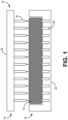
- FIG. 1 is a simplified cross-sectional illustration of tooling assembly 10 supporting preform 12.
- Tooling assembly 10 is more specifically a debulking tooling assembly used to shape/mold preform 12 while preform 12 is compressed by one or a combination of mechanical or vacuum pressure.
- Debulking helps reduce voids and remove gases within preform 12 and can be performed incrementally as layers are added to preform 12, and/or in a dedicated debulking step prior to matrix formation.
- Preform 12 can be formed from one or more layers of a ceramic (e.g., silicon carbide - SiC) fabric in a woven architecture such as plain, harness (e.g., 3, 5, 8, etc.), twill, braid, tape layup, or non-symmetric to name a few non-limiting examples.
- Non-woven architectures e.g., chopped, felted, etc.
- the fabric can be dry, stabilized, or a pre-preg material.
- tooling assembly 10 includes male (i.e., perforating) tooling fixture 14 and female (i.e., receiving) tooling fixture 16.
- Male tooling fixture 14 includes multiple pins 18 extending away from backplate 20.
- Pins 18 can be arranged as an array of rows and columns and can have uniform or varied lengths with respect to other pins 18, as is discussed below with respect to FIGS. 3A-3C .
- Pins 18 can be monolithically formed with, or removably attached to backplate 20 depending on the embodiment, as is discussed in greater detail below.
- Female tooling fixture 16 includes baseplate 22 with receiving holes 24 corresponding to respective pins 18 on male tooling fixture 14. Holes 24 can be sized to receive respective pins 18 when pins 18 are inserted through preform 12, as is shown in FIG. 2 .
- Tooling fixtures 14 and 16 can be formed from a metallic material, a hardened polymer (e.g., plastic), or ceramic, to name a few non-limiting examples.
- FIG. 2 is a simplified cross-sectional illustration of tooling assembly 10 in an assembled/engaged state around preform 12.
- fixtures 14 and 16 are configured to at least partially enclose preform 12 within fixed inner volume 26.
- fixtures 14 and 16 can be held together via clamps or other suitable means of securing one to the other.
- Pins 18 are inserted completely through the thickness of preform 12 such that the tips/ends extend partially into respective holes 24.
- z-channels will have been formed at the locations of each pin 18.
- a non-debulked or partially debulked preform 12 can be placed within tooling assembly 10, and a mechanical compressive force exerted on preform 12 as fixtures 14 and 16 are secured together. This can at least nominally reduce the thickness of preform 12.
- a vacuum can be generated within inner volume 26 to compress and debulk preform 12.
- a combination of mechanical and vacuum pressure can be used to debulk preform 12.
- z-channels are formed during debulking by pins 18. Pins 18 are inserted in such manner as to maximize the pushing away of individual fibers of perform 12, and to minimize the breaking of such fibers. Accordingly, formation of z-channels with pins 18 during debulking can be less destructive than methods such as laser drilling, as well as needling processes that occur in dedicated steps, requiring additional handling of preform 12.
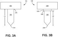
- FIG. 3A, 3B , and 3C are simplified side views of alternative male tooling fixtures 14A, 14B, and 14C respectively. More specifically, FIG. 3A shows an individual pin 18A extending from backplate 20A. Pin 18A has a length LA extending from base 28A to oppositely disposed tip 30A. Pin 18A is configured with a generally uniformly cylindrical portion over a majority of length LA and a relatively short taper near tip 30A such that tip 30A is pointed.
- tooling fixture 14A can be monolithically formed (e.g., additively manufactured, 3D printed, etc.) such that pins 18A and backplate 20A are formed from the same material (e.g., metal, polymer, etc.).
- Length LA can be uniform across all pins 18A in an exemplary embodiment.
- FIG. 3B shows individual pin 18B extending from mounting boss 32B on backplate 20B.
- pin 18B can be removably attached to backplate 20B via threaded or other engagement with mounting boss 32B.
- Base 28B can be defined as the portion of pin 18B immediately extending away from mounting boss 32B, although some of pin 18B can extend into mounting boss 32B.
- Pin 18B has an exposed length LB extending from base 28B to oppositely disposed tip 30B.
- LB can, in some embodiments, be less than LA due to the inclusion of mounting boss 32B, while in other embodiments, pin 18B can be elongated such that LB is generally equal to LA. Length LB can be uniform across all pins 18B in an exemplary embodiment.
- pin 18B can be mostly cylindrical with a short taper to form a point at tip 30B.
- Pin 18B can be formed from the same material as backplate 20B, or from a different material. For example, both can be formed from a hardened polymer material, or pin 18B can be formed from a hardened polymer or ceramic, while backplate 20B can be formed from metal.
- Removable pins 18B are individually replaceable in case of damage to certain pins 18B after repeated insertion into ceramic preform. Select pins 18B can also be removed to vary the pattern of pins 18B, for example by decreasing the total number of pins 18B to increase pin-to-pin spacing. In this manner, male tooling fixture 14B can be customizable on a per-preform basis.
- FIG. 3C shows multiple individual pins 18C of varied lengths, LC1, LC2, and LC3. More specifically, pins 18C are removably attached to backplate 20C via mounting bosses 32C, and the exposed length between base 28C and tip 30C of each pin 18C varies such that LC3 is greater than LC2, and LC2 is greater than LC1.
- Male tooling fixture 14C can be preferable where the thickness of preform 12 increases and/or decreases across a given preform area.
- FIG. 4 is a simplified cross-sectional view of alternative tooling assembly 110 for use with non-linear/non-planar preforms 112.
- Preform 112 can be substantially similar to preform 12, except that preform 112 is curved.
- preform 112 can be used to form an airfoil (e.g., for a blade or vane) of a gas turbine engine.
- tooling assembly 110 can be a debulking tooling assembly including male tooling fixture 114 and female tooling fixture 116, each having curvature corresponding to preform 112.
- Male tooling fixture 114 includes pins 118 extending from backplate 120.
- male tooling fixture 114 includes multiple smaller backplate sections 134, each with a subset of pins 118. As such, each section can be put into place and secured to adjacent sections for debulking, then individually removed. This permits pins 118 to be oriented generally normal to the surface of preform 112.
- Female tooling fixture 116 can include holes 124 corresponding to and configured to receive the tips of pins 118. In the embodiment shown, female tooling fixture can be a mandrel.
- Tooling assembly 110 operates substantially similarly to tooling assembly 10, applying a mechanical compressive force, and/or supporting preform 112 while a vacuum is applied.
- Tooling assembly 110 can be all or partially formed from metal, hardened polymer material, or ceramic.
- pins 118 can be monolithically formed with backplate 120 or removably attached thereto (e.g., via mounting bosses). Pins 118 can be the same material as backplate 120, or a different material. Pins 118 can further be mostly cylindrical with a short taper to form a pointed tip.
- preforms 12, 112 can be removed from respective tooling assemblies 10, 110 to undergo further processing.
- preforms 12, 112 can be transferred to graphite tooling assemblies for interface coating (IFC) deposition via CVI and/or densification (i.e., matrix formation) via CVI. Densification is carried out until the resulting CMC has reached the desired residual porosity.
- densification can include other methodologies such as, but not limited to, melt infiltration and polymer infiltration and pyrolysis (PIP).
- a CMC component formed with the disclosed tooling assemblies can be incorporated into aerospace, maritime, or industrial equipment, to name a few, non-limiting examples.
- a tooling assembly for debulking a fibrous preform includes a first tooling fixture comprising a plurality of receiving holes, and a second tooling fixture comprising a plurality of pins projecting toward the first tooling fixture, each of the plurality of pins corresponding to and extending towards one of the plurality of receiving holes.
- the second tooling fixture is engageable with the first tooling fixture to define an inner volume therebetween, the inner volume configured to support the preform during debulking while a compressive force is applied thereto.
- the tooling assembly of the preceding paragraph can optionally include, additionally and/or alternatively, any one or more of the following features, configurations and/or additional components:
- the second tooling fixture can be further engageable with the first tooling fixture such that the plurality of pins extend through the thickness of the preform and at least partially into respective ones of the plurality of receiving holes.
- a length of each of the plurality of pins can be uniform across the second tooling fixture.
- one pin of the plurality of pins can have a first length, and a second pin of the plurality of pins can have a second length greater than the first length.
- the second tooling fixture can further include a backplate.
- each of the plurality of pins can be removably attached to the backplate via a mounting boss.
- the plurality of pins can be monolithically formed with the backplate.
- the backplate can be formed from a first material
- the plurality of pins can be formed from a second material, the second material being different than the first material
- each of the backplate and the plurality of pins can be formed from the same material.
- the first tooling fixture and the backplate of the second tooling fixture can be curved.
- the backplate can include a plurality of sections, each of the plurality of sections including a subset of the plurality of pins.
- the first tooling fixture can be a mandrel.
- each of the plurality of pins can be cylindrical with a pointed tip.
- a method of preparing a fibrous preform for use in a ceramic matrix composite includes debulking the fibrous preform by supporting the preform with a first tooling fixture, the first tooling fixture including a plurality of receiving holes, engaging a second tooling fixture with the first tooling fixture such that the preform is disposed therebetween, and applying a compressive force to the preform.
- Engaging the second tooling fixture with the first tooling fixture causes a plurality of pins projecting from the first tooling fixture to extend through a thickness of the preform.
- engaging the second tooling fixture with the first tooling fixture can further cause the plurality of pins to extend at least partially into respective ones of the plurality of receiving holes.
- the compressive force can include one or a combination of mechanical pressure and vacuum pressure.
- debulking can further include after applying the compressive force to the preform, removing the second tooling fixture such that a plurality of z-channels is formed through the thickness of the preform.
- Any of the above methods can further include densifying the preform using one or a combination of chemical vapor infiltration, chemical vapor deposition, polymer infiltration and pyrolysis, and melt infiltration.
- the preform can be formed from silicon carbide.
- the first tooling fixture, the second tooling fixture, and the preform can be curved.
Landscapes
- Engineering & Computer Science (AREA)
- Chemical & Material Sciences (AREA)
- Ceramic Engineering (AREA)
- Manufacturing & Machinery (AREA)
- Structural Engineering (AREA)
- Materials Engineering (AREA)
- Organic Chemistry (AREA)
- Inorganic Chemistry (AREA)
- Chemical Kinetics & Catalysis (AREA)
- Life Sciences & Earth Sciences (AREA)
- Forests & Forestry (AREA)
- Mechanical Engineering (AREA)
- Textile Engineering (AREA)
- Moulding By Coating Moulds (AREA)
Abstract
Description
- The present invention relates to the fabrication of ceramic matrix composites (CMCs) and, more particularly, to CMCs having improved properties for operating in gas turbine engines.
- In the processing of CMCs, there is a need to infiltrate matrix within and around fibrous tows to replace pore volume with dense matrix material. In a woven system, large voids often exist between adjacent tows of a preform. Such voids can become large defects after infiltration of the composite that are detrimental to composite properties. The pore network through a woven system is often highly tortuous for infiltrating reactant vapors, which leads to uneven deposition through the thickness of the preform. The formation of z-channels can create more direct pathways for reactant gases, which can facilitate more even matrix infiltration. Thus, means for creating z-channels in preforms are desirable.
- A tooling assembly for debulking a fibrous preform includes a first tooling fixture comprising a plurality of receiving holes, and a second tooling fixture comprising a plurality of pins projecting toward the first tooling fixture, each of the plurality of pins corresponding to and extending towards one of the plurality of receiving holes. The second tooling fixture is engageable with the first tooling fixture to define an inner volume therebetween, the inner volume configured to support the preform during debulking while a compressive force is applied thereto.
- A method of preparing a fibrous preform for use in a ceramic matrix composite includes debulking the fibrous preform by supporting the preform with a first tooling fixture, the first tooling fixture including a plurality of receiving holes, engaging a second tooling fixture with the first tooling fixture such that the preform is disposed therebetween, and applying a compressive force to the preform. Engaging the second tooling fixture with the first tooling fixture causes a plurality of pins projecting from the first tooling fixture to extend through a thickness of the preform.
- Features of embodiments are set forth in the dependent claims.
-
-
FIG. 1 is a simplified cross-sectional illustration of a first embodiment of a preform tooling assembly with pins. -
FIG. 2 is a simplified cross-sectional illustration of the preform tooling assembly ofFIG. 1 in an assembled state such that the pins are inserted through the preform. -
FIGS. 3A, 3B , and3C are simplified side views of portions of alternative male tooling fixtures for the tooling assemblies ofFIGS. 1 and2 . -
FIG. 4 is a simplified cross-sectional illustration of a second embodiment of a preform tooling assembly with pins. - While the above-identified figures set forth one or more embodiments of the present disclosure, other embodiments are also contemplated, as noted in the discussion. In all cases, this disclosure presents the invention by way of representation and not limitation. It should be understood that numerous other modifications and embodiments can be devised by those skilled in the art, which fall within the scope and spirit of the principles of the invention. The figures may not be drawn to scale, and applications and embodiments of the present invention may include features and components not specifically shown in the drawings.
- This disclosure presents means for perforating a fibrous ceramic preform prior to densification (e.g., via chemical vapor infiltration - CVI). More specifically, perforation can be performed during a debulking process. Multiple embodiments of combined perforating/debulking tooling can be used to create z-channels through the thickness of the preform, such that separate tooling is advantageously not required. Z-channels facilitate access to the interior of the preform by reactant vapors such that matrix deposits in a more even manner compared to non-perforated preforms.
-
FIG. 1 is a simplified cross-sectional illustration oftooling assembly 10 supportingpreform 12.Tooling assembly 10 is more specifically a debulking tooling assembly used to shape/mold preform 12 while preform 12 is compressed by one or a combination of mechanical or vacuum pressure. Debulking helps reduce voids and remove gases withinpreform 12 and can be performed incrementally as layers are added to preform 12, and/or in a dedicated debulking step prior to matrix formation. Preform 12 can be formed from one or more layers of a ceramic (e.g., silicon carbide - SiC) fabric in a woven architecture such as plain, harness (e.g., 3, 5, 8, etc.), twill, braid, tape layup, or non-symmetric to name a few non-limiting examples. Non-woven architectures (e.g., chopped, felted, etc.) are also contemplated herein. The fabric can be dry, stabilized, or a pre-preg material. - As shown,
tooling assembly 10 includes male (i.e., perforating)tooling fixture 14 and female (i.e., receiving)tooling fixture 16.Male tooling fixture 14 includesmultiple pins 18 extending away frombackplate 20.Pins 18 can be arranged as an array of rows and columns and can have uniform or varied lengths with respect toother pins 18, as is discussed below with respect toFIGS. 3A-3C .Pins 18 can be monolithically formed with, or removably attached tobackplate 20 depending on the embodiment, as is discussed in greater detail below.Female tooling fixture 16 includesbaseplate 22 with receivingholes 24 corresponding torespective pins 18 onmale tooling fixture 14.Holes 24 can be sized to receiverespective pins 18 whenpins 18 are inserted throughpreform 12, as is shown inFIG. 2 .Tooling fixtures -
FIG. 2 is a simplified cross-sectional illustration oftooling assembly 10 in an assembled/engaged state around preform 12. In the assembled state,fixtures inner volume 26. Although not shown inFIG. 2 ,fixtures Pins 18 are inserted completely through the thickness ofpreform 12 such that the tips/ends extend partially intorespective holes 24. Whenmale tooling fixture 14 andpins 18 are removed from preform 12, z-channels will have been formed at the locations of eachpin 18. - In one example, a non-debulked or partially debulked
preform 12 can be placed withintooling assembly 10, and a mechanical compressive force exerted onpreform 12 asfixtures preform 12. In another example, a vacuum can be generated withininner volume 26 to compress and debulk preform 12. In yet another example, a combination of mechanical and vacuum pressure can be used to debulk preform 12. In any case, z-channels are formed during debulking bypins 18.Pins 18 are inserted in such manner as to maximize the pushing away of individual fibers of perform 12, and to minimize the breaking of such fibers. Accordingly, formation of z-channels withpins 18 during debulking can be less destructive than methods such as laser drilling, as well as needling processes that occur in dedicated steps, requiring additional handling of preform 12. -
FIG. 3A, 3B , and3C are simplified side views of alternativemale tooling fixtures FIG. 3A shows anindividual pin 18A extending frombackplate 20A.Pin 18A has a length LA extending frombase 28A to oppositely disposedtip 30A. Pin 18A is configured with a generally uniformly cylindrical portion over a majority of length LA and a relatively short taper neartip 30A such thattip 30A is pointed. In the embodiment shown,tooling fixture 14A can be monolithically formed (e.g., additively manufactured, 3D printed, etc.) such thatpins 18A andbackplate 20A are formed from the same material (e.g., metal, polymer, etc.). Length LA can be uniform across allpins 18A in an exemplary embodiment. -
FIG. 3B showsindividual pin 18B extending from mountingboss 32B onbackplate 20B. As such,pin 18B can be removably attached to backplate 20B via threaded or other engagement with mountingboss 32B.Base 28B can be defined as the portion ofpin 18B immediately extending away from mountingboss 32B, although some ofpin 18B can extend into mountingboss 32B.Pin 18B has an exposed length LB extending frombase 28B to oppositely disposedtip 30B. LB can, in some embodiments, be less than LA due to the inclusion of mountingboss 32B, while in other embodiments, pin 18B can be elongated such that LB is generally equal to LA. Length LB can be uniform across allpins 18B in an exemplary embodiment. Likepin 18A, pin 18B can be mostly cylindrical with a short taper to form a point attip 30B.Pin 18B can be formed from the same material as backplate 20B, or from a different material. For example, both can be formed from a hardened polymer material, or pin 18B can be formed from a hardened polymer or ceramic, whilebackplate 20B can be formed from metal.Removable pins 18B are individually replaceable in case of damage tocertain pins 18B after repeated insertion into ceramic preform.Select pins 18B can also be removed to vary the pattern ofpins 18B, for example by decreasing the total number ofpins 18B to increase pin-to-pin spacing. In this manner,male tooling fixture 14B can be customizable on a per-preform basis. -
FIG. 3C shows multipleindividual pins 18C of varied lengths, LC1, LC2, and LC3. More specifically, pins 18C are removably attached to backplate 20C via mountingbosses 32C, and the exposed length betweenbase 28C andtip 30C of eachpin 18C varies such that LC3 is greater than LC2, and LC2 is greater than LC1.Male tooling fixture 14C can be preferable where the thickness ofpreform 12 increases and/or decreases across a given preform area. -
FIG. 4 is a simplified cross-sectional view ofalternative tooling assembly 110 for use with non-linear/non-planar preforms 112. Preform 112 can be substantially similar to preform 12, except thatpreform 112 is curved. In one embodiment, preform 112 can be used to form an airfoil (e.g., for a blade or vane) of a gas turbine engine. Like toolingassembly 10,tooling assembly 110 can be a debulking tooling assembly includingmale tooling fixture 114 andfemale tooling fixture 116, each having curvature corresponding to preform 112.Male tooling fixture 114 includespins 118 extending frombackplate 120. To facilitate insertion and removal ofpins 118 into/frompreform 112,male tooling fixture 114 includes multiplesmaller backplate sections 134, each with a subset ofpins 118. As such, each section can be put into place and secured to adjacent sections for debulking, then individually removed. This permits pins 118 to be oriented generally normal to the surface ofpreform 112.Female tooling fixture 116 can includeholes 124 corresponding to and configured to receive the tips ofpins 118. In the embodiment shown, female tooling fixture can be a mandrel. -
Tooling assembly 110 operates substantially similarly totooling assembly 10, applying a mechanical compressive force, and/or supportingpreform 112 while a vacuum is applied.Tooling assembly 110 can be all or partially formed from metal, hardened polymer material, or ceramic. Likepins backplate 120 or removably attached thereto (e.g., via mounting bosses).Pins 118 can be the same material asbackplate 120, or a different material.Pins 118 can further be mostly cylindrical with a short taper to form a pointed tip. - After debulking, preforms 12, 112 can be removed from
respective tooling assemblies - A CMC component formed with the disclosed tooling assemblies can be incorporated into aerospace, maritime, or industrial equipment, to name a few, non-limiting examples.
- The following are non-exclusive descriptions of possible embodiments of the present invention.
- A tooling assembly for debulking a fibrous preform includes a first tooling fixture comprising a plurality of receiving holes, and a second tooling fixture comprising a plurality of pins projecting toward the first tooling fixture, each of the plurality of pins corresponding to and extending towards one of the plurality of receiving holes. The second tooling fixture is engageable with the first tooling fixture to define an inner volume therebetween, the inner volume configured to support the preform during debulking while a compressive force is applied thereto.
- The tooling assembly of the preceding paragraph can optionally include, additionally and/or alternatively, any one or more of the following features, configurations and/or additional components:
In the above tooling assembly, the second tooling fixture can be further engageable with the first tooling fixture such that the plurality of pins extend through the thickness of the preform and at least partially into respective ones of the plurality of receiving holes. - In any of the above tooling assemblies, a length of each of the plurality of pins can be uniform across the second tooling fixture.
- In any of the above tooling assemblies, one pin of the plurality of pins can have a first length, and a second pin of the plurality of pins can have a second length greater than the first length.
- In any of the above tooling assemblies, the second tooling fixture can further include a backplate.
- In any of the above tooling assemblies, each of the plurality of pins can be removably attached to the backplate via a mounting boss.
- In any of the above tooling assemblies, the plurality of pins can be monolithically formed with the backplate.
- In any of the above tooling assemblies, the backplate can be formed from a first material, and the plurality of pins can be formed from a second material, the second material being different than the first material.
- In any of the above tooling assemblies, each of the backplate and the plurality of pins can be formed from the same material.
- In any of the above tooling assemblies, the first tooling fixture and the backplate of the second tooling fixture can be curved.
- In any of the above tooling assemblies, the backplate can include a plurality of sections, each of the plurality of sections including a subset of the plurality of pins.
- In any of the above tooling assemblies, the first tooling fixture can be a mandrel.
- In any of the above tooling assemblies, each of the plurality of pins can be cylindrical with a pointed tip.
- A method of preparing a fibrous preform for use in a ceramic matrix composite includes debulking the fibrous preform by supporting the preform with a first tooling fixture, the first tooling fixture including a plurality of receiving holes, engaging a second tooling fixture with the first tooling fixture such that the preform is disposed therebetween, and applying a compressive force to the preform. Engaging the second tooling fixture with the first tooling fixture causes a plurality of pins projecting from the first tooling fixture to extend through a thickness of the preform.
- The method of the preceding paragraph can optionally include, additionally and/or alternatively, any one or more of the following features, configurations and/or additional components:
In the above method, engaging the second tooling fixture with the first tooling fixture can further cause the plurality of pins to extend at least partially into respective ones of the plurality of receiving holes. - In any of the above methods, the compressive force can include one or a combination of mechanical pressure and vacuum pressure.
- In any of the above methods, debulking can further include after applying the compressive force to the preform, removing the second tooling fixture such that a plurality of z-channels is formed through the thickness of the preform.
- Any of the above methods can further include densifying the preform using one or a combination of chemical vapor infiltration, chemical vapor deposition, polymer infiltration and pyrolysis, and melt infiltration.
- In any of the above methods, the preform can be formed from silicon carbide.
- In any of the above methods, the first tooling fixture, the second tooling fixture, and the preform can be curved.
- While the invention has been described with reference to an exemplary embodiment(s), it will be understood by those skilled in the art that various changes may be made and equivalents may be substituted for elements thereof without departing from the scope of the invention. In addition, many modifications may be made to adapt a particular situation or material to the teachings of the invention without departing from the essential scope thereof. Therefore, it is intended that the invention not be limited to the particular embodiment(s) disclosed, but that the invention will include all embodiments falling within the scope of the appended claims.
Claims (15)
- A tooling assembly (10; 110) for debulking a fibrous preform (12; 112), the tooling assembly comprising:a first tooling fixture (16; 116) comprising a plurality of receiving holes (24; 124); anda second tooling fixture (14; 14A; 14B; 14C; 114) comprising a plurality of pins (18; 18A; 18B; 18C; 118) projecting toward the first tooling fixture (16; 116), each of the plurality of pins (18; 18A; 18B; 18C; 118) corresponding to and extending towards one of the plurality of receiving holes (24; 124),wherein the second tooling fixture (14; 14A; 14B; 14C; 114) is engageable with the first tooling fixture (16; 116) to define an inner volume (26) therebetween, the inner volume (26) configured to support the preform (12; 112) during debulking while a compressive force is applied thereto.
- The tooling assembly of claim 1, wherein the second tooling fixture (14; 14A; 14B; 14C; 114) is further engageable with the first tooling fixture (16; 116) such that the plurality of pins (18; 18A; 18B; 18C; 118) extend through the thickness of the preform (12; 112) and at least partially into respective ones of the plurality of receiving holes (24; 124).
- The tooling assembly of claim 1 or 2, wherein a length (LA; LB) of each of the plurality of pins (18; 18A; 18B; 118) is uniform across the second tooling fixture (14; 14A; 14B; 114).
- The tooling assembly of claim 1 or 2, wherein one pin (18C) of the plurality of pins (18C) has a first length (LC1; LC2), and wherein a second pin (18C) of the plurality of pins (18C) has a second length (LC2; LC3) greater than the first length (LC1; LC2).
- The tooling assembly of any preceding claim, wherein the second tooling fixture (14; 14A; 14B; 14C; 114) further comprises a backplate (20; 20A; 20B; 20C; 120).
- The tooling assembly of claim 5, wherein each of the plurality of pins (18B; 18C) is removably attached to the backplate (20B; 20C) via a mounting boss (32B; 32C), or wherein the plurality of pins (18A) are monolithically formed with the backplate (20A).
- The tooling assembly of claim 5 or 6, wherein the backplate (20; 20A; 20B; 20C; 120) is formed from a first material, and wherein the plurality of pins (18; 18A; 18B; 18C; 118) are formed from a second material, the second material being different than the first material, or wherein each of the backplate (20; 20A; 20B; 20C; 120) and the plurality of pins (18; 18A; 18B; 18C; 118) are formed from the same material.
- The tooling assembly of claim 5, 6 or 7, wherein the first tooling fixture (116) and the backplate (120) of the second tooling fixture (114) are curved.
- The tooling assembly of any of claim 8, wherein the backplate (120) comprises a plurality of sections (134), each of the plurality of sections (134) comprising a subset of the plurality of pins (118).
- The tooling assembly of claim 8 or 9, wherein the first tooling fixture (116) is a mandrel.
- The tooling assembly of any preceding claim, wherein each of the plurality of pins (18; 18A; 18B; 18C) is cylindrical with a pointed tip (30A; 30B; 30C).
- A method of preparing a fibrous preform (12; 112) for use in a ceramic matrix composite, the method comprising:
debulking the fibrous preform (12; 112) by:supporting the preform (12; 112) with a first tooling fixture (16; 116), the first tooling fixture (16; 116) comprising a plurality of receiving holes (24; 124);engaging a second tooling fixture (14; 14A; 14B; 14C; 114) with the first tooling fixture (16; 116) such that the preform (12; 112) is disposed therebetween; andapplying a compressive force to the preform (12; 112),wherein engaging the second tooling fixture (14; 14A; 14B; 14C; 114) with the first tooling fixture (16; 116) causes a plurality of pins (18; 18A; 18B; 18C; 118) projecting from the second tooling fixture (14; 14A; 14B; 14C; 114) to extend through a thickness of the preform (12; 112). - The method of claim 12, wherein engaging the second tooling fixture (14; 14A; 14B; 14C; 114) with the first tooling fixture (16; 116) further causes the plurality of pins (18; 18A; 18B; 18C; 118) to extend at least partially into respective ones of the plurality of receiving holes (24; 124); and/or wherein the compressive force comprises one or a combination of mechanical pressure and vacuum pressure.
- The method of claim 12 or 13, wherein debulking further comprises: after applying the compressive force to the preform (12; 112), removing the second tooling fixture (14; 14A; 14B; 14C; 114) such that a plurality of z-channels is formed through the thickness of the preform (12; 112), optionally wherein the method further comprises: densifying the preform (12; 112) using one or a combination of chemical vapor infiltration, chemical vapor deposition, polymer infiltration and pyrolysis, and melt infiltration.
- The method of any of claims 12 to 14, wherein the preform (12; 112) is formed from silicon carbide; and/or wherein the first tooling fixture (116), the second tooling fixture (114), and the preform (112) are curved.
Applications Claiming Priority (1)
| Application Number | Priority Date | Filing Date | Title |
|---|---|---|---|
| US18/134,941 US20240344255A1 (en) | 2023-04-14 | 2023-04-14 | Z-channel creation in woven preform by incorporation of pin features into preform tooling |
Publications (1)
| Publication Number | Publication Date |
|---|---|
| EP4454842A1 true EP4454842A1 (en) | 2024-10-30 |
Family
ID=90720538
Family Applications (1)
| Application Number | Title | Priority Date | Filing Date |
|---|---|---|---|
| EP24170016.0A Pending EP4454842A1 (en) | 2023-04-14 | 2024-04-12 | Z-channel creation in woven preform by incorporation of pin features into preform tooling |
Country Status (2)
| Country | Link |
|---|---|
| US (1) | US20240344255A1 (en) |
| EP (1) | EP4454842A1 (en) |
Families Citing this family (2)
| Publication number | Priority date | Publication date | Assignee | Title |
|---|---|---|---|---|
| US12552085B2 (en) | 2023-10-20 | 2026-02-17 | Rtx Corporation | Z-channeling into a preform via needle perforation in a stand-alone tool |
| US12473236B2 (en) * | 2023-10-20 | 2025-11-18 | Rtx Corporation | Internal tooling configuration for the creation of z-channels in woven ceramic matrix composite preforms |
Citations (3)
| Publication number | Priority date | Publication date | Assignee | Title |
|---|---|---|---|---|
| WO1997031772A1 (en) * | 1996-02-27 | 1997-09-04 | Sumitomo Chemical Company, Limited | Method of manufacturing composite |
| CN108215246A (en) * | 2018-03-09 | 2018-06-29 | 湖南航天环宇通信科技股份有限公司 | The forming frock and its application method of porous multiple material product |
| EP4344843A1 (en) * | 2022-09-30 | 2024-04-03 | RTX Corporation | Spiked preform tooling for improved chemical vapor infiltration in ceramic matrix composites |
Family Cites Families (11)
| Publication number | Priority date | Publication date | Assignee | Title |
|---|---|---|---|---|
| US2289177A (en) * | 1939-02-09 | 1942-07-07 | Perfotex Company | Composite foraminous material |
| US2611434A (en) * | 1948-01-12 | 1952-09-23 | Charles M Mugler | Coring or perforating device |
| US4486372A (en) * | 1983-09-30 | 1984-12-04 | Rohr Industries, Inc. | Method for fabricating contoured perforated composite laminate structure |
| US5066442A (en) * | 1989-02-28 | 1991-11-19 | Massachusetts Institute Of Technology | Method of producing a composite article |
| US5246520A (en) * | 1991-02-12 | 1993-09-21 | Auto-Air Composites, Inc. | One step molded continuous fiber reinforced perforated composite panels |
| IT1260632B (en) * | 1993-03-29 | 1996-04-22 | Sepi Spa | PROCESS AND EQUIPMENT FOR THE MANUFACTURE OF A PADDED ELEMENT, IN PARTICULAR FOR A VEHICLE SEAT. |
| US5515585A (en) * | 1994-07-25 | 1996-05-14 | The Bf Goodrich Company | Process for forming needled fibrous structures using determined transport depth |
| US6190602B1 (en) * | 1998-03-13 | 2001-02-20 | Aztex, Inc. | Method of manufacturing a perforated laminate |
| US6203738B1 (en) * | 1999-03-29 | 2001-03-20 | Masonite Corporation | Method for providing more uniform density in the manufacture of lightweight structural fiberboard panels |
| US8128775B2 (en) * | 2008-12-30 | 2012-03-06 | Mra Systems, Inc. | Process and apparatus for producing composite structures |
| US10005246B2 (en) * | 2013-08-22 | 2018-06-26 | Faurecia Interior Systems, Inc. | Methods for making interior panels for motor vehicles |
-
2023
- 2023-04-14 US US18/134,941 patent/US20240344255A1/en not_active Abandoned
-
2024
- 2024-04-12 EP EP24170016.0A patent/EP4454842A1/en active Pending
Patent Citations (3)
| Publication number | Priority date | Publication date | Assignee | Title |
|---|---|---|---|---|
| WO1997031772A1 (en) * | 1996-02-27 | 1997-09-04 | Sumitomo Chemical Company, Limited | Method of manufacturing composite |
| CN108215246A (en) * | 2018-03-09 | 2018-06-29 | 湖南航天环宇通信科技股份有限公司 | The forming frock and its application method of porous multiple material product |
| EP4344843A1 (en) * | 2022-09-30 | 2024-04-03 | RTX Corporation | Spiked preform tooling for improved chemical vapor infiltration in ceramic matrix composites |
Also Published As
| Publication number | Publication date |
|---|---|
| US20240344255A1 (en) | 2024-10-17 |
Similar Documents
| Publication | Publication Date | Title |
|---|---|---|
| EP4454842A1 (en) | Z-channel creation in woven preform by incorporation of pin features into preform tooling | |
| US8057880B2 (en) | Non-oxide selectively porous materials | |
| EP1122052A2 (en) | Manufacturing method and apparatus of fiber reinforced composite member | |
| EP4344843A1 (en) | Spiked preform tooling for improved chemical vapor infiltration in ceramic matrix composites | |
| US12545628B2 (en) | Sheathed metallic needles for producing z-channels in fibrous preforms | |
| EP4446076A1 (en) | A method of forming a ceramic matrix composite, and a pin array | |
| EP4434701B1 (en) | Tooling for producing z-channels in ceramic fiber preforms | |
| US12528228B2 (en) | Methods for complex geometry mandrel removal of ceramic matrix composite components | |
| EP4541535A1 (en) | Z-channeling into a preform via needle perforation in a stand-alone tool | |
| EP3502307B1 (en) | Method of increasing the uniformity of chemical vapor deposition on fibrous material through the imposition of pressure waves | |
| EP4286127B1 (en) | A fibrous preform comprising a plurality of hourglass-shaped voids | |
| CN111315711A (en) | Method of manufacturing parts made of CMC | |
| JP4446135B2 (en) | Method and apparatus for manufacturing fiber reinforced composite member | |
| EP4357114A1 (en) | Floating tooling assembly for chemical vapor infiltration | |
| EP4470740A1 (en) | Additively manufactured graphite tooling | |
| EP4431483A1 (en) | Three dimensional weave with sacrifical z-fibers for improved ceramic matrix composite microstructure | |
| US12473236B2 (en) | Internal tooling configuration for the creation of z-channels in woven ceramic matrix composite preforms | |
| US12565451B2 (en) | Multi-mandrel braiding process | |
| US12435008B2 (en) | Auxetic materials and structures for ceramic matrix composite airfoil mandrels | |
| EP4345188A1 (en) | Ceramic matrix composite tooling for chemical vapor infiltration process | |
| JP3128571B2 (en) | Method of manufacturing C / C composite product |
Legal Events
| Date | Code | Title | Description |
|---|---|---|---|
| PUAI | Public reference made under article 153(3) epc to a published international application that has entered the european phase |
Free format text: ORIGINAL CODE: 0009012 |
|
| STAA | Information on the status of an ep patent application or granted ep patent |
Free format text: STATUS: THE APPLICATION HAS BEEN PUBLISHED |
|
| AK | Designated contracting states |
Kind code of ref document: A1 Designated state(s): AL AT BE BG CH CY CZ DE DK EE ES FI FR GB GR HR HU IE IS IT LI LT LU LV MC ME MK MT NL NO PL PT RO RS SE SI SK SM TR |
|
| STAA | Information on the status of an ep patent application or granted ep patent |
Free format text: STATUS: REQUEST FOR EXAMINATION WAS MADE |
|
| 17P | Request for examination filed |
Effective date: 20250425 |
|
| STAA | Information on the status of an ep patent application or granted ep patent |
Free format text: STATUS: EXAMINATION IS IN PROGRESS |
|
| 17Q | First examination report despatched |
Effective date: 20250924 |