EP4454824A1 - Lighting module for a handheld power tool, power module, lighting assembly, handheld power tool, and method for mounting a lighting module on a handheld power tool - Google Patents
Lighting module for a handheld power tool, power module, lighting assembly, handheld power tool, and method for mounting a lighting module on a handheld power tool Download PDFInfo
- Publication number
- EP4454824A1 EP4454824A1 EP23170596.3A EP23170596A EP4454824A1 EP 4454824 A1 EP4454824 A1 EP 4454824A1 EP 23170596 A EP23170596 A EP 23170596A EP 4454824 A1 EP4454824 A1 EP 4454824A1
- Authority
- EP
- European Patent Office
- Prior art keywords
- lighting module
- module
- tool
- main body
- power tool
- Prior art date
- Legal status (The legal status is an assumption and is not a legal conclusion. Google has not performed a legal analysis and makes no representation as to the accuracy of the status listed.)
- Pending
Links
Images

Classifications
-
- B—PERFORMING OPERATIONS; TRANSPORTING
- B25—HAND TOOLS; PORTABLE POWER-DRIVEN TOOLS; MANIPULATORS
- B25F—COMBINATION OR MULTI-PURPOSE TOOLS NOT OTHERWISE PROVIDED FOR; DETAILS OR COMPONENTS OF PORTABLE POWER-DRIVEN TOOLS NOT PARTICULARLY RELATED TO THE OPERATIONS PERFORMED AND NOT OTHERWISE PROVIDED FOR
- B25F5/00—Details or components of portable power-driven tools not particularly related to the operations performed and not otherwise provided for
- B25F5/02—Construction of casings, bodies or handles
- B25F5/021—Construction of casings, bodies or handles with guiding devices
-
- B—PERFORMING OPERATIONS; TRANSPORTING
- B25—HAND TOOLS; PORTABLE POWER-DRIVEN TOOLS; MANIPULATORS
- B25H—WORKSHOP EQUIPMENT, e.g. FOR MARKING-OUT WORK; STORAGE MEANS FOR WORKSHOPS
- B25H1/00—Work benches; Portable stands or supports for positioning portable tools or work to be operated on thereby
- B25H1/0021—Stands, supports or guiding devices for positioning portable tools or for securing them to the work
- B25H1/0078—Guiding devices for hand tools
- B25H1/0092—Guiding devices for hand tools by optical means
Definitions
- the present invention relates to a lighting module for a handheld power tool having a tool component.
- the present invention is further directed to a power module for supplying electricity to a lighting module for a handheld power tool.
- the present invention additionally relates to a lighting assembly for a handheld power tool.
- the present invention is directed to a handheld power tool and a method for mounting a lighting module on a handheld power tool.
- the tool component is configured for interacting with a workpiece in order to perform a desired manufacturing step thereon, e.g. modify the outer shape of the workpiece.
- a desired manufacturing step e.g. modify the outer shape of the workpiece.
- various examples of illumination devices have been disclosed.
- a lighting module for a handheld power tool having a tool component.
- the lighting module comprises a ring-shaped main body forming a workspace configured for enabling an operation of the tool component of the handheld power tool in the workspace.
- the main body is at least partially transparent or translucent.
- At least one light source is disposed on the main body, wherein the at least one light source is configured for illuminating the workspace.
- the main body is ring-shaped and the main body creates a workspace for the tool component and the at least one light source disposed on the main body, the light source is positionable very close to the tool component and the portion of a workpiece interacting with the tool component. This enhances the visibility of both the tool component and the portion of the workpiece.
- the ring-shaped main body extends at least partially around the tool component such that the tool component and a portion of the workpiece is capable of being illuminated in a direct manner.
- the main body is at least partially transparent or translucent, the main body reduces the obstruction of the illumination to a considerable extent.
- the main body is transparent, the user of the handheld power tool whereto the lighting module is connected, would be in a position to even see through the main body. This further enhances the visibility of the tool component and the portion of the workpiece interacting with the tool component. Therewith, an extent of illumination is considerably enhanceable.
- a shape of the light source is variable and is designable based on at least one of the application and structure of the power tool, the workpiece, the workspace, et cetera.
- the light source is point-shaped.
- Such a light source is structurally simple and very compact. Thus, it does not hinder the tool component and/or the portion of the workpiece interacting with the tool component.
- a lighting module comprising such a light source is designable in a very compact manner.
- the light source is line-shaped, and the light source extends substantially along one dimension. According to one aspect, this direction corresponds to a circumferential direction of the main body and/or the workspace.
- the tool component and the portion of the workpiece interacting with the tool component is capable of being illuminated from different angles or sides using a single light source.
- a light source is compact, at least in a direction perpendicular to its direction of extension.
- the light source is a surface light source, whereby the light source extends substantially in two dimensions. The extension of the light source in these two dimensions is substantially equal or different.
- the tool component and the workpiece portion interacting with the tool component is capable of being illuminated from multiple angles or sides, whereby enhancing the quality of illumination.
- the lighting module comprises at least two light sources.
- the two light sources are disposed at different locations on the main body.
- the shape of each of the light sources is variable in accordance with one or more of the examples as mentioned above.
- the two light sources are arrangeable in accordance with a regular pattern. However, this need not be the case always.
- the tool component and a portion of the workpiece interacting with the tool component may be illuminated from at least two sides or angles. This avoids the creation of shadows and enhances visibility of the tool component and the portion of the workpiece interacting with the tool component.
- the lighting module for example comprises two to thirty light sources, preferably two to twenty light sources. In more specific examples, the lighting module comprises 2, 3, 4, 5, 6, 8, 10 or 12 light sources.
- each of the one or more light sources may comprise one or more light emitting diodes (LEDs). Using LEDs, an energy-efficient illumination is achievable.
- the main body is transparent. Consequently, a user of the handheld power tool would be able to see through any portion of the main body.
- the main body in its entirety does not obstruct a view of the tool component and/or on the portion of the workpiece interacting with the tool component.
- ring-shaped comprises both fully closed ring shapes and partially closed ring shapes.
- a main body being shaped as a partially closed ring may for example circumferentially enclose the workspace by 90 degrees to 355 degrees.
- the main body being shaped as a partially closed ring may circumferentially enclose the workspace by 180 degrees to 355 degrees.
- the main body being shaped as a partially closed ring may circumferentially enclose the workspace by 270 degrees to 355 degrees.
- “circumferentially enclosing” means extending along a circumference of the workspace.
- the workspace may also be called a "reception channel" for the tool component.
- the main body is designed for creating a workspace having a circular, elliptical or polygonal cross section.
- the shape of the main body may resemble a fully or partially closed ring.
- the main body has the form of a fully closed, circular, elliptical or polygonal ring.
- the main body is shaped like a partially closed ring. Consequently, the main body is shaped as a portion of a circle, a portion of an ellipse or a portion of a polygon.
- An example of a polygon is a quadrangle, such as a rectangle.
- the shape of the main body is chosen such that it fits a handheld power tool to which the lighting module is connected. This allows to reliably illuminate the tool component and a portion of the workpiece interacting with the tool component.
- the main body circumferentially fully encloses the workspace.
- the main body is shaped as a fully closed ring. It is noted that this does not exclude that a height or a thickness of the main body varies along its circumference.
- the main body offers the possibility to locate a light source at any desired circumferential position. This allows the light sources to be arranged in a manner that avoids shadows and other undesired optical effects. Moreover, such a main body is mechanically stable.
- the lighting module may comprise at least two light sources which are arranged equidistantly along the perimeter of the main body.
- the at least two light sources are also arranged equidistantly along the perimeter of the workspace. This means that all circumferential distances between the at least two light sources are the same. This allows for a uniform illumination of the tool component and the portion of the workpiece interacting with the tool component. At the same time, undesired optical effects such as shadows are reduceable.
- the lighting module may further comprise a mechanical power tool connection interface configured for mechanically connecting the lighting module to the handheld power tool.
- a mechanical power tool connection interface configured for mechanically connecting the lighting module to the handheld power tool.
- the lighting module further comprises a mechanical power module connection interface configured for mechanically connecting the lighting module to a power module.
- the power module is configured for providing electric power to the lighting module. Consequently, the lighting module and the power module is reliably connected. It is understood that a mechanical power module connection interface is only necessary, if the lighting module and the power module are separate from one another.
- the mechanical power module connection interface may be configured as a releasable power module connection interface. Consequently, the lighting module and the power module become selectively separable and selectively connectable.
- the mechanical power module connection interface comprises a connection protrusion configured for being received in a connection recess of the power module.
- the mechanical power module connection interface comprises a connection recess being configured for receiving a connection protrusion of the power module.
- the connection protrusion of the mechanical power module connection interface or the connection recess of the mechanical power module connection interface may have the form of a dove tail.
- a dovetail shaped connection is both structurally simple and mechanically stable. Moreover, such a connection is easily establishable and releasable by a user of the lighting module or the handheld power tool.
- the lighting module may further comprise an electric power connection interface.
- the electric power connection interface is configured for electrically connecting the lighting module to an electric power source.
- the electric power connection interface may be electrically connected to the at least one light source. As a result thereof, electric power is reliably provided to the light sources.
- the electric power connection interface is configured for being electrically connected to a power module.
- the electric power connection interface is configured for being electrically connected to a power source of the handheld power tool, e.g. a power source, such as a power tool battery pack, that is also used for providing electric power to a drive unit being configured for operating the tool component.
- the main body comprises a particle guiding surface.
- the particle guiding surface is oriented towards the workspace.
- a particle is to be understood as a particle of the workpiece, i.e. a workpiece particle such as dust, chips, splinters, shavings, et cetera. This means that the particle is always made of the same material as the workpiece.
- the lighting module not only provides the functionality of illuminating the tool component and the workpiece portion interacting there with, but also a functionality for guiding particles to be removed and/or redirected away from the workspace for enhancing the cleanliness of the workspace.
- the main body forms a part of a particle extraction hood.
- the main body is used for eliminating particles from a region in which the tool component and the portion of the workpiece interact. Removing particles further enhances the visibility of the tool component and the portion of the workpiece interacting therewith. Additionally, providing both the functionality of illuminating and the functionality of guiding particles by one module, i.e. the lighting module, is structurally simple, compact and cost-efficient.
- the lighting module comprising the particle guiding surface may alternatively be considered as a particle guiding element.
- the particle guiding element comprises a ring-shaped main body forming a workspace configured for enabling an operation of the tool component of the handheld power tool in the workspace.
- the main body may be at least partially transparent or translucent.
- the particle guiding element may additionally comprise at least one light source disposed on the main body, wherein the at least one light source is configured for illuminating the workspace.
- the lighting module according to the invention may as well be called a particle guiding element.
- a power module for supplying electricity to a lighting module for a handheld power tool.
- the power module comprises a battery unit, an electric connection interface and a mechanical connection interface.
- the electric connection interface is configured for electrically connecting to the lighting module.
- the electric connection interface is electrically connected to the battery unit.
- the mechanical connection interface is configured for mechanically connecting to the lighting module.
- the lighting module may be a lighting module according to the invention. Such a power module allows to supply electricity or electric power to the lighting module independent from the type or configuration of a handheld power tool to which the lighting module and/or the power module is connected.
- a lighting module may be retrofitted to a handheld power tool which is not specifically adapted to the use of a lighting module.
- a possibility to retrofit the lighting module to the handheld power tool makes the lighting module backward-compatible.
- the battery unit of the power module may be configured as a rechargeable battery unit. Additionally and/or alternatively, the battery unit may be releasably connected to the remaining components of the power module.
- a lighting assembly for a handheld power tool.
- the lighting assembly comprises a lighting module according to the invention and a power module according to the invention.
- the lighting module and the power module are mechanically and electrically connected.
- the lighting module and the power module may be connected in a releasable manner. This may apply to both the mechanical and the electrical connection. If the lighting module and the power module are releasably connected, the lighting module and the power module may be easily disconnected, e.g. for changing the power module in case of an empty battery unit.
- the lighting assembly may be used in combination with a great variety of different handheld power tools since the supply of electric energy may be independent from the type or configuration of a handheld power tool. Moreover, such a lighting assembly is structurally simple and compact.
- a handheld power tool comprising a movable tool component for interacting with a workpiece.
- the handheld power tool comprises a base plate having a contact surface for positioning the handheld power tool on the workpiece.
- An opening is provided in the base plate and the tool component extends through the opening, especially during an operation of the handheld power tool on the workpiece.
- a lighting module according to the invention is arranged on the base plate and the workspace is positioned coaxially to the opening.
- the lighting module is arranged on the handheld power tool such that the main body of the lighting module fully or partially extends around a circumference of the opening in the base plate.
- the lighting module is at least partially arranged in the opening.
- the lighting module may illuminate the tool component and the portion of the workpiece interacting with the tool component in a reliable manner. It is understood that the tool component may permanently or temporarily extend through the opening.
- the lighting module may be used in combination with a great variety of different handheld power tools since the supply of electric energy may be independent from the type or configuration of a handheld power tool.
- the installation of the lighting module is chosen such that the lighting module does not disturb the operation of the handheld power tool.
- the lighting module may be supplied with electric power by the handheld electric power tool or by a power module being separate from the handheld electric power tool.
- the workspace and/or the main body may have a circular, elliptical or polygonal shape.
- the opening in the base plate i.e. the opening may have a circular, elliptical or polygonal cross section.
- the shape of the cross section of the opening corresponds to the shape of the workspace and/or the main body.
- the cross section of the opening has a circular shape and a main body having a circular shape fully or partially extends around a circumference of the opening.
- the cross section of the opening has an elliptical shape and a main body having an elliptical shape fully or partially extends around a circumference of the opening.
- the cross section of the opening has a polygonal shape and a main body having a polygonal shape fully or partially extends around a circumference of the opening.
- a special form of a polygonal shape is a quadrangular shape.
- a special form of a quadrangular shape is a rectangular shape.
- the handheld power tool may be a router.
- the base plate of the router may have an opening with a circular cross section and a main body having a circular shape fully or partially extending around the circumference of the opening.
- the handheld power tool may be a saw such as a jigsaw or a circular saw.
- the base plate of the saw may have an opening in the form of a slot.
- the opening has a polygonal cross section which has the special form of a rectangle.
- a main body having a rectangular shape may fully or partially extend around the circumference of the opening.
- the handheld power tool further comprises a power module according to the invention, wherein the lighting module and the power module are mechanically and electrically connected.
- the power module may be a power module of the present invention. In such a configuration the lighting module is powered by the power module alone, i.e. not by a power source of the handheld power tool. This makes the power supply simple and independent from a type or configuration of the handheld power tool.
- a method for mounting a lighting module on a handheld power tool.
- the handheld power tool comprises a movable tool component for interacting with a workpiece and a base plate having a contact surface for positioning the handheld power tool on the workpiece.
- An opening is provided in the base plate and the tool component extends through the opening during an operation of the handheld power tool on the workpiece.
- the lighting module comprises a main body and at least one light source being disposed on the main body.
- the method comprises arranging the main body of the lighting module at least partially in the opening such that the at least one light source may illuminate the tool component if the tool component extends through the opening.
- the lighting module may illuminate the tool component and the portion of the workpiece interacting with the tool component in a reliable manner. It is understood that the tool component may permanently or temporarily extend through the opening.
- the present method may be used in combination with a great variety of different handheld power tools since the supply of electric energy for the lighting module may be independent from the type or configuration of a handheld power tool. Moreover, in such a configuration, the lighting module does not disturb the operation of the handheld power tool.
- the method is executed using a lighting module according to the invention.
- the method further comprises dismounting a particle guiding element from the base plate before arranging the main body of the lighting module at least partially in the opening.
- the main body comprises a particle guiding surface.
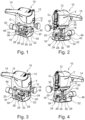
- FIGS 1 to 5 show a handheld power tool 10 which in the present example is a router.
- the handheld power tool 10 comprises a machine body 12 with a gripping portion 14.
- a driving unit is provided inside the machine body 12 and a tool component 16 is operationally coupled to the driving unit.
- the handheld portal 10 is a router
- the tool component 16 may be called a cutter or cutting tool.
- the tool component may be rotated about a tool axis T using the driving unit.
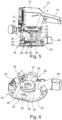
- the handheld power tool 10 additionally comprises a base plate subassembly 18 which is coupled to the machine body 12 via two guiding rods 20 (see also Figures 6 to 8 ).
- the guiding rods 20 are fixedly connected to the base plate subassembly 18.
- the machine body 12 and, thus, the tool component 16 is able to translate along an axis G of the respective guiding rods 20.
- the axis G of the guiding rods 20 and the tool axis T extend in parallel.
- the base plate subassembly 18 comprises a base plate 22 having a contact surface 24 for positioning the handheld power tool 10 on a workpiece (not shown).
- the baseplate 22 comprises an opening 26 which is arranged coaxially to the tool axis T.
- the tool axis T may as well be considered as a middle axis of the opening 26.
- the tool component 16 In order to modify the workpiece or, more generally, to interact with the workpiece, the tool component 16 needs to be rotated about the tool axis T using the driving unit. Moreover, the tool component 16 needs to be positioned such that it extends through the opening 26. This means that at least the tip of the tool component 16 protrudes over the contact surface 24 (cf. Figure 5 ).
- the tool component 16 may be arranged such that it does not extend through the opening 26.
- the tool component 16 may permanently or temporarily extend through the opening 26.
- the handheld power tool 10 of Figures 1 to 5 comprises a lighting assembly 28.
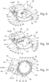
- the lighting assembly 28 is shown separately in Figures 9 to 12 .
- the lighting assembly 28 comprises a lighting module 30 which is arranged on the base plate 22 such that the lighting module 30 is positioned coaxially with the opening 26.
- the lighting assembly 28 comprises a power module 32.
- the power module 32 is supported on the baseplate 22.
- the lighting module 30 and the power module 32 are mechanically and electrically connected as will be explained in more detail further below.
- the lighting module 30 comprises a ring-shaped main body 34.
- the main body 34 is shaped as a fully closed ring.
- the main body 34 has a substantially circular cross-section.
- the main body 34 defines a workspace 36 being configured for enabling an operation of the tool component 16 in the workspace 36. This means that, when operating the handheld power tool with the lighting module 30 installed thereon, the tool component 16 may extend through the interior of the ring-shaped main body 34 (see especially Figure 5 ).
- the main body 34 is shaped as a fully closed ring, the main body 34 circumferentially fully encloses the workspace 36.
- the lighting module 30 comprises a plurality of light sources 38 which are disposed on an interior circumference of the main body 34.
- the light sources 38 are configured for illuminating the workspace 36.
- Each light source 38 comprises one LED.
- the lighting module 30 comprises nine light sources 38 which are arranged equidistantly along the circumference of the main body 34 and the circumference of the workspace 36.
- the main body 34 is made of a fully transparent material, e.g. Polymethylmethacrylate. Consequently, a user of the handheld power tool 10 can see through the main body 34. At the same time, light being generated by the light sources 38 can shine through the main body 34 as well.
- the lighting module 30 additionally fulfills a particle guiding functionality.
- the interior circumferential surface of the main body 34 forms a particle guiding surface 40.
- the particle guiding surface 40 is oriented towards the workspace 36. It hinders workpiece particles, such as workpiece chips, to leave the workspace 36 in an uncontrolled manner.
- the particle guiding functionality is further fulfilled by a cover element 42 of the lighting module 30.
- the cover element 42 is also shaped as a substantially circular ring.
- the cover element 42 is attached to the main body 34 at an upper end thereof, e.g. via a snap-fit.
- the cover element 42 partially closes the upper end of the ring-shaped main body 34 on its upper axial side.
- a central opening 43 of the cover element 42 is configured for receiving the tool component 16.
- the central opening 43 of the cover element 42 has a substantially smaller diameter than the ring-shaped main body 34.
- cover element 42 hinders workpiece particles to leave the workspace 36 in an uncontrolled manner.
- main body 34 is shaped is a fully closed ring, it comprises a suction interface 44 which is formed as a clearance in a circumference of the main body 34.
- the suction interface 44 is positioned adjacent to an end of a suction duct 46. Consequently, workpiece particles may be withdrawn from the workspace 36, i.e. the interior of the ring-shaped main body 34, via the suction interface 44 and the suction duct 46.
- the lighting module 30 further comprises a mechanical power tool connection interface 48.
- the mechanical power tool connection interface 48 is configured for mechanically connecting the lighting module 30 to the handheld power tool 10, more precisely to the base plate 22 of the handheld power tool 10.
- the mechanical power tool connection interface 48 comprises a lateral positioning surface 50 which is formed by an outer circumferential surface of the main body 34.
- the mechanical power tool connection interface 48 comprises three protrusions 52 which extend from an outer circumference of the main body 34. In a mounted position of the lighting module 30, the protrusions 52 are arranged at a lower axial end of the main body 34. This means that the protrusions 52 and the cover element 42 are arranged at opposite axial ends of the main body 34.
- the protrusions 52 are substantially smaller than the remaining parts of the main body 34.
- the main body 34 is approximately ten times higher than the protrusions 52 when considering the axial direction of the main body 34.
- the three protrusions 52 are arranged equidistantly around a circumference of the main body 54. This means that an angular distance between adjacent protrusions 52 equals to 120°. It is understood that this angular distance is measured between respective circumferential centers of the protrusions 52.
- Each of the protrusions 52 has a circumferential extension of 1 to 10°.
- Each of the protrusions 52 comprises an upper abutment surface 54, being oriented upwards in a mounted position of the lighting module 30.
- the upper abutment surfaces 54 are oriented towards the upper end of the lighting module 30, i.e. towards the end at which the cover element 42 is arranged.
- each of the protrusions 52 comprises a lower abutment surface 56.
- the lower abutment surfaces 56 are oriented downwards in a mounted position of the lighting module 30. This means that the lower abutment surfaces 56 are oriented away from the end at which the cover element for 42 is arranged.
- each of the protrusions 52 comprises a first lateral abutment surface 58 and a second lateral abutment surface 60.
- the first lateral abutment surface 58 and the second lateral abutment surface 60 are arranged on opposite circumferential ends of each protrusion 52.
- the main body 34 is arranged inside the opening 26.
- the upper abutment surfaces 54 of the protrusions 52 are abutted against a lower counter-abutment surface 62 of the base plate 22.
- the lower counter-abutment surface of the base plate 22 may be formed by a plurality of abutment surface elements 62a, 62b, 62c. Consequently, the lighting module 30 assumes a defined position on the base plate 22 with respect to an upward direction.
- the lighting module 30 when mounted on the base plate 22, at least one of the first lateral abutment surfaces 58 contacts a first lateral counter-abutment surface 64 of the base plate 22. Additionally, at least 1 of the second lateral abutment surfaces 60 contacts a second lateral counter-abutment surface 66 of the base plate 22. This has the effect that the lighting module 30 is arranged in a defined position with respect to the base plate 22 when considering a rotation around a middle axis of the opening 26.
- the lateral positioning surface 50 is arranged adjacent to an inner circumference of the opening 26 or at least partially contacts the inner circumference of the opening 26. Consequently, the lighting module assumes a defined position with respect to the base plate 22 along a radial direction of the ring-shaped main body 34 which corresponds to a length direction of the base plate 22 and a width direction of the base plate 22.
- the lighting module 30 is further held in its mounted position using a holding ring 68 which is mounted on a lower side of the base plate 22 such that the lower abutment surfaces 56 of the protrusions 52 contact the holding ring 68.
- the holding ring is attached to the base plate using two screws 70.
- the lighting module 30 is fixedly mounted on the base plate 22 in a well-defined position.
- the suction interface 44 is arranged adjacent to the suction duct 46 such that the suction duct 46 is operationally coupled to the workspace 36, i.e. the interior of the ring-shaped main body 34.
- the lighting module 30 comprises a mechanical power module connection interface 72.
- the mechanical power module connection interface 72 is configured for mechanically connecting the lighting module 30 to the power module 32.
- the mechanical power module connection interface 72 comprises a connection recess 74 being configured for receiving a connection protrusion of the power module 32.
- connection recess 74 is arranged at an outer circumference of the main body 34.
- connection recess 74 When being regarded in an axial direction of the ring-shaped main body 34, the connection recess 74 has the form of a dove tail. This means that the connection recess 74 forms two undercuts 76 at its circumferential ends. The undercuts 76 are effective in a radial direction of the ring-shaped main body 34 (see also Figure 11 ).
- the lighting module 34 further comprises an electric power connection interface 78.
- the electric power connection interface 78 is configured for electrically connecting the lighting module 30 to an electric power source, which in the present example is the power module 32.
- the electric power connection interface 78 is configured for electrically connecting the lighting module 30 to a power source which is located inside the machine body 12.
- the electric power connection interface 78 is electrically connected to each of the light sources 38.
- the electric power connection interface 78 comprises two electric contacts 80 which extend from an outer circumference of the main body 34.
- the electric contacts 80 are arranged inside the connection recess 74.
- the electric power connection interface 78 and the mechanical power module connection interface 72 may be considered as being combined.
- the lighting assembly 28 also comprises a power module 32.
- the power module 32 is shown in more detail in Figures 17 and 18 .
- the power module 32 is configured for supplying electric power or, more generally speaking electricity, to the lighting module 30.
- the power module 32 comprises a battery unit 82 which is arranged in a power module housing 84.
- the power module housing 84 comprises a lower surface 86 which is configured for being supported on an upper surface of the base plate 22. Other than that, the power module 32 does not comprise any direct connection to the base plate 22.
- the power module 32 comprises a mechanical connection interface 88.
- the mechanical connection interface 88 is configured for mechanically connecting to the lighting module 30.
- the mechanical connection interface 88 of the power module 32 is configured for engaging the mechanical power module connection interface 72 of the lighting module 30.
- the mechanical connection interface 88 comprises a protrusion 90 which is shaped as a dove tail when being regarded along a height direction of the power module 32. In a mounted condition, they height direction of the power module 32 corresponds to an axial direction of the lighting module 30.
- the protrusion 90 of the mechanical connection interface 88 is shaped and sized such that it can be located inside the connection recess 74 of the mechanical power module connection interface 72 of the lighting module 30.
- connection recess 74 comprises two undercuts 76
- the protrusion 90 may be placed inside the connection recess 74 by moving the lighting module 30 and the power module 32 relative to one another along a height direction of the power module 32.
- the mechanical connection between the lighting module 30 and the power module 32 may be kinematically inverted. This means that a recess may be provided on the power module 32 and a corresponding protrusion may be located on the lighting module.
- the power module 32 comprises an electric connection interface 92.
- the electric connection interface 92 is configured for being electrically connected to the lighting module 30. More precisely, the electric connection interface 92 of the power module 32 comprises two electric contacts 94, wherein each of the electric contacts 94 is configured for being electrically coupled to one of the electric contacts 80 of the electric power connection interface 78 of the lighting module 30. Electric coupling of the electric contacts 94 and the electric contacts 80 may be achieved by abutting the respective contacts against each other.
- the electric contacts 94 are arranged in corresponding recesses provided on the protrusion 90 of the mechanical connection interface 88.
- the electric connection interface 92 is further electrically connected to the battery unit 82. Consequently, electric power from the battery unit 82 may be provided to the light sources 38 of the lighting module 30 if the lighting module 30 and the power module 32 are electrically connected.
- the method is performed using the handheld power tool 10, i.e. the router.
- the handheld power tool 10 comprises a generally known particle guiding element which is arranged in the opening 26 of the base plate 22 of the handheld power tool 10 and which is fixedly connected to the base plate 22 using the holding ring 68.
- An outer diameter of such a particle guiding element thus, substantially corresponds to the inner diameter of the opening 26.
- the particle guiding element may additionally comprise protrusions corresponding to the protrusions 52 of the lighting module 30.
- the outer contour of the particle guiding element may be the same as the outer contour of the lighting module as far as relevant for the connection to the base plate 22.
- the particle guiding element may have a suction interface 44 being substantially identical to the suction interface 44 of the main body 34.
- the particle guiding element is dismounted from the base plate 22.
- the lighting module 30 is attached to the base plate 22.
- the upper abutment surfaces 54 are abutted against the corresponding abutment surface elements 62a, 62b, 62c of the lower counter-abutment surface 62 of the base plate 22.
- At least one of the first lateral abutment surfaces 58 and at least one of the second lateral abutment surfaces 60 is brought into contact with a corresponding first lateral counter-abutment surface 64 and at least one second lateral counter-abutment surface 66.
- the holding ring 68 is attached to the base plate using the screws 70.
- the power module 32 is mechanically and electrically connected to the lighting module 30 as explained above.
- the lower surface 86 of the power module 32 is supported on the upper surface of the base plate 22.
- the workspace 36 and especially the tool component 16 and a portion of a workpiece interacting with the tool component 16 may be illuminated using the light sources 38 of the lighting module 30.
- the lighting module also provides particle guiding functionalities as explained above, workpiece particles may be guided into the suction duct 46 using the lighting module 30.
Landscapes
- Engineering & Computer Science (AREA)
- Mechanical Engineering (AREA)
- Details Of Spanners, Wrenches, And Screw Drivers And Accessories (AREA)
Abstract
A lighting module (30) for a handheld power tool is disclosed. The lighting module (30) comprises a ring-shaped main body (34) forming a workspace (36) configured for disposing a tool component of the handheld power tool. The main body (34) is at least partially transparent or translucent and comprises at least one light source (38), wherein the at least one light source (38) is configured for illuminating the workspace (36). Also a power module (32) for supplying electricity to the lighting module (30) is presented. Moreover, a lighting assembly (28) for a handheld power tool is shown. The lighting assembly (28) comprises the lighting module (30) and the power module (32). Furthermore, a handheld power tool comprising a movable tool is explained. The handheld power tool comprises a base plate and an opening provided therein. A lighting module (30) is arranged on the base plate and the workspace (36) is positioned coaxially to the opening. Moreover, a method for mounting a lighting module (30) on a handheld power tool is described.
Description
- The present invention relates to a lighting module for a handheld power tool having a tool component.
- The present invention is further directed to a power module for supplying electricity to a lighting module for a handheld power tool.
- The present invention additionally relates to a lighting assembly for a handheld power tool.
- Furthermore, the present invention is directed to a handheld power tool and a method for mounting a lighting module on a handheld power tool.
- In handheld power tools, the tool component is configured for interacting with a workpiece in order to perform a desired manufacturing step thereon, e.g. modify the outer shape of the workpiece. In this context, it is important for a user of the power tool to be able to see the tool component and see the portion of the workpiece interacting with the tool component. This allows the user to execute the manufacturing step in a precise manner. In order to enhance the visibility of the tool component and the portion of the workpiece interacting with the tool component, various examples of illumination devices have been disclosed.
- It is an objective of the present invention to provide an improved illumination of the interacting portions of the workpiece and the tool component.
- According to a first aspect of the invention, a lighting module is provided for a handheld power tool having a tool component. The lighting module comprises a ring-shaped main body forming a workspace configured for enabling an operation of the tool component of the handheld power tool in the workspace. The main body is at least partially transparent or translucent. At least one light source is disposed on the main body, wherein the at least one light source is configured for illuminating the workspace. As the main body is ring-shaped and the main body creates a workspace for the tool component and the at least one light source disposed on the main body, the light source is positionable very close to the tool component and the portion of a workpiece interacting with the tool component. This enhances the visibility of both the tool component and the portion of the workpiece. From the perspective of the handheld power tool or the tool component, the ring-shaped main body extends at least partially around the tool component such that the tool component and a portion of the workpiece is capable of being illuminated in a direct manner. Moreover, since the main body is at least partially transparent or translucent, the main body reduces the obstruction of the illumination to a considerable extent. In case the main body is transparent, the user of the handheld power tool whereto the lighting module is connected, would be in a position to even see through the main body. This further enhances the visibility of the tool component and the portion of the workpiece interacting with the tool component. Therewith, an extent of illumination is considerably enhanceable.
- In the context of the present invention, a shape of the light source is variable and is designable based on at least one of the application and structure of the power tool, the workpiece, the workspace, et cetera. In an example, the light source is point-shaped. Such a light source is structurally simple and very compact. Thus, it does not hinder the tool component and/or the portion of the workpiece interacting with the tool component. Moreover, a lighting module comprising such a light source is designable in a very compact manner. In a further example, the light source is line-shaped, and the light source extends substantially along one dimension. According to one aspect, this direction corresponds to a circumferential direction of the main body and/or the workspace. Thus, using such a light source, the tool component and the portion of the workpiece interacting with the tool component is capable of being illuminated from different angles or sides using a single light source. Also, such a light source is compact, at least in a direction perpendicular to its direction of extension. In another example, the light source is a surface light source, whereby the light source extends substantially in two dimensions. The extension of the light source in these two dimensions is substantially equal or different. Using such a light source, the tool component and the workpiece portion interacting with the tool component is capable of being illuminated from multiple angles or sides, whereby enhancing the quality of illumination.
- In an example, the lighting module comprises at least two light sources. The two light sources are disposed at different locations on the main body. The shape of each of the light sources is variable in accordance with one or more of the examples as mentioned above. The two light sources are arrangeable in accordance with a regular pattern. However, this need not be the case always. Thus, the tool component and a portion of the workpiece interacting with the tool component may be illuminated from at least two sides or angles. This avoids the creation of shadows and enhances visibility of the tool component and the portion of the workpiece interacting with the tool component. The lighting module for example comprises two to thirty light sources, preferably two to twenty light sources. In more specific examples, the lighting module comprises 2, 3, 4, 5, 6, 8, 10 or 12 light sources.
- In all of the above examples, each of the one or more light sources may comprise one or more light emitting diodes (LEDs). Using LEDs, an energy-efficient illumination is achievable.
- In another example, the main body is transparent. Consequently, a user of the handheld power tool would be able to see through any portion of the main body. Thus, the main body in its entirety does not obstruct a view of the tool component and/or on the portion of the workpiece interacting with the tool component.
- It is to be noted in the present disclosure, that the term "ring-shaped" comprises both fully closed ring shapes and partially closed ring shapes. In this context, a main body being shaped as a partially closed ring may for example circumferentially enclose the workspace by 90 degrees to 355 degrees. In another example, the main body being shaped as a partially closed ring may circumferentially enclose the workspace by 180 degrees to 355 degrees. It is also possible that the main body being shaped as a partially closed ring may circumferentially enclose the workspace by 270 degrees to 355 degrees. In this context, "circumferentially enclosing" means extending along a circumference of the workspace.
- Since the main body is shaped for receiving the tool component in the workspace, the workspace may also be called a "reception channel" for the tool component.
- In an embodiment, the main body is designed for creating a workspace having a circular, elliptical or polygonal cross section. This means that the interior of the main body defines a circular, elliptical or polygonal shape. As mentioned before, the shape of the main body may resemble a fully or partially closed ring. In this case, the main body has the form of a fully closed, circular, elliptical or polygonal ring. Alternatively, the main body is shaped like a partially closed ring. Consequently, the main body is shaped as a portion of a circle, a portion of an ellipse or a portion of a polygon. An example of a polygon is a quadrangle, such as a rectangle. The shape of the main body is chosen such that it fits a handheld power tool to which the lighting module is connected. This allows to reliably illuminate the tool component and a portion of the workpiece interacting with the tool component.
- According to a further embodiment, the main body circumferentially fully encloses the workspace. In other words, the main body is shaped as a fully closed ring. It is noted that this does not exclude that a height or a thickness of the main body varies along its circumference. Thus, the main body offers the possibility to locate a light source at any desired circumferential position. This allows the light sources to be arranged in a manner that avoids shadows and other undesired optical effects. Moreover, such a main body is mechanically stable.
- The lighting module may comprise at least two light sources which are arranged equidistantly along the perimeter of the main body. In such a configuration, the at least two light sources are also arranged equidistantly along the perimeter of the workspace. This means that all circumferential distances between the at least two light sources are the same. This allows for a uniform illumination of the tool component and the portion of the workpiece interacting with the tool component. At the same time, undesired optical effects such as shadows are reduceable.
- The lighting module may further comprise a mechanical power tool connection interface configured for mechanically connecting the lighting module to the handheld power tool. Thus, the lighting module is reliably secured to the handheld power tool.
- In an example, the lighting module further comprises a mechanical power module connection interface configured for mechanically connecting the lighting module to a power module. The power module is configured for providing electric power to the lighting module. Consequently, the lighting module and the power module is reliably connected. It is understood that a mechanical power module connection interface is only necessary, if the lighting module and the power module are separate from one another.
- The mechanical power module connection interface may be configured as a releasable power module connection interface. Consequently, the lighting module and the power module become selectively separable and selectively connectable.
- It is noted that the mechanical power tool connection interface and power module connection interface of the lighting module may be combined.
- According to a variant, the mechanical power module connection interface comprises a connection protrusion configured for being received in a connection recess of the power module. Alternatively, the mechanical power module connection interface comprises a connection recess being configured for receiving a connection protrusion of the power module. The connection protrusion of the mechanical power module connection interface or the connection recess of the mechanical power module connection interface may have the form of a dove tail. A dovetail shaped connection is both structurally simple and mechanically stable. Moreover, such a connection is easily establishable and releasable by a user of the lighting module or the handheld power tool.
- The lighting module may further comprise an electric power connection interface. The electric power connection interface is configured for electrically connecting the lighting module to an electric power source. The electric power connection interface may be electrically connected to the at least one light source. As a result thereof, electric power is reliably provided to the light sources. In an example, the electric power connection interface is configured for being electrically connected to a power module. In another example, the electric power connection interface is configured for being electrically connected to a power source of the handheld power tool, e.g. a power source, such as a power tool battery pack, that is also used for providing electric power to a drive unit being configured for operating the tool component.
- According to an example, the main body comprises a particle guiding surface. The particle guiding surface is oriented towards the workspace. In this context, a particle is to be understood as a particle of the workpiece, i.e. a workpiece particle such as dust, chips, splinters, shavings, et cetera. This means that the particle is always made of the same material as the workpiece. Thus, in this example, the lighting module not only provides the functionality of illuminating the tool component and the workpiece portion interacting there with, but also a functionality for guiding particles to be removed and/or redirected away from the workspace for enhancing the cleanliness of the workspace. In a special case, the main body forms a part of a particle extraction hood. This means that the main body is used for eliminating particles from a region in which the tool component and the portion of the workpiece interact. Removing particles further enhances the visibility of the tool component and the portion of the workpiece interacting therewith. Additionally, providing both the functionality of illuminating and the functionality of guiding particles by one module, i.e. the lighting module, is structurally simple, compact and cost-efficient.
- In the above example, the lighting module comprising the particle guiding surface may alternatively be considered as a particle guiding element. In this case, the particle guiding element comprises a ring-shaped main body forming a workspace configured for enabling an operation of the tool component of the handheld power tool in the workspace. The main body may be at least partially transparent or translucent. The particle guiding element may additionally comprise at least one light source disposed on the main body, wherein the at least one light source is configured for illuminating the workspace.
- In summary, the lighting module according to the invention may as well be called a particle guiding element.
- According to a second aspect of the invention, a power module is provided for supplying electricity to a lighting module for a handheld power tool. The power module comprises a battery unit, an electric connection interface and a mechanical connection interface. The electric connection interface is configured for electrically connecting to the lighting module. Moreover, the electric connection interface is electrically connected to the battery unit. The mechanical connection interface is configured for mechanically connecting to the lighting module. The lighting module may be a lighting module according to the invention. Such a power module allows to supply electricity or electric power to the lighting module independent from the type or configuration of a handheld power tool to which the lighting module and/or the power module is connected. In other words, using such a power module, a lighting module may be retrofitted to a handheld power tool which is not specifically adapted to the use of a lighting module. Such a possibility to retrofit the lighting module to the handheld power tool makes the lighting module backward-compatible.
- The battery unit of the power module may be configured as a rechargeable battery unit. Additionally and/or alternatively, the battery unit may be releasably connected to the remaining components of the power module.
- According to a third aspect of the invention, a lighting assembly is provided for a handheld power tool. The lighting assembly comprises a lighting module according to the invention and a power module according to the invention. The lighting module and the power module are mechanically and electrically connected. The lighting module and the power module may be connected in a releasable manner. This may apply to both the mechanical and the electrical connection. If the lighting module and the power module are releasably connected, the lighting module and the power module may be easily disconnected, e.g. for changing the power module in case of an empty battery unit. Thus, using the lighting assembly, the tool component and the portion of the workpiece interacting with the tool component may be illuminated in a reliable manner. At the same time, as explained above, the lighting assembly may be used in combination with a great variety of different handheld power tools since the supply of electric energy may be independent from the type or configuration of a handheld power tool. Moreover, such a lighting assembly is structurally simple and compact.
- According to a fourth aspect of the invention, a handheld power tool is provided, the handheld power tool comprising a movable tool component for interacting with a workpiece. Moreover, the handheld power tool comprises a base plate having a contact surface for positioning the handheld power tool on the workpiece. An opening is provided in the base plate and the tool component extends through the opening, especially during an operation of the handheld power tool on the workpiece. A lighting module according to the invention is arranged on the base plate and the workspace is positioned coaxially to the opening. In other words, the lighting module is arranged on the handheld power tool such that the main body of the lighting module fully or partially extends around a circumference of the opening in the base plate. In an alternative, the lighting module is at least partially arranged in the opening. In this position, the lighting module may illuminate the tool component and the portion of the workpiece interacting with the tool component in a reliable manner. It is understood that the tool component may permanently or temporarily extend through the opening. As explained above, the lighting module may be used in combination with a great variety of different handheld power tools since the supply of electric energy may be independent from the type or configuration of a handheld power tool. The installation of the lighting module is chosen such that the lighting module does not disturb the operation of the handheld power tool. The lighting module may be supplied with electric power by the handheld electric power tool or by a power module being separate from the handheld electric power tool.
- As mentioned above, the workspace and/or the main body may have a circular, elliptical or polygonal shape. The same applies to the opening in the base plate, i.e. the opening may have a circular, elliptical or polygonal cross section. Preferably, the shape of the cross section of the opening corresponds to the shape of the workspace and/or the main body. In an example, the cross section of the opening has a circular shape and a main body having a circular shape fully or partially extends around a circumference of the opening. In another example, the cross section of the opening has an elliptical shape and a main body having an elliptical shape fully or partially extends around a circumference of the opening. In a further example, the cross section of the opening has a polygonal shape and a main body having a polygonal shape fully or partially extends around a circumference of the opening. A special form of a polygonal shape is a quadrangular shape. A special form of a quadrangular shape is a rectangular shape.
- The handheld power tool may be a router. The base plate of the router may have an opening with a circular cross section and a main body having a circular shape fully or partially extending around the circumference of the opening.
- Alternatively, the handheld power tool may be a saw such as a jigsaw or a circular saw. The base plate of the saw may have an opening in the form of a slot. In other words, the opening has a polygonal cross section which has the special form of a rectangle. In this case, a main body having a rectangular shape may fully or partially extend around the circumference of the opening.
- In an embodiment, the handheld power tool further comprises a power module according to the invention, wherein the lighting module and the power module are mechanically and electrically connected. The power module may be a power module of the present invention. In such a configuration the lighting module is powered by the power module alone, i.e. not by a power source of the handheld power tool. This makes the power supply simple and independent from a type or configuration of the handheld power tool.
- According to a fifth aspect of the invention, a method is provided for mounting a lighting module on a handheld power tool. The handheld power tool comprises a movable tool component for interacting with a workpiece and a base plate having a contact surface for positioning the handheld power tool on the workpiece. An opening is provided in the base plate and the tool component extends through the opening during an operation of the handheld power tool on the workpiece. The lighting module comprises a main body and at least one light source being disposed on the main body. The method comprises arranging the main body of the lighting module at least partially in the opening such that the at least one light source may illuminate the tool component if the tool component extends through the opening. In this position, the lighting module may illuminate the tool component and the portion of the workpiece interacting with the tool component in a reliable manner. It is understood that the tool component may permanently or temporarily extend through the opening. As explained above, the present method may be used in combination with a great variety of different handheld power tools since the supply of electric energy for the lighting module may be independent from the type or configuration of a handheld power tool. Moreover, in such a configuration, the lighting module does not disturb the operation of the handheld power tool.
- In an example, the method is executed using a lighting module according to the invention.
- In an example, the method further comprises dismounting a particle guiding element from the base plate before arranging the main body of the lighting module at least partially in the opening. In this case, the main body comprises a particle guiding surface. Thus, in other words, a standard particle guiding element is replaced by the lighting module which at the same time fulfills the functionality of guiding particles.
- It is noted that the effects and advantages which are mentioned in connection with one aspect of the invention always apply mutatis mutandis to all other aspects of the invention.
- These and other aspects of the present invention will become apparent from and elucidated with reference to the examples described hereinafter. Examples of the invention will be described in the following with reference to the following drawings.
- Figures 1 and 2
- show a handheld power tool according to the invention from two different perspectives, wherein the handheld power tool comprises a lighting assembly according to the invention, a lighting module according to the invention, and a power module according to the invention, wherein the lighting module may be mounted on the handheld power tool using a method according to the invention,
- Figures 3 and 4
- show the handheld power tool of
Figures 1 and 2 in corresponding perspectives, wherein a cover element of the lighting module is not shown for reasons of better visibility of the remaining components, - Figure 5
- shows the handheld power tool of
Figures 1 to 4 in a side view, - Figures 6 to 8
- show a base plate sub-assembly of the handheld power tool of
Figures 1 to 5 from different perspectives, - Figures 9 to 12
- show the lighting assembly of the handheld power tool of
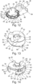
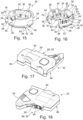
Figures 1 to 5 in a separate representation, wherein inFigures 10 to 12 the cover element of the lighting module is not shown for reasons of better visibility of the remaining components, - Figures 13 to 16
- show the lighting module of the handheld power tool of
Figures 1 to 5 in a separate representation, wherein inFigures 15 and 16 the cover element of the lighting module is not shown for reasons of better visibility of the remaining features of the lighting module, and - Figures 17 and 18
- show the power module of the handheld power tool of
Figures 1 to 5 in a separate representation. -
Figures 1 to 5 show ahandheld power tool 10 which in the present example is a router. - The
handheld power tool 10 comprises amachine body 12 with a grippingportion 14. - Inside the
machine body 12, a driving unit is provided and atool component 16 is operationally coupled to the driving unit. - Since in the present example, the
handheld portal 10 is a router, thetool component 16 may be called a cutter or cutting tool. - The tool component may be rotated about a tool axis T using the driving unit.
- The
handheld power tool 10 additionally comprises abase plate subassembly 18 which is coupled to themachine body 12 via two guiding rods 20 (see alsoFigures 6 to 8 ). In the present example, the guidingrods 20 are fixedly connected to thebase plate subassembly 18. In contrast thereto, themachine body 12 and, thus, thetool component 16 is able to translate along an axis G of therespective guiding rods 20. The axis G of the guidingrods 20 and the tool axis T extend in parallel. - The
base plate subassembly 18 comprises abase plate 22 having acontact surface 24 for positioning thehandheld power tool 10 on a workpiece (not shown). - Moreover, the
baseplate 22 comprises anopening 26 which is arranged coaxially to the tool axis T. Thus, the tool axis T may as well be considered as a middle axis of theopening 26. - In order to modify the workpiece or, more generally, to interact with the workpiece, the
tool component 16 needs to be rotated about the tool axis T using the driving unit. Moreover, thetool component 16 needs to be positioned such that it extends through theopening 26. This means that at least the tip of thetool component 16 protrudes over the contact surface 24 (cf.Figure 5 ). - It is noted that some types of operations to be performed on the workpiece may require to temporarily withdraw the
tool component 16 from the workpiece. In such a situation, thetool component 16 may be arranged such that it does not extend through theopening 26. - Altogether, the
tool component 16 may permanently or temporarily extend through theopening 26. - The
handheld power tool 10 ofFigures 1 to 5 comprises alighting assembly 28. - The
lighting assembly 28 is shown separately inFigures 9 to 12 . - The
lighting assembly 28 comprises alighting module 30 which is arranged on thebase plate 22 such that thelighting module 30 is positioned coaxially with theopening 26. - Moreover, the
lighting assembly 28 comprises apower module 32. - The
power module 32 is supported on thebaseplate 22. - The
lighting module 30 and thepower module 32 are mechanically and electrically connected as will be explained in more detail further below. - In the following, the
lighting module 30 will be explained in more detail with reference toFigures 13 to 16 showing thelighting module 30 in an isolated representation. - The
lighting module 30 comprises a ring-shapedmain body 34. - In the present example, the
main body 34 is shaped as a fully closed ring. - Moreover, in the present example, the
main body 34 has a substantially circular cross-section. - In its interior, the
main body 34 defines aworkspace 36 being configured for enabling an operation of thetool component 16 in theworkspace 36. This means that, when operating the handheld power tool with thelighting module 30 installed thereon, thetool component 16 may extend through the interior of the ring-shaped main body 34 (see especiallyFigure 5 ). - Due to the fact that the
main body 34 is shaped as a fully closed ring, themain body 34 circumferentially fully encloses theworkspace 36. - The
lighting module 30 comprises a plurality oflight sources 38 which are disposed on an interior circumference of themain body 34. Thelight sources 38 are configured for illuminating theworkspace 36. - Each
light source 38 comprises one LED. - In the present example, the
lighting module 30 comprises ninelight sources 38 which are arranged equidistantly along the circumference of themain body 34 and the circumference of theworkspace 36. - The
main body 34 is made of a fully transparent material, e.g. Polymethylmethacrylate. Consequently, a user of thehandheld power tool 10 can see through themain body 34. At the same time, light being generated by thelight sources 38 can shine through themain body 34 as well. - In the present example, the
lighting module 30 additionally fulfills a particle guiding functionality. - In this context, the interior circumferential surface of the
main body 34 forms aparticle guiding surface 40. Theparticle guiding surface 40 is oriented towards theworkspace 36. It hinders workpiece particles, such as workpiece chips, to leave theworkspace 36 in an uncontrolled manner. - The particle guiding functionality is further fulfilled by a
cover element 42 of thelighting module 30. - The
cover element 42 is also shaped as a substantially circular ring. - The
cover element 42 is attached to themain body 34 at an upper end thereof, e.g. via a snap-fit. - Thus, the
cover element 42 partially closes the upper end of the ring-shapedmain body 34 on its upper axial side. - A
central opening 43 of thecover element 42 is configured for receiving thetool component 16. - Thereby, the
central opening 43 of thecover element 42 has a substantially smaller diameter than the ring-shapedmain body 34. - Thus, also the
cover element 42 hinders workpiece particles to leave theworkspace 36 in an uncontrolled manner. - Even though the
main body 34 is shaped is a fully closed ring, it comprises asuction interface 44 which is formed as a clearance in a circumference of themain body 34. - In a situation in which the
lighting module 30 is mounted on thebase plate 22 of the handheld power tool 10 (see especiallyFigure 6 ), thesuction interface 44 is positioned adjacent to an end of asuction duct 46. Consequently, workpiece particles may be withdrawn from theworkspace 36, i.e. the interior of the ring-shapedmain body 34, via thesuction interface 44 and thesuction duct 46. - The
lighting module 30 further comprises a mechanical powertool connection interface 48. The mechanical powertool connection interface 48 is configured for mechanically connecting thelighting module 30 to thehandheld power tool 10, more precisely to thebase plate 22 of thehandheld power tool 10. - In this context, the mechanical power
tool connection interface 48 comprises alateral positioning surface 50 which is formed by an outer circumferential surface of themain body 34. - Beyond that, the mechanical power
tool connection interface 48 comprises threeprotrusions 52 which extend from an outer circumference of themain body 34. In a mounted position of thelighting module 30, theprotrusions 52 are arranged at a lower axial end of themain body 34. This means that theprotrusions 52 and thecover element 42 are arranged at opposite axial ends of themain body 34. - Along an axial direction of the
main body 34 which may also be called a height direction of themain body 34, theprotrusions 52 are substantially smaller than the remaining parts of themain body 34. - In the present example, the
main body 34 is approximately ten times higher than theprotrusions 52 when considering the axial direction of themain body 34. - The three
protrusions 52 are arranged equidistantly around a circumference of themain body 54. This means that an angular distance betweenadjacent protrusions 52 equals to 120°. It is understood that this angular distance is measured between respective circumferential centers of theprotrusions 52. Each of theprotrusions 52 has a circumferential extension of 1 to 10°. - Each of the
protrusions 52 comprises anupper abutment surface 54, being oriented upwards in a mounted position of thelighting module 30. In other words, the upper abutment surfaces 54 are oriented towards the upper end of thelighting module 30, i.e. towards the end at which thecover element 42 is arranged. - Moreover, each of the
protrusions 52 comprises alower abutment surface 56. The lower abutment surfaces 56 are oriented downwards in a mounted position of thelighting module 30. This means that the lower abutment surfaces 56 are oriented away from the end at which the cover element for 42 is arranged. - Additionally, each of the
protrusions 52 comprises a firstlateral abutment surface 58 and a secondlateral abutment surface 60. The firstlateral abutment surface 58 and the secondlateral abutment surface 60 are arranged on opposite circumferential ends of eachprotrusion 52. - In a situation in which the
lighting module 30 is mounted on thebase plate 22 of thehandheld power tool 10, themain body 34 is arranged inside theopening 26. - In this position, the upper abutment surfaces 54 of the
protrusions 52 are abutted against a lower counter-abutment surface 62 of thebase plate 22. The lower counter-abutment surface of thebase plate 22 may be formed by a plurality of abutment surface elements 62a, 62b, 62c. Consequently, thelighting module 30 assumes a defined position on thebase plate 22 with respect to an upward direction. - Moreover, when mounted on the
base plate 22, at least one of the first lateral abutment surfaces 58 contacts a first lateral counter-abutment surface 64 of thebase plate 22. Additionally, at least 1 of the second lateral abutment surfaces 60 contacts a second lateral counter-abutment surface 66 of thebase plate 22. This has the effect that thelighting module 30 is arranged in a defined position with respect to thebase plate 22 when considering a rotation around a middle axis of theopening 26. - Further, in the mounted position, the
lateral positioning surface 50 is arranged adjacent to an inner circumference of theopening 26 or at least partially contacts the inner circumference of theopening 26. Consequently, the lighting module assumes a defined position with respect to thebase plate 22 along a radial direction of the ring-shapedmain body 34 which corresponds to a length direction of thebase plate 22 and a width direction of thebase plate 22. - The
lighting module 30 is further held in its mounted position using a holdingring 68 which is mounted on a lower side of thebase plate 22 such that the lower abutment surfaces 56 of theprotrusions 52 contact the holdingring 68. - The holding ring is attached to the base plate using two
screws 70. - Altogether, the
lighting module 30 is fixedly mounted on thebase plate 22 in a well-defined position. In this position, thesuction interface 44 is arranged adjacent to thesuction duct 46 such that thesuction duct 46 is operationally coupled to theworkspace 36, i.e. the interior of the ring-shapedmain body 34. - Beyond that, the
lighting module 30 comprises a mechanical power module connection interface 72. - The mechanical power module connection interface 72 is configured for mechanically connecting the
lighting module 30 to thepower module 32. - In the present example, the mechanical power module connection interface 72 comprises a
connection recess 74 being configured for receiving a connection protrusion of thepower module 32. - The
connection recess 74 is arranged at an outer circumference of themain body 34. - When being regarded in an axial direction of the ring-shaped
main body 34, theconnection recess 74 has the form of a dove tail. This means that theconnection recess 74 forms twoundercuts 76 at its circumferential ends. The undercuts 76 are effective in a radial direction of the ring-shaped main body 34 (see alsoFigure 11 ). - The
lighting module 34 further comprises an electric power connection interface 78. - The electric power connection interface 78 is configured for electrically connecting the
lighting module 30 to an electric power source, which in the present example is thepower module 32. - In a non-represented alternative, the electric power connection interface 78 is configured for electrically connecting the
lighting module 30 to a power source which is located inside themachine body 12. - The electric power connection interface 78 is electrically connected to each of the
light sources 38. - The electric power connection interface 78 comprises two
electric contacts 80 which extend from an outer circumference of themain body 34. - The
electric contacts 80 are arranged inside theconnection recess 74. - Thus, the electric power connection interface 78 and the mechanical power module connection interface 72 may be considered as being combined.
- As mentioned before, the
lighting assembly 28 also comprises apower module 32. - The
power module 32 is shown in more detail inFigures 17 and 18 . - The
power module 32 is configured for supplying electric power or, more generally speaking electricity, to thelighting module 30. - To this end, the
power module 32 comprises abattery unit 82 which is arranged in apower module housing 84. - The
power module housing 84 comprises alower surface 86 which is configured for being supported on an upper surface of thebase plate 22. Other than that, thepower module 32 does not comprise any direct connection to thebase plate 22. - However, the
power module 32 comprises a mechanical connection interface 88. The mechanical connection interface 88 is configured for mechanically connecting to thelighting module 30. In more detail, the mechanical connection interface 88 of thepower module 32 is configured for engaging the mechanical power module connection interface 72 of thelighting module 30. - The mechanical connection interface 88 comprises a
protrusion 90 which is shaped as a dove tail when being regarded along a height direction of thepower module 32. In a mounted condition, they height direction of thepower module 32 corresponds to an axial direction of thelighting module 30. - The
protrusion 90 of the mechanical connection interface 88 is shaped and sized such that it can be located inside theconnection recess 74 of the mechanical power module connection interface 72 of thelighting module 30. - Due to the fact that the
connection recess 74 comprises twoundercuts 76, theprotrusion 90 may be placed inside theconnection recess 74 by moving thelighting module 30 and thepower module 32 relative to one another along a height direction of thepower module 32. - It is noted that in an alternative, the mechanical connection between the
lighting module 30 and thepower module 32 may be kinematically inverted. This means that a recess may be provided on thepower module 32 and a corresponding protrusion may be located on the lighting module. - Beyond that, the
power module 32 comprises an electric connection interface 92. - The electric connection interface 92 is configured for being electrically connected to the
lighting module 30. More precisely, the electric connection interface 92 of thepower module 32 comprises twoelectric contacts 94, wherein each of theelectric contacts 94 is configured for being electrically coupled to one of theelectric contacts 80 of the electric power connection interface 78 of thelighting module 30. Electric coupling of theelectric contacts 94 and theelectric contacts 80 may be achieved by abutting the respective contacts against each other. - In the present example, the
electric contacts 94 are arranged in corresponding recesses provided on theprotrusion 90 of the mechanical connection interface 88. - Thus, also in the
power module 32, the mechanical connection interface 88 and the electric connection interface 92 are combined. - This has the effect that, when mechanically connecting the power module and the
lighting module 30 as explained above, thepower module 32 and thelighting module 30 are also electrically coupled. - The electric connection interface 92 is further electrically connected to the
battery unit 82. Consequently, electric power from thebattery unit 82 may be provided to thelight sources 38 of thelighting module 30 if thelighting module 30 and thepower module 32 are electrically connected. - In the following, a method for mounting the
lighting module 30 on thehandheld power tool 10 will be explained. - The method is performed using the
handheld power tool 10, i.e. the router. - It is assumed that the
handheld power tool 10 comprises a generally known particle guiding element which is arranged in theopening 26 of thebase plate 22 of thehandheld power tool 10 and which is fixedly connected to thebase plate 22 using the holdingring 68. - An outer diameter of such a particle guiding element, thus, substantially corresponds to the inner diameter of the
opening 26. The particle guiding element may additionally comprise protrusions corresponding to theprotrusions 52 of thelighting module 30. In other words, the outer contour of the particle guiding element may be the same as the outer contour of the lighting module as far as relevant for the connection to thebase plate 22. - Moreover, the particle guiding element may have a
suction interface 44 being substantially identical to thesuction interface 44 of themain body 34. - In a first step of the method, the particle guiding element is dismounted from the
base plate 22. - This means that the
screws 70 are opened and the holdingring 68 is withdrawn from thebase plate 22. Then, the particle guiding element is withdrawn from theopening 26. - Subsequently, the
lighting module 30 is attached to thebase plate 22. - This means that the
main body 34 is arranged in theopening 26 of thebase plate 22. - Thereby, the upper abutment surfaces 54 are abutted against the corresponding abutment surface elements 62a, 62b, 62c of the lower counter-abutment surface 62 of the
base plate 22. - In order to arrange the
lighting module 30 in a desired rotational position, at least one of the first lateral abutment surfaces 58 and at least one of the second lateral abutment surfaces 60 is brought into contact with a corresponding first lateral counter-abutment surface 64 and at least one second lateral counter-abutment surface 66. - Subsequently, the holding
ring 68 is attached to the base plate using thescrews 70. - In a next step, the
power module 32 is mechanically and electrically connected to thelighting module 30 as explained above. In a condition in which thepower module 32 and thelighting module 30 are connected, thelower surface 86 of thepower module 32 is supported on the upper surface of thebase plate 22. - Consequently, the
workspace 36 and especially thetool component 16 and a portion of a workpiece interacting with thetool component 16 may be illuminated using thelight sources 38 of thelighting module 30. - Moreover, due to the fact that the lighting module also provides particle guiding functionalities as explained above, workpiece particles may be guided into the
suction duct 46 using thelighting module 30. -
- 10
- handheld power tool
- 12
- machine body
- 14
- gripping portion
- 16
- tool component
- 18
- base plate sub-assembly
- 20
- guiding rod
- 22
- base plate
- 24
- contact surface of the base plate
- 26
- opening of the base plate
- 28
- lighting assembly
- 30
- lighting module
- 32
- power module
- 34
- main body of the lighting module
- 36
- workspace
- 38
- light source
- 40
- particle guiding surface
- 42
- cover element
- 43
- central opening of the cover element
- 44
- suction interface
- 46
- suction duct
- 48
- mechanical power tool connection interface
- 50
- lateral positioning surface
- 52
- protrusion
- 54
- upper abutment surface
- 56
- lower abutment surface
- 58
- first lateral abutment surface
- 60
- second lateral abutment surface
- 62
- lower counter-abutment surface
- 62a
- abutment surface element
- 62b
- abutment surface element
- 62c
- abutment surface element
- 64
- first lateral counter-abutment surface
- 66
- second lateral counter-abutment surface
- 68
- holding ring
- 70
- screw
- 72
- mechanical power module connection interface
- 74
- connection recess
- 76
- undercut
- 78
- electric power connection interface
- 80
- electric contact
- 82
- battery unit
- 84
- power module housing
- 86
- lower surface
- 88
- mechanical connection interface
- 90
- protrusion
- 92
- electric connection interface
- 94
- electric contact
- G
- axis of the guiding rods
- T
- tool axis
Claims (15)
- A lighting module (30) for a handheld power tool (10) having a tool component (16), the lighting module (30) comprising- a ring-shaped main body (34) forming a workspace (36) configured for enabling an operation of the tool component (16) of the handheld power tool (10) in the workspace (36), wherein the main body (34) is at least partially transparent or translucent, and- at least one light source (38) disposed on the main body (34), wherein the at least one light source (38) is configured for illuminating the workspace (36).
- The lighting module (30) of claim 1, wherein the workspace (36) has a circular, elliptical or polygonal cross section.
- The lighting module (30) of claim 1 or 2, wherein the main body (34) circumferentially fully encloses the workspace (36).
- The lighting module (30) of any one of the preceding claims, comprising at least two light sources (38) arranged equidistantly along a perimeter of the main body (34).
- The lighting module (30) of any one of the preceding claims, further comprising a mechanical power tool connection interface (48) configured for mechanically connecting the lighting module (30) to the handheld power tool (10).
- The lighting module (30) of any one of the preceding claims, further comprising a mechanical power module connection interface (72) configured for mechanically connecting the lighting module (30) to a power module (32).
- The lighting module (30) of claim 6, wherein the mechanical power module connection interface (72) comprises a connection protrusion configured for being received in a connection recess of the power module (32) or a connection recess (74) being configured for receiving a connection protrusion of the power module (32),
wherein the connection protrusion of the mechanical power module connection interface (72) or the connection recess (74) of the mechanical power module connection interface (72) has the form of a dove tail. - The lighting module (30) of any one of the preceding claims, further comprising an electric power connection interface (78), wherein the electric power connection interface (78) is configured for electrically connecting the lighting module (30) to an electric power source, wherein the electric power connection interface (78) is electrically connected to the at least one light source (38).
- The lighting module (30) of any one of the preceding claims, wherein the main body (34) comprises a particle guiding surface (40), wherein the particle guiding surface (40) is oriented towards the workspace (36).
- A power module (32) for supplying electricity to a lighting module (30) for a handheld power tool (10), the power module (32)comprising a battery unit (82), an electric connection interface (92) and a mechanical connection interface (88),wherein the electric connection interface (92) is configured for electrically connecting to the lighting module (30), and wherein the electric connection interface (92) is electrically connected to the battery unit (82), andwherein the mechanical connection interface (88) is configured for mechanically connecting to the lighting module (30).
- A lighting assembly (28) for a handheld power tool (10), comprising a lighting module (30) of any one of claims 1 to 9 and a power module (32) of claim 10, wherein the lighting module (30) and the power module (32) are mechanically and electrically connected.
- A handheld power tool (10), comprising a movable tool component (16) for interacting with a workpiece and a base plate (22) having a contact surface (24) for positioning the handheld power tool (10) on the workpiece,wherein an opening (26) is provided in the base plate (22) and the tool component (16) extends through the opening (26) during an operation of the handheld power tool (10) on the workpiece,wherein a lighting module (30) according to any one of claims 1 to 9 is arranged on the base plate (22) and the workspace (36) is positioned coaxially to the opening (26).
- The handheld power tool (10) of claim 12, further comprising a power module (32) according to claim 10, wherein the lighting module (30) and the power module (32) are mechanically and electrically connected.
- A method for mounting a lighting module (30) on a handheld power tool (10),
wherein the handheld power tool (10) comprises a movable tool component (16) for interacting with a workpiece and a base plate (22) having a contact surface (24) for positioning the handheld power tool (10) on the workpiece, wherein an opening (26) is provided in the base plate (22) and the tool component (16) extends through the opening (26) during an operation of the handheld power tool (10) on the workpiece, wherein the lighting module (30) comprises a main body (34) and at least one light source (38) being disposed on the main body (34), the method comprising:arranging the main body (34) of the lighting module (30) at least partially in the opening (26) such that the at least one light source (38) may illuminate the tool component (16) if the tool component (16) extends through the opening (26). - The method of claim 14, further comprising dismounting a particle guiding element from the base plate (22) before arranging the main body (34) of the lighting module (30) at least partially in the opening (26).
Priority Applications (1)
| Application Number | Priority Date | Filing Date | Title |
|---|---|---|---|
| EP23170596.3A EP4454824A1 (en) | 2023-04-28 | 2023-04-28 | Lighting module for a handheld power tool, power module, lighting assembly, handheld power tool, and method for mounting a lighting module on a handheld power tool |
Applications Claiming Priority (1)
| Application Number | Priority Date | Filing Date | Title |
|---|---|---|---|
| EP23170596.3A EP4454824A1 (en) | 2023-04-28 | 2023-04-28 | Lighting module for a handheld power tool, power module, lighting assembly, handheld power tool, and method for mounting a lighting module on a handheld power tool |
Publications (1)
| Publication Number | Publication Date |
|---|---|
| EP4454824A1 true EP4454824A1 (en) | 2024-10-30 |
Family
ID=86282514
Family Applications (1)
| Application Number | Title | Priority Date | Filing Date |
|---|---|---|---|
| EP23170596.3A Pending EP4454824A1 (en) | 2023-04-28 | 2023-04-28 | Lighting module for a handheld power tool, power module, lighting assembly, handheld power tool, and method for mounting a lighting module on a handheld power tool |
Country Status (1)
| Country | Link |
|---|---|
| EP (1) | EP4454824A1 (en) |
Citations (5)
| Publication number | Priority date | Publication date | Assignee | Title |
|---|---|---|---|---|
| DE102009011423A1 (en) * | 2009-03-03 | 2010-09-09 | Schneider Druckluft Gmbh | Pneumatic hand tool e.g. drilling press, has electrical lighting device provided with light and arranged at housing for lighting up work area of tool, and compressed air outlet provided for blowing compressed air |
| US8919979B2 (en) * | 2012-10-31 | 2014-12-30 | All Clear Fire Systems, Llc | Electronic apparatus for hose attachment to enhance visibility, communication, atmospheric monitoring, early detection and warning for fire fighter scene safety and method therefor |
| EP3369531A1 (en) * | 2017-03-01 | 2018-09-05 | Robert Bosch GmbH | Base plate with integrated workpiece illumination |
| US10900658B1 (en) * | 2019-12-06 | 2021-01-26 | Taizhou Beswell Machinery Co., Ltd. | Light fixture for repair tools |
| DE112020006654T5 (en) * | 2020-01-31 | 2022-11-24 | Koki Holdings Co., Ltd. | work machine |
-
2023
- 2023-04-28 EP EP23170596.3A patent/EP4454824A1/en active Pending
Patent Citations (5)
| Publication number | Priority date | Publication date | Assignee | Title |
|---|---|---|---|---|
| DE102009011423A1 (en) * | 2009-03-03 | 2010-09-09 | Schneider Druckluft Gmbh | Pneumatic hand tool e.g. drilling press, has electrical lighting device provided with light and arranged at housing for lighting up work area of tool, and compressed air outlet provided for blowing compressed air |
| US8919979B2 (en) * | 2012-10-31 | 2014-12-30 | All Clear Fire Systems, Llc | Electronic apparatus for hose attachment to enhance visibility, communication, atmospheric monitoring, early detection and warning for fire fighter scene safety and method therefor |
| EP3369531A1 (en) * | 2017-03-01 | 2018-09-05 | Robert Bosch GmbH | Base plate with integrated workpiece illumination |
| US10900658B1 (en) * | 2019-12-06 | 2021-01-26 | Taizhou Beswell Machinery Co., Ltd. | Light fixture for repair tools |
| DE112020006654T5 (en) * | 2020-01-31 | 2022-11-24 | Koki Holdings Co., Ltd. | work machine |
Similar Documents
| Publication | Publication Date | Title |
|---|---|---|
| JP3874990B2 (en) | Lighting equipment for cutting machine | |
| EP3386683B1 (en) | Rotary power tool lighting system | |
| US20050044728A1 (en) | Power hand tool right angle attachment having a light source with a self-generating power supply | |
| CN1493436A (en) | electrical tools | |
| GB2387808A (en) | Power saw with laser alignment system | |
| JP2013059820A (en) | Electric tool | |
| EP4454824A1 (en) | Lighting module for a handheld power tool, power module, lighting assembly, handheld power tool, and method for mounting a lighting module on a handheld power tool | |
| US20160059321A1 (en) | Magnetically mountable portable drill assembly | |
| CN113682805A (en) | Grab mechanism and transfer device | |
| US12410911B2 (en) | Work machine | |
| CN1774166A (en) | Suction nozzle receptacle structure of suction nozzle change unit and surface mounting machine | |
| JP5280422B2 (en) | Cutting machine | |
| US20050098011A1 (en) | Circular saw with a sawing path indicating device | |
| CN207900362U (en) | Saw | |
| CN116214232A (en) | A replaceable milling tool | |
| CN101176999A (en) | Cutting device and laser module for use with the cutting device | |
| JP7665412B2 (en) | Assistive devices | |
| CN119604378A (en) | Handheld Circular Saw | |
| JP4860842B2 (en) | Cutting machine | |
| JP2022187143A (en) | Cutting blade exchange device | |
| CN221390897U (en) | Multifunctional tool | |
| JP2003048118A (en) | Cutter | |
| JP3727627B2 (en) | Cutting machine | |
| JP4936225B2 (en) | Portable cutting machine | |
| CN222199112U (en) | Saw |
Legal Events
| Date | Code | Title | Description |
|---|---|---|---|
| PUAI | Public reference made under article 153(3) epc to a published international application that has entered the european phase |
Free format text: ORIGINAL CODE: 0009012 |
|
| STAA | Information on the status of an ep patent application or granted ep patent |
Free format text: STATUS: THE APPLICATION HAS BEEN PUBLISHED |
|
| AK | Designated contracting states |
Kind code of ref document: A1 Designated state(s): AL AT BE BG CH CY CZ DE DK EE ES FI FR GB GR HR HU IE IS IT LI LT LU LV MC ME MK MT NL NO PL PT RO RS SE SI SK SM TR |
|
| STAA | Information on the status of an ep patent application or granted ep patent |
Free format text: STATUS: REQUEST FOR EXAMINATION WAS MADE |
|
| 17P | Request for examination filed |
Effective date: 20250411 |