EP4454777A1 - Press-molding method and press-molded article manufacturing method - Google Patents
Press-molding method and press-molded article manufacturing method Download PDFInfo
- Publication number
- EP4454777A1 EP4454777A1 EP22926050.0A EP22926050A EP4454777A1 EP 4454777 A1 EP4454777 A1 EP 4454777A1 EP 22926050 A EP22926050 A EP 22926050A EP 4454777 A1 EP4454777 A1 EP 4454777A1
- Authority
- EP
- European Patent Office
- Prior art keywords
- forming
- press
- forming step
- shoulder
- die
- Prior art date
- Legal status (The legal status is an assumption and is not a legal conclusion. Google has not performed a legal analysis and makes no representation as to the accuracy of the status listed.)
- Pending
Links
- 238000000034 method Methods 0.000 title claims abstract description 49
- 238000004519 manufacturing process Methods 0.000 title claims abstract description 14
- 238000000465 moulding Methods 0.000 title 1
- 238000005452 bending Methods 0.000 claims abstract description 51
- 230000002093 peripheral effect Effects 0.000 claims abstract description 29
- 239000002184 metal Substances 0.000 claims abstract description 18
- 229910000831 Steel Inorganic materials 0.000 claims description 9
- 239000010959 steel Substances 0.000 claims description 9
- 230000037303 wrinkles Effects 0.000 description 29
- 238000009826 distribution Methods 0.000 description 10
- 230000000694 effects Effects 0.000 description 7
- 238000007796 conventional method Methods 0.000 description 4
- 239000000463 material Substances 0.000 description 4
- 238000009966 trimming Methods 0.000 description 4
- 238000004458 analytical method Methods 0.000 description 3
- 230000006872 improvement Effects 0.000 description 3
- CURLTUGMZLYLDI-UHFFFAOYSA-N Carbon dioxide Chemical compound O=C=O CURLTUGMZLYLDI-UHFFFAOYSA-N 0.000 description 2
- 230000007423 decrease Effects 0.000 description 2
- 238000010586 diagram Methods 0.000 description 2
- 238000003825 pressing Methods 0.000 description 2
- 230000008569 process Effects 0.000 description 2
- 230000001629 suppression Effects 0.000 description 2
- 239000013585 weight reducing agent Substances 0.000 description 2
- 238000013459 approach Methods 0.000 description 1
- 230000033228 biological regulation Effects 0.000 description 1
- 230000015572 biosynthetic process Effects 0.000 description 1
- 229910002092 carbon dioxide Inorganic materials 0.000 description 1
- 239000001569 carbon dioxide Substances 0.000 description 1
- 230000008859 change Effects 0.000 description 1
- 239000012141 concentrate Substances 0.000 description 1
- 238000005516 engineering process Methods 0.000 description 1
- 239000000446 fuel Substances 0.000 description 1
- 230000009467 reduction Effects 0.000 description 1
- 230000004044 response Effects 0.000 description 1
- 238000012795 verification Methods 0.000 description 1
Images



Classifications
-
- B—PERFORMING OPERATIONS; TRANSPORTING
- B21—MECHANICAL METAL-WORKING WITHOUT ESSENTIALLY REMOVING MATERIAL; PUNCHING METAL
- B21D—WORKING OR PROCESSING OF SHEET METAL OR METAL TUBES, RODS OR PROFILES WITHOUT ESSENTIALLY REMOVING MATERIAL; PUNCHING METAL
- B21D22/00—Shaping without cutting, by stamping, spinning, or deep-drawing
- B21D22/20—Deep-drawing
- B21D22/26—Deep-drawing for making peculiarly, e.g. irregularly, shaped articles
-
- B—PERFORMING OPERATIONS; TRANSPORTING
- B21—MECHANICAL METAL-WORKING WITHOUT ESSENTIALLY REMOVING MATERIAL; PUNCHING METAL
- B21D—WORKING OR PROCESSING OF SHEET METAL OR METAL TUBES, RODS OR PROFILES WITHOUT ESSENTIALLY REMOVING MATERIAL; PUNCHING METAL
- B21D19/00—Flanging or other edge treatment, e.g. of tubes
- B21D19/08—Flanging or other edge treatment, e.g. of tubes by single or successive action of pressing tools, e.g. vice jaws
-
- B—PERFORMING OPERATIONS; TRANSPORTING
- B21—MECHANICAL METAL-WORKING WITHOUT ESSENTIALLY REMOVING MATERIAL; PUNCHING METAL
- B21D—WORKING OR PROCESSING OF SHEET METAL OR METAL TUBES, RODS OR PROFILES WITHOUT ESSENTIALLY REMOVING MATERIAL; PUNCHING METAL
- B21D22/00—Shaping without cutting, by stamping, spinning, or deep-drawing
- B21D22/20—Deep-drawing
- B21D22/22—Deep-drawing with devices for holding the edge of the blanks
-
- B—PERFORMING OPERATIONS; TRANSPORTING
- B21—MECHANICAL METAL-WORKING WITHOUT ESSENTIALLY REMOVING MATERIAL; PUNCHING METAL
- B21D—WORKING OR PROCESSING OF SHEET METAL OR METAL TUBES, RODS OR PROFILES WITHOUT ESSENTIALLY REMOVING MATERIAL; PUNCHING METAL
- B21D24/00—Special deep-drawing arrangements in, or in connection with, presses
-
- B—PERFORMING OPERATIONS; TRANSPORTING
- B21—MECHANICAL METAL-WORKING WITHOUT ESSENTIALLY REMOVING MATERIAL; PUNCHING METAL
- B21D—WORKING OR PROCESSING OF SHEET METAL OR METAL TUBES, RODS OR PROFILES WITHOUT ESSENTIALLY REMOVING MATERIAL; PUNCHING METAL
- B21D24/00—Special deep-drawing arrangements in, or in connection with, presses
- B21D24/005—Multi-stage presses
-
- B—PERFORMING OPERATIONS; TRANSPORTING
- B21—MECHANICAL METAL-WORKING WITHOUT ESSENTIALLY REMOVING MATERIAL; PUNCHING METAL
- B21D—WORKING OR PROCESSING OF SHEET METAL OR METAL TUBES, RODS OR PROFILES WITHOUT ESSENTIALLY REMOVING MATERIAL; PUNCHING METAL
- B21D5/00—Bending sheet metal along straight lines, e.g. to form simple curves
- B21D5/01—Bending sheet metal along straight lines, e.g. to form simple curves between rams and anvils or abutments
-
- B—PERFORMING OPERATIONS; TRANSPORTING
- B21—MECHANICAL METAL-WORKING WITHOUT ESSENTIALLY REMOVING MATERIAL; PUNCHING METAL
- B21D—WORKING OR PROCESSING OF SHEET METAL OR METAL TUBES, RODS OR PROFILES WITHOUT ESSENTIALLY REMOVING MATERIAL; PUNCHING METAL
- B21D53/00—Making other particular articles
- B21D53/88—Making other particular articles other parts for vehicles, e.g. cowlings, mudguards
Definitions
- the present invention relates to a press forming method and a press formed part manufacturing method, being a method of forming a press formed part including a top portion, a side wall portion, and a flange portion.
- the present invention relates particularly to a press forming method and a press formed part manufacturing method capable of suppressing occurrence of wrinkles associated with shrink flange forming performed at formation of the press formed part.
- automotive parts include a part having a top portion, a side wall portion, and a flange portion, such as an A pillar upper, an A pillar lower, and a bumper.
- a part having a top portion, a side wall portion, and a flange portion such as an A pillar upper, an A pillar lower, and a bumper.
- the side wall portion and the flange portion of the portion might be subjected to shrink flange forming during press forming, leading to occurrence of wrinkles at the end of the flange portion.
- buckling is likely to occur due to an increase in strength, increasing probability of occurrence of wrinkles.
- Patent Literature 1 describes a press forming method of suppressing wrinkles, specifically, when forming a press formed part that includes a top portion and a slanted wall continuous with at least one side of the top portion and having no flange at its distal end and in which the entire or a part of the slanted wall is curved in a convex shape toward the slanted wall in a longitudinal direction of the press formed part in a planar view, the suppression of wrinkles is performed by a concave die and a convex punch.
- this method uses procedures in which the portion on a position near the end of the portion corresponding to a slanted wall in the blank sheet is clamped between the die and the punch in the middle of forming, and the slanted wall is formed in a state where the portion near the end is clamped, thereby preventing buckling of the blank sheet in the thickness direction so as to suppress wrinkles occurring in the slanted wall.
- Patent Literature 2 describes a method of manufacturing a press formed part in which wrinkles are suppressed when a metal sheet is press formed into a product shape, that is, a shape having a hat-shaped cross section in which a top portion and a flange portion are continuous in a width direction via a side wall and having a curved portion in which the top portion and the flange portion are curved in a convex shape toward the top portion in a longitudinal direction.
- the method includes a stepped drawing step, being a step of setting a blank holder region that holds the metal sheet with a blank holder on an outer peripheral portion of a flange portion position and performing forming with stepped drawing.
- an additional region of pressing with a blank holder is also set at a partial portion of the flange portion position, thereby suppressing wrinkles occurring in the flange portion.
- the press forming method described in Patent Literature 1 performs forming of the slanted wall in a state where a portion of the blank sheet closer to the end with respect to a portion corresponding to the slanted wall is clamped between the die and the punch, making it necessary, in the next step, to trim the portion clamped between the die and the punch. Furthermore, the press forming method described in Patent Literature 1 has a problem that the method is not applicable to the forming of a press formed part having a flange portion continuous with a side wall portion (slanted wall).
- the press formed part manufacturing method described in Patent Literature 2 is applicable to the forming of a press formed part having a flange portion, but since this method uses a blank holder, and thus has a problem that the technique is not applicable to press forming by bending (crash forming).
- the present invention has been made to solve the above problems, and aims to provide a press forming method and a press formed part manufacturing method capable of sufficiently suppress wrinkles on a flange portion caused by shrink flange forming and that is also applicable to bending, without requiring a trimming step after press forming.
- a press forming method is the press forming method of forming a press formed part, the press formed part including: a top portion having a convex peripheral edge having a whole of or part of an outer peripheral edge curved outward in a convex shape; a side wall portion continuous to the top portion via a punch shoulder R portion; and a flange portion continuous to the side wall portion via a die shoulder R portion.
- the press forming method includes: a first forming step of forming a metal sheet into a preformed part; and a second forming step of forming the preformed part formed in the first forming step into the press formed part having a target shape, wherein the first forming step performs forming such that a bending radius of the die shoulder R portion formed corresponding to at least the convex peripheral edge of the top portion of the preformed part is larger than a bending radius of the die shoulder R portion of the press formed part having the target shape.
- first forming step may apply drawing or bending
- second forming step may apply bending
- the metal sheet may be a steel sheet having a tensile strength of 590 MPa or more.
- a press formed part manufacturing method is the method of manufacturing a press formed part, the press formed part including: a top portion having a convex peripheral edge having a whole of or part of an outer peripheral edge curved outward in a convex shape; a side wall portion continuous to the top portion via a punch shoulder R portion; and a flange portion continuous to the side wall portion via a die shoulder R portion.
- the method includes: a first forming step of forming a metal sheet into a preformed part; and a second forming step of forming the preformed part formed in the first forming step into the press formed part having a target shape, wherein the first forming step performs forming such that a bending radius of the die shoulder R portion formed corresponding to at least the convex peripheral edge of the top portion of the preformed part is larger than a bending radius of the die shoulder R portion of the press formed part having the target shape.
- the present invention includes: a first forming step of forming a metal sheet into a preformed part; and a second forming step of forming the preformed part into a press formed part having a target shape.
- the preformed part is formed so that the bending radius of the die shoulder R portion is larger than the bending radius of the die shoulder R portion of the press formed part having a target shape, making it possible to suppress wrinkles on the flange portion caused by the shrink flange forming.
- this method it is possible to obtain a press formed part having a satisfactory shape without wrinkles, leading to an improvement in yield ratio in press forming.
- the conventional trimming step is not necessarily needed.
- the method is also applicable to bending.
- FIG. 2 illustrates a portion of a press formed part.
- a press formed part 1 illustrated in FIG. 2 includes a top portion 3, a side wall portion 5, and a flange portion 7, and has a portion (hereinafter, referred to as a "convex peripheral edge 3a") in which an outer peripheral edge of the top portion 3 is partially curved outward in a convex shape.
- the boundary between the convex peripheral edge 3a and the other portions is defined as a position up to a curved end of the convex peripheral edge 3a in a planar view of the top portion 3, for example.
- the boundary portion between the top portion 3 and the side wall portion 5 has a rounded (R) shape corresponding to the shape of the shoulder portion of the punch used for the press forming. Accordingly, when simply described as a "punch shoulder R portion” in the present specification, the portion refers to the portion on the press formed part 1 side. Similarly, since the boundary portion between the side wall portion 5 and the flange portion 7 has an R shape corresponding to the shape of the shoulder portion of the die, when simply described as “die shoulder R portion", the portion refers to the portion on the press formed part 1 side.
- FIG. 9 is a result of FEM analysis on a case where the press formed part 1 is press formed by a conventional method, in which distribution of the thickness increase rate is indicated by a shade of color.
- the thickness increase rate is represented by a rate (ratio) of the thickness of the press formed part after press forming to the thickness of the blank before the press forming obtained from their difference (thickness increment), and the larger the value, the higher the rate of increase in the sheet thickness.
- the forming of the side wall portion 5 and the flange portion 7 corresponding to the convex peripheral edge 3a of the top portion 3 corresponds to shrink flange forming, which concentrates the material and wrinkles are likely to occur.
- the sheet thickness increased the most at the end of the flange portion 7 indicated by the arrow in the drawing, where the maximum sheet thickness increase rate was +12.5%. In this manner, a local increase of the sheet thickness causes occurrence of wrinkles in the corresponding portion, which has been a problem.
- the press forming method of the present embodiment is provided to enable application of bending while reducing the occurrence of wrinkles in the flange portion 7 as compared with the conventional technology.
- the press forming method according to the present embodiment is a method of forming the press formed part 1 as illustrated in an example in FIG. 2 , the press formed part 1 including: the top portion 3 having the convex peripheral edge 3a in which a portion of the outer peripheral edge is curved outward in a convex shape; the side wall portion 5 continuing to the top portion 3 via the punch shoulder R portion; and the flange portion 7 continuing to the side wall portion 5 via the die shoulder R portion.
- the press forming method according to the present embodiment includes: a first forming step of forming a blank 13 being a metal sheet into a preformed part 17; and a second forming step of forming the preformed part 17 into the press formed part 1 having a target shape.
- FIG. 1 illustrates a state before forming of a portion corresponding to the A-A' cross section of FIG. 2(b) in each step.
- the press formed part 1 is manufactured by executing the press forming method, and thus, the invention of the press forming method can also be the invention of a press formed part manufacturing method. Therefore, the embodiment of the press forming method described below is common to the embodiment of the press formed part manufacturing method. Hereinafter, each step will be described in detail.
- the first forming step is a step of press forming the blank 13, which is a metal sheet, into a preformed part 17 described below.
- the shape of the die shoulder R portion at a boundary portion between the side wall portion 5 and the flange portion 7 formed by the shrink flange forming is different from the target shape. This point will be specifically described below.
- a die 15 is moved relative to a punch 9 in a state where a part of the blank 13 is clamped between the upper surface of the punch 9 and a pad 11, thereby forming the preformed part 17.
- the forming surface of the die 15 has a shape corresponding to the target shape except for a shoulder portion 15a, but a curvature radius R 1 of the shoulder portion 15a is larger than a curvature radius R 0 of a shoulder portion 21a of the die 21 (R 0 ⁇ R 1 ) for which the target shape is to be formed in the second forming step.
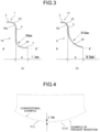
- FIG. 3(a) illustrates a state of a bottom dead center of a portion corresponding to the A-A' cross section when the target shape of FIG. 2 is formed by a conventional method.
- FIG. 3(b) illustrates a state of a bottom dead center of a portion corresponding to the A-A' cross section when the preformed part 17 is formed in the first forming step of the present embodiment.
- the set of mold of the conventional example in FIG. 3(a) has the same shape as the set of mold used in the second forming step illustrated in FIG. 1(b) , and thus, is denoted by the same reference numeral.
- FIGS. 3(a) and 3(b) omit illustration of dies.
- the boundary portion between the top portion 3 and the side wall portion 5 in the target shape and the preformed part 17 is a portion having an R shape along a shoulder portion 19a of a punch 19 or a shoulder portion 9a of the punch 9. Accordingly, this portion of the target shape and the preformed part 17 is referred to as a punch shoulder R portion 23.
- the boundary portion between the side wall portion 5 and the flange portion 7 is a portion having an R shape along the shoulder portion 21a of the die 21 or the shoulder portion 15a of the die 15 (refer to FIG. 1 ), and thus, this portion in the target shape and the preformed part 17 is referred to as a die shoulder R portion 25.
- the die shoulder R portion 25 of the preformed part 17 is formed so that the bending radius of the die shoulder R portion 25 is to be larger than the bending radius of the die shoulder R portion 25 ( FIG. 3(a) ) of the target shape.
- the bending radius of the die shoulder R portion 25 of the target shape is set to R4 mm, and in contrast to this, the bending radius of the die shoulder R portion 25 of the preformed part 17 is set to R10 mm.
- a distance a from the curved end of the punch shoulder R portion 23 of the preformed part 17 closer to the side wall portion 5 to the blank end at the bottom dead center is longer than the distance a in the target shape.
- the distance a of the target shape in FIG. 3(a) is 7.3 mm
- the distance a of the preformed part 17 in FIG. 3(b) is 9.5 mm, which is 2.2 mm longer.
- FIG. 4 illustrates a comparison between the target shape in FIG. 3(a) and the shape of the preformed part 17 in FIG. 3(b) in planar view.
- FIG. 4 illustrates an outer peripheral line when the target shape and the preformed part 17 are overlapped together with their top portions 3 being aligned with each other.
- FIG. 4 also illustrates that the end of the flange portion 7 of the preformed part 17 (example of present invention) is positioned about 2.2 mm outside the target shape (conventional example).
- the deformation amount of the side wall portion 5 and the flange portion 7 becomes smaller compared to the target shape, and thus, wrinkles due to the shrink flange forming are less likely to occur at the corresponding portion of the preformed part 17.
- the portions on which the bending radius of the die shoulder R portion 25 of the preformed part 17 is set to be larger than the bending radius of the die shoulder R portion 25 of the target shape may be portions over the entire length of the die shoulder R portion 25 (the entire length of the ridgeline between the side wall portion 5 and the flange portion 7), or may be portions to be subjected to shrink flange forming. That is, it is sufficient to set the bending radius of the die shoulder R portion 25 of the portion formed continuously with the side wall portion 5 corresponding to at least the convex peripheral edge 3a in the preformed part 17 to be larger than the bending radius of the die shoulder R portion 25 of the target shape.
- the bending radius of the die shoulder R portion 25 of the preformed part 17 is to be preferably set to 1.2 to 5 times the bending radius of the die shoulder R portion 25 of the target shape. Furthermore, it is more preferable to set with the magnification of 1.2 times to 3 times. This is to optimize the gap between the punch 19 and the die 21 at the start of the shrink flange forming in the second forming step described below.
- the second forming step is a step of forming the preformed part 17 formed in the first forming step into the press formed part 1 having a target shape.
- the punch 19 and the die 21, which are a set of mold used in the second forming step have the same shapes as the punch 9 and the die 15, which are a set of mold used in the first forming step, except for the forming portion of the die shoulder R portion 25. Therefore, this step also serves as "restrike" for reducing springback by re-pressing the formed part with the same set of mold.
- the punch shoulder R portion 23 of the preformed part 17 is set to fit with the shoulder portion 19a of the punch 19, and the die 21 is lowered in a state where the top portion 3 of the preformed part 17 is clamped between the punch 19 and the pad 11, thereby forming the preformed part 17 into the press formed part 1 having the target shape.
- the die 21 has a shape corresponding to the target shape as described above.
- the curvature radius R 0 of the shoulder portion 21a of the die 21 is smaller than the curvature radius R 1 of the shoulder portion 15a of the die 15 used in the first forming step. (R 0 ⁇ R 1 ).
- FIG. 5 illustrates a change in appearance of the die shoulder R portion 25 in the forming process of the second forming step and a state of the forming process of a portion corresponding to the A-A' cross section of FIG. 2 .
- a numerical value such as "5 mm up” is a distance to the bottom dead center of the die 21 in consideration of the sheet thickness of the preformed part 17. Accordingly, the gap between the punch 19 and the die 21 in the press forming direction at "5 mm up” corresponds to the size obtained by adding +5 mm to the sheet thickness of the preformed part 17. With the decrease in the numerical value, the die 21 approaches the punch 19 to move forward with the forming, so as to reach the bottom dead center at "0 mm up".
- the die shoulder R portion 25 starts to be formed from the point 1 mm before the bottom dead center.
- the portion is subjected to shrink flange forming.
- the gap between the punch 19 and the die 21 is as small as a size obtained by adding +1 mm to the sheet thickness at the start of the shrink flange forming, and thereafter, the gap further decreases up to the bottom dead center, making it possible to suppress local concentration of the material. Therefore, wrinkles are less likely to occur at the end of the flange portion 7 also in the second forming step.
- FIG. 6 illustrates the distribution of the thickness increase rate of the preformed part 17 formed in the first forming step of the present embodiment.
- the thickness increase rate and the shade of color are similar to those in FIG. 9 .
- the maximum sheet thickness increase rate of the conventional example in FIG. 9 is +12.5%
- the maximum sheet thickness increase rate of the preformed part 17 of the present embodiment is +6.5%, which made it possible to halve the increase in the thickness of the portion that is subjected to shrink flange forming.
- FIG. 7 illustrates the distribution of the thickness increase rate when the preformed part 17 in FIG. 6 is formed into a target shape in the second forming step.
- the maximum sheet thickness increase rate after the second forming step of the present embodiment was +7.3%, which was an increase as small as 0.8% from the maximum sheet thickness increase rate of the preformed part 17.
- the press formed part 1 manufactured by the press forming method of the present embodiment sufficiently reduces the increase in the sheet thickness of the portion where shrink flange forming is performed as compared with the press formed part 1 manufactured by the conventional method, having an effect of suppressing the occurrence of wrinkles at the portion.
- FIG. 8(a) illustrates the distribution of the thickness increase rate of the preformed part 17 at the bottom dead center in the first forming step.
- FIG. 8(b) is a distribution of the thickness increase rate of the press formed part 1 at the bottom dead center in the second forming step. The distribution of the thickness increase rate is illustrated in a range narrower than the range illustrated in FIGS. 6 and 7 .
- the increase in the sheet thickness is dispersed in a wider range than in the first forming step. This indicates that the strain in the shrink flange forming in the second forming step is dispersed over a wide range, making it possible to suppress an occurrence of a local increase in sheet thickness and occurrence of wrinkles.
- the press forming method of the present embodiment can suppress wrinkles of the flange portion 7 without using a blank holder, and thus is applicable to press forming by bending forming (crash forming). That is, the present method is particularly effective when drawing or bending is applied in the first forming step of forming the preformed part 17 and bending is applied in the second forming step of forming the target shape.
- the press forming method of the present embodiment is particularly effective when using a high-strength steel sheet which is likely to have wrinkles by shrink flange forming.
- the metal sheet (blank) may be a steel sheet having a tensile strength of 590 MPa or more, and even in this case, it is possible to have a sufficient effect of reducing wrinkles.
- Item No. 1 is a conventional example in which a target shape is directly formed from a metal sheet in one step.
- Items No. 2 to No. 5 are examples of the present invention performed in two steps including: a first step of forming a metal sheet into the preformed part 17 (first forming step in the embodiment) and; a second step of forming the preformed part 17 into a target shape (second forming step in the embodiment).
- the bending radius of the die shoulder R portion 25 of the preformed part 17 was varied to four patterns of 6 mm, 8 mm, 10 mm, and 12 mm.
- the maximum sheet thickness increase rate in the first step was 5.2%, which was further reduced as compared with other examples of the present invention, but the maximum sheet thickness increase rate in the second step was 8.9%, which was reduced as compared with the conventional example but increased as compared with the other examples of the present invention. Consequently, in the present example, it was found that the thickness increase rate can be most reduced in the example of Item No. 4.
- the sheet thickness increase in the first forming step is reduced, but the sheet thickness tends to increase in the second forming step. This is because the larger the bending radius of the die shoulder R portion of the preformed part, the earlier the forming start timing of the die shoulder R portion in the second forming step, which increases the gap between the punch and the die at the time of starting the forming of the die shoulder R portion, leading to reduction of the wrinkle suppressing effect.
- the bending radius of the die shoulder R portion of the preformed part is too large, the forming of the die shoulder R portion is started before the gap between the punch and the die becomes sufficiently small in the second forming step, leading to a case having difficulty in suppressing local concentration of the material.
- a press forming method and a press formed part manufacturing method capable of sufficiently suppress wrinkles of a flange portion caused by shrink flange forming and that is also applicable to bending, without requiring a trimming step after press forming.
Landscapes
- Engineering & Computer Science (AREA)
- Mechanical Engineering (AREA)
- Shaping Metal By Deep-Drawing, Or The Like (AREA)
Abstract
Description
- The present invention relates to a press forming method and a press formed part manufacturing method, being a method of forming a press formed part including a top portion, a side wall portion, and a flange portion. The present invention relates particularly to a press forming method and a press formed part manufacturing method capable of suppressing occurrence of wrinkles associated with shrink flange forming performed at formation of the press formed part.
- Along with the progress of improvement of collision safety of an automotive body due to tightening of automotive collision safety standards, a weight reduction of automotive body is also required to achieve improved fuel efficiency and electrification of vehicles (EV) in response to carbon dioxide emission regulations. In order to achieve both collision safety improvement and weight reduction of the automotive body, application of high-strength steel sheets (also referred to as high-tensile steel sheets) of 590 MPa class or higher to automotive body structural parts is in progress. The press forming of a high-tensile steel sheet into automotive body structural parts has a problem of how wrinkles caused by shrinkage flange forming can be suppressed.
- For example, automotive parts include a part having a top portion, a side wall portion, and a flange portion, such as an A pillar upper, an A pillar lower, and a bumper. In such a part, when a whole or a part of an outer peripheral edge of the top portion is curved outward in a convex shape, the side wall portion and the flange portion of the portion might be subjected to shrink flange forming during press forming, leading to occurrence of wrinkles at the end of the flange portion. In the case of a high-tensile steel sheet in particular, buckling is likely to occur due to an increase in strength, increasing probability of occurrence of wrinkles.
- To handle this,
Patent Literature 1 describes a press forming method of suppressing wrinkles, specifically, when forming a press formed part that includes a top portion and a slanted wall continuous with at least one side of the top portion and having no flange at its distal end and in which the entire or a part of the slanted wall is curved in a convex shape toward the slanted wall in a longitudinal direction of the press formed part in a planar view, the suppression of wrinkles is performed by a concave die and a convex punch. More specifically, this method uses procedures in which the portion on a position near the end of the portion corresponding to a slanted wall in the blank sheet is clamped between the die and the punch in the middle of forming, and the slanted wall is formed in a state where the portion near the end is clamped, thereby preventing buckling of the blank sheet in the thickness direction so as to suppress wrinkles occurring in the slanted wall. - In addition,
Patent Literature 2 describes a method of manufacturing a press formed part in which wrinkles are suppressed when a metal sheet is press formed into a product shape, that is, a shape having a hat-shaped cross section in which a top portion and a flange portion are continuous in a width direction via a side wall and having a curved portion in which the top portion and the flange portion are curved in a convex shape toward the top portion in a longitudinal direction. Specifically, the method includes a stepped drawing step, being a step of setting a blank holder region that holds the metal sheet with a blank holder on an outer peripheral portion of a flange portion position and performing forming with stepped drawing. When forming is performed by the stepped drawing, an additional region of pressing with a blank holder is also set at a partial portion of the flange portion position, thereby suppressing wrinkles occurring in the flange portion. -
- Patent Literature 1:
JP 2016-221558 A - Patent Literature 2:
JP 2018-034176 A - However, the press forming method described in
Patent Literature 1 performs forming of the slanted wall in a state where a portion of the blank sheet closer to the end with respect to a portion corresponding to the slanted wall is clamped between the die and the punch, making it necessary, in the next step, to trim the portion clamped between the die and the punch. Furthermore, the press forming method described inPatent Literature 1 has a problem that the method is not applicable to the forming of a press formed part having a flange portion continuous with a side wall portion (slanted wall). - In this respect, the press formed part manufacturing method described in
Patent Literature 2 is applicable to the forming of a press formed part having a flange portion, but since this method uses a blank holder, and thus has a problem that the technique is not applicable to press forming by bending (crash forming). - The present invention has been made to solve the above problems, and aims to provide a press forming method and a press formed part manufacturing method capable of sufficiently suppress wrinkles on a flange portion caused by shrink flange forming and that is also applicable to bending, without requiring a trimming step after press forming.
- To solve the problem and achieve the object, a press forming method according to the present invention is the press forming method of forming a press formed part, the press formed part including: a top portion having a convex peripheral edge having a whole of or part of an outer peripheral edge curved outward in a convex shape; a side wall portion continuous to the top portion via a punch shoulder R portion; and a flange portion continuous to the side wall portion via a die shoulder R portion. The press forming method includes: a first forming step of forming a metal sheet into a preformed part; and a second forming step of forming the preformed part formed in the first forming step into the press formed part having a target shape, wherein the first forming step performs forming such that a bending radius of the die shoulder R portion formed corresponding to at least the convex peripheral edge of the top portion of the preformed part is larger than a bending radius of the die shoulder R portion of the press formed part having the target shape.
- Moreover, the first forming step may apply drawing or bending, and the second forming step may apply bending.
- Moreover, the metal sheet may be a steel sheet having a tensile strength of 590 MPa or more.
- Moreover, a press formed part manufacturing method according to the present invention is the method of manufacturing a press formed part, the press formed part including: a top portion having a convex peripheral edge having a whole of or part of an outer peripheral edge curved outward in a convex shape; a side wall portion continuous to the top portion via a punch shoulder R portion; and a flange portion continuous to the side wall portion via a die shoulder R portion. The method includes: a first forming step of forming a metal sheet into a preformed part; and a second forming step of forming the preformed part formed in the first forming step into the press formed part having a target shape, wherein the first forming step performs forming such that a bending radius of the die shoulder R portion formed corresponding to at least the convex peripheral edge of the top portion of the preformed part is larger than a bending radius of the die shoulder R portion of the press formed part having the target shape.
- The present invention includes: a first forming step of forming a metal sheet into a preformed part; and a second forming step of forming the preformed part into a press formed part having a target shape. In the first forming step, the preformed part is formed so that the bending radius of the die shoulder R portion is larger than the bending radius of the die shoulder R portion of the press formed part having a target shape, making it possible to suppress wrinkles on the flange portion caused by the shrink flange forming. With this method, it is possible to obtain a press formed part having a satisfactory shape without wrinkles, leading to an improvement in yield ratio in press forming. In addition, since there is no need to clamp the end of the blank with the punch and the die, the conventional trimming step is not necessarily needed. Furthermore, since no blank holder is required, the method is also applicable to bending.
-
-
FIG. 1 is a view illustrating a press forming method according to an embodiment of the present invention. -
FIG. 2 is a view illustrating a part (target shape) as an application target in the embodiment, in whichFIG. 2(a) is a perspective view, andFIG. 2(b) is a plan view. -
FIG. 3 includes a view (FIG. 3(a) ) illustrating a state of a bottom dead center when a target shape is formed by a method according to a conventional example, and a view (FIG. 3(b) ) illustrating a state of a bottom dead center when the preformed part is formed in the first forming step of the embodiment. -
FIG. 4 is a plan view illustrating overlapping outer peripheral lines of a bottom dead center when a target shape is formed inFIG. 3(a) and a bottom dead center when a preformed part is formed inFIG. 3(b) in planar view. -
FIG. 5 is a view illustrating a second forming step according to the embodiment. -
FIG. 6 is a diagram illustrating a thickness increase rate distribution of the preformed part that has been press formed in the first forming step. -
FIG. 7 is a diagram illustrating a thickness increase rate distribution of a press formed part that has been press formed into a target shape in the second forming step. -
FIG. 8 is a view comparing the thickness increase rate distribution of the preformed part inFIG. 6 with the thickness increase rate distribution of the press formed part that has been press formed into the target shape inFIG. 7 . -
FIG. 9 is a view illustrating a problem in a case where the part illustrated inFIG. 2 is press formed by a method of a conventional example. - A press formed part as an application target of the press forming method according to the present embodiment will be described with reference to
FIG. 2. FIG. 2 illustrates a portion of a press formed part. A press formedpart 1 illustrated inFIG. 2 includes atop portion 3, aside wall portion 5, and aflange portion 7, and has a portion (hereinafter, referred to as a "convexperipheral edge 3a") in which an outer peripheral edge of thetop portion 3 is partially curved outward in a convex shape. The boundary between the convexperipheral edge 3a and the other portions is defined as a position up to a curved end of the convexperipheral edge 3a in a planar view of thetop portion 3, for example. In addition, the boundary portion between thetop portion 3 and theside wall portion 5 has a rounded (R) shape corresponding to the shape of the shoulder portion of the punch used for the press forming. Accordingly, when simply described as a "punch shoulder R portion" in the present specification, the portion refers to the portion on the press formedpart 1 side. Similarly, since the boundary portion between theside wall portion 5 and theflange portion 7 has an R shape corresponding to the shape of the shoulder portion of the die, when simply described as "die shoulder R portion", the portion refers to the portion on the press formedpart 1 side. These portions will be described in detail below. - First, before describing the press forming method according to the present embodiment, problems in the case of press forming the press formed
part 1 as illustrated inFIG. 2 by a conventional method will be described with reference toFIG. 9. FIG. 9 is a result of FEM analysis on a case where the press formedpart 1 is press formed by a conventional method, in which distribution of the thickness increase rate is indicated by a shade of color. The thickness increase rate is represented by a rate (ratio) of the thickness of the press formed part after press forming to the thickness of the blank before the press forming obtained from their difference (thickness increment), and the larger the value, the higher the rate of increase in the sheet thickness. - When press forming is performed to obtain the press formed
part 1 as illustrated inFIG. 2 , the forming of theside wall portion 5 and theflange portion 7 corresponding to the convexperipheral edge 3a of thetop portion 3 corresponds to shrink flange forming, which concentrates the material and wrinkles are likely to occur. In the example ofFIG. 9 , the sheet thickness increased the most at the end of theflange portion 7 indicated by the arrow in the drawing, where the maximum sheet thickness increase rate was +12.5%. In this manner, a local increase of the sheet thickness causes occurrence of wrinkles in the corresponding portion, which has been a problem. Therefore, conventionally, a means of preventing buckling in the thickness direction by utilizing a blank holder for theflange portion 7 has been used, but this means has not been sufficiently effective. In addition, use of a blank holder leads to drawing, which has caused a problem that bending cannot be applied. - In view of this, the press forming method of the present embodiment is provided to enable application of bending while reducing the occurrence of wrinkles in the
flange portion 7 as compared with the conventional technology. - Specifically, the press forming method according to the present embodiment is a method of forming the press formed
part 1 as illustrated in an example inFIG. 2 , the press formedpart 1 including: thetop portion 3 having the convexperipheral edge 3a in which a portion of the outer peripheral edge is curved outward in a convex shape; theside wall portion 5 continuing to thetop portion 3 via the punch shoulder R portion; and theflange portion 7 continuing to theside wall portion 5 via the die shoulder R portion. As illustrated inFIG. 1 , the press forming method according to the present embodiment includes: a first forming step of forming a blank 13 being a metal sheet into apreformed part 17; and a second forming step of forming thepreformed part 17 into the press formedpart 1 having a target shape.FIG. 1 illustrates a state before forming of a portion corresponding to the A-A' cross section ofFIG. 2(b) in each step. The press formedpart 1 is manufactured by executing the press forming method, and thus, the invention of the press forming method can also be the invention of a press formed part manufacturing method. Therefore, the embodiment of the press forming method described below is common to the embodiment of the press formed part manufacturing method. Hereinafter, each step will be described in detail. - The first forming step is a step of press forming the blank 13, which is a metal sheet, into a
preformed part 17 described below. In thepreformed part 17 formed in the first forming step, the shape of the die shoulder R portion at a boundary portion between theside wall portion 5 and theflange portion 7 formed by the shrink flange forming is different from the target shape. This point will be specifically described below. - In the first forming step, as illustrated in
FIG. 1(a) , adie 15 is moved relative to apunch 9 in a state where a part of the blank 13 is clamped between the upper surface of thepunch 9 and apad 11, thereby forming thepreformed part 17. The forming surface of the die 15 has a shape corresponding to the target shape except for ashoulder portion 15a, but a curvature radius R1 of theshoulder portion 15a is larger than a curvature radius R0 of ashoulder portion 21a of the die 21 (R0 < R1) for which the target shape is to be formed in the second forming step. - The shape of the preformed
part 17 according to the present invention when the first forming step is performed using a set of mold (punch and die) as described above will be described with an example illustrated inFIG. 3. FIG. 3(a) illustrates a state of a bottom dead center of a portion corresponding to the A-A' cross section when the target shape ofFIG. 2 is formed by a conventional method.FIG. 3(b) illustrates a state of a bottom dead center of a portion corresponding to the A-A' cross section when thepreformed part 17 is formed in the first forming step of the present embodiment. The set of mold of the conventional example inFIG. 3(a) has the same shape as the set of mold used in the second forming step illustrated inFIG. 1(b) , and thus, is denoted by the same reference numeral.FIGS. 3(a) and 3(b) omit illustration of dies. - As illustrated in
FIGS. 3(a) and 3(b) , the boundary portion between thetop portion 3 and theside wall portion 5 in the target shape and thepreformed part 17 is a portion having an R shape along ashoulder portion 19a of apunch 19 or ashoulder portion 9a of thepunch 9. Accordingly, this portion of the target shape and thepreformed part 17 is referred to as a punchshoulder R portion 23. Similarly, the boundary portion between theside wall portion 5 and theflange portion 7 is a portion having an R shape along theshoulder portion 21a of the die 21 or theshoulder portion 15a of the die 15 (refer toFIG. 1 ), and thus, this portion in the target shape and thepreformed part 17 is referred to as a dieshoulder R portion 25. In the first forming step, as illustrated inFIG. 3(b) , using the set of mold illustrated inFIG. 1(a) , the dieshoulder R portion 25 of the preformedpart 17 is formed so that the bending radius of the dieshoulder R portion 25 is to be larger than the bending radius of the die shoulder R portion 25 (FIG. 3(a) ) of the target shape. In the example ofFIG. 3 , the bending radius of the dieshoulder R portion 25 of the target shape is set to R4 mm, and in contrast to this, the bending radius of the dieshoulder R portion 25 of the preformedpart 17 is set to R10 mm. - By using the settings as described above, a distance a from the curved end of the punch
shoulder R portion 23 of the preformedpart 17 closer to theside wall portion 5 to the blank end at the bottom dead center is longer than the distance a in the target shape. Specifically, the distance a of the target shape inFIG. 3(a) is 7.3 mm, whereas the distance a of the preformedpart 17 inFIG. 3(b) is 9.5 mm, which is 2.2 mm longer. -
FIG. 4 illustrates a comparison between the target shape inFIG. 3(a) and the shape of the preformedpart 17 inFIG. 3(b) in planar view.FIG. 4 illustrates an outer peripheral line when the target shape and thepreformed part 17 are overlapped together with theirtop portions 3 being aligned with each other. Similarly toFIG. 3, FIG. 4 also illustrates that the end of theflange portion 7 of the preformed part 17 (example of present invention) is positioned about 2.2 mm outside the target shape (conventional example). - As described above, by increasing the bending radius of the die
shoulder R portion 25 of the preformedpart 17, the deformation amount of theside wall portion 5 and theflange portion 7 becomes smaller compared to the target shape, and thus, wrinkles due to the shrink flange forming are less likely to occur at the corresponding portion of the preformedpart 17. - The portions on which the bending radius of the die
shoulder R portion 25 of the preformedpart 17 is set to be larger than the bending radius of the dieshoulder R portion 25 of the target shape may be portions over the entire length of the die shoulder R portion 25 (the entire length of the ridgeline between theside wall portion 5 and the flange portion 7), or may be portions to be subjected to shrink flange forming. That is, it is sufficient to set the bending radius of the dieshoulder R portion 25 of the portion formed continuously with theside wall portion 5 corresponding to at least the convexperipheral edge 3a in the preformedpart 17 to be larger than the bending radius of the dieshoulder R portion 25 of the target shape. The bending radius of the dieshoulder R portion 25 of the preformedpart 17 is to be preferably set to 1.2 to 5 times the bending radius of the dieshoulder R portion 25 of the target shape. Furthermore, it is more preferable to set with the magnification of 1.2 times to 3 times. This is to optimize the gap between thepunch 19 and the die 21 at the start of the shrink flange forming in the second forming step described below. - The second forming step is a step of forming the
preformed part 17 formed in the first forming step into the press formedpart 1 having a target shape. As described above, thepunch 19 and thedie 21, which are a set of mold used in the second forming step, have the same shapes as thepunch 9 and thedie 15, which are a set of mold used in the first forming step, except for the forming portion of the dieshoulder R portion 25. Therefore, this step also serves as "restrike" for reducing springback by re-pressing the formed part with the same set of mold. - In the second forming step, as illustrated in
FIG. 1(b) , the punchshoulder R portion 23 of the preformedpart 17 is set to fit with theshoulder portion 19a of thepunch 19, and thedie 21 is lowered in a state where thetop portion 3 of the preformedpart 17 is clamped between thepunch 19 and thepad 11, thereby forming thepreformed part 17 into the press formedpart 1 having the target shape. Thedie 21 has a shape corresponding to the target shape as described above. In addition, the curvature radius R0 of theshoulder portion 21a of the die 21 is smaller than the curvature radius R1 of theshoulder portion 15a of the die 15 used in the first forming step. (R0<R1). - When the
side wall portion 5 and theflange portion 7 corresponding to the convexperipheral edge 3a of the preformedpart 17 are formed into the target shape using thepunch 19 and thedie 21, the portions are subjected to shrink flange forming. However, occurrence of wrinkles can also be suppressed in the shrink flange forming in the second forming step. The reason will be described with reference toFIG. 5 . -
FIG. 5 illustrates a change in appearance of the dieshoulder R portion 25 in the forming process of the second forming step and a state of the forming process of a portion corresponding to the A-A' cross section ofFIG. 2 . A numerical value such as "5 mm up" is a distance to the bottom dead center of the die 21 in consideration of the sheet thickness of the preformedpart 17. Accordingly, the gap between thepunch 19 and the die 21 in the press forming direction at "5 mm up" corresponds to the size obtained by adding +5 mm to the sheet thickness of the preformedpart 17. With the decrease in the numerical value, the die 21 approaches thepunch 19 to move forward with the forming, so as to reach the bottom dead center at "0 mm up". - In the second forming step of the present embodiment, when the
preformed part 17 is set on the upper surface of thepunch 19 and thedie 21 is lowered, as illustrated inFIG. 5 , the dieshoulder R portion 25 starts to be formed from thepoint 1 mm before the bottom dead center. When the dieshoulder R portion 25 is formed into the target shape, the portion is subjected to shrink flange forming. However, the gap between thepunch 19 and thedie 21 is as small as a size obtained by adding +1 mm to the sheet thickness at the start of the shrink flange forming, and thereafter, the gap further decreases up to the bottom dead center, making it possible to suppress local concentration of the material. Therefore, wrinkles are less likely to occur at the end of theflange portion 7 also in the second forming step. - Effects of the present embodiment described above will be specifically described with reference to
FIGS. 6 and7 .FIG. 6 illustrates the distribution of the thickness increase rate of the preformedpart 17 formed in the first forming step of the present embodiment. The thickness increase rate and the shade of color are similar to those inFIG. 9 . As illustrated inFIG. 6 , while the maximum sheet thickness increase rate of the conventional example inFIG. 9 is +12.5%, the maximum sheet thickness increase rate of the preformedpart 17 of the present embodiment is +6.5%, which made it possible to halve the increase in the thickness of the portion that is subjected to shrink flange forming. - Next,
FIG. 7 illustrates the distribution of the thickness increase rate when thepreformed part 17 inFIG. 6 is formed into a target shape in the second forming step. As illustrated inFIG. 7 , the maximum sheet thickness increase rate after the second forming step of the present embodiment was +7.3%, which was an increase as small as 0.8% from the maximum sheet thickness increase rate of the preformedpart 17. In this manner, even when the final formed parts are compared with each other, it can be seen that the press formedpart 1 manufactured by the press forming method of the present embodiment sufficiently reduces the increase in the sheet thickness of the portion where shrink flange forming is performed as compared with the press formedpart 1 manufactured by the conventional method, having an effect of suppressing the occurrence of wrinkles at the portion. - In addition, regarding the above description in which the gap between the
punch 19 and thedie 21 is very small when the dieshoulder R portion 25 of the preformedpart 17 is formed to have the bending radius of the target shape in the second forming step, making it possible to suppress local concentration of the material, effects of this will be given with reference toFIG. 8 for verification. FIG. 8(a) illustrates the distribution of the thickness increase rate of the preformedpart 17 at the bottom dead center in the first forming step.FIG. 8(b) is a distribution of the thickness increase rate of the press formedpart 1 at the bottom dead center in the second forming step. The distribution of the thickness increase rate is illustrated in a range narrower than the range illustrated inFIGS. 6 and7 . - As illustrated in
FIGS. 8(a) and 8(b) , in the second forming step, the increase in the sheet thickness is dispersed in a wider range than in the first forming step. This indicates that the strain in the shrink flange forming in the second forming step is dispersed over a wide range, making it possible to suppress an occurrence of a local increase in sheet thickness and occurrence of wrinkles. - As described above, in the present embodiment, by forming the bending radius of the die
shoulder R portion 25 at the portion to be subjected to shrink flange forming in the first forming step to be larger than in the target shape and then forming the portion to the target shape in the second forming step, it is possible to solve the problem of local sheet thickness increase and suppress occurrence of wrinkles. Furthermore, since there is no need to clamp the end of the blank with a punch and a die, a trimming step is not necessarily needed unlike the conventional example disclosed inPatent Literature 1. - As described above, the press forming method of the present embodiment can suppress wrinkles of the
flange portion 7 without using a blank holder, and thus is applicable to press forming by bending forming (crash forming). That is, the present method is particularly effective when drawing or bending is applied in the first forming step of forming thepreformed part 17 and bending is applied in the second forming step of forming the target shape. - Furthermore, the press forming method of the present embodiment is particularly effective when using a high-strength steel sheet which is likely to have wrinkles by shrink flange forming. For example, the metal sheet (blank) may be a steel sheet having a tensile strength of 590 MPa or more, and even in this case, it is possible to have a sufficient effect of reducing wrinkles. By executing each step of the press forming method, a target press formed part can be manufactured, and wrinkles are to be suppressed in the manufactured press formed part as described above.
- The effect of suppressing wrinkles in the shrink flange forming in the press forming method of the present invention was specifically examined using FEM analysis, and the results thereof will be described below. In the present Example, a steel sheet having a sheet thickness of 1.0 mm and a tensile strength of 980 MPa class was used as a blank, and press forming was performed with the press formed
part 1 ofFIG. 2 as a target shape. The bending radius of the dieshoulder R portion 25 of the target shape was set to 4 mm. FEM analysis was performed on a conventional example in which a metal sheet was formed into a target shape in one step and an example of the present invention in which a metal sheet was formed into a target shape in two steps, and the maximum sheet thickness increase rate at the shrink flange forming portion was obtained for each. The example of the present invention was implemented in a plurality of exemplary cases by varying the bending radius of the dieshoulder R portion 25 of the preformedpart 17. The results are illustrated in Table 1.Table 1 No. Bending radius (mm) at die shoulder R portion in first step Bending radius (mm) at die shoulder R portion in second step Maximum sheet thickness increase rate (%) in first step Maximum sheet thickness increase rate (%) in second step Remarks 1 4 - 12.5 - Conventional Example 2 6 4 7.4 8.2 Example of present invention 3 8 4 7.4 8.2 Example of present invention 4 10 4 6.5 7.3 Example of present invention 5 12 4 5.2 8.9 Example of present invention - Item No. 1 is a conventional example in which a target shape is directly formed from a metal sheet in one step. Items No. 2 to No. 5 are examples of the present invention performed in two steps including: a first step of forming a metal sheet into the preformed part 17 (first forming step in the embodiment) and; a second step of forming the
preformed part 17 into a target shape (second forming step in the embodiment). In the example of the present invention, the bending radius of the dieshoulder R portion 25 of the preformedpart 17 was varied to four patterns of 6 mm, 8 mm, 10 mm, and 12 mm. - As illustrated in Table 1, in the conventional example in Item No. 1, the maximum sheet thickness increase rate of the press formed
part 1 was 12.5%. In contrast, in Item No. 2 of the example of the present invention in which the bending radius of the dieshoulder R portion 25 in the first step was 6 mm, the maximum sheet thickness increase rate in the first step was 7.4%, and the maximum sheet thickness increase rate in the second step was 8.2%, indicating that the thickness increase rate was successfully reduced as compared with the conventional example of Item No. 1. In addition, also in Item No. 3 of the present invention example in which the bending radius of the dieshoulder R portion 25 in the first step was 8 mm, the maximum sheet thickness increase rate in the first step was 7.4%, and the maximum sheet thickness increase rate in the second step was 8.2%, indicating that the thickness increase rate was successfully reduced similarly to Item No. 2. - In Item No. 4 of the present invention example in which the bending radius of the die
shoulder R portion 25 in the first step was 10 mm, the maximum sheet thickness increase rate in the first step was 6.5%, and the maximum sheet thickness increase rate in the second step was 7.3%, indicating that the thickness increase rate was further reduced as compared with Items No. 2 and No. 3. - In Item No. 5 of the present invention example in which the bending radius of the die
shoulder R portion 25 in the first step was 12 mm, the maximum sheet thickness increase rate in the first step was 5.2%, which was further reduced as compared with other examples of the present invention, but the maximum sheet thickness increase rate in the second step was 8.9%, which was reduced as compared with the conventional example but increased as compared with the other examples of the present invention. Consequently, in the present example, it was found that the thickness increase rate can be most reduced in the example of Item No. 4. - As described above, as the bending radius of the die shoulder R portion of the preformed part is increased, the sheet thickness increase in the first forming step is reduced, but the sheet thickness tends to increase in the second forming step. This is because the larger the bending radius of the die shoulder R portion of the preformed part, the earlier the forming start timing of the die shoulder R portion in the second forming step, which increases the gap between the punch and the die at the time of starting the forming of the die shoulder R portion, leading to reduction of the wrinkle suppressing effect. Accordingly, when the bending radius of the die shoulder R portion of the preformed part is too large, the forming of the die shoulder R portion is started before the gap between the punch and the die becomes sufficiently small in the second forming step, leading to a case having difficulty in suppressing local concentration of the material. In view of this, it is preferable to set the bending radius of the die shoulder R portion of the preformed part so that the wrinkle suppression effect can be obtained in a well-balanced manner in both the first forming step and the second forming step.
- According to the present invention, it is possible to provide a press forming method and a press formed part manufacturing method capable of sufficiently suppress wrinkles of a flange portion caused by shrink flange forming and that is also applicable to bending, without requiring a trimming step after press forming.
-
- 1 PRESS FORMED PART (TARGET SHAPE)
- 3 TOP PORTION
- 3a CONVEX PERIPHERAL EDGE
- 5 SIDE WALL PORTION
- 7 FLANGE PORTION
- 9 PUNCH (FIRST FORMING STEP)
- 9a SHOULDER PORTION
- 11 PAD
- 13 BLANK (METAL SHEET)
- 15 DIE (FIRST FORMING STEP)
- 15a SHOULDER PORTION
- 17 PREFORMED PART
- 19 PUNCH (SECOND FORMING STEP, CONVENTIONAL EXAMPLE)
- 19a SHOULDER PORTION
- 21 DIE (SECOND FORMING STEP)
- 21a SHOULDER PORTION
- 23 PUNCH SHOULDER R PORTION
- 25 DIE SHOULDER R PORTION
Claims (4)
- A press forming method of forming a press formed part, the press formed part including: a top portion having a convex peripheral edge having a whole of or part of an outer peripheral edge curved outward in a convex shape; a side wall portion continuous to the top portion via a punch shoulder R portion; and a flange portion continuous to the side wall portion via a die shoulder R portion,
the press forming method comprising:a first forming step of forming a metal sheet into a preformed part; anda second forming step of forming the preformed part formed in the first forming step into the press formed part having a target shape, whereinthe first forming step performs forming such that a bending radius of the die shoulder R portion formed corresponding to at least the convex peripheral edge of the top portion of the preformed part is larger than a bending radius of the die shoulder R portion of the press formed part having the target shape. - The press forming method according to claim 1, whereinthe first forming step applies drawing or bending, andthe second forming step applies bending.
- The press forming method according to claim 1 or 2, wherein the metal sheet is a steel sheet having a tensile strength of 590 MPa or more.
- A press formed part manufacturing method of manufacturing a press formed part, the press formed part including: a top portion having a convex peripheral edge having a whole of or part of an outer peripheral edge curved outward in a convex shape; a side wall portion continuous to the top portion via a punch shoulder R portion; and a flange portion continuous to the side wall portion via a die shoulder R portion,
the method comprising:a first forming step of forming a metal sheet into a preformed part; anda second forming step of forming the preformed part formed in the first forming step into the press formed part having a target shape, whereinthe first forming step performs forming such that a bending radius of the die shoulder R portion formed corresponding to at least the convex peripheral edge of the top portion of the preformed part is larger than a bending radius of the die shoulder R portion of the press formed part having the target shape.
Applications Claiming Priority (3)
| Application Number | Priority Date | Filing Date | Title |
|---|---|---|---|
| JP2022019456 | 2022-02-10 | ||
| JP2022150820A JP7239048B1 (en) | 2022-02-10 | 2022-09-22 | Press molding method and method for manufacturing press molded product |
| PCT/JP2022/041902 WO2023153034A1 (en) | 2022-02-10 | 2022-11-10 | Press-molding method and press-molded article manufacturing method |
Publications (2)
| Publication Number | Publication Date |
|---|---|
| EP4454777A1 true EP4454777A1 (en) | 2024-10-30 |
| EP4454777A4 EP4454777A4 (en) | 2025-04-23 |
Family
ID=85556186
Family Applications (1)
| Application Number | Title | Priority Date | Filing Date |
|---|---|---|---|
| EP22926050.0A Pending EP4454777A4 (en) | 2022-02-10 | 2022-11-10 | Press-molding method and press-molded article manufacturing method |
Country Status (7)
| Country | Link |
|---|---|
| US (1) | US20250114838A1 (en) |
| EP (1) | EP4454777A4 (en) |
| JP (1) | JP7239048B1 (en) |
| KR (1) | KR20240128942A (en) |
| CN (1) | CN118715070A (en) |
| MX (1) | MX2024009386A (en) |
| WO (1) | WO2023153034A1 (en) |
Family Cites Families (8)
| Publication number | Priority date | Publication date | Assignee | Title |
|---|---|---|---|---|
| JP6011680B1 (en) | 2015-06-02 | 2016-10-19 | Jfeスチール株式会社 | Press molding method and press mold |
| RU2702671C1 (en) * | 2015-09-18 | 2019-10-09 | Ниппон Стил Корпорейшн | Panel-like molded article and method of its production |
| JP6485423B2 (en) | 2016-08-30 | 2019-03-20 | Jfeスチール株式会社 | Manufacturing method of press-molded products |
| JP6870674B2 (en) * | 2018-11-16 | 2021-05-12 | Jfeスチール株式会社 | Press molding method |
| JP6733772B1 (en) * | 2019-04-22 | 2020-08-05 | Jfeスチール株式会社 | Press molding method |
| US20230057735A1 (en) * | 2019-12-18 | 2023-02-23 | Nippon Steel Corporation | Manufacturing method of press formed product, press forming apparatus, and press forming line |
| US12194524B2 (en) * | 2020-01-08 | 2025-01-14 | Honda Motor Co., Ltd. | Press forming method |
| JP7530697B2 (en) * | 2020-05-12 | 2024-08-08 | 日伸工業株式会社 | Manufacturing method of pressed products |
-
2022
- 2022-09-22 JP JP2022150820A patent/JP7239048B1/en active Active
- 2022-11-10 KR KR1020247024845A patent/KR20240128942A/en active Pending
- 2022-11-10 EP EP22926050.0A patent/EP4454777A4/en active Pending
- 2022-11-10 MX MX2024009386A patent/MX2024009386A/en unknown
- 2022-11-10 US US18/729,272 patent/US20250114838A1/en active Pending
- 2022-11-10 CN CN202280091266.4A patent/CN118715070A/en active Pending
- 2022-11-10 WO PCT/JP2022/041902 patent/WO2023153034A1/en not_active Ceased
Also Published As
| Publication number | Publication date |
|---|---|
| WO2023153034A1 (en) | 2023-08-17 |
| US20250114838A1 (en) | 2025-04-10 |
| MX2024009386A (en) | 2024-08-09 |
| JP7239048B1 (en) | 2023-03-14 |
| EP4454777A4 (en) | 2025-04-23 |
| CN118715070A (en) | 2024-09-27 |
| KR20240128942A (en) | 2024-08-27 |
| JP2023117362A (en) | 2023-08-23 |
Similar Documents
| Publication | Publication Date | Title |
|---|---|---|
| EP2896467B1 (en) | Method for producing curved article | |
| EP3320996B1 (en) | Method and apparatus for manufacturing press component | |
| US9839954B2 (en) | Method for producing center pillar reinforcement | |
| EP3524367B1 (en) | Method and device for manufacturing press formed article | |
| EP3272438B1 (en) | Method for producing press-molded product, press-molded product, and pressing device | |
| CN105813773A (en) | Steel plate material, method for producing same and device for producing same, and method for producing press molded article using said steel plate material | |
| US11951526B2 (en) | Press-formed product manufacturing method and forming die | |
| EP4119250A1 (en) | Method for manufacturing pressed component, metal plate for press-molding, and high-tensile steel plate | |
| CN107921504B (en) | Method for manufacturing stretch flange formed part | |
| EP3960321B1 (en) | Press molding method | |
| EP4556134A1 (en) | Method for manufacturing press-molded article | |
| EP3895824B1 (en) | Press forming method | |
| JP7704121B2 (en) | Press molding method and manufacturing method of press molded product | |
| EP4321269A1 (en) | Press forming method | |
| US20250114838A1 (en) | Press forming method and press formed part manufacturing method | |
| EP4644014A1 (en) | Structural member and method for manufacturing same | |
| JP7593385B2 (en) | Press molding method and manufacturing method of press molded product | |
| JP7647714B2 (en) | Press molding method and manufacturing method of press molded product | |
| JP2021159951A (en) | Method for manufacturing sheet-metal-formed product, device for manufacturing sheet-metal-formed product, and tool for flange-up | |
| JP7673730B2 (en) | Press molding method and manufacturing method of press molded product | |
| JP7679801B2 (en) | Manufacturing method of press-molded products | |
| EP4516421A1 (en) | Method for manufacturing press-molded article | |
| EP4596134A1 (en) | Method for producing press-formed article | |
| EP4570397A1 (en) | Method for manufacturing press-formed product | |
| JP2023180200A (en) | Press molding method and method for manufacturing press molded products |
Legal Events
| Date | Code | Title | Description |
|---|---|---|---|
| STAA | Information on the status of an ep patent application or granted ep patent |
Free format text: STATUS: THE INTERNATIONAL PUBLICATION HAS BEEN MADE |
|
| PUAI | Public reference made under article 153(3) epc to a published international application that has entered the european phase |
Free format text: ORIGINAL CODE: 0009012 |
|
| STAA | Information on the status of an ep patent application or granted ep patent |
Free format text: STATUS: REQUEST FOR EXAMINATION WAS MADE |
|
| 17P | Request for examination filed |
Effective date: 20240725 |
|
| AK | Designated contracting states |
Kind code of ref document: A1 Designated state(s): AL AT BE BG CH CY CZ DE DK EE ES FI FR GB GR HR HU IE IS IT LI LT LU LV MC ME MK MT NL NO PL PT RO RS SE SI SK SM TR |
|
| A4 | Supplementary search report drawn up and despatched |
Effective date: 20250321 |
|
| RIC1 | Information provided on ipc code assigned before grant |
Ipc: B21D 19/08 20060101ALI20250317BHEP Ipc: B21D 5/01 20060101ALI20250317BHEP Ipc: B21D 24/00 20060101ALI20250317BHEP Ipc: B21D 22/26 20060101ALI20250317BHEP Ipc: B21D 22/20 20060101AFI20250317BHEP |
|
| DAV | Request for validation of the european patent (deleted) | ||
| DAX | Request for extension of the european patent (deleted) |