EP4454742B1 - A guiding device for guiding an impact head and a homogenizing valve comprising said guiding device - Google Patents
A guiding device for guiding an impact head and a homogenizing valve comprising said guiding device Download PDFInfo
- Publication number
- EP4454742B1 EP4454742B1 EP24177463.7A EP24177463A EP4454742B1 EP 4454742 B1 EP4454742 B1 EP 4454742B1 EP 24177463 A EP24177463 A EP 24177463A EP 4454742 B1 EP4454742 B1 EP 4454742B1
- Authority
- EP
- European Patent Office
- Prior art keywords
- guiding device
- impact head
- solid body
- guiding
- valve
- Prior art date
- Legal status (The legal status is an assumption and is not a legal conclusion. Google has not performed a legal analysis and makes no representation as to the accuracy of the status listed.)
- Active
Links
Images


Classifications
-
- B—PERFORMING OPERATIONS; TRANSPORTING
- B01—PHYSICAL OR CHEMICAL PROCESSES OR APPARATUS IN GENERAL
- B01F—MIXING, e.g. DISSOLVING, EMULSIFYING OR DISPERSING
- B01F25/00—Flow mixers; Mixers for falling materials, e.g. solid particles
- B01F25/105—Mixing heads, i.e. compact mixing units or modules, using mixing valves for feeding and mixing at least two components
- B01F25/1051—Mixing heads, i.e. compact mixing units or modules, using mixing valves for feeding and mixing at least two components of the mixing valve type
-
- B—PERFORMING OPERATIONS; TRANSPORTING
- B01—PHYSICAL OR CHEMICAL PROCESSES OR APPARATUS IN GENERAL
- B01F—MIXING, e.g. DISSOLVING, EMULSIFYING OR DISPERSING
- B01F25/00—Flow mixers; Mixers for falling materials, e.g. solid particles
- B01F25/40—Static mixers
- B01F25/44—Mixers in which the components are pressed through slits
- B01F25/441—Mixers in which the components are pressed through slits characterised by the configuration of the surfaces forming the slits
- B01F25/4412—Mixers in which the components are pressed through slits characterised by the configuration of the surfaces forming the slits the slits being formed between opposed planar surfaces, e.g. pushed again each other by springs
-
- B—PERFORMING OPERATIONS; TRANSPORTING
- B01—PHYSICAL OR CHEMICAL PROCESSES OR APPARATUS IN GENERAL
- B01F—MIXING, e.g. DISSOLVING, EMULSIFYING OR DISPERSING
- B01F25/00—Flow mixers; Mixers for falling materials, e.g. solid particles
- B01F25/40—Static mixers
- B01F25/44—Mixers in which the components are pressed through slits
- B01F25/442—Mixers in which the components are pressed through slits characterised by the relative position of the surfaces during operation
- B01F25/4422—Mixers in which the components are pressed through slits characterised by the relative position of the surfaces during operation the surfaces being maintained in a fixed but adjustable position, spaced from each other, therefore allowing the slit spacing to be varied
-
- B—PERFORMING OPERATIONS; TRANSPORTING
- B01—PHYSICAL OR CHEMICAL PROCESSES OR APPARATUS IN GENERAL
- B01F—MIXING, e.g. DISSOLVING, EMULSIFYING OR DISPERSING
- B01F25/00—Flow mixers; Mixers for falling materials, e.g. solid particles
- B01F25/60—Pump mixers, i.e. mixing within a pump
-
- B—PERFORMING OPERATIONS; TRANSPORTING
- B01—PHYSICAL OR CHEMICAL PROCESSES OR APPARATUS IN GENERAL
- B01F—MIXING, e.g. DISSOLVING, EMULSIFYING OR DISPERSING
- B01F2101/00—Mixing characterised by the nature of the mixed materials or by the application field
- B01F2101/06—Mixing of food ingredients
- B01F2101/07—Mixing ingredients into milk or cream, e.g. aerating
-
- B—PERFORMING OPERATIONS; TRANSPORTING
- B01—PHYSICAL OR CHEMICAL PROCESSES OR APPARATUS IN GENERAL
- B01F—MIXING, e.g. DISSOLVING, EMULSIFYING OR DISPERSING
- B01F2101/00—Mixing characterised by the nature of the mixed materials or by the application field
- B01F2101/21—Mixing of ingredients for cosmetic or perfume compositions
-
- B—PERFORMING OPERATIONS; TRANSPORTING
- B01—PHYSICAL OR CHEMICAL PROCESSES OR APPARATUS IN GENERAL
- B01F—MIXING, e.g. DISSOLVING, EMULSIFYING OR DISPERSING
- B01F2101/00—Mixing characterised by the nature of the mixed materials or by the application field
- B01F2101/22—Mixing of ingredients for pharmaceutical or medical compositions
-
- B—PERFORMING OPERATIONS; TRANSPORTING
- B01—PHYSICAL OR CHEMICAL PROCESSES OR APPARATUS IN GENERAL
- B01F—MIXING, e.g. DISSOLVING, EMULSIFYING OR DISPERSING
- B01F2101/00—Mixing characterised by the nature of the mixed materials or by the application field
- B01F2101/2204—Mixing chemical components in generals in order to improve chemical treatment or reactions, independently from the specific application
Definitions
- the impact head 100 being fitted inside the sleeve 9 is guided towards the passage head 202.
Landscapes
- Chemical & Material Sciences (AREA)
- Chemical Kinetics & Catalysis (AREA)
- Dispersion Chemistry (AREA)
- Lift Valve (AREA)
- Check Valves (AREA)
- Fuel-Injection Apparatus (AREA)
- Golf Clubs (AREA)
- Nozzles (AREA)
Description
- The present invention relates to a guiding device for guiding an impact head and a homogenizing valve comprising said guiding device.
- The invention proposed here is used in the food industry, in particular in the dairy sector, or in the chemical, pharmaceutical or cosmetic industry. The invention can also be used in manufacturing areas where homogenization is a step of the production process.
- Consider, for example, the production of carbon-based nanostructured materials, such as graphene and carbon nanotubes or cellular breakdown of yeasts, algae, or microorganisms for the production of intracellular material.
- As it is well-known, apparatus for homogenising fluids crush the particles, reducing their dimensions to a minimum and make the dimensions of the particles uniform, thus reducing variation of distribution of the dimensions of the particles.
- Said homogenising apparatus, also in the different embodiments so far known, comprise a high-pressure pump and a homogenising valve. The homogenising valve comprises a first chamber receiving the fluid at high pressure from the pump delivery and a second chamber capable of supplying outgoing homogenised fluid at low pressure. The homogenising action is obtained by forcing the fluid to pass through an interspace or gap with reduced dimensions afforded between the first and the second chamber. The gap is defined by a passage head integrally joined to the valve body and by an impact head axially mobile with respect to the passage head.
- The fluid coming from the inlet presses on a surface of the impact head exerting on it a pressure which tends to widen the gap.
- A pusher capable of contrasting the pressure of the fluid in an axial direction is applied to the impact head. The dimension of the gap is controlled by acting directly on the pusher as a function of the valve flow rate and pressure operating values.
- As already indicated above, the fluid loses pressure by passing through the gap and is simultaneously accelerated, thus allowing fragmentation of the particles in suspension.
- In order to optimise the energy used in the homogenisation process, over recent years, the Applicant has developed homogenising valves in which the first and the second chamber have an annular shape. Said solutions are described in European patent
EP810025 Italian patent no. 1385953 - The annular configuration of the two chambers allows the fluid at high pressure to press on an annular surface of the impact head, thus allowing operation with a gap of reduced dimensions with the same energy applied. One limit of the solution just described lies in the form and position of the pusher acting on the impact head. The pusher consists in a shaft integrally fixed to the impact head and located in the upper part of the homogenizing valve.
- Under the pushing action of the shaft, the impact head is moved downwards, that means towards the gap.
- Actuating the impact head far from the working area, which is the gap, introduces tolerances that may result in an undesired mechanical misalignment. The higher is the misalignment, the worse is the performance of the homogenizing valve.
- Documents
JP S62 1444 A IT PR20 090 023 A1 claim 1. - In this context, the object of the present invention is to provide a guiding device for guiding an impact head and a homogenizing valve, which overcome the problems of the prior art cited above.
- In particular, the object of the present invention is to propose a guiding device for guiding an impact head in which the impact head may be actuated in a more accurate and reliable way, avoiding or at least decreasing the risks of mechanical misalignments.
- Another object of the present invention is to propose a guiding device for guiding an impact head wherein the useful lifetime of the impact head is increased over the prior art solutions.
- The stated technical task and specified aims are substantially achieved by a guiding device for guiding an impact head of a homogenizing valve according to one or more of the appendend claims.
- Further characteristics and advantages of the present invention will more fully emerge from the non-limiting description of a preferred but not exclusive embodiment of a guiding device for guiding an impact head and of a homogenizing valve comprising said guiding device, as illustrated in the accompanying drawings in which:
-
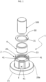
figures 1 and2 illustrate a guiding device for guiding an impact head, according to an embodiment of the invention, in two different exploded views; -
figure 3 illustrates a cross-sectional view of the guiding device offigures 2-3 , inserted in a homogenizing valve. - With reference to the figures,
reference numeral 1 denotes a guiding device for guiding animpact head 100 of a homogenizing valve 200. - In this context, an
impact head 100 is also called striking head. - The guiding
device 1 comprises asolid body 2 having a cylindrical symmetry and having aninternal cavity 3 passing through thesolid body 2. Theinternal cavity 3 develops according to an axis of symmetry A-A of thesolid body 2. - In particular, the
internal cavity 3 is coaxial with thesolid body 2. Preferably, thesolid body 2 is made of a single piece. - For example, the
solid body 2 is made of steel. - Alternatively, the
solid body 2 is made of a metal material. - The guiding
device 1 further comprises asleeve 9 fitted within theinternal cavity 3 of thesolid body 2 for receiving theimpact head 100. - The
sleeve 9 is made by a plastic material. - In particular, the
sleeve 9 is made by PTFE. - The
solid body 2 has a plurality ofpassages 4 that are obtained for allowing the passage of a fluid. - The
passages 4 aregrooves 41 obtained in thesolid body 2. - In this context, the
grooves 41 are blind apertures. - The
solid body 2 comprises afirst element 21 and asecond element 22 that are integrally connected and coaxial. - Preferably, the
first element 21 and thesecond element 22 have a substantially hollow cylindrical shape. - They are coaxial according to the axis of symmetry A-A of the
solid body 2. - In particular, the
second element 22 originates from thefirst element 21. Thefirst element 21 has an external diameter that is higher than the external diameter of thesecond element 22. - Preferably, the
first element 21 and thesecond element 22 are connected by anannular step 28a that is defined by narrowing of the diameter passing from thefirst element 21 to thesecond element 22. - The
grooves 41 are obtained in thesecond element 22 of thesolid body 2. In particular, thegrooves 41 are obtained on an external lateral surface of thesecond element 22. - Preferably, the
grooves 41 are equally spaced according to a circumferential development of thesecond element 22. - For example, the
grooves 41 are four. - The
solid body 2 has an internalannular protrusion 10 so as to retain thesleeve 9 at one end. - The
annular protrusion 10 of thesolid body 2 projects inward towards thecavity 3. - Preferably, the guiding
device 1 further comprises astop element 30 operatively active on another end of thesleeve 9 that is opposite to the end close to theprotrusion 10. - The
stop element 30 is used to maintain thesleeve 9 fitted inside thecavity 3 of thesolid body 2. - The
stop element 30 is inserted inside an internalannular groove 23 obtained in thesecond element 22. - Preferably, the
stop element 30 is a seeger. - The
seeger 30 is an annular stop element with acut 31, that is preferably made of an elastic material. For example, theseeger 30 is made of plastic, in particular PEEK. - The
seeger 30 may be fitted easily inside the internalannular groove 23 due to its elasticity and the presence of thecut 31. Number 200 identifies a homogenizing valve comprising a valve body 201 defining a through-hole having axial development with respect to the valve body 201. - The homogenizing valve 200 comprises a shaft 203 housed in the through-hole defined by the valve body 201.
- The homogenizing valve 200 has a gap wherein a fluid to be homogenized is accelerated.
- The gap is defined by a
passage head 202 that is integrally connected to the valve body 201 and animpact head 100 that is integrally connected to the shaft 203. - The homogenizing valve 200 has an inlet for a fluid at high pressure and an outlet for homogenized fluid at low pressure.
- The homogenizing valve 200 comprises a guiding
device 1 according to the proposed invention. - According to one aspect of the invention, the
solid body 2 of the guidingdevice 1 has a recess for supporting the valve body 201. - In particular, the valve body 201 urges on the
annular step 28a of thesolid body 2. - The
impact head 100 is received by thesleeve 9 of the guidingdevice 1. Theimpact head 100 is actuated by a shaft 203 that is integrally connected to theimpact head 100. - In particular, the shaft 203 is located in an upper part of the homogenizing valve 200.
- Under the pushing action of the shaft 203, the
impact head 100 is moved downwards, that means towards the gap that receives the fluid from the inlet and delivers it to the outlet. - The
impact head 100, being fitted inside thesleeve 9 is guided towards thepassage head 202. - The guiding
device 1 allows the passage of the fluid thanks to thepassages 4, that are thegrooves 41. - According to an aspect of the invention, the
impact head 100 is made of one of the following materials: tungsten carbide, ceramic, boron nitride, silicon carbide, silicon nitride. - The characteristics of the guiding device for guiding an impact head and of a homogenizing valve comprising said guiding device according to the present invention emerge clearly from the above description, as do the advantages.
- In particular, the guiding device is designed to guide the impact head by embracing it, thus reducing tolerances and misalignments.
- In addition, the impact head may be actuated in a more accurate and reliable way since the guiding device acts on the impact head close to the working area, i.e., the gap of the homogenizing valve. Providing a guiding device close to the working area is feasible thanks to the grooves that allow the passage of the fluid.
- With the claimed invention, the lifetime of the impact head is increased with respect to the known solutions.
- Furthermore, since the impact head is guided by the guiding device, it can be manufactured in material such as ceramic, boron nitride, silicon carbide, which are less hard than tungsten carbide.
Claims (8)
- A guiding device (1) for guiding an impact head (100) of a homogenizing valve (200), said guiding device (1) comprising:- a solid body (2) having a cylindrical symmetry and having an internal cavity (3) passing through the solid body (2), said internal cavity (3) developing according to an axis of symmetry (A-A) of the solid body (2), said solid body (2) having a plurality of passages (4) that are obtained for allowing the passage of a fluid;- a sleeve (9) fitted within the internal cavity (3) of the solid body (2) for receiving the impact head (100),characterized in that the passages of said plurality of passages (4) are grooves (41) obtained in the solid body (2).
- The guiding device (1) according to claim 1, wherein the solid body (2) is made of a single piece.
- The guiding device (1) according to claim 1 or 2, wherein the solid body (2) comprises a first element (21) and a second element (22) that are integrally connected and coaxial, the second element (22) originating from the first element (21), said grooves (41) being obtained in the second element (22).
- The guiding device (1) according to claim 3, wherein said second element (22) has a cylindrical symmetry, said grooves (41) being obtained on an external lateral surface of the second element (22).
- The guiding device (1) according to claim 4, further comprising a stop element (30) operatively active on said sleeve (9) for maintaining it fitted within the internal cavity (3) of the solid body (2), the second element (22) having an internal annular groove (23) for receiving said stop element (30).
- The guiding device (1) according to claim 5, wherein the stop element (30) is a seeger.
- A homogenizing valve (200) comprising:- a valve body (201) defining a through-hole having axial development with respect to the valve body (201);- a shaft (203) housed in said through-hole;- a passage head (202) integrally connected to the valve body (201);- an impact head (100) integrally connected to the shaft (203);- a gap defined by the passage head (202) and the impact head (100);- a guiding device (1) according to any one of the preceding claims, said impact head (100) being received by the sleeve (9) of said guiding device (1).
- The homogenizing valve (200) according to claim 7, wherein said impact head (100) is made of one of the following materials: tungsten carbide, ceramic, boron nitride, silicon carbide, silicon nitride.
Priority Applications (1)
| Application Number | Priority Date | Filing Date | Title |
|---|---|---|---|
| HRP20250436TT HRP20250436T1 (en) | 2022-11-16 | 2023-08-24 | GUIDING DEVICE FOR GUIDING THE IMPACT HEAD AND HOMOGENIZING VALVE CONTAINING THE SAID GUIDE DEVICE |
Applications Claiming Priority (3)
| Application Number | Priority Date | Filing Date | Title |
|---|---|---|---|
| IT102022000023643A IT202200023643A1 (en) | 2022-11-16 | 2022-11-16 | A GUIDING DEVICE FOR GUIDING AN IMPACT HEAD AND A HOMOGENIZING VALVE COMPRISING SAID GUIDING DEVICE |
| PCT/IB2023/058407 WO2024105463A1 (en) | 2022-11-16 | 2023-08-24 | A guiding device for guiding an impact head and a homogenizing valve comprising said guiding device |
| EP23764400.0A EP4392171B1 (en) | 2022-11-16 | 2023-08-24 | A guiding device for guiding an impact head and a homogenizing valve comprising said guiding device |
Related Parent Applications (2)
| Application Number | Title | Priority Date | Filing Date |
|---|---|---|---|
| EP23764400.0A Division-Into EP4392171B1 (en) | 2022-11-16 | 2023-08-24 | A guiding device for guiding an impact head and a homogenizing valve comprising said guiding device |
| EP23764400.0A Division EP4392171B1 (en) | 2022-11-16 | 2023-08-24 | A guiding device for guiding an impact head and a homogenizing valve comprising said guiding device |
Publications (3)
| Publication Number | Publication Date |
|---|---|
| EP4454742A1 EP4454742A1 (en) | 2024-10-30 |
| EP4454742C0 EP4454742C0 (en) | 2025-04-02 |
| EP4454742B1 true EP4454742B1 (en) | 2025-04-02 |
Family
ID=91070421
Family Applications (2)
| Application Number | Title | Priority Date | Filing Date |
|---|---|---|---|
| EP23764400.0A Active EP4392171B1 (en) | 2022-11-16 | 2023-08-24 | A guiding device for guiding an impact head and a homogenizing valve comprising said guiding device |
| EP24177463.7A Active EP4454742B1 (en) | 2022-11-16 | 2023-08-24 | A guiding device for guiding an impact head and a homogenizing valve comprising said guiding device |
Family Applications Before (1)
| Application Number | Title | Priority Date | Filing Date |
|---|---|---|---|
| EP23764400.0A Active EP4392171B1 (en) | 2022-11-16 | 2023-08-24 | A guiding device for guiding an impact head and a homogenizing valve comprising said guiding device |
Country Status (8)
| Country | Link |
|---|---|
| EP (2) | EP4392171B1 (en) |
| JP (1) | JP2025540545A (en) |
| KR (1) | KR20250078793A (en) |
| CN (1) | CN118354839A (en) |
| AU (1) | AU2023343802A1 (en) |
| CA (1) | CA3237689A1 (en) |
| ES (1) | ES3021185T3 (en) |
| HR (1) | HRP20250434T1 (en) |
Family Cites Families (6)
| Publication number | Priority date | Publication date | Assignee | Title |
|---|---|---|---|---|
| US1509453A (en) * | 1923-02-19 | 1924-09-23 | Trudel Francois Xavier Ovide | Homogenizer for liquids |
| JPS621444A (en) * | 1985-06-27 | 1987-01-07 | Snow Brand Milk Prod Co Ltd | High pressure type homogenizer |
| IT1282765B1 (en) | 1996-05-30 | 1998-03-31 | Niro Soavi Spa | HOMOGENIZATION VALVE |
| IT1393851B1 (en) * | 2009-04-01 | 2012-05-11 | Bertoli S R L | HOMOGENIZATION VALVE |
| IT201800010845A1 (en) * | 2018-12-05 | 2020-06-05 | Gea Mech Equipment Italia S P A | HIGH PRESSURE HOMOGENIZING VALVE AND PRODUCTION PROCESS OF CARBON-BASED NANOSTRUCTURED MATERIALS, IN PARTICULAR GRAPHENE AND CARBON NANOTUBES |
| IT202000007159A1 (en) * | 2020-04-03 | 2021-10-03 | Gea Mech Equipment Italia S P A | VALIDATION METHOD OF A HOMOGENIZING VALVE |
-
2023
- 2023-08-24 HR HRP20250434TT patent/HRP20250434T1/en unknown
- 2023-08-24 KR KR1020247015813A patent/KR20250078793A/en active Pending
- 2023-08-24 JP JP2024522108A patent/JP2025540545A/en active Pending
- 2023-08-24 EP EP23764400.0A patent/EP4392171B1/en active Active
- 2023-08-24 ES ES23764400T patent/ES3021185T3/en active Active
- 2023-08-24 EP EP24177463.7A patent/EP4454742B1/en active Active
- 2023-08-24 CN CN202380014408.1A patent/CN118354839A/en active Pending
- 2023-08-24 AU AU2023343802A patent/AU2023343802A1/en active Pending
- 2023-08-24 CA CA3237689A patent/CA3237689A1/en active Pending
Also Published As
| Publication number | Publication date |
|---|---|
| CN118354839A (en) | 2024-07-16 |
| HRP20250434T1 (en) | 2025-06-20 |
| EP4392171C0 (en) | 2025-03-26 |
| EP4454742C0 (en) | 2025-04-02 |
| EP4392171B1 (en) | 2025-03-26 |
| JP2025540545A (en) | 2025-12-16 |
| KR20250078793A (en) | 2025-06-04 |
| ES3021185T3 (en) | 2025-05-26 |
| AU2023343802A1 (en) | 2024-05-30 |
| EP4454742A1 (en) | 2024-10-30 |
| CA3237689A1 (en) | 2024-05-16 |
| EP4392171A1 (en) | 2024-07-03 |
Similar Documents
| Publication | Publication Date | Title |
|---|---|---|
| EP2411711B1 (en) | Flow rate control valve and assembly method therefor | |
| EP4454742A1 (en) | A guiding device for guiding an impact head and a homogenizing valve comprising said guiding device | |
| US5277403A (en) | Balanced, steam control valve assembly, and a plug-type valving element therefor | |
| WO2024105463A1 (en) | A guiding device for guiding an impact head and a homogenizing valve comprising said guiding device | |
| RU2833958C1 (en) | Guide device for guiding impact head and homogenizing valve comprising said guide device | |
| AU2022330596B2 (en) | Valve | |
| US20100296363A1 (en) | Homogenizing valve | |
| CN105275694B (en) | Flow restricting passage in common rail injector | |
| EP1762723B1 (en) | Injection valve and method of making orifice | |
| CN109715947B (en) | Valve, in particular pump valve for delivering abrasive and/or heterogeneous mixtures | |
| EP4479168B1 (en) | CARTRIDGE AND HOMOGENIZING VALVE WITH THE CARTRIDGE | |
| WO2025104563A1 (en) | A guiding device for use in a homogenizing valve and a homogenizing valve comprising said guiding device | |
| CN111664255B (en) | Flow rate regulating valve and assembling method thereof | |
| JP6534803B2 (en) | Fluid control valve | |
| WO2014057886A1 (en) | Hydraulic cylinder | |
| AU2023426268B2 (en) | Multi-gap valve and homogenizing apparatus comprising said multi-gap valve | |
| CN113302424B (en) | Electromagnetic valve for gas | |
| CN101978198B (en) | Valve | |
| CN120212299A (en) | A control valve | |
| JP2021177086A (en) | Gas fuel regulator |
Legal Events
| Date | Code | Title | Description |
|---|---|---|---|
| PUAI | Public reference made under article 153(3) epc to a published international application that has entered the european phase |
Free format text: ORIGINAL CODE: 0009012 |
|
| STAA | Information on the status of an ep patent application or granted ep patent |
Free format text: STATUS: THE APPLICATION HAS BEEN PUBLISHED |
|
| AC | Divisional application: reference to earlier application |
Ref document number: 4392171 Country of ref document: EP Kind code of ref document: P |
|
| AK | Designated contracting states |
Kind code of ref document: A1 Designated state(s): AL AT BE BG CH CY CZ DE DK EE ES FI FR GB GR HR HU IE IS IT LI LT LU LV MC ME MK MT NL NO PL PT RO RS SE SI SK SM TR |
|
| STAA | Information on the status of an ep patent application or granted ep patent |
Free format text: STATUS: REQUEST FOR EXAMINATION WAS MADE |
|
| 17P | Request for examination filed |
Effective date: 20241118 |
|
| RBV | Designated contracting states (corrected) |
Designated state(s): AL AT BE BG CH CY CZ DE DK EE ES FI FR GB GR HR HU IE IS IT LI LT LU LV MC ME MK MT NL NO PL PT RO RS SE SI SK SM TR |
|
| GRAP | Despatch of communication of intention to grant a patent |
Free format text: ORIGINAL CODE: EPIDOSNIGR1 |
|
| STAA | Information on the status of an ep patent application or granted ep patent |
Free format text: STATUS: GRANT OF PATENT IS INTENDED |
|
| GRAS | Grant fee paid |
Free format text: ORIGINAL CODE: EPIDOSNIGR3 |
|
| GRAA | (expected) grant |
Free format text: ORIGINAL CODE: 0009210 |
|
| STAA | Information on the status of an ep patent application or granted ep patent |
Free format text: STATUS: THE PATENT HAS BEEN GRANTED |
|
| INTG | Intention to grant announced |
Effective date: 20250212 |
|
| AC | Divisional application: reference to earlier application |
Ref document number: 4392171 Country of ref document: EP Kind code of ref document: P |
|
| AK | Designated contracting states |
Kind code of ref document: B1 Designated state(s): AL AT BE BG CH CY CZ DE DK EE ES FI FR GB GR HR HU IE IS IT LI LT LU LV MC ME MK MT NL NO PL PT RO RS SE SI SK SM TR |
|
| REG | Reference to a national code |
Ref country code: GB Ref legal event code: FG4D |
|
| REG | Reference to a national code |
Ref country code: CH Ref legal event code: EP |
|
| REG | Reference to a national code |
Ref country code: IE Ref legal event code: FG4D |
|
| U01 | Request for unitary effect filed |
Effective date: 20250408 |
|
| U07 | Unitary effect registered |
Designated state(s): AT BE BG DE DK EE FI FR IT LT LU LV MT NL PT RO SE SI Effective date: 20250415 |
|
| REG | Reference to a national code |
Ref country code: ES Ref legal event code: FG2A Ref document number: 3023844 Country of ref document: ES Kind code of ref document: T3 Effective date: 20250603 |
|
| REG | Reference to a national code |
Ref country code: HR Ref legal event code: T1PR Ref document number: P20250436 Country of ref document: HR |
|
| REG | Reference to a national code |
Ref country code: GR Ref legal event code: EP Ref document number: 20250401125 Country of ref document: GR Effective date: 20250707 |
|
| U20 | Renewal fee for the european patent with unitary effect paid |
Year of fee payment: 3 Effective date: 20250806 |
|
| REG | Reference to a national code |
Ref country code: HR Ref legal event code: ODRP Ref document number: P20250436 Country of ref document: HR Payment date: 20250806 Year of fee payment: 3 |
|
| PGFP | Annual fee paid to national office [announced via postgrant information from national office to epo] |
Ref country code: ES Payment date: 20250916 Year of fee payment: 3 |
|
| PGFP | Annual fee paid to national office [announced via postgrant information from national office to epo] |
Ref country code: NO Payment date: 20250819 Year of fee payment: 3 Ref country code: GR Payment date: 20250820 Year of fee payment: 3 |
|
| PG25 | Lapsed in a contracting state [announced via postgrant information from national office to epo] |
Ref country code: PL Free format text: LAPSE BECAUSE OF FAILURE TO SUBMIT A TRANSLATION OF THE DESCRIPTION OR TO PAY THE FEE WITHIN THE PRESCRIBED TIME-LIMIT Effective date: 20250402 |
|
| PGFP | Annual fee paid to national office [announced via postgrant information from national office to epo] |
Ref country code: HR Payment date: 20250806 Year of fee payment: 3 |
|
| PG25 | Lapsed in a contracting state [announced via postgrant information from national office to epo] |
Ref country code: RS Free format text: LAPSE BECAUSE OF FAILURE TO SUBMIT A TRANSLATION OF THE DESCRIPTION OR TO PAY THE FEE WITHIN THE PRESCRIBED TIME-LIMIT Effective date: 20250702 |
|
| PG25 | Lapsed in a contracting state [announced via postgrant information from national office to epo] |
Ref country code: IS Free format text: LAPSE BECAUSE OF FAILURE TO SUBMIT A TRANSLATION OF THE DESCRIPTION OR TO PAY THE FEE WITHIN THE PRESCRIBED TIME-LIMIT Effective date: 20250802 |
|
| PG25 | Lapsed in a contracting state [announced via postgrant information from national office to epo] |
Ref country code: SM Free format text: LAPSE BECAUSE OF FAILURE TO SUBMIT A TRANSLATION OF THE DESCRIPTION OR TO PAY THE FEE WITHIN THE PRESCRIBED TIME-LIMIT Effective date: 20250402 |
|
| PG25 | Lapsed in a contracting state [announced via postgrant information from national office to epo] |
Ref country code: CZ Free format text: LAPSE BECAUSE OF FAILURE TO SUBMIT A TRANSLATION OF THE DESCRIPTION OR TO PAY THE FEE WITHIN THE PRESCRIBED TIME-LIMIT Effective date: 20250402 |
|
| PG25 | Lapsed in a contracting state [announced via postgrant information from national office to epo] |
Ref country code: SK Free format text: LAPSE BECAUSE OF FAILURE TO SUBMIT A TRANSLATION OF THE DESCRIPTION OR TO PAY THE FEE WITHIN THE PRESCRIBED TIME-LIMIT Effective date: 20250402 |
|
| PLBE | No opposition filed within time limit |
Free format text: ORIGINAL CODE: 0009261 |
|
| STAA | Information on the status of an ep patent application or granted ep patent |
Free format text: STATUS: NO OPPOSITION FILED WITHIN TIME LIMIT |
|
| REG | Reference to a national code |
Ref country code: CH Ref legal event code: L10 Free format text: ST27 STATUS EVENT CODE: U-0-0-L10-L00 (AS PROVIDED BY THE NATIONAL OFFICE) Effective date: 20260211 |
|
| 26N | No opposition filed |
Effective date: 20260105 |
|
| PG25 | Lapsed in a contracting state [announced via postgrant information from national office to epo] |
Ref country code: MC Free format text: LAPSE BECAUSE OF FAILURE TO SUBMIT A TRANSLATION OF THE DESCRIPTION OR TO PAY THE FEE WITHIN THE PRESCRIBED TIME-LIMIT Effective date: 20250402 |