EP4454617A1 - Tibiales probeimplantat - Google Patents
Tibiales probeimplantat Download PDFInfo
- Publication number
- EP4454617A1 EP4454617A1 EP24171006.0A EP24171006A EP4454617A1 EP 4454617 A1 EP4454617 A1 EP 4454617A1 EP 24171006 A EP24171006 A EP 24171006A EP 4454617 A1 EP4454617 A1 EP 4454617A1
- Authority
- EP
- European Patent Office
- Prior art keywords
- component
- articulation
- ramp
- support
- trial implant
- Prior art date
- Legal status (The legal status is an assumption and is not a legal conclusion. Google has not performed a legal analysis and makes no representation as to the accuracy of the status listed.)
- Pending
Links
Images




Classifications
-
- A—HUMAN NECESSITIES
- A61—MEDICAL OR VETERINARY SCIENCE; HYGIENE
- A61F—FILTERS IMPLANTABLE INTO BLOOD VESSELS; PROSTHESES; DEVICES PROVIDING PATENCY TO, OR PREVENTING COLLAPSING OF, TUBULAR STRUCTURES OF THE BODY, e.g. STENTS; ORTHOPAEDIC, NURSING OR CONTRACEPTIVE DEVICES; FOMENTATION; TREATMENT OR PROTECTION OF EYES OR EARS; BANDAGES, DRESSINGS OR ABSORBENT PADS; FIRST-AID KITS
- A61F2/00—Filters implantable into blood vessels; Prostheses, i.e. artificial substitutes or replacements for parts of the body; Appliances for connecting them with the body; Devices providing patency to, or preventing collapsing of, tubular structures of the body, e.g. stents
- A61F2/02—Prostheses implantable into the body
- A61F2/30—Joints
- A61F2/46—Special tools for implanting artificial joints
- A61F2/4684—Trial or dummy prostheses
-
- A—HUMAN NECESSITIES
- A61—MEDICAL OR VETERINARY SCIENCE; HYGIENE
- A61F—FILTERS IMPLANTABLE INTO BLOOD VESSELS; PROSTHESES; DEVICES PROVIDING PATENCY TO, OR PREVENTING COLLAPSING OF, TUBULAR STRUCTURES OF THE BODY, e.g. STENTS; ORTHOPAEDIC, NURSING OR CONTRACEPTIVE DEVICES; FOMENTATION; TREATMENT OR PROTECTION OF EYES OR EARS; BANDAGES, DRESSINGS OR ABSORBENT PADS; FIRST-AID KITS
- A61F2/00—Filters implantable into blood vessels; Prostheses, i.e. artificial substitutes or replacements for parts of the body; Appliances for connecting them with the body; Devices providing patency to, or preventing collapsing of, tubular structures of the body, e.g. stents
- A61F2/02—Prostheses implantable into the body
- A61F2/30—Joints
- A61F2/38—Joints for elbows or knees
- A61F2/3859—Femoral components
-
- A—HUMAN NECESSITIES
- A61—MEDICAL OR VETERINARY SCIENCE; HYGIENE
- A61F—FILTERS IMPLANTABLE INTO BLOOD VESSELS; PROSTHESES; DEVICES PROVIDING PATENCY TO, OR PREVENTING COLLAPSING OF, TUBULAR STRUCTURES OF THE BODY, e.g. STENTS; ORTHOPAEDIC, NURSING OR CONTRACEPTIVE DEVICES; FOMENTATION; TREATMENT OR PROTECTION OF EYES OR EARS; BANDAGES, DRESSINGS OR ABSORBENT PADS; FIRST-AID KITS
- A61F2/00—Filters implantable into blood vessels; Prostheses, i.e. artificial substitutes or replacements for parts of the body; Appliances for connecting them with the body; Devices providing patency to, or preventing collapsing of, tubular structures of the body, e.g. stents
- A61F2/02—Prostheses implantable into the body
- A61F2/30—Joints
- A61F2/38—Joints for elbows or knees
- A61F2/389—Tibial components
-
- B—PERFORMING OPERATIONS; TRANSPORTING
- B33—ADDITIVE MANUFACTURING TECHNOLOGY
- B33Y—ADDITIVE MANUFACTURING, i.e. MANUFACTURING OF THREE-DIMENSIONAL [3D] OBJECTS BY ADDITIVE DEPOSITION, ADDITIVE AGGLOMERATION OR ADDITIVE LAYERING, e.g. BY 3D PRINTING, STEREOLITHOGRAPHY OR SELECTIVE LASER SINTERING
- B33Y80/00—Products made by additive manufacturing
-
- A—HUMAN NECESSITIES
- A61—MEDICAL OR VETERINARY SCIENCE; HYGIENE
- A61F—FILTERS IMPLANTABLE INTO BLOOD VESSELS; PROSTHESES; DEVICES PROVIDING PATENCY TO, OR PREVENTING COLLAPSING OF, TUBULAR STRUCTURES OF THE BODY, e.g. STENTS; ORTHOPAEDIC, NURSING OR CONTRACEPTIVE DEVICES; FOMENTATION; TREATMENT OR PROTECTION OF EYES OR EARS; BANDAGES, DRESSINGS OR ABSORBENT PADS; FIRST-AID KITS
- A61F2/00—Filters implantable into blood vessels; Prostheses, i.e. artificial substitutes or replacements for parts of the body; Appliances for connecting them with the body; Devices providing patency to, or preventing collapsing of, tubular structures of the body, e.g. stents
- A61F2/02—Prostheses implantable into the body
- A61F2/30—Joints
- A61F2/38—Joints for elbows or knees
-
- A—HUMAN NECESSITIES
- A61—MEDICAL OR VETERINARY SCIENCE; HYGIENE
- A61F—FILTERS IMPLANTABLE INTO BLOOD VESSELS; PROSTHESES; DEVICES PROVIDING PATENCY TO, OR PREVENTING COLLAPSING OF, TUBULAR STRUCTURES OF THE BODY, e.g. STENTS; ORTHOPAEDIC, NURSING OR CONTRACEPTIVE DEVICES; FOMENTATION; TREATMENT OR PROTECTION OF EYES OR EARS; BANDAGES, DRESSINGS OR ABSORBENT PADS; FIRST-AID KITS
- A61F2/00—Filters implantable into blood vessels; Prostheses, i.e. artificial substitutes or replacements for parts of the body; Appliances for connecting them with the body; Devices providing patency to, or preventing collapsing of, tubular structures of the body, e.g. stents
- A61F2/02—Prostheses implantable into the body
- A61F2/30—Joints
- A61F2002/30001—Additional features of subject-matter classified in A61F2/28, A61F2/30 and subgroups thereof
- A61F2002/30108—Shapes
- A61F2002/3011—Cross-sections or two-dimensional shapes
- A61F2002/30112—Rounded shapes, e.g. with rounded corners
- A61F2002/30131—Rounded shapes, e.g. with rounded corners horseshoe- or crescent- or C-shaped or U-shaped
-
- A—HUMAN NECESSITIES
- A61—MEDICAL OR VETERINARY SCIENCE; HYGIENE
- A61F—FILTERS IMPLANTABLE INTO BLOOD VESSELS; PROSTHESES; DEVICES PROVIDING PATENCY TO, OR PREVENTING COLLAPSING OF, TUBULAR STRUCTURES OF THE BODY, e.g. STENTS; ORTHOPAEDIC, NURSING OR CONTRACEPTIVE DEVICES; FOMENTATION; TREATMENT OR PROTECTION OF EYES OR EARS; BANDAGES, DRESSINGS OR ABSORBENT PADS; FIRST-AID KITS
- A61F2/00—Filters implantable into blood vessels; Prostheses, i.e. artificial substitutes or replacements for parts of the body; Appliances for connecting them with the body; Devices providing patency to, or preventing collapsing of, tubular structures of the body, e.g. stents
- A61F2/02—Prostheses implantable into the body
- A61F2/30—Joints
- A61F2002/30001—Additional features of subject-matter classified in A61F2/28, A61F2/30 and subgroups thereof
- A61F2002/30108—Shapes
- A61F2002/30199—Three-dimensional shapes
- A61F2002/30261—Three-dimensional shapes parallelepipedal
- A61F2002/30266—Three-dimensional shapes parallelepipedal wedge-shaped parallelepipeds
-
- A—HUMAN NECESSITIES
- A61—MEDICAL OR VETERINARY SCIENCE; HYGIENE
- A61F—FILTERS IMPLANTABLE INTO BLOOD VESSELS; PROSTHESES; DEVICES PROVIDING PATENCY TO, OR PREVENTING COLLAPSING OF, TUBULAR STRUCTURES OF THE BODY, e.g. STENTS; ORTHOPAEDIC, NURSING OR CONTRACEPTIVE DEVICES; FOMENTATION; TREATMENT OR PROTECTION OF EYES OR EARS; BANDAGES, DRESSINGS OR ABSORBENT PADS; FIRST-AID KITS
- A61F2/00—Filters implantable into blood vessels; Prostheses, i.e. artificial substitutes or replacements for parts of the body; Appliances for connecting them with the body; Devices providing patency to, or preventing collapsing of, tubular structures of the body, e.g. stents
- A61F2/02—Prostheses implantable into the body
- A61F2/30—Joints
- A61F2002/30001—Additional features of subject-matter classified in A61F2/28, A61F2/30 and subgroups thereof
- A61F2002/30316—The prosthesis having different structural features at different locations within the same prosthesis; Connections between prosthetic parts; Special structural features of bone or joint prostheses not otherwise provided for
- A61F2002/30329—Connections or couplings between prosthetic parts, e.g. between modular parts; Connecting elements
- A61F2002/30383—Connections or couplings between prosthetic parts, e.g. between modular parts; Connecting elements made by laterally inserting a protrusion, e.g. a rib into a complementarily-shaped groove
- A61F2002/3039—Connections or couplings between prosthetic parts, e.g. between modular parts; Connecting elements made by laterally inserting a protrusion, e.g. a rib into a complementarily-shaped groove with possibility of relative movement of the rib within the groove
- A61F2002/30398—Sliding
-
- A—HUMAN NECESSITIES
- A61—MEDICAL OR VETERINARY SCIENCE; HYGIENE
- A61F—FILTERS IMPLANTABLE INTO BLOOD VESSELS; PROSTHESES; DEVICES PROVIDING PATENCY TO, OR PREVENTING COLLAPSING OF, TUBULAR STRUCTURES OF THE BODY, e.g. STENTS; ORTHOPAEDIC, NURSING OR CONTRACEPTIVE DEVICES; FOMENTATION; TREATMENT OR PROTECTION OF EYES OR EARS; BANDAGES, DRESSINGS OR ABSORBENT PADS; FIRST-AID KITS
- A61F2/00—Filters implantable into blood vessels; Prostheses, i.e. artificial substitutes or replacements for parts of the body; Appliances for connecting them with the body; Devices providing patency to, or preventing collapsing of, tubular structures of the body, e.g. stents
- A61F2/02—Prostheses implantable into the body
- A61F2/30—Joints
- A61F2002/30001—Additional features of subject-matter classified in A61F2/28, A61F2/30 and subgroups thereof
- A61F2002/30316—The prosthesis having different structural features at different locations within the same prosthesis; Connections between prosthetic parts; Special structural features of bone or joint prostheses not otherwise provided for
- A61F2002/30329—Connections or couplings between prosthetic parts, e.g. between modular parts; Connecting elements
- A61F2002/30383—Connections or couplings between prosthetic parts, e.g. between modular parts; Connecting elements made by laterally inserting a protrusion, e.g. a rib into a complementarily-shaped groove
- A61F2002/3039—Connections or couplings between prosthetic parts, e.g. between modular parts; Connecting elements made by laterally inserting a protrusion, e.g. a rib into a complementarily-shaped groove with possibility of relative movement of the rib within the groove
- A61F2002/30398—Sliding
- A61F2002/304—Sliding with additional means for limiting said sliding
-
- A—HUMAN NECESSITIES
- A61—MEDICAL OR VETERINARY SCIENCE; HYGIENE
- A61F—FILTERS IMPLANTABLE INTO BLOOD VESSELS; PROSTHESES; DEVICES PROVIDING PATENCY TO, OR PREVENTING COLLAPSING OF, TUBULAR STRUCTURES OF THE BODY, e.g. STENTS; ORTHOPAEDIC, NURSING OR CONTRACEPTIVE DEVICES; FOMENTATION; TREATMENT OR PROTECTION OF EYES OR EARS; BANDAGES, DRESSINGS OR ABSORBENT PADS; FIRST-AID KITS
- A61F2/00—Filters implantable into blood vessels; Prostheses, i.e. artificial substitutes or replacements for parts of the body; Appliances for connecting them with the body; Devices providing patency to, or preventing collapsing of, tubular structures of the body, e.g. stents
- A61F2/02—Prostheses implantable into the body
- A61F2/30—Joints
- A61F2002/30001—Additional features of subject-matter classified in A61F2/28, A61F2/30 and subgroups thereof
- A61F2002/30316—The prosthesis having different structural features at different locations within the same prosthesis; Connections between prosthetic parts; Special structural features of bone or joint prostheses not otherwise provided for
- A61F2002/30535—Special structural features of bone or joint prostheses not otherwise provided for
- A61F2002/30537—Special structural features of bone or joint prostheses not otherwise provided for adjustable
- A61F2002/30556—Special structural features of bone or joint prostheses not otherwise provided for adjustable for adjusting thickness
-
- A—HUMAN NECESSITIES
- A61—MEDICAL OR VETERINARY SCIENCE; HYGIENE
- A61F—FILTERS IMPLANTABLE INTO BLOOD VESSELS; PROSTHESES; DEVICES PROVIDING PATENCY TO, OR PREVENTING COLLAPSING OF, TUBULAR STRUCTURES OF THE BODY, e.g. STENTS; ORTHOPAEDIC, NURSING OR CONTRACEPTIVE DEVICES; FOMENTATION; TREATMENT OR PROTECTION OF EYES OR EARS; BANDAGES, DRESSINGS OR ABSORBENT PADS; FIRST-AID KITS
- A61F2/00—Filters implantable into blood vessels; Prostheses, i.e. artificial substitutes or replacements for parts of the body; Appliances for connecting them with the body; Devices providing patency to, or preventing collapsing of, tubular structures of the body, e.g. stents
- A61F2/02—Prostheses implantable into the body
- A61F2/30—Joints
- A61F2002/30001—Additional features of subject-matter classified in A61F2/28, A61F2/30 and subgroups thereof
- A61F2002/30667—Features concerning an interaction with the environment or a particular use of the prosthesis
- A61F2002/30672—Features concerning an interaction with the environment or a particular use of the prosthesis temporary
-
- A—HUMAN NECESSITIES
- A61—MEDICAL OR VETERINARY SCIENCE; HYGIENE
- A61F—FILTERS IMPLANTABLE INTO BLOOD VESSELS; PROSTHESES; DEVICES PROVIDING PATENCY TO, OR PREVENTING COLLAPSING OF, TUBULAR STRUCTURES OF THE BODY, e.g. STENTS; ORTHOPAEDIC, NURSING OR CONTRACEPTIVE DEVICES; FOMENTATION; TREATMENT OR PROTECTION OF EYES OR EARS; BANDAGES, DRESSINGS OR ABSORBENT PADS; FIRST-AID KITS
- A61F2/00—Filters implantable into blood vessels; Prostheses, i.e. artificial substitutes or replacements for parts of the body; Appliances for connecting them with the body; Devices providing patency to, or preventing collapsing of, tubular structures of the body, e.g. stents
- A61F2/02—Prostheses implantable into the body
- A61F2/30—Joints
- A61F2/3094—Designing or manufacturing processes
- A61F2002/30985—Designing or manufacturing processes using three dimensional printing [3DP]
-
- A—HUMAN NECESSITIES
- A61—MEDICAL OR VETERINARY SCIENCE; HYGIENE
- A61F—FILTERS IMPLANTABLE INTO BLOOD VESSELS; PROSTHESES; DEVICES PROVIDING PATENCY TO, OR PREVENTING COLLAPSING OF, TUBULAR STRUCTURES OF THE BODY, e.g. STENTS; ORTHOPAEDIC, NURSING OR CONTRACEPTIVE DEVICES; FOMENTATION; TREATMENT OR PROTECTION OF EYES OR EARS; BANDAGES, DRESSINGS OR ABSORBENT PADS; FIRST-AID KITS
- A61F2/00—Filters implantable into blood vessels; Prostheses, i.e. artificial substitutes or replacements for parts of the body; Appliances for connecting them with the body; Devices providing patency to, or preventing collapsing of, tubular structures of the body, e.g. stents
- A61F2/02—Prostheses implantable into the body
- A61F2/30—Joints
- A61F2/46—Special tools for implanting artificial joints
- A61F2/4603—Special tools for implanting artificial joints for insertion or extraction of endoprosthetic joints or of accessories thereof
- A61F2002/4625—Special tools for implanting artificial joints for insertion or extraction of endoprosthetic joints or of accessories thereof with relative movement between parts of the instrument during use
-
- A—HUMAN NECESSITIES
- A61—MEDICAL OR VETERINARY SCIENCE; HYGIENE
- A61F—FILTERS IMPLANTABLE INTO BLOOD VESSELS; PROSTHESES; DEVICES PROVIDING PATENCY TO, OR PREVENTING COLLAPSING OF, TUBULAR STRUCTURES OF THE BODY, e.g. STENTS; ORTHOPAEDIC, NURSING OR CONTRACEPTIVE DEVICES; FOMENTATION; TREATMENT OR PROTECTION OF EYES OR EARS; BANDAGES, DRESSINGS OR ABSORBENT PADS; FIRST-AID KITS
- A61F2/00—Filters implantable into blood vessels; Prostheses, i.e. artificial substitutes or replacements for parts of the body; Appliances for connecting them with the body; Devices providing patency to, or preventing collapsing of, tubular structures of the body, e.g. stents
- A61F2/02—Prostheses implantable into the body
- A61F2/30—Joints
- A61F2/46—Special tools for implanting artificial joints
- A61F2/4657—Measuring instruments used for implanting artificial joints
- A61F2002/4658—Measuring instruments used for implanting artificial joints for measuring dimensions, e.g. length
- A61F2002/4661—Measuring instruments used for implanting artificial joints for measuring dimensions, e.g. length for measuring thickness
Definitions
- the invention relates to a tibial trial implant for use in knee replacement surgery.
- Knee joint prostheses usually comprise a femoral implant, a tibial implant and a meniscus component, which is often also referred to as the sliding surface.
- the femoral implant is implanted at the distal end of the femur.
- the tibial implant is implanted at the proximal end of the tibia.
- the meniscus component is arranged proximodistal between the tibial and femoral implants.
- the implants in question must be precisely positioned in a defined manner in terms of their position and orientation in relation to the patient's body axes. In addition to precise positioning, it is important that the implants are selected and implanted with dimensions that are suitable for the patient's anatomy. With regard to the meniscus component, its proximodistal height is a particularly important criterion.
- the tibial trial implant is used to determine the required proximodistal height of the meniscus component to be implanted intraoperatively.
- the tibial trial implant is used to test the optimal ligament tension and joint line when a femoral implant has already been implanted.
- the meniscus component is selected and implanted.
- the said test can be carried out, for example, using different meniscus trial components with different defined heights.
- a tibial trial implant with an upper plate and a lower plate is known.
- the upper plate has a proximal articulation surface for articulation with a femoral component.
- the lower plate has a distal bearing surface for bearing on a tibial plateau.
- a height adjustment mechanism is arranged between the upper plate and the lower plate. The height adjustment mechanism is used to adjust a proximodistal distance between the articulation surface of the upper plate and the bearing surface of the lower plate and thus the proximodistal height of the trial implant.
- the height adjustment mechanism has two scissor joint mechanisms coupled to one another.
- the known tibial trial implant has an upper part with a proximally arranged sliding surface for sliding interaction with a femoral component.
- the lower part is intended for tibial fixation.
- a height adjustment mechanism is arranged between the upper part and the lower part, by means of which the upper part can be displaced in a vertical direction relative to the lower part. The displacement of the upper part in turn serves to adjust the said proximodistal distance and thus the height of the trial implant.
- the height adjustment mechanism has a cam gear with a rotating drive wheel.
- This trial implant has a bearing component with a proximal articulation surface and a distal surface.
- a plate component with a proximal surface and a distal attachment surface.
- a distance adjustment arrangement is arranged between the bearing component and the plate component, which on the one hand releasably engages with the bearing component and on the other hand releasably with the plate component and couples the two components together with limited mobility in the proximodistal direction.
- the known tibial trial implant also has several spacers (shims) that can be inserted into the distance adjustment arrangement between the bearing and plate components to adjust the proximodistal height. Different spacers have different proximodistal thicknesses. Depending on the selection of the spacer, a different proximodistal height of the trial implant can be set.
- the object of the invention is to provide a tibial trial implant which has a simplified structure compared to the prior art and allows easy application.
- the tibial trial implant according to the invention has an articulation component and at least one support component.
- the articulation component has a proximal articulation surface and a distal underside.
- the proximal articulation surface is designed for articulation with a femoral component.
- the at least one support component has a distal bearing surface, a proximal upper side and a guide device.
- the distal bearing surface is designed for bearing on a tibial plateau.
- the proximal upper side forms a Ramp.
- the guide device has a guide track that extends longitudinally parallel to the ramp.
- the underside of the articulation component has a support surface that is inclined parallel to the ramp.
- the articulation component is held on the guide device and is supported on the ramp with its support surface so that it can move linearly along the guide track relative to the support component.
- a relative movement between the articulation component and the support component consequently causes a change in a proximodistal distance between the articulation surface of the articulation component and the bearing surface of the support component.
- the solution according to the invention means that the tibial trial implant has a particularly simple structure. In particular, complex height adjustment mechanisms and the use of different meniscus trial components with different heights can be dispensed with. Instead, it is provided that the at least one support component can be pushed between the tibial plateau and the articulation component in the manner of a wedge.
- the top of the support component is inclined relative to the distal bearing surface and forms the said ramp.
- the distal underside of the articulation component is longitudinally extended parallel to the ramp and is therefore inclined accordingly.
- the guide device is provided to prevent undefined relative movements between the articulation component and the support component.
- the guide device fixes the articulation component and the support component to one another in a linearly movable manner along the guide track that extends parallel to the ramp - and thus also to the support surface.
- a relative movement between the articulation component and the support component along the guide track consequently causes a change in the proximodistal distance. The greater the relative movement, the greater the change in the distance.
- the support component can be inserted more or less far between the articulation component and the tibial plateau.
- the articulation component is displaced more or less proximally in the direction of the femoral component, thus changing the proximodistal distance between the bearing surface of the support component - and thus the tibial plateau - and the articulation surface.
- the femoral component and the tibial plateau are not part of the tibial trial implant.
- the femoral component can be a natural distal femur or a femoral implant component.
- the tibial plateau can be formed by a resection surface on the proximal tibia or an artificial plateau surface that is attached to the resection surface.
- the bearing surface set up for bearing on the tibial plateau is preferably flat and parallel to an anteroposterior and mediolateral transverse plane.
- the ramp formed by the top of the support component is inclined relative to the transverse plane so that, particularly when looking from a mediolateral or anteroposterior direction, a wedge-shaped shape of the support component.
- the support surface of the articulation component and the ramp slide against one another. At the same time, the two components are guided by means of the guide device.
- the guide device is arranged and/or formed on the support component at least in sections and, for the purpose of guidance, interacts with a section of the articulation component designed for this purpose.
- the tibial trial implant has exactly one support component, so that a total two-part structure is provided.
- the tibial trial implant has exactly two support components, so that a total three-part structure of the trial implant is provided.
- proximodistal means along, preferably parallel to, a proximal-distal axis
- anterior-posterior axis a proximal-distal axis
- intermediate a medial-lateral axis
- the axes in question are orthogonal to one another and can of course be set in relation to X, Y and Z axes not related to the patient's anatomy.
- the proximodistal axis can alternatively be referred to as the Z axis.
- the medio-lateral axis can be referred to as the Y-axis.
- the anterior-posterior axis can be referred to as the X-axis.
- the anatomical position and direction terms mentioned above are primarily used below.
- terms such as “top” are used in relation to a distally directed viewing direction.
- terms such as "bottom” are used in relation to a proximal directed viewing direction.
- the ramp and/or the support surface is flat and has a surface profile which is designed to prevent the articulation component from slipping off the ramp. This counteracts an unwanted change in a proximodistal distance once it has been set.
- the surface profile causes increased friction between the ramp and the support surface.
- the surface profile preferably has a surface profile in the normal direction of the ramp and/or
- the support surface has raised elevations and/or recesses.
- the flat design of the ramp and/or the support surface preferably allows a continuous change in the proximodistal distance.
- the ramp and the support surface are each provided with a sequence of steps, whereby the relative movement between the articulation component and the support component causes a gradual change in the proximodistal distance.
- the steps each have a height extending in the proximodistal direction. The steps rise from one (low) end of the ramp towards an opposite (high) end.
- the steps are each bevelled so that the support surface and the ramp - despite the presence of steps - can slide along each other along the guideway.
- the steps each have a proximodistal height of between 1 mm and 3 mm, preferably 2 mm, with at least four steps being present in each case. This results in an adjustment range of at least 4 steps for the proximodistal distance.
- a height of 2 mm for the steps has proven to be particularly advantageous. On the one hand, the height mentioned is sufficiently small to be able to adjust even small changes in the distance. On the other hand, a height of 2 mm per step with at least four steps allows a sufficiently large adjustment range overall.
- the height of the individual steps and the achievable total height of the tibial trial implant is preferably based on the available meniscus components of different heights, which are generally available in heights of 10 mm, 12 mm, 14 mm, 16 mm, 18 mm, 20 mm, 22 mm and 24 mm.
- the steps of the ramp each have a convex bulge and the steps of the support surface each have a complementary concave bulge, whereby the bulges and the bulges releasably interlock, thereby counteracting unwanted relative movement between the articulation component and the support component.
- the interlocking of the bulges and the bulges counteracts unwanted relative movements between the complementary steps and thus between the articulation component and the support component. This prevents unwanted changes in the height of the tibial trial implant.
- the engagement between the bulges and the bulges be overcome manually, for example by slightly lifting the articulation component from the support component. It is understood that an inverted arrangement of bulges and indentations can also be provided. Consequently, in one embodiment, the concave indentations are present on the steps of the ramp and the convex bulges on the steps of the support surface.
- the ramp and/or the support surface has a longitudinal inclination of 10° to 45°, preferably 15° to 30°, particularly preferably 20°.
- the longitudinal inclination is measured relative to the bearing surface and thus also to the tibial plateau.
- the longitudinal inclination is measured relative to an imaginary transverse plane. The steeper the longitudinal inclination, the greater the transmission ratio between the relative movement of the tibial and support components and the change in the proximodistal distance. A small relative movement therefore causes a relatively large change in the proximodistal distance. At the same time, a relatively large amount of force is required to advance the support component.
- a longitudinal inclination in the range of 15 to 30° has proven to be advantageous, with 20° being considered optimum.
- the ramp and the support surface are inclined longitudinally anteroposteriorly.
- the ramp rises along an anteroposterior axis, with the same applying to the support surface.
- the guideway is longitudinally extended parallel to the ramp and thus also to the support surface, the above also applies to its longitudinal inclination.
- the at least one support component is displaced anteroposteriorly relative to the articulation component in order to change the proximodistal distance.
- a relative advance of the support component directed from anterior to posterior causes an increase in the proximodistal distance.
- a reduction occurs in a kinematically opposite manner.
- the ramp and the support surface are longitudinally inclined mediolaterally.
- the ramp therefore rises along a mediolateral axis.
- the at least one support component can be displaced in the mediolateral direction relative to the articulation component for intraoperative change of the proximodistal distance.
- a "lateral" relative advance of the support component is provided. If the tibial trial implant has exactly one support component, this can be Invention can be arranged laterally or medially to a sagittal mid-longitudinal plane of the articulation component.
- a medial advancement preferably causes an increase in the proximodistal distance. If the support component is arranged medially instead, a lateral advancement preferably causes an increase in the proximodistal distance. To reduce the proximodistal distance, the support component is displaced kinematically in the opposite direction.
- two support components are present and arranged on both sides of a sagittal central longitudinal plane of the articulation component, wherein the two support components are movable mediolaterally in opposite directions relative to the articulation component to change the proximodistal distance.
- first support component is preferably arranged on a lateral side of the sagittal central longitudinal plane.
- second support component is preferably arranged on a medial side of the sagittal central longitudinal plane. To change the proximodistal distance, the two support components are moved in opposite directions relative to the articulation component.
- This embodiment allows in particular a quantitatively different change in the proximodistal distance medially and laterally.
- the articulation surface can be raised further proximally on a medial side than on a lateral side or vice versa. This allows the patient's anatomy to be taken into account in an improved manner.
- the guide device has at least one guide slot, into which at least one guide pin of the articulation component engages in a sliding manner along the guide path.
- the guide slot is introduced into the support component and defines the guide path. If the ramp and the support surface are each provided with a sequence of steps, this preferably also applies to the guide slot. In this case, the steps of the guide slot are offset parallel to the steps of the ramp.
- the at least one guide pin is arranged and/or formed on the articulation component. The guide pin engages in the guide slot in a movable manner along the guide path.
- the guide slot is open at one end and has an insertion opening for the guide pin at its open end.
- the guide pin can be inserted into the guide slot through the insertion opening.
- the guide slot is closed at its opposite ends.
- the guide pin in this embodiment can be displaced relative to the articulation component.
- additive manufacturing can be carried out in accordance with a design described in more detail below.
- two guide slots extending parallel to one another and correspondingly two guide pins are provided.
- the guide slot has an insertion opening at one end of the guide track, which, starting from the bearing surface, opens into the guide slot essentially perpendicular to the guide track and through which the at least one guide pin can be inserted into the guide slot.
- the articulation component can be attached to the support component with its articulation surface and its underside reversed, i.e. with the underside aligned approximately proximally. After inserting the at least one guide pin into the guide slot, the articulation component can be rotated by 180° so that the articulation surface and the underside return to their intended orientation.
- This special assembly or "insertion movement" means that mobility between the articulation component and the support component is only possible along the guide track. This prevents the components from being accidentally separated, particularly in the anteroposterior and/or proximodistal direction.
- the support surface is recessed proximally into the underside of the articulation component and is limited by opposing wall sections, each of which rests positively on the support component perpendicular to the guideway and perpendicular to a proximodistal axis.
- the said positive fit achieves even better guidance of the relative movement between the tibia and the support component.
- the wall sections each rest laterally on the support component, preferably the ramp.
- the articulation component has a recess extending proximodistal from the articulation surface to the support surface, which divides the articulation surface and the support surface into a medial surface section and a lateral surface section.
- the articulation surface therefore has a medial articulation surface section and a lateral articulation surface section. These two sections are arranged opposite one another on both sides of the recess and are spaced apart from one another by a mediolateral dimension of the recess. The same applies, mutatis mutandis, to the support surface, so that there is a medial support surface section and a lateral support surface section.
- the recess allows in particular improved visibility of the support component arranged distally/below the articulation component. If the support component is also provided with a recess, the tibial plateau can be viewed. This allows the surgeon to have improved intraoperative control.
- the at least one support component has a recess extending proximodistal through the ramp, which divides the ramp into two ramp sections that are spaced apart from one another laterally, in particular mediolaterally or anteroposteriorly.
- the ramp extending through the recess enables material to be saved and, as a result, manufacturing costs and weight to be reduced. If the articulation component is provided with a recess according to the previous description, the recess in the support component enables improved visibility of the tibial plateau arranged distally/underneath the support component.
- the two ramp sections are spaced apart from one another mediolaterally by the dimensions of the recess. Consequently, one can also speak of a medial and a lateral ramp section. If the ramp has a mediolateral longitudinal inclination, the two ramp sections are spaced apart from one another anteroposteriorly by the dimensions of the recess. In this case, one can also speak of an anterior ramp section and a posterior ramp section. Both ramp sections are each longitudinally extended.
- the recess is preferably open at one end in the longitudinal direction of the ramp, with the opening preferably being arranged at a low end of the ramp.
- the at least one support component has a U-shaped configuration in the proximal and/or distal viewing direction, with the two ramp sections each forming an elongated leg of the U-shape.
- the U-shape of the support component enables ergonomic handling in particular.
- the U-shaped support component can be gripped between the fingers of one hand in the area of a transverse leg connecting the two elongated legs. This is ergonomically advantageous.
- the articulation component and the at least one support component are each made of a biocompatible plastic material.
- Biocompatible plastic materials are known as such to the responsible specialist.
- the use of such plastic materials for the articulation component and the support component offers particular advantages.
- the articulation component and the at least one support component are each made in one piece from the said plastic material. Production can be carried out, for example, by means of injection molding. In a further embodiment, additive manufacturing is carried out instead.
- the articulation component and the at least one support component are manufactured additively by means of a common 3D printing process, whereby the articulation component and the at least one support component are permanently connected to one another via the guide device and are movable relative to one another.
- the articulation component and the at least one support component are fixed to one another in a captive manner. Due to the common 3D printing process, no separate assembly step is required to connect the articulation component to the at least one support component.
- the 3D printing is preferably carried out using a biocompatible plastic material.
- a tibial trial implant 1 is intended for use in a knee replacement operation.
- the tibial trial implant 1 is used to determine a proximodistal height of a tibial implant and is often referred to as a trial surface in medical terminology.
- the tibial trial implant 1 has an articulation component 100 and a support component 200.
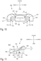
- the articulation component 100 is separately in the Fig. 9 to 11
- the support component is shown separately in the Fig. 7 and 8 shown.
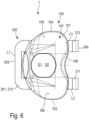
- the articulating component 100 has a proximal top surface 101, a distal bottom surface 102, a medial outer surface 103, a lateral outer surface 104, an anterior front surface 105, and a posterior back surface 106.
- the proximal top surface 101 and the distal bottom surface 102 are opposed to each other along a proximodistal axis.
- the medial outer surface 103 and the lateral outer surface 104 are opposed to each other along a mediolateral axis.
- the anterior front surface 105 and the posterior back surface 106 are opposed to each other along an anteroposterior axis. Said axes are orthogonal to each other.
- the upper side 101 of the articulation component 100 has an articulation surface 107 which is designed for articulation with a femoral component F.
- the femoral component F is in Fig. 2 shown schematically and cut away and can be formed by a natural distal femur or a femoral implant.
- the articulation surface 107 is formed by two articulation surface sections 108, 109, which are arranged opposite one another with respect to an imaginary sagittal mid-longitudinal plane of the articulation component 100 and can also be referred to as medial articulation surface section 108 and lateral articulation surface section 109.
- the articulation component 100 has a proximodistal continuous recess G1.
- the recess G1 divides the articulation surface 107 into the said surface sections 108, 109 and is to be regarded as optional.
- the recess G1 is therefore not present in all embodiments.
- the underside 102 of the articulation component 100 has a support surface 110 (see in particular Fig. 9 ).
- the support surface 110 has two support surface sections 111, 112 that are spaced apart mediolaterally from one another, which can also be referred to as medial support surface section 111 and lateral support surface section 112. Such a subdivision/division of the support surface 110 is not provided in all embodiments and is optional.
- the said recess G1 is arranged between the two support surface sections 111, 112 with respect to the mediolateral axis.
- the support component 200 has a proximal top surface 201, a distal bottom surface 202, a medial outer surface 203, a lateral outer surface 204, an anterior front surface 205, and a posterior back surface 206.
- the proximal top surface 201 and the distal bottom surface 202 are opposed to each other along the proximodistal axis.
- the medial outer surface 203 and the lateral outer surface 204 are opposed to each other along the mediolateral axis.
- the anterior front surface 205 and the posterior back surface 206 are opposed to each other along the anteroposterior axis.
- the support component 200 has a bearing surface 207 arranged on the distal underside 202.
- the bearing surface 207 is designed for storage on a tibial plateau TP.
- the TP is shown schematically in Fig. 2 shown and in the present case is formed by a resection surface of a proximal tibia T.
- the tibial plateau can be formed by a femoral implant component attached to the resection surface.
- the bearing surface 207 is in the present case parallel to an anteroposterior and mediolaterally extended transverse plane.
- the support component 200 has a recess G2 that runs along the proximodistal axis.
- the recess G2 divides the bearing surface 207 into two mediolaterally spaced-apart bearing surface sections 208, 209.
- the bearing surface sections 208, 209 can also be referred to as medial bearing surface section 208 and lateral bearing surface section 209.
- the recess G2 and the associated subdivision of the bearing surface 207 are optional and therefore not present in all embodiments.
- the support component 200 has a proximal ramp 210.
- the ramp 210 forms the upper side 201 and vice versa.
- the ramp 210 is longitudinally inclined along the anteroposterior axis and rises from the posterior rear side 206 towards the anterior front side of the support component 200.
- the ramp 210 and/or the upper side 201 is consequently inclined relative to the distal bearing surface 207.
- the longitudinal inclination of the ramp 210 runs in the present case at an angle ⁇ relative to the bearing surface 207 and thus also relative to the tibial plateau TP.
- the previously explained support surface 110 of the articulation component 100 (see Fig. 9 ) is longitudinally extended parallel to the ramp 210 and consequently inclined in accordance with the ramp 210.
- the support surface 110 in the embodiment shown is formed by the support surface sections 111, 112, which are consequently also longitudinally extended parallel to the ramp 210.
- the ramp 210 is divided into two ramp sections 211, 212 spaced apart mediolaterally due to the aforementioned recess G2.
- the ramp 210 has the two ramp sections 211, 212, which can also be referred to as the medial ramp section 211 and the lateral ramp section 212.
- Such a design of the ramp with multiple ramp sections is optional and therefore not present in all embodiments.
- the support component 200 has a guide device 213 with a guide track 214.
- the guide track 214 is in the Fig. 2 and 8 shown in dashed lines.
- the guide track 214 is longitudinally extended parallel to the ramp 210.
- the articulation component 100 and the support component 200 are linearly guided to one another by means of the guide device 213 and are linearly movable relative to one another.
- Linear mobility runs along the guide track 214.
- the articulation component 100 and the support component 200 are supported on one another via the support surface 110 and the ramp 210 in a way that is movable relative to one another.
- a relative movement between the articulation component 100 and the support component 200 allows a proximal distance between the articulation component 100 and the tibial plateau TP to be changed.
- the relative mobility allows a change in the proximodistal distance between the articulation surface 107 of the articulation component 100 and the bearing surface 207 of the support component 200.
- a proximodistal distance H1 is set.
- the articulation component 100 more precisely: its support surface 110, is supported in a first position relative to the support component 200 on the ramp 210 in relation to the guideway.
- the Fig. 4 to 6 The configuration of the tibial trial implant 1 shown is adopted with a different relative positioning of the two components 100, 200. In this case, a different proximodistal distance H4 is present (see in particular Fig. 5 ).
- the longitudinal inclination of the ramp 210 and thus also of the support surface 110 is approximately 15° in the present case. In embodiments not shown in the figures, the longitudinal inclination is between 10° and 45°.
- the change in the proximodistal distance occurs in the Fig. 1 to 11 shown embodiment, in which the surgeon holds the articulation component 100 stationary below the femoral component F and displaces the support component 200 along the anteroposterior axis relative to the articulation component 100 and the tibial plateau TP.
- the proximodistal distance can be increased by pushing the support component 200 forward in the posterior direction between the tibial plateau TP and the articulation component 100.
- the ramp-shaped design of the upper side 201 and the complementary design of the support surface 110 result in a wedge-shaped shape of the support component 200 in the mediolateral direction.
- the support component 200 can therefore also be referred to as a wedge.
- the support component 200 can, for example, start from the Fig. 5 shown configuration, in the anterior direction under the stationary articulation component 100.
- the articulation component 100 and the support component 200 are always guided and/or held against each other in a defined manner during such an adjustment of the proximodistal distance, in particular by means of the guide device 213.
- the guide device 213 has at least one guide slot 215.
- the guide slot 215 is longitudinally extended and defines the guide path 214.
- the guide device 213 has two guide slots 215, although only one is shown in the figures.
- the guide slot 215 shown is recessed into the medial outer side 203 of the support component 200.
- the guide slot not shown is recessed into the lateral outer side 204.
- the articulation component 100 has at least one guide element 113, 114 for interacting with the guide device 213 of the support component 200.
- a medial guide element 113 and a lateral guide element 114 are present and each designed as a guide pin 115.
- the medial guide element 113 engages in the medial guide slot 215 of the support component 200.
- the lateral guide element 114 engages in the lateral guide slot (not shown in the figures).
- the guide pins 115 interact with the guide slots in a sliding manner along the guide track 214.
- the guide slots 215 are open at one end.
- the guide slot 215 has an insertion opening 216 in the area of the posterior rear side 206.
- the medial guide pin 113 can be inserted into the guide slot 215 through the insertion opening 216.
- the support surface 110 is recessed proximally into the underside 102 of the articulation component 100.
- the support surface 110 is thus delimited by mediolaterally opposing wall sections 116, 117.
- the said wall sections 116, 117 can also be referred to as medial wall section 116 and lateral wall section 117.
- the medial wall section 116 lies in a form-fitting manner in the lateral direction on the medial outer side 203 of the articulation component.
- the lateral wall section 117 lies in a form-fitting manner in the medial direction on the lateral outer side 204 of the support component 200.
- the ramp 210 is provided with steps S1, S2, S3, S4 (see Fig. 2 ).
- This is provided with steps S1', S2 ⁇ , S3 ⁇ , S4 ⁇ (see Fig. 11 ). Due to the specific design of the present embodiment with two ramp sections 211, 212 and two support surface sections 111, 112, all respective sections have a stepped design.
- the steps S1 to S4 of the support component 200 are each assigned to a specific proximodistal distance.
- the step S1 defines the proximodistal distance H1 in the Fig. 1 to 3
- the step S4 defines the (larger) proximodistal distance H4 of the Fig. 4 to 6 shown configuration.
- the further steps S2, S3 define distances between the two proximodistal distances H1, H4.
- the steps S1 to S4 of the articulation component 200 rise from the posterior back 206 toward the anterior front 205 proximally.
- the steps S1' to S4' of the articulation component 100 rise from the posterior back 106 toward the anterior front 105 distally.
- stages S1 to S4 and the stages S1' to S4' are designed to complement each other.
- the steps S1 to S4 and S1' to S4' are each bevelled.
- the support component 200 can be displaced anteriorly to the articulation component 100 in a relatively slidable manner in the manner described above, without the steps S1 to S4 of the support component 200 and the steps S1' to S4' of the articulation component 200 getting caught on one another.
- the proximodistal height between the steps is 2 mm. In embodiments not shown in the figures, the height is between 1 mm and 3 mm. In the present case, there are also four steps.
- the support component 200 When the support component 200 is advanced below the articulation component 100, the latter is moved downwards due to the step-wise design of the ramp 210 and the support surface 110. raised proximally by 2 mm increments. When pulled out anteriorly, the height of the articulation component 100 in relation to the tibial plateau TP is reduced by 2 mm increments.
- the steps S1 to S4 and S1 ⁇ to S4 ⁇ are preferably provided with bulges and complementary indentations which releasably interlock and counteract unwanted relative movement between the articulation component and the support component.
- the said indentations and outdentations are not shown separately in the figures.
- the articulation component 100 and the support component 200 are each made of a biocompatible plastic material K. Different manufacturing processes are conceivable. In the present case, production is carried out by means of 3D printing.
- Fig. 1 to 11 In the embodiment shown, the articulation component 100 and the support component 200 are each additively manufactured separately from one another. After the additive manufacturing of the two components 100, 200, they are assembled to form the tibial trial implant 1.
- the support component 200 has a U-shaped configuration.
- the two ramp sections 211, 212 each form an elongated leg L2, L3 of the said U-shape.
- the U-shape also has a further (short) leg L1.
- the further leg L1 is arranged mediolaterally and elongated at the end of the two legs L2, L3 and connects them to one another.
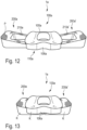
- a tibial trial implant 1a is shown in the Fig. 12 and 13 A further embodiment of a tibial trial implant 1a according to the invention.
- the tibial trial implant 1a is essentially identical in terms of its structure and function to the tibial trial implant 1 according to the Fig. 1 to 11 . To avoid repetition, only the essential differences are discussed below. Functionally equivalent components and/or sections are used for the tibial trial implant 1a according to the Fig. 12 and 13 not explained separately. Instead, to avoid repetition, reference is made to the tibial trial implant 1 according to the Fig. 1 to 11 What has been said is referred to and expressly referred to.
- the main difference of the tibial trial implant 1a is the presence of two support components 200a, 200a'.
- the two support components 200a, 200a ⁇ can also be referred to as the first support component 200a and the second support component 200a' and are designed identically to each other.
- the two support components 200a, 200a' are on both sides of a imaginary sagittal mid-longitudinal plane of the articulation component 100a and guided separately from each other in a linearly movable manner relative to the articulation component 100a.
- Fig. 12 a first configuration in which a minimum proximodistal distance is set.
- the Fig. 13 shows a comparatively larger height adjustment.
- the Fig. 12 and 13 The embodiment shown is additively manufactured from a biocompatible plastic material K.
- the tibial trial implant 1a is manufactured using a common 3D printing process. As a result of the common printing process, the components 100a, 200a, 200a' are permanently connected to one another via the guide devices and at the same time are movable relative to one another.
Landscapes
- Health & Medical Sciences (AREA)
- Orthopedic Medicine & Surgery (AREA)
- Transplantation (AREA)
- Engineering & Computer Science (AREA)
- Heart & Thoracic Surgery (AREA)
- Animal Behavior & Ethology (AREA)
- Cardiology (AREA)
- Biomedical Technology (AREA)
- Physical Education & Sports Medicine (AREA)
- Vascular Medicine (AREA)
- Life Sciences & Earth Sciences (AREA)
- Oral & Maxillofacial Surgery (AREA)
- General Health & Medical Sciences (AREA)
- Public Health (AREA)
- Veterinary Medicine (AREA)
- Chemical & Material Sciences (AREA)
- Manufacturing & Machinery (AREA)
- Materials Engineering (AREA)
- Prostheses (AREA)
Abstract
eine Artikulationskomponente (100, 100a) mit einer proximalen Artikulationsfläche (107), die zur Artikulation mit einer femoralen Komponente (F) eingerichtet ist, und mit einer distalen Unterseite (102),
wenigstens eine Stützkomponente (200, 200a, 200a`) mit einer distalen Lagerfläche (207), die zur Lagerung auf einem Tibiaplateau (TP) eingerichtet ist, einer proximalen Oberseite (201), die eine relativ zu der distalen Lagerfläche geneigte Rampe (210, 210a, 210a') bildet, und mit einer Führungseinrichtung (213), die eine parallel zu der Rampe längserstreckte Führungsbahn (214) aufweist,
wobei die Unterseite der Artikulationskomponente eine parallel zu der Rampe geneigte Stützfläche (110, 110a) aufweist,
und wobei die Artikulationskomponente an der Führungseinrichtung gehalten und entlang der Führungsbahn relativ zu der Stützkomponente linearbeweglich mit ihrer Stützfläche auf der Rampe abgestützt ist,
wodurch eine Relativbewegung zwischen der Artikulationskomponente und der Stützkomponente eine Veränderung eines proximodistalen Abstands (H1, H4) zwischen der Artikulationsfläche der Artikulationskomponente und der Lagerfläche der Stützkomponente bewirkt.
Description
- Die Erfindung betrifft ein tibiales Probeimplantat zur Verwendung bei einer Kniegelenkersatzoperation.
- Bei einer Kniegelenkersatzoperation (englisch: total knee athroplasty (TKA)) werden Gelenkflächen des Femurs und der Tibia durch künstliche Gelenkflächen einer Kniegelenkprothese ersetzt. Kniegelenkprothesen umfassen üblicherweise ein Femurimplantat, ein Tibiaimplantat und eine Meniskuskomponente, die oftmals auch als Gleitfläche bezeichnet wird. Das Femurimplantat wird am distalen Ende des Femurs implantiert. Das Tibiaimplantat wird am proximalen Ende der Tibia implantiert. Die Meniskuskomponente ist proximodistal zwischen Tibia- und Femurimplantat angeordnet. Um eine einwandfreie Funktion des künstlichen Gelenkersatzes zu gewährleisten, müssen die besagten Implantate hinsichtlich ihrer Lage und Orientierung in Bezug auf die Körperachsen des Patienten in definierter Weise präzise positioniert werden. Zusätzlich zu der präzisen Positionierung ist es wichtig, dass die Implantate jeweils mit für die Anatomie des Patienten passenden Abmessungen ausgewählt und implantiert werden. Hinsichtlich der Meniskuskomponente ist insbesondere deren proximodistale Höhe ein wesentliches Kriterium.
- Das tibiale Probeimplantat dient einer intraoperativen Ermittlung der erforderlichen proximodistalen Höhe der zu implantierenden Meniskuskomponente. Im Speziellen wird das tibiale Probeimplantat verwendet, um bei bereits implantiertem Femurimplantat eine optimale Bandspannung und Gelenklinie zu testen. Abhängig vom Ergebnis dieser Testung wird die Meniskuskomponente ausgewählt und implantiert. Die besagte Testung kann beispielsweise anhand unterschiedlicher Meniskusprobekomponenten mit unterschiedlichen definierten Höhen erfolgen.
- Aus der
EP 4 011 334 A1 ist ein tibiales Probeimplantat mit einer oberen Platte und einer unteren Platte bekannt. Die obere Platte weist eine proximale Artikulationsfläche zur Artikulation mit einer femoralen Komponente auf. Die untere Platte weist eine distale Lagerfläche zur Lagerung auf einem Tibiaplateau auf. Zwischen der oberen Platte und der unteren Platte ist ein Höheneinstellmechanismus angeordnet. Der Höheneinstellmechanismus dient einer Einstellung eines proximodistalen Abstands zwischen der Artikulationsfläche der oberen Platte und der Lagerfläche der unteren Platte und damit der proximodistalen Höhe des Probeimplantats. Der Höheneinstellmechanismus weist zwei miteinander gekoppelte Scherengelenkmechanismen auf. - Aus der
DE 10 2020 208 501 A1 ist ein weiteres tibiales Probeimplantat bekannt. Das bekannte tibiale Probeimplantat weist ein Oberteil mit einer proximal angeordneten Gleitfläche zum gleitenden Zusammenwirken mit einer femoralen Komponente auf. Das Unterteil ist zur tibialen Fixierung vorgesehen. Zwischen dem Oberteil und dem Unterteil ist ein Höheneinstellmechanismus angeordnet, mittels dessen das Oberteil relativ zu dem Unterteil in Hochrichtung geführt verlagerbar ist. Die Verlagerung des Oberteils dient wiederum der Einstellung des besagten proximodistalen Abstands und damit der Höhe des Probeimplantats. Der Höheneinstellmechanismus weist ein Kurvengetriebe mit einem rotierenden Antriebsrad auf. - Aus der
EP 4 082 485 A1 ist ein weiteres tibiales Probeimplantat bekannt. Dieses Probeimplantat weist eine Lagerkomponente mit einer proximalen Artikulationsfläche und einer distalen Fläche auf. Zudem ist eine Plattenkomponente mit einer proximalen Oberfläche und einer distalen Befestigungsoberfläche vorhanden. Zwischen der Lagerkomponente und der Plattenkomponente ist eine Abstandseinstellanordnung angeordnet, die einerseits lösbar mit der Lagerkomponente und andererseits lösbar mit der Plattenkomponente in Eingriff kommt und die beiden Komponenten in proximodistaler Richtung begrenzt beweglich miteinander koppelt. Weiter weist das bekannte tibiale Probeimplantat mehrere Abstandsstücke (englisch: shims) auf, die zur Einstellung der proximodistalen Höhe zwischen die Lager- und die Plattenkomponente in die Abstandseinstellanordnung einschiebbar sind. Unterschiedliche Abstandsstücke weisen unterschiedliche proximodistale Dicken auf. Je nach Auswahl des Abstandsstücks kann eine unterschiedliche proximodistale Höhe des Probeimplantats eingestellt werden. - Aufgabe der Erfindung ist es, ein tibiales Probeimplantat bereitzustellen, das einen gegenüber dem Stand der Technik vereinfachten Aufbau aufweist und eine einfache Anwendung erlaubt.
- Diese Aufgabe wird durch das Bereitstellen eines tibialen Probeimplantats mit den Merkmalen des Anspruchs 1 gelöst.
- Das erfindungsgemäße tibiale Probeimplantat weist eine Artikulationskomponente und wenigstens eine Stützkomponente auf. Die Artikulationskomponente weist eine proximale Artikulationsfläche und eine distale Unterseite auf. Die proximale Artikulationsfläche ist zur Artikulation mit einer femoralen Komponente eingerichtet. Die wenigstens eine Stützkomponente weist eine distale Lagerfläche, eine proximale Oberseite und eine Führungseinrichtung auf. Die distale Lagerfläche ist zur Lagerung auf einem Tibiaplateau eingerichtet. Die proximale Oberseite bildet eine relativ zu der distalen Lagerfläche geneigte Rampe. Die Führungseinrichtung weist eine parallel zu der Rampe längserstreckte Führungsbahn auf. Die Unterseite der Artikulationskomponente weist eine parallel zu der Rampe geneigte Stützfläche auf. Die Artikulationskomponente ist an der Führungseinrichtung gehalten und entlang der Führungsbahn relativ zu der Stützkomponente linearbeweglich mit ihrer Stützfläche auf der Rampe abgestützt. Eine Relativbewegung zwischen der Artikulationskomponente und der Stützkomponente bewirkt folglich eine Veränderung eines proximodistalen Abstands zwischen der Artikulationsfläche der Artikulationskomponente und der Lagerfläche der Stützkomponente. Durch die erfindungsgemäße Lösung weist das tibiale Probeimplantat einen besonders einfachen Aufbau auf. Insbesondere kann auf komplex aufgebaute Höheneinstellmechanismen und auf die Verwendung unterschiedlicher Meniskusprobekomponenten mit unterschiedlichen Höhen verzichtet werden. Stattdessen ist es vorgesehen, dass die wenigstens eine Stützkomponente nach Art eines Keils zwischen das Tibiaplateau und die Artikulationskomponente geschoben werden kann. Zu diesem Zweck ist die Oberseite der Stützkomponente relativ zu der distalen Lagerfläche geneigt und bildet die besagte Rampe. Die distale Unterseite der Artikulationskomponente ist zu der Rampe parallel längserstreckt und folglich dementsprechend geneigt. Um undefinierte Relativbewegungen zwischen der Artikulationskomponente und der Stützkomponente zu unterbinden, ist die Führungseinrichtung vorgesehen. Die Führungseinrichtung legt die Artikulationskomponente und die Stützkomponente entlang der parallel zu der Rampe - und damit auch der Stützfläche - erstreckten Führungsbahn linearbeweglich aneinander fest. Eine Relativbewegung zwischen der Artikulationskomponente und der Stützkomponente entlang der Führungsbahn bewirkt folglich eine Veränderung des proximodistalen Abstands. Je größer die Relativbewegung, desto größer die Veränderung des Abstands. Ausgehend von einer (intraoperativen) Situation, in welcher die Artikulationskomponente örtlich festgelegt ist, kann die Stützkomponente mehr oder weniger weit zwischen die Artikulationskomponente und das Tibiaplateau eingeschoben werden. In Abhängigkeit des Vorschubs der Stützkomponente wird die Artikulationskomponente mehr oder weniger weit proximal in Richtung der femoralen Komponente verlagert und damit der proximodistale Abstand zwischen der Lagerfläche der Stützkomponente - und damit dem Tibiaplateau - und der Artikulationsfläche verändert. Die femorale Komponente und das Tibiaplateau sind nicht Bestandteil des tibialen Probeimplantats. Bei der femoralen Komponente kann es sich um einen natürlichen distalen Femur oder eine femorale Implantatskomponente handeln. Das Tibiaplateau kann durch eine Resektionsfläche an der proximalen Tibia oder eine künstliche Plateaufläche, die an der Resektionsfläche befestigt ist, gebildet sein. Die zur Lagerung auf dem Tibiaplateau eingerichtete Lagerfläche ist vorzugsweise plan und parallel zu einer anteroposterior und mediolateral erstreckten Transversalebene. Die durch die Oberseite der Stützkomponente gebildete Rampe ist gegenüber der Transversalebene geneigt, so dass sich, insbesondere bei einer mediolateralen oder anteroposterioren Blickrichtung, eine keilförmige Gestalt der Stützkomponente ergibt. Bei einer Relativbewegung zwischen der Tibia- und der Stützkomponente gleiten die Stützfläche der Artikulationskomponente und die Rampe aneinander ab. Gleichzeitig erfolgt eine Führung der beiden Komponenten mittels der Führungseinrichtung. Die Führungseinrichtung ist wenigstens abschnittsweise an der Stützkomponente angeordnet und/oder ausgebildet und wirkt zwecks Führung mit einem hierfür eingerichteten Abschnitt der Artikulationskomponente zusammen. Bei einer Ausgestaltung weist das tibiale Probeimplantat exakt eine Stützkomponente auf, so dass ein insgesamt zweiteiliger Aufbau vorgesehen ist. Bei einer weiteren Ausgestaltung weist das tibiale Probeimplantat exakt zwei Stützkomponenten auf, so dass ein insgesamt dreiteiliger Aufbau des Probeimplantats vorgesehen ist.
- Die in dieser Beschreibung verwendeten Lage- und Richtungsbezeichnungen beziehen sich auf den Körper eines Patienten, insbesondere dessen Tibia, und sind gemäß ihrer üblichen anatomischen Bedeutung zu verstehen. Folglich bedeutet "anterior" vordere/r oder vorne liegend, "posterior" hintere/r oder hinten liegend, "medial" innere/r oder innen liegend, "lateral" äußere/r oder außen liegend, "proximal" zum Körperzentrum hin oder oben liegend, "distal" vom Körperzentrum entfernt oder unten liegend. Weiter bedeuten "proximodistal" entlang, vorzugsweise parallel zu, einer proximal-distal ausgerichteten Achse, "anteroposterior" entlang, vorzugsweise parallel zu, einer anterior-posterior ausgerichteten Achse und "mediolateral" entlang, vorzugsweise parallel zu, einer medial-lateral ausgerichteten Achse. Die besagten Achsen sind orthogonal zueinander ausgerichtet und können selbstverständlich in Bezug zu nicht mit der Anatomie des Patienten in Verbindung stehenden X-, Y- und Z-Achsen gesetzt werden. Beispielsweise kann die proximodistale Achse alternativ als Z-Achse bezeichnet werden. Die medio-laterale Achse kann als Y-Achse bezeichnet werden. Die anterior-posteriore Achse kann als X-Achse bezeichnet werden. Zur besseren Veranschaulichung und der Einfachheit der Bezeichnungen wegen werden nachfolgend in erster Linie die besagten anatomischen Lage- und Richtungsbezeichnungen verwendet. Weiter werden Bezeichnungen wie "Oberseite" in Bezug auf eine distal gerichtete Blickrichtung verwendet. Dementgegen werden Bezeichnungen wie "Unterseite" in Bezug auf eine proximal gerichtete Blickrichtung verwendet.
- In Ausgestaltung der Erfindung ist die Rampe und/oder die Stützfläche plan und weist eine Oberflächenprofilierung auf, die dazu eingerichtet ist, einem Abrutschen der Artikulationskomponente von der Rampe entgegenzuwirken. Hierdurch wird einer ungewollten Veränderung eines einmal eingestellten proximodistalen Abstands entgegengewirkt. Die Oberflächenprofilierung bewirkt eine erhöhte Reibung zwischen der Rampe und der Stützfläche. Die Oberflächenprofilierung weist vorzugsweise in Normalenrichtung der Rampe und/oder Stützfläche aufragende Erhebungen und/oder eingebrachte Vertiefungen auf. Durch die plane Gestaltung der Rampe und/oder der Stützfläche ist vorzugsweise eine stufenlose Veränderung des proximodistalen Abstands möglich.
- In weiterer Ausgestaltung der Erfindung sind die Rampe und die Stützfläche jeweils mit einer Abfolge von Stufen versehen, wodurch die Relativbewegung zwischen der Artikulationskomponente und der Stützkomponente eine stufenweise Veränderung des proximodistalen Abstands bewirkt. Die Stufen weisen jeweils eine in proximodistaler Richtung erstreckte Höhe auf. Die Stufen steigen ausgehend von einem (niedrigen) Ende der Rampe in Richtung eines gegenüberliegenden (hohen) Endes an. Entsprechendes gilt, mutatis mutandis, für die Stufen der Stützfläche. Vorzugsweise sind die Stufen jeweils angeschrägt, so dass die Stützfläche und die Rampe - trotz vorhandener Stufen - entlang der Führungsbahn aneinander abgleiten können.
- In weiterer Ausgestaltung der Erfindung weisen die Stufen jeweils eine proximodistale Höhe zwischen 1 mm und 3 mm, bevorzugt 2 mm, auf, wobei jeweils wenigstens vier Stufen vorhanden sind. Hierdurch ergibt sich ein wenigstens 4-stufiger Einstellbereich für den proximodistalen Abstand. Dabei hat sich eine Höhe von 2 mm für die Stufen als besonders vorteilhaft erwiesen. Die genannte Höhe ist einerseits ausreichend klein, um auch geringe Veränderungen des Abstands einstellen zu können. Andererseits erlaubt eine Höhe von 2 mm pro Stufe bei wenigstens vier Stufen einen insgesamt ausreichend großen Einstellbereich. Die Höhe der einzelnen Stufen und die realisierbare Gesamthöhe des tibiales Probeimplantats orientiert sich vorzugsweise an den verfügbaren, unterschiedlich hohen Meniskuskomponenten, die in der Regel in den Höhen 10 mm, 12 mm, 14 mm, 16 mm, 18 mm, 20 mm, 22 mm und 24 mm verfügbar sind.
- In weiterer Ausgestaltung der Erfindung weisen die Stufen der Rampe jeweils eine konvexe Auswölbung auf und die Stufen der Stützfläche weisen jeweils eine komplementäre konkave Einwölbung auf, wobei die Auswölbungen und die Einwölbungen lösbar ineinandergreifen, wodurch einer ungewollten Relativbewegung zwischen der Artikulationskomponente und der Stützkomponente entgegengewirkt ist. Durch das Ineinandergreifen der Aus- und Einwölbungen wird ungewollten Relativbewegungen zwischen den komplementären Stufen und damit zwischen der Artikulationskomponente und der Stützkomponente entgegengewirkt. Hierdurch werden ungewollte Höhenveränderungen des tibialen Probeimplantats vermieden. Zur gewollten Relativbewegung kann der Eingriff zwischen den Einwölbungen und den Auswölbungen manuell überwunden werden, beispielweise indem die Artikulationskomponente geringfügig von der Stützkomponente angehoben wird. Es versteht sich, dass auch eine umgekehrte Anordnung von Auswölbungen und Einwölbungen vorgesehen sein kann. Folglich sind bei einer Ausgestaltung die konkaven Einwölbungen an den Stufen der Rampe und die konvexen Auswölbungen an den Stufen der Stützfläche vorhanden.
- In weiterer Ausgestaltung der Erfindung weist die Rampe und/oder die Stützfläche eine Längsneigung von 10° bis 45°, bevorzugt von 15° bis 30°, besonders bevorzugt von 20°, auf. Die Längsneigung bemisst sich relativ zu der Lagerfläche und damit auch dem Tibiaplateau. Alternativ oder zusätzlich bemisst die Längsneigung sich relativ zu einer gedachten Transversalebene. Je steiler die Längsneigung ist, desto größer ist ein Übersetzungsverhältnis zwischen der Relativbewegung der Tibia- und der Stützkomponente und der Veränderung des proximodistalen Abstands. Eine kleine Relativbewegung bewirkt folglich eine in Relation große Veränderung des proximodistalen Abstands. Gleichzeitig ist hierbei ein relativ großer Kraftaufwand zum Vorschub der Stützkomponente erforderlich. Umgekehrtes gilt, mutatis mutandis, für flache Längsneigungen. Vor diesem Hintergrund hat sich eine Längsneigung in dem Bereich von 15 bis 30° als vorteilhaft erwiesen, wobei 20° als Optimum angesehen werden kann.
- In weiterer Ausgestaltung der Erfindung sind die Rampe und die Stützfläche anteroposterior längsgeneigt. Mit anderen Worten erhebt die Rampe sich entlang einer anteroposterioren Achse, wobei Entsprechendes sinngemäß für die Stützfläche gilt. Da die Führungsbahn parallel zu der Rampe und damit auch der Stützfläche längserstreckt ist, gilt das Gesagte auch für deren Längsneigung. Bei dieser Ausgestaltung wird die wenigstens eine Stützkomponente zur Veränderung des proximodistalen Abstands relativ zu der Artikulationskomponente anteroposterior verlagert. Vorzugsweise bewirkt ein von anterior nach posterior gerichteter relativer Vorschub der Stützkomponente eine Vergrößerung des proximodistalen Abstands. Eine Verringerung erfolgt in kinematisch umgekehrter Weise.
- In weiterer Ausgestaltung der Erfindung sind die Rampe und die Stützfläche mediolateral längsgeneigt. Die Rampe steigt folglich entlang einer mediolateralen Achse an. Dies gilt, mutatis mutandis, auch für die Stützfläche. Bei dieser Ausgestaltung kann die wenigstens eine Stützkomponente zur intraoperativen Veränderung des proximodistalen Abstands relativ zu der Artikulationskomponente in mediolateraler Richtung verlagert werden. Mit anderen Worten ist ein "seitlicher" relativer Vorschub der Stützkomponente vorgesehen. Sofern das tibiale Probeimplantat exakt eine Stützkomponente aufweist, kann diese bei dieser Ausgestaltung der Erfindung lateral oder medial einer sagittalen Mittellängsebene der Artikulationskomponente angeordnet sein. Ist die Stützkomponente lateral angeordnet, bewirkt ein medialer Vorschub vorzugsweise eine Vergrößerung des proximodistalen Abstands. Ist die Stützkomponente stattdessen medial angeordnet, bewirkt vorzugsweise ein lateraler Vorschub eine Vergrößerung des proximodistalen Abstands. Für eine Verringerung des proximodistalen Abstands wird die Stützkomponente kinematisch entgegengesetzt verlagert.
- In weiterer Ausgestaltung der Erfindung sind zwei Stützkomponenten vorhanden und beidseits einer sagittalen Mittellängsebene der Artikulationskomponente angeordnet, wobei die beiden Stützkomponenten zur Veränderung des proximodistalen Abstands mediolateral entgegengesetzt relativ zu der Artikulationskomponente beweglich sind. Bei dieser Ausgestaltung kann auch von einer ersten Stützkomponente und einer zweiten Stützkomponente gesprochen werden. Die erste Stützkomponente ist vorzugsweise auf einer lateralen Seite der sagittalen Mittellängsebene angeordnet. Die zweite Stützkomponente ist vorzugsweise auf einer medialen Seite der sagittalen Mittellängsebene angeordnet. Zur Veränderung des proximodistalen Abstands werden die beiden Stützkomponenten zueinander entgegengesetzt relativ zu der Artikulationskomponente bewegt. Diese Ausgestaltung erlaubt insbesondere eine medial und lateral quantitativ unterschiedliche Veränderung des proximodistalen Abstands. Beispielsweise kann die Artikulationsfläche auf einer medialen Seite weiter proximal angehoben werden als auf einer lateralen Seite oder umgekehrt. Hierdurch kann der Anatomie des Patienten in verbesserter Weise Rechnung getragen werden.
- In weiterer Ausgestaltung der Erfindung weist die Führungseinrichtung wenigstens eine Führungskulisse auf, in welche wenigstens ein Führungsstift der Artikulationskomponente entlang der Führungsbahn gleitbeweglich eingreift. Die Führungskulisse ist in die Stützkomponente eingebracht und definiert die Führungsbahn. Sofern die Rampe und die Stützfläche jeweils mit einer Abfolge von Stufen versehen sind, gilt dies vorzugsweise auch für die Führungskulisse. In diesem Fall sind die Stufen der Führungskulisse parallel versetzt zu den Stufen der Rampe. Der wenigstens eine Führungsstift ist an der Artikulationskomponente angeordnet und/oder ausgebildet. Der Führungsstift greift entlang der Führungsbahn beweglich in die Führungskulisse ein. Bei einer Ausgestaltung ist die Führungskulisse einends offen und weist an ihrem offenen Ende eine Einführöffnung für die Führungsstift auf. Zwecks Montage des tibialen Probeimplantats kann der Führungsstift durch die Einführöffnung in die Führungskulisse eingeführt werden. Bei einer weiteren Ausgestaltung ist die Führungskulisse an ihren gegenüberliegenden Enden geschlossen. Zwecks Montage kann der Führungsstift bei dieser Ausgestaltung relativ zu der Artikulationskomponente verlagerbar sein. Alternativ kann eine additive Fertigung gemäß einer nachfolgend noch näher beschriebenen Ausgestaltung vorgesehen sein. Bei einer Ausgestaltung sind zwei zueinander parallel erstreckte Führungskulissen und dementsprechend zwei Führungsstifte vorgesehen.
- In weiterer Ausgestaltung der Erfindung weist die Führungskulisse einends der Führungsbahn eine Einführöffnung aufweist, die ausgehend von der Lagerfläche im Wesentlichen senkrecht zu der Führungsbahn in die Führungskulisse mündet und durch welche der wenigstens eine Führungsstift in die Führungskulisse einführbar ist. Zum Einführen des Führungsstifts kann die Artikulationskomponente mit einer gegeneinander vertauschten Ausrichtung ihrer Artikulationsfläche und ihrer Unterseite, d.h. mit etwa proximal ausgerichteter Unterseite, an der Stützkomponente angesetzt werden. Nach Einführen des wenigstens einen Führungsstifts in die Führungskulisse kann die Artikulationskomponente um 180° gedreht werden, so dass die Artikulationsfläche und die Unterseite ihre vorgesehene Ausrichtung wieder einnehmen. Durch diese spezielle Montage oder auch "Einführbewegung" ist die Beweglichkeit zwischen der Artikulationskomponente und der Stützkomponente nur entlang der Führungsbahn möglich. Hierdurch wird ein ungewolltes Trennen der Komponenten, insbesondere in anteroposteriorer und/oder in proximodistaler Richtung, verhindert.
- In weiterer Ausgestaltung der Erfindung ist die Stützfläche proximal in die Unterseite der Artikulationskomponente eingesenkt und durch gegenüberliegende Wandabschnitte begrenzt, die jeweils senkrecht zu der Führungsbahn und senkrecht zu einer proximodistalen Achse formschlüssig an der Stützkomponente anliegen. Durch den besagten Formschluss wird eine nochmals verbesserte Führung der Relativbewegung zwischen der Tibia- und der Stützkomponente erreicht. Die Wandabschnitte liegen jeweils seitlich an der Stützkomponente, vorzugsweise der Rampe, an.
- In weiterer Ausgestaltung der Erfindung weist die Artikulationskomponente eine proximodistal von der Artikulationsfläche bis zu der Stützfläche erstreckte Aussparung auf, welche die Artikulationsfläche und die Stützfläche in jeweils einen medialen Flächenabschnitt und einen lateralen Flächenabschnitt teilt. Bei dieser Ausgestaltung weist die Artikulationsfläche folglich einen medialen Artikulationsflächenabschnitt und einen lateralen Artikulationsflächenabschnitt auf. Diese beiden Abschnitte sind beidseits der Aussparung einander gegenüberliegend angeordnet und um eine mediolaterale Abmessung der Aussparung voneinander beabstandet. Entsprechendes gilt, mutatis mutandis, für die Stützfläche, so dass ein medialer Stützflächenabschnitt und ein lateraler Stützflächenabschnitt vorhanden sind. Die Aussparung erlaubt insbesondere eine verbesserte Einsehbarkeit der distal/unterhalb der Artikulationskomponente angeordneten Stützkomponente. Sofern die Stützkomponente ebenfalls mit einer Aussparung versehen ist, kann das Tibiaplateau eingesehen werden. Dies erlaubt dem ausführenden Operateur eine verbesserte intraoperative Kontrolle.
- In weiterer Ausgestaltung der Erfindung weist die wenigstens eine Stützkomponente eine proximodistal durch die Rampe erstreckte Aussparung auf, welche die Rampe in zwei Rampenabschnitte teilt, die seitlich, insbesondere mediolateral oder anteroposterior, voneinander beabstandet sind. Die durch die Aussparung erstreckte Rampe ermöglicht zum einen eine Einsparung von Material und damit einhergehend von Fertigungsaufwand und Gewicht. Sofern die Artikulationskomponente gemäß der vorhergehenden Beschreibung mit einer Aussparung versehen ist, ermöglicht die Aussparung der Stützkomponente eine verbesserte Einsehbarkeit des distal/unter der Stützkomponente angeordneten Tibiaplateaus. Sofern die Rampe eine anteroposteriore Längsneigung aufweist, sind die beiden Rampenabschnitte mediolateral um die Abmessungen der Aussparung voneinander beabstandet. Folglich kann auch von einem medialen und einem lateralen Rampenabschnitt gesprochen werden. Sofern die Rampe eine mediolaterale Längsneigung aufweist, sind die beiden Rampenabschnitte um die Abmessungen der Aussparung anteroposterior voneinander beabstandet. In diesem Fall kann auch von einem anterioren Rampenabschnitt und einem posterioren Rampenabschnitt gesprochen werden. Beide Rampenabschnitte sind jeweils längserstreckt. Die Aussparung ist vorzugsweise in Längsrichtung der Rampe einends offen, wobei die Öffnung bevorzugt an einem niedrigen Ende der Rampe angeordnet ist.
- In weiterer Ausgestaltung der Erfindung weist die wenigstens eine Stützkomponente, in proximaler und/oder distaler Blickrichtung, eine U-förmige Gestalt auf, wobei die beiden Rampenabschnitte jeweils einen längserstreckten Schenkel der U-Form bilden. Die U-Form der Stützkomponente ermöglicht insbesondere eine ergonomische Handhabung. In der Anwendung des tibialen Probeimplantats kann die U-förmige Stützkomponente im Bereich eines die beiden längserstreckten Schenkel verbindenden Querschenkels zwischen den Fingern einer Hand gegriffen werden. Dies ist ergonomisch vorteilhaft.
- In weiterer Ausgestaltung der Erfindung sind die Artikulationskomponente und die wenigstens eine Stützkomponente jeweils aus einem biokompatiblen Kunststoffmaterial gefertigt. Biokompatible Kunststoffmaterialien sind der zuständigen Fachperson als solche bekannt. Die Verwendung solcher Kunststoffmaterialien für die Artikulationskomponente und die Stützkomponente bietet besondere Vorteile. Vorzugsweise sind die Artikulationskomponente und die wenigstens eine Stützkomponente jeweils einstückig aus dem besagten Kunststoffmaterial gefertigt. Die Fertigung kann beispielsweise mittels Spritzgießens erfolgen. Bei einer weiteren Ausgestaltung erfolgt stattdessen eine additive Fertigung.
- In weiterer Ausgestaltung der Erfindung sind die Artikulationskomponente und die wenigstens eine Stützkomponente additiv mittels eines gemeinsamen 3D-Druckvorgangs gefertigt, wodurch die Artikulationskomponente und die wenigstens eine Stützkomponente über die Führungseinrichtung unlösbar miteinander verbunden und zueinander relativbeweglich sind. Bei dieser Ausgestaltung der Erfindung sind die Artikulationskomponente und die wenigstens eine Stützkomponente unverlierbar aneinander festgelegt. Durch den gemeinsamen 3D-Druckvorgang ist kein gesonderter Montageschritt zur Verbindung der Artikulationskomponente mit der wenigstens einen Stützkomponente erforderlich. Bevorzugt erfolgt der 3D-Druck unter Verwendung eines biokompatiblen Kunststoffmaterials.
- Weitere Vorteile und Merkmale der Erfindung ergeben sich aus den Ansprüchen sowie aus der nachfolgenden Beschreibung bevorzugter Ausführungsbeispiele der Erfindung, die anhand der Zeichnungen dargestellt sind.
- Fig. 1
- zeigt in schematischer Perspektivdarstellung eine Ausführungsform eines tibialen Probeimplantats mit einer Artikulationskomponente und einer Stützkomponente, wobei die Artikulationskomponente und die Stützkomponente relativ zueinander eine erste Konfiguration einnehmen,
- Fig. 2
- das tibiale Probeimplantat nach
Fig. 1 in einer schematischen Seitenansicht mit lateraler Blickrichtung, - Fig. 3
- das tibiale Probeimplantat nach den
Fig. 1 und 2 in einer schematischen Draufsicht mit distaler Blickrichtung, - Fig. 4
- eine weitere schematische Perspektivdarstellung des tibialen Probeimplantats nach den
Fig. 1 bis 3 , wobei die Artikulationskomponente und die Stützkomponente relativ zueinander eine zweite Konfiguration einnehmen, - Fig. 5, 6
- das tibiale Probeimplantat in der Konfiguration gemäß
Fig. 4 in einer schematischen Seitenansicht (Fig. 5 ) und einer schematischen Draufsicht (Fig. 6 ), - Fig. 7
- die Stützkomponente des tibialen Probeimplantats nach den
Fig. 1 bis 6 in einer schematischen Perspektivansicht, - Fig. 8
- die Stützkomponente nach
Fig. 7 in einer schematischen Seitenansicht, - Fig. 9
- in schematischer Perspektivdarstellung die Artikulationskomponente des tibialen Probeimplantats nach den
Fig. 1 bis 6 , - Fig. 10
- die Artikulationskomponente nach
Fig. 9 in einer schematischen Vorderansicht mit posterior gerichteter Blickrichtung, - Fig. 11
- die Artikulationskomponente nach den
Fig. 9 und10 in einer schematischen Schnittdarstellung entlang eines Schnitts A-A gemäßFig. 10 , und - Fig. 12, 13
- schematische Perspektivdarstellungen einer weiteren Ausführungsform eines erfindungsgemäßen tibialen Probeimplantats in einer ersten Konfiguration (
Fig. 12 ) und einer zweiten Konfiguration (Fig. 13 ). - Gemäß den
Fig. 1 bis 6 ist ein tibiales Probeimplantat 1 zur Verwendung bei einer Kniegelenkersatzoperation vorgesehen. Das tibiale Probeimplantat 1 dient der Ermittlung einer proximodistalen Höhe eines Tibiaimplantats und wird in der medizinischen Fachsprache oftmals auch als Probegleitfläche bezeichnet. - Das tibiale Probeimplantat 1 weist eine Artikulationskomponente 100 und eine Stützkomponente 200 auf. Die Artikulationskomponente 100 ist gesondert in den
Fig. 9 bis 11 gezeigt. Die Stützkomponente ist gesondert in denFig. 7 und 8 gezeigt. - Die Artikulationskomponente 100 weist eine proximale Oberseite 101, eine distale Unterseite 102, eine mediale Außenseite 103, eine laterale Außenseite 104, eine anteriore Vorderseite 105 und eine posteriore Rückseite 106 auf. Die proximale Oberseite 101 und die distale Unterseite 102 liegen entlang einer proximodistalen Achse einander gegenüber. Die mediale Außenseite 103 und die laterale Außenseite 104 liegen entlang einer mediolateralen Achse einander gegenüber. Die anteriore Vorderseite 105 und die posteriore Rückseite 106 liegen entlang einer anteroposterioren Achse einander gegenüber. Die besagten Achsen sind zueinander orthogonal.
- Die Oberseite 101 der Artikulationskomponente 100 weist eine Artikulationsfläche 107 auf, die zur Artikulation mit einer femoralen Komponente F eingerichtet ist. Die femorale Komponente F ist in
Fig. 2 schematisch und abgeschnitten gezeigt und kann durch einen natürlichen distalen Femur oder ein Femurimplantat gebildet sein. - Bei der gezeigten Ausführungsform ist die Artikulationsfläche 107 durch zwei Artikulationsflächenabschnitte 108, 109 gebildet, die in Bezug auf eine gedachte sagittale Mittellängsebene der Artikulationskomponente 100 einander gegenüberliegend angeordnet sind und auch als medialer Artikulationsflächenabschnitt 108 und lateraler Artikulationsflächenabschnitt 109 bezeichnet werden können.
- Zwischen den Artikulationsflächenabschnitten 108, 109 weist die Artikulationskomponente 100 vorliegend eine proximodistal durchgängige Aussparung G1 auf. Die Aussparung G1 untergliedert die Artikulationsfläche 107 in die besagten Flächenabschnitte 108, 109 und ist als optional anzusehen. Die Aussparung G1 ist folglich nicht bei sämtlichen Ausführungsformen vorhanden.
- Die Unterseite 102 der Artikulationskomponente 100 weist eine Stützfläche 110 auf (siehe insbesondere
Fig. 9 ). Bei der gezeigten Ausführungsform weist die Stützfläche 110 zwei mediolateral voneinander beabstandete Stützflächenabschnitte 111, 112 auf, die auch als medialer Stützflächenabschnitt 111 und lateraler Stützflächenabschnitt 112 bezeichnet werden können. Eine solche Untergliederung/Teilung der Stützfläche 110 ist nicht bei sämtlichen Ausführungsformen vorgesehen und optional. Die besagte Aussparung G1 ist in Bezug auf die mediolaterale Achse zwischen den beiden Stützflächenabschnitten 111, 112 angeordnet. - Die Stützkomponente 200 weist eine proximale Oberseite 201, eine distale Unterseite 202, eine mediale Außenseite 203, eine laterale Außenseite 204, eine anteriore Vorderseite 205 und eine posteriore Rückseite 206 auf. Die proximale Oberseite 201 und die distale Unterseite 202 liegen entlang der proximodistalen Achse einander gegenüber. Die mediale Außenseite 203 und die laterale Außenseite 204 liegen entlang der mediolateralen Achse einander gegenüber. Die anteriore Vorderseite 205 und die posteriore Rückseite 206 liegen entlang der anteroposterioren Achse einander gegenüber.
- Weiter weist die Stützkomponente 200 eine an der distalen Unterseite 202 angeordnete Lagerfläche 207 auf. Die Lagerfläche 207 ist zur Lagerung auf einem Tibiaplateau TP eingerichtet. Das TP ist schematisch in
Fig. 2 gezeigt und vorliegend durch eine Resektionsfläche einer proximalen Tibia T gebildet. Alternativ kann das Tibiaplateau durch eine an der Resektionsfläche befestigte femorale Implantatskomponente gebildet sein. Die Lagerfläche 207 ist vorliegend parallel zu einer anteroposterior und mediolateral ausgedehnten Transversalebene. - Bei der gezeigten Ausführungsform weist die Stützkomponente 200 eine entlang der proximodistalen Achse durchgängige Aussparung G2 auf. Die Aussparung G2 unterteilt die Lagerfläche 207 in zwei mediolateral voneinander beabstandete Lagerflächenabschnitte 208, 209. Die Lagerflächenabschnitte 208, 209 können auch als medialer Lagerflächenabschnitt 208 und lateraler Lagerflächenabschnitt 209 bezeichnet werden. Die Aussparung G2 und die damit einhergehende Unterteilung der Lagerfläche 207 sind optional und folglich nicht bei sämtlichen Ausführungsformen vorhanden.
- Weiter weist die Stützkomponente 200 eine proximale Rampe 210 auf. Die Rampe 210 bildet die Oberseite 201 und umgekehrt.
- Bei der gezeigten Ausführungsform ist die Rampe 210 entlang der anteroposterioren Achse längsgeneigt und steigt ausgehend von der posterioren Rückseite 206 in Richtung der anterioren Vorderseite der Stützkomponente 200 an. Die Rampe 210 und/oder die Oberseite 201 ist folglich relativ zu der distalen Lagerfläche 207 geneigt. Die Längsneigung der Rampe 210 verläuft vorliegend in einem Winkel α gegenüber der Lagerfläche 207 und damit auch gegenüber dem Tibiaplateau TP.
- Die bereits erläuterte Stützfläche 110 der Artikulationskomponente 100 (siehe
Fig. 9 ) ist parallel zu der Rampe 210 längserstreckt und folglich entsprechend der Rampe 210 geneigt. Wie bereits erläutert, ist die Stützfläche 110 bei der gezeigten Ausführungsform durch die Stützflächenabschnitte 111, 112 gebildet, die folglich ebenfalls parallel zu der Rampe 210 parallel längserstreckt sind. - Bei der gezeigten Ausführungsform ist die Rampe 210 aufgrund der bereits erwähnten Aussparung G2 in zwei mediolateral voneinander beabstandete Rampenabschnitte 211, 212 untergliedert. Mit anderen Worten weist die Rampe 210 die beiden Rampenabschnitte 211, 212 auf, die auch als medialer Rampenabschnitt 211 und lateraler Rampenabschnitt 212 bezeichnet werden können. Eine solche Gestaltung der Rampe mit mehreren Rampenabschnitten ist optional und folglich nicht bei allen Ausführungsformen vorhanden.
- Weiter weist die Stützkomponente 200 eine Führungseinrichtung 213 mit einer Führungsbahn 214 auf. Die Führungsbahn 214 ist in den
Fig. 2 und8 strichliert eingezeichnet. Die Führungsbahn 214 ist parallel zu der Rampe 210 längserstreckt. - Die Artikulationskomponente 100 und die Stützkomponente 200 sind mittels der Führungseinrichtung 213 aneinander lineargeführt und relativ zueinander linearbeweglich. Die Linearbeweglichkeit verläuft entlang der Führungsbahn 214. Dabei sind die Artikulationskomponente 100 und die Stützkomponente 200 über die Stützfläche 110 und die Rampe 210 relativ zueinander beweglich aneinander abgestützt. Durch eine Relativbewegung zwischen der Artikulationskomponente 100 und der Stützkomponente 200 ist ein proximaler Abstand zwischen der Artikulationskomponente 100 und dem Tibiaplateau TP veränderlich. Die Relativbeweglichkeit erlaubt eine Veränderung des proximodistalen Abstands zwischen der Artikulationsfläche 107 der Artikulationskomponente 100 und der Lagerfläche 207 der Stützkomponente 200. Bei der in den
Fig. 1 bis 3 gezeigten Konfiguration des tibialen Probeimplantats 1 ist ein proximodistaler Abstand H1 eingestellt. Die Artikulationskomponente 100, genauer: deren Stützfläche 110, ist hierfür vorliegend in einer in Bezug auf die Führungsbahn ersten Position relativ zu der Stützkomponente 200 auf der Rampe 210 abgestützt. Die in denFig. 4 bis 6 gezeigte Konfiguration des tibialen Probeimplantats 1 wird bei einer hiervon unterschiedlichen relativen Positionierung der beiden Komponenten 100, 200 eingenommen. Dabei liegt ein unterschiedlicher proximodistaler Abstand H4 vor (siehe insbesondereFig. 5 ). - Die Längsneigung der Rampe 210 und damit auch der Stützfläche 110 beträgt vorliegend in etwa 15°. Bei in den Figuren nicht gezeigten Ausführungsformen beträgt die Längsneigung zwischen 10° und 45°.
- Intraoperativ erfolgt die Veränderung des proximodistalen Abstands bei der in den
Fig. 1 bis 11 gezeigten Ausführungsform, indem der Operateur die Artikulationskomponente 100 ortsfest unterhalb der femoralen Komponente F hält und die Stützkomponente 200 entlang der anteroposterioren Achse relativ zu der Artikulationskomponente 100 und dem Tibiaplateau TP verlagert. Ausgehend von der inFig. 2 gezeigten Konfiguration kann der proximodistale Abstand erhöht werden, indem die Stützkomponente 200 in posteriorer Richtung zwischen das Tibiaplateau TP und die Artikulationskomponente 100 vorgeschoben wird. Durch die rampenförmige Gestaltung der Oberseite 201 und die hierzu komplementäre Gestaltung der Stützfläche 110 ergibt sich in mediolateraler Blickrichtung eine keilförmige Gestalt der Stützkomponente 200. Die Stützkomponente 200 kann folglich auch als Keil bezeichnet werden. Zum Verringern des proximodistalen Abstands kann die Stützkomponente 200, beispielsweise ausgehend von der inFig. 5 gezeigten Konfiguration, in anteriorer Richtung unter der ortsfest gehaltenen Artikulationskomponente 100 herausgezogen werden. Die Artikulationskomponente 100 und die Stützkomponente 200 sind bei einer solchen Verstellung des proximodistalen Abstands stets definiert aneinander geführt und/oder gehalten, insbesondere mittels der Führungseinrichtung 213. - Die Führungseinrichtung 213 weist bei der gezeigten Ausführungsform wenigstens eine Führungskulisse 215 auf. Die Führungskulisse 215 ist längserstreckt und definiert die Führungsbahn 214.
- Bei der gezeigten Ausführungsform weist die Führungseinrichtung 213 zwei Führungskulissen 215 auf, wobei in den Figuren lediglich eine gezeigt ist. Die gezeigte Führungskulisse 215 ist in die mediale Außenseite 203 der Stützkomponente 200 eingesenkt. Die nicht gezeigte Führungskulisse ist in die laterale Außenseite 204 eingesenkt.
- Bei der gezeigten Ausführungsform weist die Artikulationskomponente 100 wenigstens ein Führungselement 113, 114 zum Zusammenwirken mit der Führungseinrichtung 213 der Stützkomponente 200 auf. Vorliegend sind ein mediales Führungselement 113 und ein laterales Führungselement 114 vorhanden und jeweils als Führungsstift 115 gestaltet. Dabei greift das mediale Führungselement 113 in die mediale Führungskulisse 215 der Stützkomponente 200 ein. Das laterale Führungselement 114 greift in die (in den Figuren nicht gezeigte) laterale Führungskulisse ein. Die Führungsstifte 115 wirken entlang der Führungsbahn 214 gleitbeweglich mit den Führungskulissen zusammen.
- Bei der in den
Fig. 1 bis 11 gezeigten Ausführungsform sind die Führungskulissen 215 einends offen. Zur weiteren Erläuterung wird nachfolgend lediglich auf die mediale Führungskulisse 215 Bezug genommen. Hinsichtlich der nicht gezeigten lateralen Führungskulisse gilt, mutatis mutandis, Entsprechendes. - Die Führungskulisse 215 weist im Bereich der posterioren Rückseite 206 eine Einführöffnung 216 auf. Zwecks Montage des tibialen Probeimplantats 1 kann der mediale Führungsstift 113 durch die Einführöffnung 216 in die Führungskulisse 215 eingeführt werden.
- Wie insbesondere in den
Fig. 9 bis 11 gezeigt ist, ist die Stützfläche 110, genauer: die Stützflächenabschnitte 111, 112, proximal in die Unterseite 102 der Artikulationskomponente 100 eingesenkt. Die Stützfläche 110 ist folglich durch mediolateral gegenüberliegende Wandabschnitte 116, 117 begrenzt. Die besagten Wandabschnitte 116, 117 können auch als medialer Wandabschnitt 116 und lateraler Wandabschnitt 117 bezeichnet werden. Der mediale Wandabschnitt 116 liegt in lateraler Richtung formschlüssig an der medialen Außenseite 203 der Artikulationskomponente an. Der laterale Wandabschnitt 117 liegt in medialer Richtung formschlüssig an der lateralen Außenseite 204 der Stützkomponente 200 an. - Bei der in den
Fig. 1 bis 11 gezeigten Ausführungsform ist die Rampe 210 mit Stufen S1, S2, S3, S4 versehen (sieheFig. 2 ). Entsprechendes gilt für die Stützfläche 110. Diese ist mit Stufen S1', S2`, S3`, S4` versehen (sieheFig. 11 ). Aufgrund der spezifischen Gestaltung der vorliegenden Ausführungsform mit zwei Rampenabschnitten 211, 212 und zwei Stützflächenabschnitten 111, 112 weisen sämtliche jeweiligen Abschnitte eine abgestufte Gestaltung auf. - Durch die abgestufte Gestaltung der Rampe 210 und der Stützfläche 110 bewirkt eine Relativbewegung zwischen der Artikulationskomponente 100 und der Stützkomponente 200 eine stufenweise Veränderung des proximodistalen Abstands. Die Stufen S1 bis S4 der Stützkomponente 200 sind jeweils einem spezifischen proximodistalen Abstand zugeordnet. Die Stufe S1 definiert den proximodistalen Abstand H1 in der in den
Fig. 1 bis 3 gezeigten Konfiguration. Die Stufe S4 definiert den (größeren) proximodistalen Abstand H4 der in denFig. 4 bis 6 gezeigten Konfiguration. Die weiteren Stufen S2, S3 definieren zwischen den beiden proximodistalen Abständen H1, H4 liegende Abstände. - Die Stufen S1 bis S4 der Artikulationskomponente 200 steigen ausgehend von der posterioren Rückseite 206 in Richtung der anterioren Vorderseite 205 proximal an. Die Stufen S1' bis S4' der Artikulationskomponente 100 steigen ausgehend von der posterioren Rückseite 106 in Richtung der anterioren Vorderseite 105 distal an.
- Es versteht sich, dass die Stufen S1 bis S4 und die Stufen S1' bis S4' zueinander komplementär gestaltet sind.
- Um eine vereinfachte Relativbeweglichkeit zwischen den beiden Komponenten 100, 200 zu ermöglichen, sind die Stufen S1 bis S4 sowie S1' bis S4' jeweils angeschrägt. Infolge der Anschrägung der Stufen kann die Stützkomponente 200 auf die vorbeschriebene Weise relativ gleitbeweglich zu der Artikulationskomponente 100 anterior verlagert werden, ohne dass die Stufen S1 bis S4 der Stützkomponente 200 und die Stufen S1' bis S4' der Artikulationskomponente 200 aneinander verhaken.
- Bei der gezeigten Ausführungsform beträgt die proximodistale Höhe zwischen den Stufen jeweils 2 mm. Bei in den Figuren nicht gezeigten Ausführungsformen beträgt die Höhe zwischen 1 mm und 3 mm. Vorliegend sind zudem jeweils vier Stufen vorhanden.
- Bei einem Vorschub der Stützkomponente 200 unter die Artikulationskomponente 100 wird Letztere aufgrund der stufenweisen Gestaltung der Rampe 210 und der Stützfläche 110 schrittweise/stufenweise um jeweils 2 mm proximal angehoben. Bei einem anterioren Herausziehen verringert sich die Höhe der Artikulationskomponente 100 in Relation zu dem Tibiaplateau TP schrittweise um jeweils 2 mm.
- Die Stufen S1 bis S4 und S1` bis S4` sind vorzugsweise mit Auswölbungen und komplementären Einwölbungen versehen, die lösbar Ineinandergreifen und einer ungewollten Relativbewegung zwischen der Artikulationskomponente und der Stützkomponente entgegenwirken. Die besagten Ein- und Auswölbungen sind in den Figuren nicht gesondert dargestellt.
- Weiter sind die Artikulationskomponente 100 und die Stützkomponente 200 vorliegend jeweils aus einem biokompatiblen Kunststoffmaterial K gefertigt. Es sind unterschiedliche Fertigungsverfahren denkbar. Vorliegend erfolgt die Fertigung mittels 3D-Druck. Bei der in den
Fig. 1 bis 11 gezeigten Ausführungsform werden die Artikulationskomponente 100 und die Stützkomponente 200 jeweils gesondert voneinander additiv hergestellt. Nach der additiven Fertigung der beiden Komponenten 100, 200 werden diese zu dem tibialen Probeimplantat 1 zusammengesetzt. - Bei der in den
Fig. 1 bis 11 gezeigten Ausführungsform weist die Stützkomponente 200 eine U-förmige Gestalt auf. Die beiden Rampenabschnitte 211, 212 bilden jeweils einen längserstreckten Schenkel L2, L3 der besagten U-Form. Die U-Form weist zudem einen weiteren (kurzen) Schenkel L1 auf. Der weitere Schenkel L1 ist mediolateral längserstreckt endseitig der beiden Schenkel L2, L3 angeordnet und verbindet diese miteinander. - In den
Fig. 12 und 13 ist eine weitere Ausführungsform eines erfindungsgemäßen tibialen Probeimplantats 1a gezeigt. Das tibiale Probeimplantat 1a ist hinsichtlich seines Aufbaus und seiner Funktion im Wesentlichen identisch mit dem tibialen Probeimplantat 1 nach denFig. 1 bis 11 . Zur Vermeidung von Wiederholungen wird daher nachfolgend lediglich auf wesentliche Unterschiede eingegangen. Funktionsgleiche Bauteile und/oder Abschnitte werden bei dem tibialen Probeimplantat 1a nach denFig. 12 und 13 nicht gesondert erläutert. Stattdessen wird zur Vermeidung von Wiederholungen auf das bereits zu dem tibialen Probeimplantat 1 nach denFig. 1 bis 11 Gesagte verwiesen und ausdrücklich Bezug genommen. - Wesentlicher Unterschied des tibialen Probeimplantats 1a ist das Vorhandensein zweier Stützkomponenten 200a, 200a'. Die beiden Stützkomponenten 200a, 200a` können auch als erste Stützkomponente 200a und zweite Stützkomponente 200a' bezeichnet werden und sind zueinander identisch gestaltet. Die beiden Stützkomponenten 200a, 200a' sind beidseits einer gedachten sagittalen Mittellängsebene der Artikulationskomponente 100a angeordnet und separat voneinander relativ zu der Artikulationskomponente 100a geführt linearbeweglich. Dabei verläuft die Neigung der jeweiligen Rampe 210a, 210a` jeweils in mediolateraler Richtung, so dass die Stützkomponenten 200a, 200a' nicht etwa anteroposterior, sondern stattdessen zueinander entgegengesetzt seitlich unter die Artikulationskomponente 100a geschoben werden können. Dabei zeigt
Fig. 12 eine erste Konfiguration, in der ein minimaler proximodistaler Abstand eingestellt ist. DieFig. 13 zeigt eine im Vergleich vergrößerte Höheneinstellung. - Weiter im Unterschied sind die jeweiligen Rampen 210a, 210a` - und damit auch die Stützfläche 110a der Artikulationskomponente 100a - bei dieser Ausführungsform nicht abgestuft. Stattdessen ist eine Oberflächenprofilierung P vorhanden. Die Oberflächenprofilierung P wirkt einem ungewollten Abrutschen der Artikulationskomponente 100a von den Stützkomponenten 200a, 200a` entgegen.
- Auch die in den
Fig. 12 und 13 gezeigte Ausführungsform ist additiv aus einem biokompatiblen Kunststoffmaterial K gefertigt. Die Fertigung des tibialen Probeimplantats 1a erfolgt hierbei mittels eines gemeinsamen 3D-Druckvorgangs. Infolge des gemeinsamen Druckvorgangs sind die Komponenten 100a, 200a, 200a' über die Führungseinrichtungen unlösbar miteinander verbunden und zugleich zueinander relativbeweglich.
Claims (15)
- Tibiales Probeimplantat (1, 1a) zur Verwendung bei einer Kniegelenkersatzoperation, aufweisendeine Artikulationskomponente (100, 100a) mit einer proximalen Artikulationsfläche (107), die zur Artikulation mit einer femoralen Komponente (F) eingerichtet ist, und mit einer distalen Unterseite (102),wenigstens eine Stützkomponente (200, 200a, 200a') mit einer distalen Lagerfläche (207), die zur Lagerung auf einem Tibiaplateau (TP) eingerichtet ist, einer proximalen Oberseite (201), die eine relativ zu der distalen Lagerfläche (207) geneigte Rampe (210, 210a, 210a') bildet, und mit einer Führungseinrichtung (213), die eine parallel zu der Rampe (210, 210a, 210a') längserstreckte Führungsbahn (214) aufweist,wobei die Unterseite (102) der Artikulationskomponente (100, 100a) eine parallel zu der Rampe (210, 210a, 210a') geneigte Stützfläche (110, 110a) aufweist,und wobei die Artikulationskomponente (100, 100a) an der Führungseinrichtung (213) gehalten und entlang der Führungsbahn (214) relativ zu der Stützkomponente (200, 200a, 200a') linearbeweglich mit ihrer Stützfläche (110, 110a) auf der Rampe (210, 210a, 210a') abgestützt ist,wodurch eine Relativbewegung zwischen der Artikulationskomponente (100, 100a) und der Stützkomponente (200, 200a, 200a') eine Veränderung eines proximodistalen Abstands (H1, H4) zwischen der Artikulationsfläche (107) der Artikulationskomponente (100, 100a) und der Lagerfläche (207) der Stützkomponente (200, 200a, 200a') bewirkt.
- Tibiales Probeimplantat (1, 1a) nach Anspruch 1, dadurch gekennzeichnet, dass die Rampe (210, 210a, 210a') und/oder die Stützfläche (110, 110a) plan ist und eine Oberflächenprofilierung (P) aufweist, die dazu eingerichtet ist, einem Abrutschen der Artikulationskomponente (100, 100a) von der Rampe (210, 210a, 210a') entgegenzuwirken.
- Tibiales Probeimplantat (1) nach Anspruch 1 oder 2, dadurch gekennzeichnet, dass die Rampe (210) und die Stützfläche (110) jeweils mit einer Abfolge von Stufen (S1, S2, S3, S4; S1', S2', S3', S4`) versehen sind, wodurch die Relativbewegung zwischen der Artikulationskomponente (100) und der Stützkomponente (200) eine stufenweise Veränderung des proximodistalen Abstands (H1, H4) bewirkt.
- Tibiales Probeimplantat (1) nach Anspruch 3, dadurch gekennzeichnet, dass die Stufen (S1, S2, S3, S4; S1', S2', S3', S4`) jeweils eine proximodistale Höhe zwischen 1 mm und 3 mm, bevorzugt 2 mm, aufweisen, wobei jeweils wenigstens vier Stufen vorhanden sind.
- Tibiales Probeimplantat (1) nach Anspruch 3 oder 4, dadurch gekennzeichnet, dass die Stufen (S1, S2, S3, S4) der Rampe (210) jeweils eine konvexe Auswölbung aufweisen, und dass die Stufen (S1', S2', S3', S4`) der Stützfläche (110) jeweils eine komplementäre konkave Einwölbung aufweisen, wobei die Auswölbungen und die Einwölbungen lösbar ineinandergreifen, wodurch einer ungewollten Relativbewegung zwischen der Artikulationskomponente (100) und der Stützkomponente (200) entgegengewirkt ist.
- Tibiales Probeimplantat (1, 1a) nach einem der vorhergehenden Ansprüche, dadurch gekennzeichnet, dass die Rampe (210, 210a, 210a') und/oder die Stützfläche (110, 110a) eine Längsneigung (α) von 10° bis 45°, bevorzugt von 15° bis 30°, besonders bevorzugt von 20°, aufweist.
- Tibiales Probeimplantat (1) nach einem der vorhergehenden Ansprüche, dadurch gekennzeichnet, dass die Rampe (210) und die Stützfläche (110) anteroposterior längsgeneigt sind.
- Tibiales Probeimplantat (1a) nach einem der Ansprüche 1 bis 6, dadurch gekennzeichnet, dass die Rampe (210a, 210a') und die Stützfläche (110a) mediolateral längsgeneigt sind.
- Tibiales Probeimplantat (1a) nach Anspruch 8, dadurch gekennzeichnet, dass zwei Stützkomponenten (200a, 200a') vorhanden und beidseits einer sagittalen Mittellängsebene der Artikulationskomponente (100a) angeordnet sind, wobei die beiden Stützkomponenten (200a, 200a') zur Veränderung des proximodistalen Abstands mediolateral entgegengesetzt relativ zu der Artikulationskomponente (100a) beweglich sind.
- Tibiales Probeimplantat (1, 1a) nach einem der vorhergehenden Ansprüche, dadurch gekennzeichnet, dass die Führungseinrichtung (213) wenigstens eine Führungskulisse (215) aufweist, in welcher wenigstens ein Führungsstift (115) der Artikulationskomponente (100, 100a) entlang der Führungsbahn (214) gleitbeweglich eingreift, insbesondere wobei die Führungskulisse (215) einends der Führungsbahn (214) eine Einführöffnung (216) aufweist, die ausgehend von der Lagerfläche (207) im Wesentlichen senkrecht zu der Führungsbahn (214) in die Führungskulisse (215) mündet und durch welche der wenigstens eine Führungsstift (115) in die Führungskulisse (215) einführbar ist.
- Tibiales Probeimplantat (1, 1a) nach einem der vorhergehenden Ansprüche, dadurch gekennzeichnet, dass die Stützfläche (110) proximal in die Unterseite (102) der Artikulationskomponente (100) eingesenkt und durch gegenüberliegende Wandabschnitte (116, 117) begrenzt ist, die jeweils senkrecht zu der Führungsbahn (214) und senkrecht zu einer proximodistalen Achse formschlüssig an der Stützkomponente (200) anliegen.
- Tibiales Probeimplantat (1, 1a) nach einem der vorhergehenden Ansprüche, dadurch gekennzeichnet, dass die Artikulationskomponente (100) eine proximodistal von der Artikulationsfläche (107) bis zu der Stützfläche (110) erstreckte Aussparung (G1) aufweist, welche die Artikulationsfläche (107) und die Stützfläche (110) in jeweils einen medialen Flächenabschnitt (108, 111) und einen lateralen Flächenabschnitt (109, 112) teilt.
- Tibiales Probeimplantat (1, 1a) nach einem der vorhergehenden Ansprüche, dadurch gekennzeichnet, dass die wenigstens eine Stützkomponente (200) eine proximodistal durch die Rampe (210) erstreckte Aussparung (G2) aufweist, welche die Rampe (210) in zwei Rampenabschnitte (211, 212) teilt, die seitlich, insbesondere mediolateral oder anteroposterior, voneinander beabstandet sind, insbesondere wobei die wenigstens eine Stützkomponente (200) - in proximaler und/oder distaler Blickrichtung - eine U-förmige Gestalt aufweist, wobei die beiden Rampenabschnitte (211, 212) jeweils einen längserstreckten Schenkel (L2, L3) der U-Form bilden.
- Tibiales Probeimplantat (1a, 1a) nach einem der vorhergehenden Ansprüche, dadurch gekennzeichnet, dass die Artikulationskomponente (100, 100a) und die wenigstens eine Stützkomponente (200, 200a, 200a') jeweils aus einem biokompatiblen Kunststoffmaterial (K) gefertigt sind.
- Tibiales Probeimplantat (1, 1a) nach einem der vorhergehenden Ansprüche, dadurch gekennzeichnet, dass die Artikulationskomponente (100, 100a) und die wenigstens eine Stützkomponente (200, 200a, 200a') additiv mittels eines gemeinsamen 3D-Druckvorgangs gefertigt sind, wodurch die Artikulationskomponente (100, 100a) und die wenigstens eine Stützkomponente (200, 200a, 200a') über die Führungseinrichtung (213) unlösbar miteinander verbunden und zueinander relativbeweglich sind.
Applications Claiming Priority (1)
| Application Number | Priority Date | Filing Date | Title |
|---|---|---|---|
| DE102023110667.8A DE102023110667A1 (de) | 2023-04-26 | 2023-04-26 | Tibiales Probeimplantat |
Publications (1)
| Publication Number | Publication Date |
|---|---|
| EP4454617A1 true EP4454617A1 (de) | 2024-10-30 |
Family
ID=90789491
Family Applications (1)
| Application Number | Title | Priority Date | Filing Date |
|---|---|---|---|
| EP24171006.0A Pending EP4454617A1 (de) | 2023-04-26 | 2024-04-18 | Tibiales probeimplantat |
Country Status (4)
| Country | Link |
|---|---|
| US (1) | US20240358526A1 (de) |
| EP (1) | EP4454617A1 (de) |
| JP (1) | JP2024159540A (de) |
| DE (1) | DE102023110667A1 (de) |
Citations (7)
| Publication number | Priority date | Publication date | Assignee | Title |
|---|---|---|---|---|
| US5865848A (en) * | 1997-09-12 | 1999-02-02 | Artifex, Ltd. | Dynamic intervertebral spacer and method of use |
| WO2012004580A1 (en) * | 2010-07-07 | 2012-01-12 | Depuy (Ireland) | A surgical instrument |
| US10188530B2 (en) * | 2010-12-17 | 2019-01-29 | Zimmer, Inc. | Provisional tibial prosthesis system |
| US20200289291A1 (en) * | 2013-05-17 | 2020-09-17 | Smith & Nephew, Inc. | Adjustable endoprosthesis |
| DE102020208501A1 (de) | 2020-07-07 | 2022-01-13 | Aesculap Ag | Tibiales Probeimplantat |
| EP4011334A1 (de) | 2020-12-09 | 2022-06-15 | Aesculap AG | Einstellbarer tibialer versuchseinsatz |
| EP4082485A1 (de) | 2021-04-27 | 2022-11-02 | Aesculap AG | Tibiales probeeinsatz-system |
-
2023
- 2023-04-26 DE DE102023110667.8A patent/DE102023110667A1/de active Pending
-
2024
- 2024-04-03 JP JP2024060324A patent/JP2024159540A/ja active Pending
- 2024-04-12 US US18/634,050 patent/US20240358526A1/en active Pending
- 2024-04-18 EP EP24171006.0A patent/EP4454617A1/de active Pending
Patent Citations (7)
| Publication number | Priority date | Publication date | Assignee | Title |
|---|---|---|---|---|
| US5865848A (en) * | 1997-09-12 | 1999-02-02 | Artifex, Ltd. | Dynamic intervertebral spacer and method of use |
| WO2012004580A1 (en) * | 2010-07-07 | 2012-01-12 | Depuy (Ireland) | A surgical instrument |
| US10188530B2 (en) * | 2010-12-17 | 2019-01-29 | Zimmer, Inc. | Provisional tibial prosthesis system |
| US20200289291A1 (en) * | 2013-05-17 | 2020-09-17 | Smith & Nephew, Inc. | Adjustable endoprosthesis |
| DE102020208501A1 (de) | 2020-07-07 | 2022-01-13 | Aesculap Ag | Tibiales Probeimplantat |
| EP4011334A1 (de) | 2020-12-09 | 2022-06-15 | Aesculap AG | Einstellbarer tibialer versuchseinsatz |
| EP4082485A1 (de) | 2021-04-27 | 2022-11-02 | Aesculap AG | Tibiales probeeinsatz-system |
Also Published As
| Publication number | Publication date |
|---|---|
| DE102023110667A1 (de) | 2024-10-31 |
| US20240358526A1 (en) | 2024-10-31 |
| JP2024159540A (ja) | 2024-11-08 |
Similar Documents
| Publication | Publication Date | Title |
|---|---|---|
| EP0913132B1 (de) | Kniegelenkprothese | |
| EP2438889B1 (de) | Kniegelenkprothese | |
| EP0519872B1 (de) | Gelenkprothese, insbesondere Kniegelenkprothese | |
| EP1871304B1 (de) | Gelenkprothese mit zwischenelement mit unterschiedlich gestalteten gleitflächen | |
| DE69220358T2 (de) | Lagerkombination mit Dreh- und Gleitbewegung in einem biologischen Gelenkersatz | |
| EP0928172B1 (de) | Stiellose kniegelenkendoprothese | |
| EP2022448B1 (de) | Künstliches Gelenk und ein zu diesem Einsatz bestimmtes Gelenkteil | |
| DE19647155C2 (de) | Implantat | |
| EP2475333B1 (de) | Kniegelenkendoprothese | |
| EP0519873A2 (de) | Gelenkprothese, insbesondere Kniegelenkprothese | |
| WO2015165955A1 (de) | Kniegelenkendoprothese | |
| EP3285698A1 (de) | Führungsgelenk für eine gelenksorthese | |
| EP2345391B1 (de) | Kniegelenkendoprothese | |
| EP3937854B1 (de) | Kniegelenkendoprothesenvorrichtung und kniegelenkendoprothese | |
| EP4282346B1 (de) | Chirurgisches instrument | |
| DE102011009616B4 (de) | Knieprothese | |
| DE102023110667A1 (de) | Tibiales Probeimplantat | |
| DE202009012704U1 (de) | Kniegelenkendoprothese | |
| EP4311525B1 (de) | Chirurgisches instrument, femorales probeimplantat und chirurgisches instrumentensystem | |
| EP4344681A1 (de) | Modulares instrumentensystem zur verwendung bei einer kniegelenkersatzoperation | |
| DE102019211435B3 (de) | Intraokularlinse mit spreizbarer Haptik | |
| EP4282348B1 (de) | Chirurgisches instrument | |
| DE10305795A1 (de) | Gelenkelement und Implantat | |
| EP4311505A1 (de) | Chirurgisches instrument | |
| EP4181834A1 (de) | Kniegelenksendoprothese |
Legal Events
| Date | Code | Title | Description |
|---|---|---|---|
| PUAI | Public reference made under article 153(3) epc to a published international application that has entered the european phase |
Free format text: ORIGINAL CODE: 0009012 |
|
| STAA | Information on the status of an ep patent application or granted ep patent |
Free format text: STATUS: THE APPLICATION HAS BEEN PUBLISHED |
|
| AK | Designated contracting states |
Kind code of ref document: A1 Designated state(s): AL AT BE BG CH CY CZ DE DK EE ES FI FR GB GR HR HU IE IS IT LI LT LU LV MC ME MK MT NL NO PL PT RO RS SE SI SK SM TR |
|
| STAA | Information on the status of an ep patent application or granted ep patent |
Free format text: STATUS: REQUEST FOR EXAMINATION WAS MADE |
|
| 17P | Request for examination filed |
Effective date: 20250428 |
|
| GRAP | Despatch of communication of intention to grant a patent |
Free format text: ORIGINAL CODE: EPIDOSNIGR1 |
|
| STAA | Information on the status of an ep patent application or granted ep patent |
Free format text: STATUS: GRANT OF PATENT IS INTENDED |
|
| RIC1 | Information provided on ipc code assigned before grant |
Ipc: A61F 2/46 20060101AFI20260209BHEP Ipc: A61F 2/30 20060101ALI20260209BHEP Ipc: A61F 2/38 20060101ALI20260209BHEP Ipc: B33Y 80/00 20150101ALI20260209BHEP |
|
| INTG | Intention to grant announced |
Effective date: 20260223 |