EP4454606A1 - Delivery system - Google Patents
Delivery system Download PDFInfo
- Publication number
- EP4454606A1 EP4454606A1 EP22909703.5A EP22909703A EP4454606A1 EP 4454606 A1 EP4454606 A1 EP 4454606A1 EP 22909703 A EP22909703 A EP 22909703A EP 4454606 A1 EP4454606 A1 EP 4454606A1
- Authority
- EP
- European Patent Office
- Prior art keywords
- sealing
- sheath core
- outer sheath
- push rod
- tube
- Prior art date
- Legal status (The legal status is an assumption and is not a legal conclusion. Google has not performed a legal analysis and makes no representation as to the accuracy of the status listed.)
- Pending
Links
- 238000007789 sealing Methods 0.000 claims abstract description 220
- 230000000149 penetrating effect Effects 0.000 claims abstract description 11
- 230000017531 blood circulation Effects 0.000 claims description 25
- 230000003247 decreasing effect Effects 0.000 claims description 19
- 239000011800 void material Substances 0.000 claims description 8
- 239000008280 blood Substances 0.000 abstract description 21
- 210000004369 blood Anatomy 0.000 abstract description 21
- 230000000694 effects Effects 0.000 description 17
- 230000004323 axial length Effects 0.000 description 8
- 230000036961 partial effect Effects 0.000 description 7
- 238000001356 surgical procedure Methods 0.000 description 5
- 238000004026 adhesive bonding Methods 0.000 description 3
- 230000008859 change Effects 0.000 description 3
- 230000006378 damage Effects 0.000 description 3
- 238000004519 manufacturing process Methods 0.000 description 3
- 239000011248 coating agent Substances 0.000 description 2
- 238000000576 coating method Methods 0.000 description 2
- 230000003902 lesion Effects 0.000 description 2
- 230000002792 vascular Effects 0.000 description 2
- 238000003466 welding Methods 0.000 description 2
- 241001465754 Metazoa Species 0.000 description 1
- VYPSYNLAJGMNEJ-UHFFFAOYSA-N Silicium dioxide Chemical compound O=[Si]=O VYPSYNLAJGMNEJ-UHFFFAOYSA-N 0.000 description 1
- 208000027418 Wounds and injury Diseases 0.000 description 1
- 230000009286 beneficial effect Effects 0.000 description 1
- 230000000903 blocking effect Effects 0.000 description 1
- 210000004204 blood vessel Anatomy 0.000 description 1
- 238000004140 cleaning Methods 0.000 description 1
- 239000003292 glue Substances 0.000 description 1
- 238000002513 implantation Methods 0.000 description 1
- 208000014674 injury Diseases 0.000 description 1
- 230000000670 limiting effect Effects 0.000 description 1
- 238000003754 machining Methods 0.000 description 1
- 238000000034 method Methods 0.000 description 1
- 238000002324 minimally invasive surgery Methods 0.000 description 1
- 238000012986 modification Methods 0.000 description 1
- 230000004048 modification Effects 0.000 description 1
- 230000037361 pathway Effects 0.000 description 1
- 229920000642 polymer Polymers 0.000 description 1
- 238000011084 recovery Methods 0.000 description 1
- 230000002829 reductive effect Effects 0.000 description 1
- 230000008439 repair process Effects 0.000 description 1
- 239000000741 silica gel Substances 0.000 description 1
- 229910002027 silica gel Inorganic materials 0.000 description 1
- 229910001220 stainless steel Inorganic materials 0.000 description 1
- 239000010935 stainless steel Substances 0.000 description 1
- 230000003068 static effect Effects 0.000 description 1
- 238000005728 strengthening Methods 0.000 description 1
- 239000012815 thermoplastic material Substances 0.000 description 1
- 208000019553 vascular disease Diseases 0.000 description 1
Images





Classifications
-
- A—HUMAN NECESSITIES
- A61—MEDICAL OR VETERINARY SCIENCE; HYGIENE
- A61F—FILTERS IMPLANTABLE INTO BLOOD VESSELS; PROSTHESES; DEVICES PROVIDING PATENCY TO, OR PREVENTING COLLAPSING OF, TUBULAR STRUCTURES OF THE BODY, e.g. STENTS; ORTHOPAEDIC, NURSING OR CONTRACEPTIVE DEVICES; FOMENTATION; TREATMENT OR PROTECTION OF EYES OR EARS; BANDAGES, DRESSINGS OR ABSORBENT PADS; FIRST-AID KITS
- A61F2/00—Filters implantable into blood vessels; Prostheses, i.e. artificial substitutes or replacements for parts of the body; Appliances for connecting them with the body; Devices providing patency to, or preventing collapsing of, tubular structures of the body, e.g. stents
- A61F2/95—Instruments specially adapted for placement or removal of stents or stent-grafts
- A61F2/962—Instruments specially adapted for placement or removal of stents or stent-grafts having an outer sleeve
-
- A—HUMAN NECESSITIES
- A61—MEDICAL OR VETERINARY SCIENCE; HYGIENE
- A61F—FILTERS IMPLANTABLE INTO BLOOD VESSELS; PROSTHESES; DEVICES PROVIDING PATENCY TO, OR PREVENTING COLLAPSING OF, TUBULAR STRUCTURES OF THE BODY, e.g. STENTS; ORTHOPAEDIC, NURSING OR CONTRACEPTIVE DEVICES; FOMENTATION; TREATMENT OR PROTECTION OF EYES OR EARS; BANDAGES, DRESSINGS OR ABSORBENT PADS; FIRST-AID KITS
- A61F2/00—Filters implantable into blood vessels; Prostheses, i.e. artificial substitutes or replacements for parts of the body; Appliances for connecting them with the body; Devices providing patency to, or preventing collapsing of, tubular structures of the body, e.g. stents
- A61F2/95—Instruments specially adapted for placement or removal of stents or stent-grafts
- A61F2/962—Instruments specially adapted for placement or removal of stents or stent-grafts having an outer sleeve
- A61F2/966—Instruments specially adapted for placement or removal of stents or stent-grafts having an outer sleeve with relative longitudinal movement between outer sleeve and prosthesis, e.g. using a push rod
-
- A—HUMAN NECESSITIES
- A61—MEDICAL OR VETERINARY SCIENCE; HYGIENE
- A61M—DEVICES FOR INTRODUCING MEDIA INTO, OR ONTO, THE BODY; DEVICES FOR TRANSDUCING BODY MEDIA OR FOR TAKING MEDIA FROM THE BODY; DEVICES FOR PRODUCING OR ENDING SLEEP OR STUPOR
- A61M25/00—Catheters; Hollow probes
- A61M25/0021—Catheters; Hollow probes characterised by the form of the tubing
- A61M25/0023—Catheters; Hollow probes characterised by the form of the tubing by the form of the lumen, e.g. cross-section, variable diameter
-
- A—HUMAN NECESSITIES
- A61—MEDICAL OR VETERINARY SCIENCE; HYGIENE
- A61M—DEVICES FOR INTRODUCING MEDIA INTO, OR ONTO, THE BODY; DEVICES FOR TRANSDUCING BODY MEDIA OR FOR TAKING MEDIA FROM THE BODY; DEVICES FOR PRODUCING OR ENDING SLEEP OR STUPOR
- A61M25/00—Catheters; Hollow probes
- A61M25/0043—Catheters; Hollow probes characterised by structural features
-
- A—HUMAN NECESSITIES
- A61—MEDICAL OR VETERINARY SCIENCE; HYGIENE
- A61M—DEVICES FOR INTRODUCING MEDIA INTO, OR ONTO, THE BODY; DEVICES FOR TRANSDUCING BODY MEDIA OR FOR TAKING MEDIA FROM THE BODY; DEVICES FOR PRODUCING OR ENDING SLEEP OR STUPOR
- A61M25/00—Catheters; Hollow probes
- A61M25/0067—Catheters; Hollow probes characterised by the distal end, e.g. tips
- A61M25/0082—Catheter tip comprising a tool
-
- A—HUMAN NECESSITIES
- A61—MEDICAL OR VETERINARY SCIENCE; HYGIENE
- A61F—FILTERS IMPLANTABLE INTO BLOOD VESSELS; PROSTHESES; DEVICES PROVIDING PATENCY TO, OR PREVENTING COLLAPSING OF, TUBULAR STRUCTURES OF THE BODY, e.g. STENTS; ORTHOPAEDIC, NURSING OR CONTRACEPTIVE DEVICES; FOMENTATION; TREATMENT OR PROTECTION OF EYES OR EARS; BANDAGES, DRESSINGS OR ABSORBENT PADS; FIRST-AID KITS
- A61F2/00—Filters implantable into blood vessels; Prostheses, i.e. artificial substitutes or replacements for parts of the body; Appliances for connecting them with the body; Devices providing patency to, or preventing collapsing of, tubular structures of the body, e.g. stents
- A61F2/02—Prostheses implantable into the body
- A61F2/04—Hollow or tubular parts of organs, e.g. bladders, tracheae, bronchi or bile ducts
- A61F2/06—Blood vessels
- A61F2/07—Stent-grafts
-
- A—HUMAN NECESSITIES
- A61—MEDICAL OR VETERINARY SCIENCE; HYGIENE
- A61F—FILTERS IMPLANTABLE INTO BLOOD VESSELS; PROSTHESES; DEVICES PROVIDING PATENCY TO, OR PREVENTING COLLAPSING OF, TUBULAR STRUCTURES OF THE BODY, e.g. STENTS; ORTHOPAEDIC, NURSING OR CONTRACEPTIVE DEVICES; FOMENTATION; TREATMENT OR PROTECTION OF EYES OR EARS; BANDAGES, DRESSINGS OR ABSORBENT PADS; FIRST-AID KITS
- A61F2250/00—Special features of prostheses classified in groups A61F2/00 - A61F2/26 or A61F2/82 or A61F9/00 or A61F11/00 or subgroups thereof
- A61F2250/0058—Additional features; Implant or prostheses properties not otherwise provided for
- A61F2250/0069—Sealing means
-
- A—HUMAN NECESSITIES
- A61—MEDICAL OR VETERINARY SCIENCE; HYGIENE
- A61M—DEVICES FOR INTRODUCING MEDIA INTO, OR ONTO, THE BODY; DEVICES FOR TRANSDUCING BODY MEDIA OR FOR TAKING MEDIA FROM THE BODY; DEVICES FOR PRODUCING OR ENDING SLEEP OR STUPOR
- A61M25/00—Catheters; Hollow probes
- A61M25/0043—Catheters; Hollow probes characterised by structural features
- A61M2025/0063—Catheters; Hollow probes characterised by structural features having means, e.g. stylets, mandrils, rods or wires to reinforce or adjust temporarily the stiffness, column strength or pushability of catheters which are already inserted into the human body
Definitions
- the present embodiments belongs to the technical field of medical instruments, and particularly relates to a delivery system.
- a minimally invasive surgery for vascular repair with a covered stent is widely used for treating aortic vascular diseases due to its minimal injury, rapid recovery and good immediate effects.
- the covered stent is pre-mounted into a sheath tube of a delivery system firstly. Then, the covered stent passes through a human vascular lumen, and is delivered to a lesion location by the sheath tube of the delivery system. Finally, the covered stent is released from the sheath tube of the delivery system.
- the covered stent isolates a blood flow from the lesion location of a blood vessel, so as to achieve a purpose of treatment.
- An objective of the present disclosure is to provide a delivery system, aiming to solve the technical problem that a blood leakage phenomenon occurs due to poor sealing effects of an existing delivery system, to cause damage on a patient.
- the delivery system includes an outer sheath assembly, an inner sheath assembly, and a sealing assembly, where the outer sheath assembly includes an outer sheath core tube; the inner sheath assembly includes an inner sheath core arranged in the outer sheath core tube in a penetrating manner; and the sealing assembly includes a first sealing piece, and the first sealing piece is arranged between the inner sheath core and the outer sheath core tube to seal a gap between a proximal end of the outer sheath core tube and the inner sheath core.
- the present disclosure has the beneficial effects that: for the delivery system of the present disclosure, a first sealing piece is arranged between an inner sheath core and an outer sheath core tube.
- the gap between the proximal end of the outer sheath core tube and the inner sheath core is sealed by the first sealing piece, which can effectively block blood flowing into the gap. Therefore, the blood is avoided from flowing out of a product during a surgery, and the technical problem of blood leakage of the product is solved.
- the element when an element is considered to be “fixed” or “arranged” to another element, the element may be directly arranged on another element or there may be intermediate element simultaneously.
- the element When an element is considered to be “connected” to another element, the element may be directly connected to another element or there may be an intermediate element simultaneously.
- left, right, upper, lower and other orientation terms in the embodiments are only relative concepts or refer to the normal use status of the product, and should not be considered as limiting.
- proximal end In the field of invasive medical instruments, it is general to refer one end, closer to an operator, of a medical instrument implanted into a human body or an animal body to as the "proximal end", and one end farther from the operator to as the “distal end”. Based on this principle, the "proximal end” and the “distal end” of any component of the medical instrument are defined.
- An “axial direction” generally refers to a length direction of the medical instrument when it is delivered; and a “radial direction” generally refers to a direction perpendicular to the "axial direction” of the medical instrument. Based on this principle, the "axial direction” and the "radial direction” of any component of the medical instrument are defined.
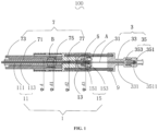
- a delivery system 100 provided by an embodiment I of the present embodiment includes: an outer sheath assembly 1, an inner sheath assembly 3, a sealing assembly 5, a push rod assembly 7, a guide rod 9 and a sheath tube (not shown in the FIG. 1 ).
- the sheath tube is used for at least receiving distal ends of the outer sheath assembly 1, the inner sheath assembly 3, and the push rod assembly 7.
- the outer sheath assembly 1 includes an outer sheath core tube 11, a proximal releaser 13 and a second connecting component 15.
- the outer sheath core tube 11 is fixed to the proximal releaser 13 by the second connecting component 15.
- the outer sheath core tube 11, the proximal releaser 13 and the second connecting component 15 are assembled to form an integral structure.
- the outer sheath core tube 11 includes an inner tube 111 and an outer tube 113 sleeving outside the inner tube 111. Hardness of the outer tube 113 is larger than that of the inner tube 111. An axial length of the inner tube 111 is roughly the same as that of the outer tube 113.
- the inner tube 111 may be a PI tube; the outer tube 113 is a stainless steel tube; and the inner tube 111 is fixedly connected to the outer tube 113 in an adhesion way. Specifically, the inner tube 111 is adhered into the outer tube 113 by glue.
- the outer tube 113 sleeving outside the inner tube 111 may effectively protect the inner tube 111 due to its larger hardness than the inner tube 111, so as to avoid a deformation of the inner tube 111 due to excessive force from the second connecting component 15 in grasping the outer sheath core tube 11.
- a mounting hole 131 used for storing the second connecting component 15 is formed in a proximal end of the proximal releaser 13.
- a shape of the mounting hole 131 corresponds to that of the second connecting component 15. Threads used for connection are formed in an inner wall of the mounting hole 131.
- the second connecting component 15 includes an outer core lock 153 and an outer core grasper 151. External threads connected to the inner wall of the mounting hole 131 are formed in a distal end of the outer core lock 153.
- the distal end of the outer core lock 153 is mounted in the mounting hole 131 of the proximal releaser 13.
- the outer core lock 153 is in threaded connection with the proximal releaser 13.
- a through hole 1531 is formed in the outer core lock 153 in an axial direction.
- a proximal end of the outer core grasper 151 is inserted into the through hole 1531 of the outer core lock 153.
- the outer core grasper 151 is capable of axially moving relative to the outer core lock 153.
- a jaw 1511 is arranged at a distal end of the outer core grasper 151, and may deform under external force.
- the outer core grasper 151 sleeves outside the outer sheath core tube 11.
- the jaw 1511 grasps the outer tube 113.
- Inner walls of the outer core lock 153 and the proximal releaser 13 are both provided with an inclined surface making a contact with the jaw 1511.
- the outer core lock 153 drives the outer core grasper 151 to fix the outer sheath core tube 11 to the proximal releaser 13. Specifically, when the outer core lock 153 is axially screwed into the proximal releaser 13, the outer core lock 153 and the proximal releaser 13 make a contact with the jaw 1511, respectively.
- the outer core lock 153 and the proximal releaser 13 apply radial force to the jaw 1511.
- the jaw 1511 firmly grasps the outer tube 113.
- the inner sheath assembly 3 includes an inner sheath core 31, a rear connecting piece 33 and a first connecting component 35.
- the inner sheath core 31 is fixed to the rear connecting piece 33 by the first connecting component 35.
- the inner sheath core 31, the rear connecting piece 33 and the first connecting component 35 are assembled to form an integral structure.
- the inner sheath core 31 is arranged in the outer sheath core tube 11 in a penetrating manner.
- An axial length of the inner sheath core 31 is larger than that of the outer sheath core tube 11.
- the outer sheath core tube 11 sleeves outside a part of the inner sheath core 31.
- a through hole 331 penetrating in the axial direction is formed in the rear connecting piece 33.
- the inner sheath core 31 is arranged in the through hole 331 in a penetrating manner.
- the rear connecting piece 33 is fixedly connected to the first connecting component 35.
- a connection way between the rear connecting piece 33 and the first connecting component 35 is the same as that between the proximal releaser 13 and the second connecting component 15 in the outer sheath assembly 1.
- a proximal end of the rear connecting piece 33 is in threaded connection with the first connecting component 35.
- the first connecting component 35 includes a Luer lock 351 and an inner core grasper 353.
- a proximal sealing piece 3511 is mounted in the Luer lock 351, and is arranged at a proximal end of the first connecting component 35.
- the proximal sealing piece 3511 may provide a sealing effect for a pre-surgery exhaust operation.
- External threads connected to the rear connecting piece 33 are formed in a distal end of the Luer lock 351.
- the distal end of the Luer lock 351 is inserted into the proximal end of the rear connecting piece 33.
- the Luer lock 351 is in threaded connection with the rear connecting piece 33.
- a shape, a fixing way and a working principle of the inner core grasper 353 are the same as those of the outer core grasper 151.
- a proximal end of the inner core grasper 353 is inserted into the Luer lock 351.
- the inner core grasper 353 is capable of axially moving relative to the Luer lock 351.
- a jaw that may deform under the external force is arranged at a distal end of the inner core grasper 353.
- the inner core grasper 353 sleeves outside the inner sheath core 31.
- the jaw grasps the inner sheath core 31.
- Inner walls of the Luer lock 351 and the rear connecting piece 33 are both provided with an inclined surface making a contact with the jaw.
- the sealing assembly 5 includes a first sealing piece 51.
- the first sealing piece 51 is arranged between the inner sheath core 31 and the outer sheath core tube 11.
- the first sealing piece 51 is used for sealing a gap between a proximal end of the outer sheath core tube 11 and the inner sheath core 31, so as to avoid blood from flowing out along the gap between the outer sheath core tube 11 and the inner sheath core 31 during a surgery.
- the first sealing piece 51 extends in a length direction of the outer sheath core tube 11. At least part of the first sealing piece 51 is arranged between the outer sheath core tube 11 and the inner sheath core 31.
- the first sealing piece 51 may be of a plurality of structures.
- the first sealing piece 51 includes at least one sealing ring 51a.
- the sealing ring 51a is arranged between the outer sheath core tube 11 and the inner sheath core 31.
- the sealing ring 51a is arranged between an outer wall of the inner sheath core 31 and an inner wall of the inner tube 111.
- the sealing ring 51a is connected to the inner sheath core 31 or the outer sheath core tube 11.
- the sealing ring 51a is fixedly connected to the inner sheath core 31 by gluing or welding or in other ways.
- a plurality of sealing rings 51a are arranged in the embodiment. Axial lengths of the plurality of sealing rings 51a are smaller than the axial length of the inner sheath core 31.
- the plurality of sealing rings 51a discontinuously extend in the length direction of the outer sheath core tube 11.
- the sealing rings 51a sleeve outside the inner sheath core 31.
- the plurality of sealing rings 51a are arranged in an axial direction of the inner sheath core 31. Outside diameter dimensions of the plurality of sealing rings 51a change regularly. Specifically, from a distal end of the inner sheath core 31 to a proximal end of the inner sheath core 31, radial distances between the sealing rings 51a and the outer sheath core tube 11 are gradually decreased. That is, from the distal end of the inner sheath core 31 to the proximal end of the inner sheath core 31, outer walls of the sealing rings 51a gradually approach an inner wall of the outer sheath core tube 11. As shown in FIG.
- an inside diameter of the outer sheath core tube 11 is d.
- Three sealing rings 51a are sequentially arranged from a distal end of the outer sheath core tube 11 to the proximal end of the outer sheath core tube 11. Outside diameters of the three sealing rings 51a are an outside diameter d1, an outside diameter d2, and an outside diameter d3.
- An inside diameter d of the outer sheath core tube 11, and the outside diameter d1, the outside diameter d2, and the outside diameter d3 of the three sealing rings 51a satisfy the following relationship: ⁇ d > ⁇ d 3 > ⁇ d 2 > ⁇ d 1
- the outside diameter d1, the outside diameter d2, and the outside diameter d3 of the three sealing rings 51a are gradually increased, but always smaller than the inside diameter d of the outer sheath core tube 11.
- Gaps between the outer walls of the sealing rings 51a and the inner wall of the outer sheath core tube 11 are gradually decreased. There is a certain interval between every two sealing rings 51a.
- the purpose of this design is that if the blood flows through the first sealing ring 51a with the outside diameter d1, a blood flow volume is decreased by resistance due to decrease in the gap. After the blood flow passes through a normal gap section, pressure of the blood flow is decreased at this time; and then after the blood passes through a next sealing ring 51a with a smaller gap, the blood flow volume and the pressure of the blood flow are further decreased. Through obstruction of the plurality of different sealing rings 51a, the blood flow volume and the pressure of the blood flow are gradually decreased, so as to achieve the sealing effect.
- such sealing structure can not only achieve the good sealing effect, but also not significantly strengthen resistance on axial movement of the outer sheath core tube 11 relative to the inner sheath core 31.
- the push rod assembly 7 includes a push rod 71, a push rod joint 73, a third connecting component 75 and a rear handle 77.
- the outer sheath core tube 11 is arranged in the push rod 71 in a penetrating manner.
- An axial length of the push rod 71 is larger than that of the outer sheath core tube 11.
- the push rod joint 73 sleeves outside the push rod 71.
- An axial length of the push rod joint 73 is smaller than that of the push rod 71.
- a connecting structure fixed with the third connecting component 75 is arranged at a proximal end of the push rod joint 73.
- a threaded structure for connection is arranged at the proximal end of the push rod joint 73.
- the third connecting component 75 sleeves outside the push rod 71.
- An axial length of the third connecting component 75 is smaller than that of the push rod 71.
- External threads fitted to the push rod joint 73 are formed in the third connecting component 75.
- the third connecting component 75 is screwed into the push rod joint 73, and is in threaded connection with the push rod joint 73 to form an outer sleeve.
- An axial length of the outer sleeve is roughly the same as that of the push rod 71.
- a proximal end of the push rod 71 is inserted into the third connecting component 75.
- the proximal end of the push rod 71 is fixedly connected to an inner wall of the third connecting component 75.
- the push rod 71 is fixed to the push rod joint 73 by the third connecting component 75.
- the push rod 71, the push rod joint 73 and the third connecting component 75 are assembled to form an integral structure.
- the rear handle 77 includes an accommodating cavity.
- the push rod 71, the push rod joint 73 and the third connecting component 75 are arranged in the accommodating cavity of the rear handle 77.
- the rear handle 77 is connected to the third connecting component 75.
- a proximal end of the third connecting component 75 and the proximal end of the push rod 71 are both abutted to the rear handle 77.
- the guide rod 9 is used for connecting the outer sheath assembly 1, the inner sheath assembly 3 and the push rod assembly 7.
- a proximal end of the guide rod 9 is inserted into the rear connecting piece 33 of the inner sheath assembly 3, and is fixedly mounted in the rear connecting piece 33.
- a middle part of the guide rod 9 is arranged in the proximal releaser 13 of the outer sheath assembly 1 in a penetrating manner.
- the proximal releaser 13 is assembled on the guide rod 9. Under the external force, the proximal releaser 13 may slide in an axial direction of the guide rod 9.
- a distal end of the guide rod 9 is inserted into the rear handle 77 of the push rod assembly 7, and is fixedly mounted in the rear handle 77.
- the rear handle 77 is fixedly connected to the rear connecting piece 33 by the guide rod 9.
- a delivery system 100 provided by an embodiment II of the present embodiment includes: an outer sheath assembly 1, an inner sheath assembly 3, a first sealing piece 51, a push rod assembly 7, and a guide rod 9.
- the embodiment II is different from the embodiment I mainly in a specific structure of the first sealing piece 51.
- the first sealing piece 51 includes a sealing tube 51b.
- the sealing tube 51b is arranged in an outer sheath core tube 11 in a penetrating manner, and extends continuously in a length direction of the outer sheath core tube 11.
- the sealing tube 5 1b is arranged between an outer wall of an inner sheath core 31 and an inner wall of an inner tube 111.
- a guide piece 511b is arranged at a distal end of the sealing tube 51b, and is used for introducing blood flow into a space between the inner sheath core 31 and the sealing tube 51b.
- the guide piece 511b is in a shape of a horn mouth. From the distal end of the sealing tube 51b to a proximal end of the sealing tube 51b, an inside diameter of the guide piece 511b is gradually decreased.
- a diameter of a distal end of the guide piece 511b is d1
- an outside diameter of the sealing tube 51b is d2
- an inside diameter of the outer sheath core tube 11 is d, where the inside diameter d of the outer sheath core tube 11, the diameter d1 of the distal end of the guide piece 511b, and the outside diameter d2 of the sealing tube 51b satisfy the following relationship: ⁇ d 1 > ⁇ d > ⁇ d 2 , and ⁇ d 1 ⁇ 1.5 ⁇ d 2
- the distal end of the guide piece 511b is in interference fitting to the outer sheath core tube 11.
- the diameter d1 of the distal end of the guide piece 511b should be slightly larger than the inside diameter d of the outer sheath core tube 11, but it should not be too large, which may lead to difficulty of assembly and strengthen resistance on axial movement of the outer sheath core tube 11.
- the outside diameter d2 of the sealing tube 51b should be smaller than the inside diameter d of the outer sheath core tube 11, so that the outer sheath core tube 11 can move smoothly in an axial direction.
- the proximal end of the sealing tube 5 1b is connected to a proximal end of the inner sheath core 31.
- Hardness of the sealing tube 51b is larger than that of silica gel; and the distal end of the guide piece 511b makes a line contact with an inner cavity of the outer sheath core tube 11 to form interference fitting, thereby improving support force and sealing performance of the guide piece 511b to the outer sheath core tube 11, and avoiding the distal end of the guide piece 511b from being squeezed to deform to weaken flow guide efficiency.
- the distal end of the sealing tube 51b is in interference fitting to the outer sheath core tube 11.
- the proximal end of the sealing tube 51b penetrates through a rear connecting piece 33 to be in sealing connection with a proximal sealing piece 3511 of a first connecting component 35.
- the proximal end of the sealing tube 51b penetrates through the rear connecting piece 33 to be inserted into the proximal sealing piece 3511.
- the blood flow is introduced into a gap between the inner sheath core 31 and the inner cavity of the sealing tube 51b by the guide piece 511b of the sealing tube 51b.
- the sealing tube 51b and the inner sheath core 31 are relatively static components in the delivery system 100.
- a tail end of the sealing tube 51b is inserted into the proximal sealing piece 3511, so as to achieve a sealing effect.
- the proximal sealing piece 3511 can not only seal proximal blood flow, but also further meet requirements for exhaust of the inner sheath core 31.
- the proximal end of the sealing tube 51b may also be fixedly connected to the proximal end of the inner sheath core 31 by gluing or welding or in other ways.
- the design of the sealing tube 51b is to introduce the blood flow from a lumen of the outer sheath assembly 1 into a lumen formed between the inner sheath assembly 3 and the sealing tube 51b in a drainage way, which can not only avoid the blood from flowing out from a proximal end of the outer sheath assembly 1, but also achieve the purpose of simplifying the sealing structure.
- the horn mouth design of the guide piece 511b can not only achieve sealing by line contact, but also weaken movement resistance, strengthened by sealing, of the outer sheath assembly 1 to the maximum while achieving the good sealing effect.
- a delivery system 100 provided by an embodiment III of the present embodiment includes: an outer sheath assembly 1, an inner sheath assembly 3, a first sealing piece 51, a push rod assembly 7, and a guide rod 9.
- the embodiment III is different from the embodiment I mainly in a specific structure of the first sealing piece 51.
- an outer sheath core tube 11 is fixed to a proximal releaser 13 by a second connecting component 15.
- a cavity 17 facilitating adjustment on a proximal position of the outer sheath core tube 11 is formed between the proximal releaser 13 and the second connecting component 15.
- the cavity 17 is located between the proximal releaser 13 and an outer core lock 153.
- a first sealing piece 51 is capable of sealing the cavity 17.
- first sealing pieces 51 are arranged.
- the two first sealing pieces 51 are close to or located at a distal end of the proximal releaser 13 and a proximal end of the outer core lock 153 respectively.
- one first sealing piece 51 is a proximal releaser sealing gasket 51c arranged at the distal end of the proximal releaser 13.
- the other first sealing piece 51 is an outer core lock sealing gasket 51d arranged at the proximal end of the outer core lock 153. It is to be understood that, in other embodiments, three, four or more first sealing pieces 51 may also be arranged, and the number may be set as actually needed.
- a completely closed inner cavity is formed between the proximal releaser 13 and the outer core lock 153.
- the outer core lock sealing gasket 51d is positioned by the outer core grasper 151 and an end surface of an inner cavity of the outer core lock 153, so as to avoid the outer core lock sealing gasket 51d from moving in an axial direction.
- a braided mesh tube or a spring tube is arranged in a tube wall of a sheath tube receiving the outer sheath core tube 11, the sheath tube needs to be machined by the steps of cleaning, coating with a hydrophilic coating, etc.
- the sheath tube may be shortened or elongated, so that the shortened or elongated sheath tube needs to use the outer sheath core tube 11 of different lengths. Also because the length of the outer sheath core tube 11 used by the sheath tube of the same length specification is generally a fixed value, it is also unlikely to truncate or stretch the outer sheath core tube 11, thereby lowering a matching degree between the outer sheath core tube 11 and the sheath tube.
- a sufficient space for an axial change of the outer sheath core tube 11 is reserved in the inner cavity enclosed by the proximal releaser 13 and the outer core lock 153, thereby achieving the purpose of adapting to these micro-deformed sheath tubes, improving the assembly accuracy of the delivery system, and simplifying assembly steps.
- the blood flow may only enter a gap between the outer core grasper 151 and the outer sheath core tube 11. Just because of the presence of the proximal releaser sealing gasket 51c and the outer core lock sealing gasket 51d, the blood can only flow in a sealed cavity formed between the two sealing gaskets 51d and 51c, and no longer flows outside from the proximal end of the outer sheath core tube 11.
- the proximal releaser sealing gasket 51c is located near the distal end of the outer core grasper 151, and is fitted to the outer sheath core tube 11.
- the proximal releaser sealing gasket 51c sleeves the outer sheath core tube 11.
- the inside diameter of the proximal releaser sealing gasket 51c should not be too large or too small. If it is too large, it is prone to strengthening resistance on axial movement of the outer sheath core tube 11; and if it is too small, it may lead to a poor sealing effect.
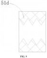
- a selected structure of the outer core lock sealing gasket 51d may be a serrated surface as shown in FIG. 9 , or an arc surface as shown in FIG. 10 .
- outer core lock sealing gasket 51d makes line contact with the inner sheath core 31.
- the resistance caused by the outer core lock sealing gasket 51d on the inner sheath core 31 may be weakened while the sealing effect is achieved.
- a delivery system 100 provided by an embodiment IV of the present embodiment is different from the embodiment I in that: a sealing assembly 5 further includes a second sealing piece 53 in addition to a first sealing piece (not shown in the FIG. 11 ).
- the first sealing piece may be of a structure of any one of the first sealing pieces 51 in embodiments 1-3, which will not be elaborated here.
- the second sealing piece 53 performs sealing for blood leakage between an outer sheath core tube 11 and an inner cavity of a push rod 71.
- the second sealing piece 53 is capable of sealing a gap between the outer sheath core tube 11 and the push rod 71.
- the second sealing piece 53 may be of a plurality of structures. As shown in FIG. 12 , in the embodiment, the second sealing piece 53 includes at least one bulge 53a.
- the bulge 53a is located between the outer sheath core tube 11 and the push rod 71, so as to decrease the gap between the outer sheath core tube 11 and the push rod 71.
- the bulge 53a is arranged on the push rod 71, and forms an integral structure with the push rod 71.
- the push rod 71 is made of a polymer thermoplastic material. The push rod 71 is heated to shrink to form a shrink mouth which is the bulge 53a.
- the bulge 53a and the push rod 71 may also be separately formed, and then fixedly connected together by gluing or screwing or in other ways.
- a plurality of bulges 53a are arranged in the embodiment.
- the plurality of bulges 53a are arranged in an axial direction of the push rod 71.
- an inside diameter of the push rod is d1
- an outside diameter of the outer sheath core tube 11 is d2.
- three bulges 53a are sequentially arranged from the distal end of the push rod 71 to the proximal end of the push rod 71, having inside diameters of D1, D2 and D3 respectively, where the inside diameter d1 of the push rod, the outside diameter d2 of the outer sheath core tube 11, and the inside diameters D1, D2 and D3 of the three bulges 53a satisfy the following relationship: ⁇ d 1 > ⁇ D 1 > ⁇ D 2 > ⁇ D 3 > ⁇ d 2
- the inside diameters of the bulges 53a are gradually decreased from the distal end of the push rod 71 to the proximal end of the push rod 71. There is a certain interval between every two bulges 53a.
- the purpose of this design is that if a blood flow passes through the first bulge 53a, a blood flow volume is decreased by resistance due to decrease in the gap. After the blood flow passes through a normal gap section, pressure of the blood flow is decreased at this time; and then after the blood passes through a next bulge 53a with a smaller gap, the blood flow volume and the pressure of the blood flow are further decreased. Through obstruction of the plurality of bulges 53a with different inside diameters, the blood flow volume and the pressure of the blood flow are gradually decreased, so as to achieve the sealing effect.
- the method is simple to operate, and easy to realize by arranging the bulges 53a in local positions, and the dimensional accuracy is easy to control.
- Structural design of the bulges 53a only reduces the local gap between the outer sheath core tube 11 and the inner cavity of the push rod 71, which less affects circumferential movement of the outer sheath core tube 11. It will not significantly strengthen resistance on circumferential movement of the outer sheath core tube 11, and there is no newly added part, so that the good sealing effect can be achieved, and the risk of blood leakage is reduced.
- FIG. 13 it is a delivery system 100 provided by embodiment V of the present embodiment, which is different from that in the embodiment IV mainly in a specific structure of a second sealing piece 53.
- a first sealing piece (not shown in the FIG. 13 ) may be of a structure of any one of the first sealing pieces 51 in embodiments 1-3, which will not be elaborated here.
- the second sealing piece 53 is located between an outer sheath core tube 11 and a push rod 71, to be used for blocking a gap between the outer sheath core tube 11 and the inner cavity of the push rod 71.
- a clamping groove 771 with an opening facing a distal end is formed in a rear handle 77, corresponding to the push rod 71.
- the second sealing piece 53 is arranged in the clamping groove 771.
- the second sealing piece 53 includes a push rod sealing gasket 53b.
- the push rod sealing gasket 53b is arranged at a proximal end of the push rod 71.
- the push rod 71 extends out of a proximal edge of a third connecting component 75.
- the push rod sealing gasket 53b sleeves the extended push rod 71.
- the push rod 71 and the push rod sealing gasket 53b are inserted into the clamping groove 771 of the rear handle 77 together.
- the push rod sealing gasket 53b is fixed to the rear handle 77 by the push rod 71.
- a void avoidance groove 531b is formed in a position, close to the third connecting component 75, of the push rod sealing gasket 53b.
- An inside diameter of the void avoidance groove 531b is gradually decreased from a distal end of the outer sheath core tube 11 to a proximal end of the outer sheath core tube 11.
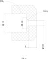
- the push rod sealing gasket 53b needs to satisfy a fitting relationship with the push rod 71, the outer sheath core tube 11 and an inner sheath core 31: an inside diameter D1 of the push rod sealing gasket 53b and an outside diameter d1 of the push rod 71 satisfy the following relationship: ⁇ D 1 ⁇ ⁇ d 1 .
- a maximum inside diameter D2 of the void avoidance groove 531b and the inside diameter d2 of the push rod 71 satisfy the following relationship: ⁇ D 2 > ⁇ d 2
- the maximum inside diameter D2 of the void avoidance groove 531b is larger than the inside diameter d2 of the push rod 71, so as to prevent the situation that the soft push rod sealing gasket 53b is stuck into a gap between the outer sheath core tube 11 and the push rod 71 when the outer sheath core tube 11 axially moves relative to the push rod 71, and then a friction between the above two is strengthened.
- the outside diameter of the outer sheath core tube 11 is larger than or equal to 1.1 times of the inside diameter of the push rod sealing gasket 53b, and is smaller than or equal to 1.5 times of an inner diameter of the push rod sealing gasket 53b. This is because fit between the outside diameter of the outer sheath core tube 11 and a through hole of the push rod sealing gasket 53b cannot be too large or too small. If it is too large, it is easy to strengthen resistance on axial movement of the outer sheath core tube 11; and if it is too small, it may lead to the poor sealing effect.
- the length of the sealing section is larger than or equal to 1 mm, and smaller than or equal to 3 mm. This is because the length of the sealing section of the push rod sealing gasket 53b should not be too small or too large. If it is too small, it may lead to the poor sealing effect; and if it is too large, it may strengthen the resistance on axial movement of the outer sheath core tube 11.
- the gap between the outer sheath core tube 11 and the inner cavity of the push rod 71 may be completely blocked, so as to achieve a complete sealing effect.
- the outer sheath assembly 1 slides in the axial direction of the guide rod 9 under the external force, so as to release a stent.
- the inner sheath core 31 remains stationary during axis movement of the outer sheath core tube 11.
- the blood flowing out along a gap between the outer sheath core tube 11 and the inner sheath core 31 is hindered by the first sealing piece 51, which effectively avoids the blood from flowing out from the proximal end of the outer sheath core tube 11.
- the blood flowing out along the gap between the outer sheath core tube 11 and the inner cavity of the push rod 71 is hindered by the second sealing piece 53, which further avoids the blood from flowing out from the proximal end of the outer sheath core tube 11.
- Sealing performance of the existing delivery system mainly depends on decrease in a gap between the components for sealing.
- the delivery system 100 of the present embodiment solves the problem of blood leakage of a product, can also ensure normal movement of a moving component at the same time, and can allow the length of each component to have a large dimensional tolerance, which reduces tolerance requirements for manufacturing to a certain extent and lowers the production cost.
- a sealing principle between an inner sheath core tube and the outer sheath core tube can also be adopted for sealing between the outer sheath core tube and the push rod as actually needed, so as to achieve sealing between the outer sheath core tube and the push rod; and a sealing principle between the outer sheath core tube and the push rod can also be adopted for sealing between the inner sheath core tube and the outer sheath core tube as actually needed, so as to achieve sealing between the inner and outer sheath core tubes.
Landscapes
- Health & Medical Sciences (AREA)
- Engineering & Computer Science (AREA)
- Biomedical Technology (AREA)
- Life Sciences & Earth Sciences (AREA)
- Animal Behavior & Ethology (AREA)
- Veterinary Medicine (AREA)
- Public Health (AREA)
- Heart & Thoracic Surgery (AREA)
- General Health & Medical Sciences (AREA)
- Transplantation (AREA)
- Vascular Medicine (AREA)
- Oral & Maxillofacial Surgery (AREA)
- Cardiology (AREA)
- Biophysics (AREA)
- Pulmonology (AREA)
- Anesthesiology (AREA)
- Hematology (AREA)
- Surgical Instruments (AREA)
- Media Introduction/Drainage Providing Device (AREA)
- Infusion, Injection, And Reservoir Apparatuses (AREA)
Abstract
Description
- The present embodiments belongs to the technical field of medical instruments, and particularly relates to a delivery system.
- A minimally invasive surgery for vascular repair with a covered stent is widely used for treating aortic vascular diseases due to its minimal injury, rapid recovery and good immediate effects. During clinical implantation, the covered stent is pre-mounted into a sheath tube of a delivery system firstly. Then, the covered stent passes through a human vascular lumen, and is delivered to a lesion location by the sheath tube of the delivery system. Finally, the covered stent is released from the sheath tube of the delivery system. The covered stent isolates a blood flow from the lesion location of a blood vessel, so as to achieve a purpose of treatment. Due to a gap between an outer wall of an inner sheath core and an inner cavity of an outer sheath core tube of the delivery system, blood is liable to leak from the gap, to cause a blood leakage phenomenon during a surgery, which causes a certain damage on a patient.
- An objective of the present disclosure is to provide a delivery system, aiming to solve the technical problem that a blood leakage phenomenon occurs due to poor sealing effects of an existing delivery system, to cause damage on a patient.
- The present disclosure is realized as follows: the delivery system includes an outer sheath assembly, an inner sheath assembly, and a sealing assembly, where the outer sheath assembly includes an outer sheath core tube; the inner sheath assembly includes an inner sheath core arranged in the outer sheath core tube in a penetrating manner; and the sealing assembly includes a first sealing piece, and the first sealing piece is arranged between the inner sheath core and the outer sheath core tube to seal a gap between a proximal end of the outer sheath core tube and the inner sheath core.
- The present disclosure has the beneficial effects that: for the delivery system of the present disclosure, a first sealing piece is arranged between an inner sheath core and an outer sheath core tube. The gap between the proximal end of the outer sheath core tube and the inner sheath core is sealed by the first sealing piece, which can effectively block blood flowing into the gap. Therefore, the blood is avoided from flowing out of a product during a surgery, and the technical problem of blood leakage of the product is solved.
-
-
FIG. 1 is a longitudinal cross-sectional view of a delivery system of an embodiment I; -
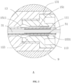
FIG. 2 is a partial enlarged view A inFIG. 1 ; -
FIG. 3 is a partial enlarged view B inFIG. 1 ; -
FIG. 4 is a longitudinal cross-sectional view of a delivery system of an embodiment II ; -
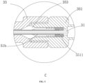
FIG. 5 is a partial enlarged view C inFIG. 4 ; -
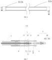
FIG. 6 is a longitudinal cross-sectional view of a sealing tube of an embodiment II; -
FIG. 7 is a longitudinal cross-sectional view of a delivery system of an embodiment III; -
FIG. 8 is a partial enlarged view D inFIG. 7 ; -
FIG. 9 is a longitudinal cross-sectional view I of an outer core lock sealing gasket of the delivery system of the embodiment III; -
FIG. 10 is a longitudinal cross-sectional view II of the outer core lock sealing gasket of the delivery system of the embodiment III; -
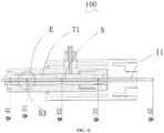
FIG. 11 is a partial longitudinal cross-sectional view of a delivery system of an embodiment IV; -
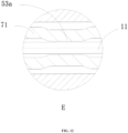
FIG. 12 is a partial enlarged view E inFIG. 11 ; -
FIG. 13 is a partial longitudinal cross-sectional view of a delivery system of an embodiment V; and -
FIG. 14 is a longitudinal cross-sectional view of a push rod sealing gasket of a delivery system of an embodiment V. - 100-delivery system,
- 1-outer sheath assembly,
- 11-outer sheath core tube, 111-inner tube, 113-outer tube,
- 13-proximal releaser, 131-mounting hole,
- 15-second connecting component, 151-outer core grasper, 1511-jaw, 153-outer core lock, 1531-through hole,
- 17-cavity,
- 3-inner sheath assembly,
- 31-inner sheath core,
- 33-rear connecting piece, 331-through hole,
- 35-first connecting component, 351, Luer lock, 3511-proximal sealing piece, 353-inner core grasper,
- 5-sealing assembly,
- 51-first sealing piece, 51a, sealing ring, 51b-sealing tube, 51 1b-guide piece, 51c-proximal releaser sealing gasket, 51d-outer core lock sealing gasket,
- 53-second sealing piece, 53a-bulge, 53b-push rod sealing gasket, 531b- void avoidance groove,
- 7-push rod assembly,
- 71-push rod,
- 73-push rod joint,
- 75-third connecting component,
- 77-rear handle, 771-clamping groove,
- 9-guide rod.
- In order to make the objectives, technical solutions and advantages of the present disclosure clearer, the present disclosure will be further described in detail below in conjunction with the drawings and embodiments. It should be understood that the specific embodiments described herein are merely illustrative of the present disclosure and are not intended to limit the present disclosure.
- It should be noted that when an element is considered to be "fixed" or "arranged" to another element, the element may be directly arranged on another element or there may be intermediate element simultaneously. When an element is considered to be "connected" to another element, the element may be directly connected to another element or there may be an intermediate element simultaneously.
- It should also be noted that the left, right, upper, lower and other orientation terms in the embodiments are only relative concepts or refer to the normal use status of the product, and should not be considered as limiting.
- It should be noted that in the field of invasive medical instruments, it is general to refer one end, closer to an operator, of a medical instrument implanted into a human body or an animal body to as the "proximal end", and one end farther from the operator to as the "distal end". Based on this principle, the "proximal end" and the "distal end" of any component of the medical instrument are defined. An "axial direction" generally refers to a length direction of the medical instrument when it is delivered; and a "radial direction" generally refers to a direction perpendicular to the "axial direction" of the medical instrument. Based on this principle, the "axial direction" and the "radial direction" of any component of the medical instrument are defined.
- As shown in
FIG. 1 , adelivery system 100 provided by an embodiment I of the present embodiment includes: anouter sheath assembly 1, aninner sheath assembly 3, asealing assembly 5, apush rod assembly 7, aguide rod 9 and a sheath tube (not shown in theFIG. 1 ). The sheath tube is used for at least receiving distal ends of theouter sheath assembly 1, theinner sheath assembly 3, and thepush rod assembly 7. - The
outer sheath assembly 1 includes an outersheath core tube 11, aproximal releaser 13 and a second connectingcomponent 15. The outersheath core tube 11 is fixed to theproximal releaser 13 by the second connectingcomponent 15. The outersheath core tube 11, theproximal releaser 13 and the second connectingcomponent 15 are assembled to form an integral structure. - As shown in
FIGS. 1 and2 , in the embodiment, the outersheath core tube 11 includes aninner tube 111 and anouter tube 113 sleeving outside theinner tube 111. Hardness of theouter tube 113 is larger than that of theinner tube 111. An axial length of theinner tube 111 is roughly the same as that of theouter tube 113. In the embodiment, theinner tube 111 may be a PI tube; theouter tube 113 is a stainless steel tube; and theinner tube 111 is fixedly connected to theouter tube 113 in an adhesion way. Specifically, theinner tube 111 is adhered into theouter tube 113 by glue. Theouter tube 113 sleeving outside theinner tube 111 may effectively protect theinner tube 111 due to its larger hardness than theinner tube 111, so as to avoid a deformation of theinner tube 111 due to excessive force from the second connectingcomponent 15 in grasping the outersheath core tube 11. - A mounting
hole 131 used for storing the second connectingcomponent 15 is formed in a proximal end of theproximal releaser 13. A shape of the mountinghole 131 corresponds to that of the second connectingcomponent 15. Threads used for connection are formed in an inner wall of the mountinghole 131. - The second connecting
component 15 includes anouter core lock 153 and anouter core grasper 151. External threads connected to the inner wall of the mountinghole 131 are formed in a distal end of theouter core lock 153. The distal end of theouter core lock 153 is mounted in the mountinghole 131 of theproximal releaser 13. Theouter core lock 153 is in threaded connection with theproximal releaser 13. A throughhole 1531 is formed in theouter core lock 153 in an axial direction. A proximal end of theouter core grasper 151 is inserted into the throughhole 1531 of theouter core lock 153. Theouter core grasper 151 is capable of axially moving relative to theouter core lock 153. Ajaw 1511 is arranged at a distal end of theouter core grasper 151, and may deform under external force. Theouter core grasper 151 sleeves outside the outersheath core tube 11. Thejaw 1511 grasps theouter tube 113. Inner walls of theouter core lock 153 and theproximal releaser 13 are both provided with an inclined surface making a contact with thejaw 1511. Theouter core lock 153 drives theouter core grasper 151 to fix the outersheath core tube 11 to theproximal releaser 13. Specifically, when theouter core lock 153 is axially screwed into theproximal releaser 13, theouter core lock 153 and theproximal releaser 13 make a contact with thejaw 1511, respectively. Theouter core lock 153 and theproximal releaser 13 apply radial force to thejaw 1511. Thejaw 1511 firmly grasps theouter tube 113. - As shown in
FIG. 1 , theinner sheath assembly 3 includes aninner sheath core 31, arear connecting piece 33 and a first connectingcomponent 35. Theinner sheath core 31 is fixed to the rear connectingpiece 33 by the first connectingcomponent 35. Theinner sheath core 31, therear connecting piece 33 and the first connectingcomponent 35 are assembled to form an integral structure. - The
inner sheath core 31 is arranged in the outersheath core tube 11 in a penetrating manner. An axial length of theinner sheath core 31 is larger than that of the outersheath core tube 11. The outersheath core tube 11 sleeves outside a part of theinner sheath core 31. - A through
hole 331 penetrating in the axial direction is formed in the rear connectingpiece 33. Theinner sheath core 31 is arranged in the throughhole 331 in a penetrating manner. The rear connectingpiece 33 is fixedly connected to the first connectingcomponent 35. In the embodiment, a connection way between the rear connectingpiece 33 and the first connectingcomponent 35 is the same as that between theproximal releaser 13 and the second connectingcomponent 15 in theouter sheath assembly 1. A proximal end of the rear connectingpiece 33 is in threaded connection with the first connectingcomponent 35. - The first connecting
component 35 includes aLuer lock 351 and aninner core grasper 353. Aproximal sealing piece 3511 is mounted in theLuer lock 351, and is arranged at a proximal end of the first connectingcomponent 35. Theproximal sealing piece 3511 may provide a sealing effect for a pre-surgery exhaust operation. External threads connected to the rear connectingpiece 33 are formed in a distal end of theLuer lock 351. The distal end of theLuer lock 351 is inserted into the proximal end of the rear connectingpiece 33. TheLuer lock 351 is in threaded connection with the rear connectingpiece 33. A shape, a fixing way and a working principle of theinner core grasper 353 are the same as those of theouter core grasper 151. A proximal end of theinner core grasper 353 is inserted into theLuer lock 351. Theinner core grasper 353 is capable of axially moving relative to theLuer lock 351. A jaw that may deform under the external force is arranged at a distal end of theinner core grasper 353. Theinner core grasper 353 sleeves outside theinner sheath core 31. The jaw grasps theinner sheath core 31. Inner walls of theLuer lock 351 and the rear connectingpiece 33 are both provided with an inclined surface making a contact with the jaw. When theLuer lock 351 is screwed into the rear connectingpiece 33 in an axial direction, theLuer lock 351 and the rear connectingpiece 33 apply radial force to the jaw, and the jaw firmly grasps theinner sheath core 31. Theinner sheath core 31 is fixed to the rear connectingpiece 33 by the first connectingcomponent 35. - As shown in
FIGS. 1-3 , in the embodiment, the sealingassembly 5 includes afirst sealing piece 51. Thefirst sealing piece 51 is arranged between theinner sheath core 31 and the outersheath core tube 11. Thefirst sealing piece 51 is used for sealing a gap between a proximal end of the outersheath core tube 11 and theinner sheath core 31, so as to avoid blood from flowing out along the gap between the outersheath core tube 11 and theinner sheath core 31 during a surgery. Thefirst sealing piece 51 extends in a length direction of the outersheath core tube 11. At least part of thefirst sealing piece 51 is arranged between the outersheath core tube 11 and theinner sheath core 31. - The
first sealing piece 51 may be of a plurality of structures. In the embodiment, thefirst sealing piece 51 includes at least onesealing ring 51a. The sealingring 51a is arranged between the outersheath core tube 11 and theinner sheath core 31. Specifically, the sealingring 51a is arranged between an outer wall of theinner sheath core 31 and an inner wall of theinner tube 111. The sealingring 51a is connected to theinner sheath core 31 or the outersheath core tube 11. In the embodiment, the sealingring 51a is fixedly connected to theinner sheath core 31 by gluing or welding or in other ways. In order to improve the sealing effect, a plurality of sealingrings 51a are arranged in the embodiment. Axial lengths of the plurality of sealingrings 51a are smaller than the axial length of theinner sheath core 31. The plurality of sealingrings 51a discontinuously extend in the length direction of the outersheath core tube 11. - The sealing rings 51a sleeve outside the
inner sheath core 31. The plurality of sealingrings 51a are arranged in an axial direction of theinner sheath core 31. Outside diameter dimensions of the plurality of sealingrings 51a change regularly. Specifically, from a distal end of theinner sheath core 31 to a proximal end of theinner sheath core 31, radial distances between the sealing rings 51a and the outersheath core tube 11 are gradually decreased. That is, from the distal end of theinner sheath core 31 to the proximal end of theinner sheath core 31, outer walls of the sealing rings 51a gradually approach an inner wall of the outersheath core tube 11. As shown inFIG. 1 , an inside diameter of the outersheath core tube 11 is d. Three sealingrings 51a are sequentially arranged from a distal end of the outersheath core tube 11 to the proximal end of the outersheath core tube 11. Outside diameters of the three sealingrings 51a are an outside diameter d1, an outside diameter d2, and an outside diameter d3. An inside diameter d of the outersheath core tube 11, and the outside diameter d1, the outside diameter d2, and the outside diameter d3 of the three sealingrings 51a satisfy the following relationship:
- The outside diameter d1, the outside diameter d2, and the outside diameter d3 of the three sealing
rings 51a are gradually increased, but always smaller than the inside diameter d of the outersheath core tube 11. - Gaps between the outer walls of the sealing rings 51a and the inner wall of the outer
sheath core tube 11 are gradually decreased. There is a certain interval between every two sealingrings 51a. The purpose of this design is that if the blood flows through thefirst sealing ring 51a with the outside diameter d1, a blood flow volume is decreased by resistance due to decrease in the gap. After the blood flow passes through a normal gap section, pressure of the blood flow is decreased at this time; and then after the blood passes through anext sealing ring 51a with a smaller gap, the blood flow volume and the pressure of the blood flow are further decreased. Through obstruction of the plurality ofdifferent sealing rings 51a, the blood flow volume and the pressure of the blood flow are gradually decreased, so as to achieve the sealing effect. By decreasing the gaps between local positions of the outersheath core tube 11 and theinner sheath core 31, such sealing structure can not only achieve the good sealing effect, but also not significantly strengthen resistance on axial movement of the outersheath core tube 11 relative to theinner sheath core 31. - As shown in
FIG. 1 , thepush rod assembly 7 includes apush rod 71, a push rod joint 73, a third connectingcomponent 75 and arear handle 77. - The outer
sheath core tube 11 is arranged in thepush rod 71 in a penetrating manner. An axial length of thepush rod 71 is larger than that of the outersheath core tube 11. - The push rod joint 73 sleeves outside the
push rod 71. An axial length of the push rod joint 73 is smaller than that of thepush rod 71. A connecting structure fixed with the third connectingcomponent 75 is arranged at a proximal end of the push rod joint 73. Usually, a threaded structure for connection is arranged at the proximal end of the push rod joint 73. - The third connecting
component 75 sleeves outside thepush rod 71. An axial length of the third connectingcomponent 75 is smaller than that of thepush rod 71. External threads fitted to the push rod joint 73 are formed in the third connectingcomponent 75. The third connectingcomponent 75 is screwed into the push rod joint 73, and is in threaded connection with the push rod joint 73 to form an outer sleeve. An axial length of the outer sleeve is roughly the same as that of thepush rod 71. - A proximal end of the
push rod 71 is inserted into the third connectingcomponent 75. The proximal end of thepush rod 71 is fixedly connected to an inner wall of the third connectingcomponent 75. Thepush rod 71 is fixed to the push rod joint 73 by the third connectingcomponent 75. Thepush rod 71, the push rod joint 73 and the third connectingcomponent 75 are assembled to form an integral structure. - The
rear handle 77 includes an accommodating cavity. Thepush rod 71, the push rod joint 73 and the third connectingcomponent 75 are arranged in the accommodating cavity of therear handle 77. Therear handle 77 is connected to the third connectingcomponent 75. A proximal end of the third connectingcomponent 75 and the proximal end of thepush rod 71 are both abutted to therear handle 77. - As shown in
FIG. 1 , theguide rod 9 is used for connecting theouter sheath assembly 1, theinner sheath assembly 3 and thepush rod assembly 7. A proximal end of theguide rod 9 is inserted into the rear connectingpiece 33 of theinner sheath assembly 3, and is fixedly mounted in the rear connectingpiece 33. A middle part of theguide rod 9 is arranged in theproximal releaser 13 of theouter sheath assembly 1 in a penetrating manner. Theproximal releaser 13 is assembled on theguide rod 9. Under the external force, theproximal releaser 13 may slide in an axial direction of theguide rod 9. A distal end of theguide rod 9 is inserted into therear handle 77 of thepush rod assembly 7, and is fixedly mounted in therear handle 77. Therear handle 77 is fixedly connected to the rear connectingpiece 33 by theguide rod 9. - As shown in
FIG. 4 , adelivery system 100 provided by an embodiment II of the present embodiment includes: anouter sheath assembly 1, aninner sheath assembly 3, afirst sealing piece 51, apush rod assembly 7, and aguide rod 9. The embodiment II is different from the embodiment I mainly in a specific structure of thefirst sealing piece 51. - As shown in
FIGS. 4 and6 , in the embodiment, thefirst sealing piece 51 includes a sealingtube 51b. The sealingtube 51b is arranged in an outersheath core tube 11 in a penetrating manner, and extends continuously in a length direction of the outersheath core tube 11. The sealingtube 5 1b is arranged between an outer wall of aninner sheath core 31 and an inner wall of aninner tube 111. - A
guide piece 511b is arranged at a distal end of the sealingtube 51b, and is used for introducing blood flow into a space between theinner sheath core 31 and the sealingtube 51b. Theguide piece 511b is in a shape of a horn mouth. From the distal end of the sealingtube 51b to a proximal end of the sealingtube 51b, an inside diameter of theguide piece 511b is gradually decreased. Specifically, a diameter of a distal end of theguide piece 511b is d1, an outside diameter of the sealingtube 51b is d2, and an inside diameter of the outersheath core tube 11 is d, where the inside diameter d of the outersheath core tube 11, the diameter d1 of the distal end of theguide piece 511b, and the outside diameter d2 of the sealingtube 51b satisfy the following relationship:
- The distal end of the
guide piece 511b is in interference fitting to the outersheath core tube 11. The diameter d1 of the distal end of theguide piece 511b should be slightly larger than the inside diameter d of the outersheath core tube 11, but it should not be too large, which may lead to difficulty of assembly and strengthen resistance on axial movement of the outersheath core tube 11. The outside diameter d2 of the sealingtube 51b should be smaller than the inside diameter d of the outersheath core tube 11, so that the outersheath core tube 11 can move smoothly in an axial direction. - The proximal end of the sealing
tube 5 1b is connected to a proximal end of theinner sheath core 31. Hardness of the sealingtube 51b is larger than that of silica gel; and the distal end of theguide piece 511b makes a line contact with an inner cavity of the outersheath core tube 11 to form interference fitting, thereby improving support force and sealing performance of theguide piece 511b to the outersheath core tube 11, and avoiding the distal end of theguide piece 511b from being squeezed to deform to weaken flow guide efficiency. - As shown in
FIGS. 4 and5 , the distal end of the sealingtube 51b is in interference fitting to the outersheath core tube 11. The proximal end of the sealingtube 51b penetrates through a rear connectingpiece 33 to be in sealing connection with aproximal sealing piece 3511 of a first connectingcomponent 35. Specifically, the proximal end of the sealingtube 51b penetrates through the rear connectingpiece 33 to be inserted into theproximal sealing piece 3511. - In the embodiment, when the blood flows to the
guide piece 511b, a pathway is not blocked. Instead, the blood flow is introduced into a gap between theinner sheath core 31 and the inner cavity of the sealingtube 51b by theguide piece 511b of the sealingtube 51b. The sealingtube 51b and theinner sheath core 31 are relatively static components in thedelivery system 100. A tail end of the sealingtube 51b is inserted into theproximal sealing piece 3511, so as to achieve a sealing effect. In the embodiment, theproximal sealing piece 3511 can not only seal proximal blood flow, but also further meet requirements for exhaust of theinner sheath core 31. In other embodiments, the proximal end of the sealingtube 51b may also be fixedly connected to the proximal end of theinner sheath core 31 by gluing or welding or in other ways. - The design of the sealing
tube 51b is to introduce the blood flow from a lumen of theouter sheath assembly 1 into a lumen formed between theinner sheath assembly 3 and the sealingtube 51b in a drainage way, which can not only avoid the blood from flowing out from a proximal end of theouter sheath assembly 1, but also achieve the purpose of simplifying the sealing structure. In addition, the horn mouth design of theguide piece 511b can not only achieve sealing by line contact, but also weaken movement resistance, strengthened by sealing, of theouter sheath assembly 1 to the maximum while achieving the good sealing effect. - As shown in
FIG. 7 , adelivery system 100 provided by an embodiment III of the present embodiment includes: anouter sheath assembly 1, aninner sheath assembly 3, afirst sealing piece 51, apush rod assembly 7, and aguide rod 9. The embodiment III is different from the embodiment I mainly in a specific structure of thefirst sealing piece 51. - As shown in
FIGS. 7 and8 , in the embodiment, an outersheath core tube 11 is fixed to aproximal releaser 13 by a second connectingcomponent 15. Acavity 17 facilitating adjustment on a proximal position of the outersheath core tube 11 is formed between theproximal releaser 13 and the second connectingcomponent 15. Thecavity 17 is located between theproximal releaser 13 and anouter core lock 153. In the embodiment, afirst sealing piece 51 is capable of sealing thecavity 17. - In the embodiment, two
first sealing pieces 51 are arranged. The twofirst sealing pieces 51 are close to or located at a distal end of theproximal releaser 13 and a proximal end of theouter core lock 153 respectively. Specifically, onefirst sealing piece 51 is a proximalreleaser sealing gasket 51c arranged at the distal end of theproximal releaser 13. The otherfirst sealing piece 51 is an outer corelock sealing gasket 51d arranged at the proximal end of theouter core lock 153. It is to be understood that, in other embodiments, three, four or morefirst sealing pieces 51 may also be arranged, and the number may be set as actually needed. - By additionally arranging the proximal
releaser sealing gasket 51c and the outer corelock sealing gasket 51d, a completely closed inner cavity is formed between theproximal releaser 13 and theouter core lock 153. The outer corelock sealing gasket 51d is positioned by theouter core grasper 151 and an end surface of an inner cavity of theouter core lock 153, so as to avoid the outer corelock sealing gasket 51d from moving in an axial direction. As a braided mesh tube or a spring tube is arranged in a tube wall of a sheath tube receiving the outersheath core tube 11, the sheath tube needs to be machined by the steps of cleaning, coating with a hydrophilic coating, etc. before being assembled with the outersheath core tube 11, theinner sheath core 31 and other elements together. In these machining processes, the sheath tube may be shortened or elongated, so that the shortened or elongated sheath tube needs to use the outersheath core tube 11 of different lengths. Also because the length of the outersheath core tube 11 used by the sheath tube of the same length specification is generally a fixed value, it is also unlikely to truncate or stretch the outersheath core tube 11, thereby lowering a matching degree between the outersheath core tube 11 and the sheath tube. In the present embodiment, by forming thecavity 17 facilitating adjustment on the proximal position of the outersheath core tube 11 between theproximal releaser 13 and the second connectingcomponent 15, a sufficient space for an axial change of the outersheath core tube 11 is reserved in the inner cavity enclosed by theproximal releaser 13 and theouter core lock 153, thereby achieving the purpose of adapting to these micro-deformed sheath tubes, improving the assembly accuracy of the delivery system, and simplifying assembly steps. After flowing out from the gap between the outersheath core tube 11 and theinner sheath core 31 through a proximal end of the outersheath core tube 11, the blood flow enters thecavity 17. After thecavity 17 is fully filled, the blood flow may only enter a gap between theouter core grasper 151 and the outersheath core tube 11. Just because of the presence of the proximalreleaser sealing gasket 51c and the outer corelock sealing gasket 51d, the blood can only flow in a sealed cavity formed between the two sealinggaskets sheath core tube 11. - The proximal
releaser sealing gasket 51c is located near the distal end of theouter core grasper 151, and is fitted to the outersheath core tube 11. The proximalreleaser sealing gasket 51c sleeves the outersheath core tube 11. The inside diameter of the proximalreleaser sealing gasket 51c should not be too large or too small. If it is too large, it is prone to strengthening resistance on axial movement of the outersheath core tube 11; and if it is too small, it may lead to a poor sealing effect. - Relative movement is required between the outer core
lock sealing gasket 51d and theinner sheath core 31. A selected structure of the outer corelock sealing gasket 51d may be a serrated surface as shown inFIG. 9 , or an arc surface as shown inFIG. 10 . - Taking the arc surface in
FIG. 10 as an example, an inside diameter D1 of the outer corelock sealing gasket 51d and an outside diameter d1 of theinner sheath core 31 inFIG. 7 satisfy the following relationship:
- It is because the outer core
lock sealing gasket 51d makes line contact with theinner sheath core 31. By using this contact way, the resistance caused by the outer corelock sealing gasket 51d on theinner sheath core 31 may be weakened while the sealing effect is achieved. - As shown in
FIG. 11 , adelivery system 100 provided by an embodiment IV of the present embodiment is different from the embodiment I in that: a sealingassembly 5 further includes asecond sealing piece 53 in addition to a first sealing piece (not shown in theFIG. 11 ). In the embodiment, the first sealing piece may be of a structure of any one of thefirst sealing pieces 51 in embodiments 1-3, which will not be elaborated here. - As shown in
FIG. 11 , in the embodiment, thesecond sealing piece 53 performs sealing for blood leakage between an outersheath core tube 11 and an inner cavity of apush rod 71. Thesecond sealing piece 53 is capable of sealing a gap between the outersheath core tube 11 and thepush rod 71. - The
second sealing piece 53 may be of a plurality of structures. As shown inFIG. 12 , in the embodiment, thesecond sealing piece 53 includes at least onebulge 53a. Thebulge 53a is located between the outersheath core tube 11 and thepush rod 71, so as to decrease the gap between the outersheath core tube 11 and thepush rod 71. In the embodiment, thebulge 53a is arranged on thepush rod 71, and forms an integral structure with thepush rod 71. Specifically, in the embodiment, thepush rod 71 is made of a polymer thermoplastic material. Thepush rod 71 is heated to shrink to form a shrink mouth which is thebulge 53a. In other embodiments, thebulge 53a and thepush rod 71 may also be separately formed, and then fixedly connected together by gluing or screwing or in other ways. - As shown in
FIG. 11 , in order to improve a sealing effect, a plurality ofbulges 53a are arranged in the embodiment. The plurality ofbulges 53a are arranged in an axial direction of thepush rod 71. - Inside diameter dimensions of the
bulges 53a change regularly. From a distal end of thepush rod 71 to a proximal end of thepush rod 71, radial distances between thebulges 53a and the outersheath core tube 11 are gradually decreased. That is, from a distal end of the outersheath core tube 11 to a proximal end of the outersheath core tube 11, inner walls of thebulges 53a gradually approach an outer wall of the outersheath core tube 11. - As shown in
FIG. 11 , an inside diameter of the push rod is d1, and an outside diameter of the outersheath core tube 11 is d2. In the embodiment, threebulges 53a are sequentially arranged from the distal end of thepush rod 71 to the proximal end of thepush rod 71, having inside diameters of D1, D2 and D3 respectively, where the inside diameter d1 of the push rod, the outside diameter d2 of the outersheath core tube 11, and the inside diameters D1, D2 and D3 of the threebulges 53a satisfy the following relationship:
- The inside diameters of the
bulges 53a are gradually decreased from the distal end of thepush rod 71 to the proximal end of thepush rod 71. There is a certain interval between every twobulges 53a. The purpose of this design is that if a blood flow passes through thefirst bulge 53a, a blood flow volume is decreased by resistance due to decrease in the gap. After the blood flow passes through a normal gap section, pressure of the blood flow is decreased at this time; and then after the blood passes through anext bulge 53a with a smaller gap, the blood flow volume and the pressure of the blood flow are further decreased. Through obstruction of the plurality ofbulges 53a with different inside diameters, the blood flow volume and the pressure of the blood flow are gradually decreased, so as to achieve the sealing effect. The method is simple to operate, and easy to realize by arranging thebulges 53a in local positions, and the dimensional accuracy is easy to control. Structural design of thebulges 53a only reduces the local gap between the outersheath core tube 11 and the inner cavity of thepush rod 71, which less affects circumferential movement of the outersheath core tube 11. It will not significantly strengthen resistance on circumferential movement of the outersheath core tube 11, and there is no newly added part, so that the good sealing effect can be achieved, and the risk of blood leakage is reduced. - As shown in
FIG. 13 , it is adelivery system 100 provided by embodiment V of the present embodiment, which is different from that in the embodiment IV mainly in a specific structure of asecond sealing piece 53. In the embodiment, a first sealing piece (not shown in theFIG. 13 ) may be of a structure of any one of thefirst sealing pieces 51 in embodiments 1-3, which will not be elaborated here. - In the embodiment, the
second sealing piece 53 is located between an outersheath core tube 11 and apush rod 71, to be used for blocking a gap between the outersheath core tube 11 and the inner cavity of thepush rod 71. A clampinggroove 771 with an opening facing a distal end is formed in arear handle 77, corresponding to thepush rod 71. Thesecond sealing piece 53 is arranged in the clampinggroove 771. - As shown in
FIGS. 13 and14 , specifically, thesecond sealing piece 53 includes a pushrod sealing gasket 53b. The pushrod sealing gasket 53b is arranged at a proximal end of thepush rod 71. In the embodiment, thepush rod 71 extends out of a proximal edge of a third connectingcomponent 75. The pushrod sealing gasket 53b sleeves theextended push rod 71. Thepush rod 71 and the pushrod sealing gasket 53b are inserted into the clampinggroove 771 of therear handle 77 together. The pushrod sealing gasket 53b is fixed to therear handle 77 by thepush rod 71. - As shown in
FIG. 14 , avoid avoidance groove 531b is formed in a position, close to the third connectingcomponent 75, of the pushrod sealing gasket 53b. An inside diameter of thevoid avoidance groove 531b is gradually decreased from a distal end of the outersheath core tube 11 to a proximal end of the outersheath core tube 11. - As shown in
FIGS. 13 and14 , the pushrod sealing gasket 53b needs to satisfy a fitting relationship with thepush rod 71, the outersheath core tube 11 and an inner sheath core 31:
an inside diameter D1 of the pushrod sealing gasket 53b and an outside diameter d1 of thepush rod 71 satisfy the following relationship:
- It is necessary to keep a certain magnitude of interference for fitting the push
rod sealing gasket 53b to a hole shaft of thepush rod 71, so as to achieve a sealing effect; a maximum inside diameter D2 of thevoid avoidance groove 531b and the inside diameter d2 of thepush rod 71 satisfy the following relationship:
- Here is a void avoidance structure. The maximum inside diameter D2 of the
void avoidance groove 531b is larger than the inside diameter d2 of thepush rod 71, so as to prevent the situation that the soft pushrod sealing gasket 53b is stuck into a gap between the outersheath core tube 11 and thepush rod 71 when the outersheath core tube 11 axially moves relative to thepush rod 71, and then a friction between the above two is strengthened. - An inside diameter D3 of the push
rod sealing gasket 53b and an outside diameter d3 of the outersheath core tube 11 satisfy the following relationship:
- That is, the outside diameter of the outer
sheath core tube 11 is larger than or equal to 1.1 times of the inside diameter of the pushrod sealing gasket 53b, and is smaller than or equal to 1.5 times of an inner diameter of the pushrod sealing gasket 53b. This is because fit between the outside diameter of the outersheath core tube 11 and a through hole of the pushrod sealing gasket 53b cannot be too large or too small. If it is too large, it is easy to strengthen resistance on axial movement of the outersheath core tube 11; and if it is too small, it may lead to the poor sealing effect. - A length t of a sealing section of the push
rod sealing gasket 53b satisfies the following relationship:
- That is, the length of the sealing section is larger than or equal to 1 mm, and smaller than or equal to 3 mm. This is because the length of the sealing section of the push
rod sealing gasket 53b should not be too small or too large. If it is too small, it may lead to the poor sealing effect; and if it is too large, it may strengthen the resistance on axial movement of the outersheath core tube 11. - In the embodiment, by structural design with the additional arrangement of the push
rod sealing gasket 53b, the gap between the outersheath core tube 11 and the inner cavity of thepush rod 71 may be completely blocked, so as to achieve a complete sealing effect. - During use of the
delivery system 100, theouter sheath assembly 1 slides in the axial direction of theguide rod 9 under the external force, so as to release a stent. Theinner sheath core 31 remains stationary during axis movement of the outersheath core tube 11. In order to ensure smoothness of movement of theouter sheath assembly 1, there is a certain gap between the outersheath core tube 11 and theinner sheath core 31. During a surgery, the blood flowing out along a gap between the outersheath core tube 11 and theinner sheath core 31 is hindered by thefirst sealing piece 51, which effectively avoids the blood from flowing out from the proximal end of the outersheath core tube 11. In addition, the blood flowing out along the gap between the outersheath core tube 11 and the inner cavity of thepush rod 71 is hindered by thesecond sealing piece 53, which further avoids the blood from flowing out from the proximal end of the outersheath core tube 11. - Sealing performance of the existing delivery system mainly depends on decrease in a gap between the components for sealing. As length tolerance of each component of the delivery system is difficult to control accurately, it is difficult to meet the requirements for mass production by using a conventional sealing structure. The
delivery system 100 of the present embodiment solves the problem of blood leakage of a product, can also ensure normal movement of a moving component at the same time, and can allow the length of each component to have a large dimensional tolerance, which reduces tolerance requirements for manufacturing to a certain extent and lowers the production cost. - It is to be understood that a sealing principle between an inner sheath core tube and the outer sheath core tube can also be adopted for sealing between the outer sheath core tube and the push rod as actually needed, so as to achieve sealing between the outer sheath core tube and the push rod; and a sealing principle between the outer sheath core tube and the push rod can also be adopted for sealing between the inner sheath core tube and the outer sheath core tube as actually needed, so as to achieve sealing between the inner and outer sheath core tubes.
- The embodiments described above represent only a few embodiments of the present disclosure, the description of which is specific and detailed, but should not be construed to limit the scope of the present disclosure. It can be noted that several variations and modifications may be made by those skilled in the art without departing from the spirit of the present disclosure, which all fall within the scope of the present disclosure. Therefore, the protection scope of the patent for the present disclosure shall be determined by the appended claims.
Claims (15)
- A delivery system, comprising an outer sheath assembly, an inner sheath assembly, and a sealing assembly, wherein the outer sheath assembly comprises an outer sheath core tube; the inner sheath assembly comprises an inner sheath core arranged in the outer sheath core tube in a penetrating manner; the sealing assembly comprises a first sealing piece; and the first sealing piece is arranged between the inner sheath core and the outer sheath core tube to seal a gap between a proximal end of the outer sheath core tube and the inner sheath core.
- The delivery system according to claim 1, wherein the first sealing piece extends in a length direction of the outer sheath core tube.
- The delivery system according to claim 2, wherein the first sealing piece comprises at least one sealing ring, the sealing ring is connected to the inner sheath core or the outer sheath core tube, and the sealing ring is arranged between the outer sheath core tube and the inner sheath core.
- The delivery system according to claim 3, wherein a plurality of sealing rings are arranged in an axial direction of the inner sheath core; and the sealing rings sleeve outside the inner sheath core, and from a distal end of the inner sheath core to a proximal end of the inner sheath core, radial distances between the sealing rings and the outer sheath core tube are gradually decreased.
- The delivery system according to claim 2, wherein each first sealing piece comprises a sealing tube, and a proximal end of the sealing tube is connected to that of the inner sheath assembly.
- The delivery system according to claim 5, wherein the sealing tube is arranged in the outer sheath core tube in a penetrating manner; the inner sheath assembly further comprises a rear connecting piece and a first connecting component; the inner sheath core is fixed to the rear connecting piece by the first connecting component, and a proximal sealing piece is arranged at a proximal end of the first connecting component; and the proximal end of the sealing tube penetrates through the rear connecting piece to be in sealing connection with the proximal sealing piece of the first connecting component.
- The delivery system according to claim 6, wherein a guide piece is arranged at a distal end of the sealing tube, from the distal end of the sealing tube to the proximal end of the sealing tube, an inside diameter of the guide piece is gradually decreased, the guide piece is used for introducing blood flow into a space between the inner sheath core and the sealing tube, and a distal end of the guide piece is in interference fitting to the outer sheath core tube.
- The delivery system according to claim 1, wherein the outer sheath assembly further comprises a proximal releaser and a second connecting component; the outer sheath core tube is fixed to the proximal releaser by the second connecting component; and a cavity facilitating adjustment on a distal position of the outer sheath core tube is formed between the proximal releaser and the second connecting component, and the first sealing piece is capable of sealing the cavity.
- The delivery system according to claim 8, wherein the second connecting component comprises an outer core grasper and an outer core lock, and the outer core lock drives the outer core grasper to fix the outer sheath core tube to the proximal releaser; and the cavity is located between the proximal releaser and the outer core lock, two first sealing pieces are arranged, and the two first sealing pieces are close to or located at a distal end of the proximal releaser and a proximal end of the outer core lock respectively.
- The delivery system according to claim 1, wherein the delivery system further comprises a push rod assembly, the push rod assembly comprises a push rod, and the outer sheath core tube is arranged in the push rod in a penetrating manner; and the sealing assembly further comprises a second sealing piece, and the second sealing piece is capable of sealing a gap between the outer sheath core tube and the push rod.
- The delivery system according to claim 10, wherein the second sealing piece comprises at least one bulge, the bulge is arranged on the push rod, protrudes in a direction close to the outer sheath core tube, and is located between the outer sheath core tube and the push rod.
- The delivery system according to claim 11, wherein a plurality of bulges are arranged in an axial direction of the push rod, and from a distal end of the push rod to a proximal end of the push rod, radial distances between the bulges and the outer sheath core tube are gradually decreased.
- The delivery system according to claim 10, wherein the push rod assembly further comprises a push rod joint and a third connecting component, the push rod is fixed to the push rod joint by the third connecting component, and the second sealing piece is located between the outer sheath core tube and the push rod.
- The delivery system according to claim 13, wherein the push rod assembly further comprises a rear handle, the rear handle is connected to the third connecting component, a proximal end of the push rod is inserted into the third connecting component, a clamping groove is formed in the rear handle, corresponding to the push rod, and the second sealing piece is arranged in the clamping groove.
- The delivery system according to claim 14, wherein the second sealing piece comprises a push rod sealing gasket, a void avoidance groove is formed in the push rod sealing gasket close to the third connecting component, and from a distal end of the outer sheath core tube to the proximal end of the outer sheath core tube, an inside diameter of the void avoidance groove is gradually decreased.
Applications Claiming Priority (2)
| Application Number | Priority Date | Filing Date | Title |
|---|---|---|---|
| CN202111573206.XA CN116269963B (en) | 2021-12-21 | 2021-12-21 | A conveying system |
| PCT/CN2022/136076 WO2023116388A1 (en) | 2021-12-21 | 2022-12-02 | Delivery system |
Publications (2)
| Publication Number | Publication Date |
|---|---|
| EP4454606A1 true EP4454606A1 (en) | 2024-10-30 |
| EP4454606A4 EP4454606A4 (en) | 2025-04-16 |
Family
ID=86831022
Family Applications (1)
| Application Number | Title | Priority Date | Filing Date |
|---|---|---|---|
| EP22909703.5A Pending EP4454606A4 (en) | 2021-12-21 | 2022-12-02 | DELIVERY SYSTEM |
Country Status (4)
| Country | Link |
|---|---|
| US (1) | US20250049600A1 (en) |
| EP (1) | EP4454606A4 (en) |
| CN (1) | CN116269963B (en) |
| WO (1) | WO2023116388A1 (en) |
Families Citing this family (1)
| Publication number | Priority date | Publication date | Assignee | Title |
|---|---|---|---|---|
| CN120227223B (en) * | 2023-12-29 | 2026-02-03 | 先健科技(深圳)有限公司 | Conveying device |
Family Cites Families (15)
| Publication number | Priority date | Publication date | Assignee | Title |
|---|---|---|---|---|
| US7771412B2 (en) * | 2006-10-18 | 2010-08-10 | Insulet Corporation | Environmental seal for fluid delivery device |
| JP5134729B2 (en) * | 2008-07-01 | 2013-01-30 | エンドロジックス、インク | Catheter system |
| US8585748B2 (en) * | 2010-08-12 | 2013-11-19 | Cook Medical Technologies Llc | Vacuum assist delivery system |
| WO2012118901A1 (en) * | 2011-03-01 | 2012-09-07 | Endologix, Inc. | Catheter system and methods of using same |
| JP5829266B2 (en) * | 2011-03-25 | 2015-12-09 | テルモ株式会社 | Stent delivery system |
| US9445828B2 (en) * | 2012-07-05 | 2016-09-20 | Cognition Medical Corp. | Methods, devices, and systems for postconditioning with clot removal |
| WO2015038615A1 (en) * | 2013-09-12 | 2015-03-19 | St. Jude Medical, Cardiology Division, Inc. | Atraumatic interface in an implant delivery device |
| CN205019200U (en) * | 2015-07-27 | 2016-02-10 | 上海纽脉医疗科技有限公司 | Artificial heart valve conveyor's outer tube moving mechanism |
| CN206499552U (en) * | 2016-10-20 | 2017-09-19 | 上海微创心通医疗科技有限公司 | implant conveying device |
| CN108245290B (en) * | 2016-12-29 | 2024-05-31 | 先健科技(深圳)有限公司 | Conveyor system |
| US10639152B2 (en) * | 2017-06-21 | 2020-05-05 | Edwards Lifesciences Corporation | Expandable sheath and methods of using the same |
| EP3784179A1 (en) * | 2018-04-26 | 2021-03-03 | Boston Scientific Scimed, Inc. | Medical device with telescoping sealing assembly |
| CN211674738U (en) * | 2019-12-24 | 2020-10-16 | 上海蓝脉医疗科技有限公司 | an implant delivery system |
| CN113521492B (en) * | 2021-06-11 | 2023-06-20 | 先健科技(深圳)有限公司 | A sealing structure, delivery sheath and delivery system |
| CN217066706U (en) * | 2021-12-21 | 2022-07-29 | 先健科技(深圳)有限公司 | Conveying system |
-
2021
- 2021-12-21 CN CN202111573206.XA patent/CN116269963B/en active Active
-
2022
- 2022-12-02 EP EP22909703.5A patent/EP4454606A4/en active Pending
- 2022-12-02 US US18/722,882 patent/US20250049600A1/en active Pending
- 2022-12-02 WO PCT/CN2022/136076 patent/WO2023116388A1/en not_active Ceased
Also Published As
| Publication number | Publication date |
|---|---|
| US20250049600A1 (en) | 2025-02-13 |
| WO2023116388A1 (en) | 2023-06-29 |
| CN116269963A (en) | 2023-06-23 |
| EP4454606A4 (en) | 2025-04-16 |
| CN116269963B (en) | 2025-09-26 |
Similar Documents
| Publication | Publication Date | Title |
|---|---|---|
| US12551661B2 (en) | Steerable guide catheter | |
| US20100022951A1 (en) | Detachable hub/luer device and processes | |
| US9028466B2 (en) | Adapter for use in connecting to a first percutaneous introducer | |
| JP6207902B2 (en) | catheter | |
| US20070185446A1 (en) | Microcatheter tip | |
| US20200061321A1 (en) | Suction catheter adaptor | |
| US20250049600A1 (en) | Delivery system | |
| CN202654186U (en) | Novel calculus-removing saccule for biliary tract | |
| CN217066706U (en) | Conveying system | |
| CN118648852A (en) | Multi-channel connectors, operating handles and channel assemblies for endoscopes | |
| CN105147336A (en) | Intravascular ultrasound catheter and rapid forming method thereof | |
| CN106377301A (en) | Blood vessel puncture outfit | |
| US20250319283A1 (en) | Guide extension catheter | |
| CN110721392A (en) | Disposable ureter guide sheath | |
| CN118526248B (en) | Tectorial membrane support rupture of membranes device | |
| EP4719559A1 (en) | Flexible urinary catheter tip | |
| CN118986592A (en) | Pusher and clamping system | |
| CN118141568A (en) | Puncture expansion assembly and valve delivery system | |
| CN116115402B (en) | A proximal end structure of a conveyor and a conveying system | |
| CN121040827B (en) | Endoscopic instrument tube outlet structure, front end assembly, insertion part and endoscope | |
| CN222788292U (en) | Guiding and extending catheter | |
| CN221618381U (en) | Fluid plugging device and fluid pumping equipment | |
| CN224193908U (en) | Crooked sheath pipe and conveyer | |
| CN118252655A (en) | A conveying handle and a conveying system | |
| WO2025129011A1 (en) | Reduced contact-friction tubular member for introducing a medical device into a body |
Legal Events
| Date | Code | Title | Description |
|---|---|---|---|
| STAA | Information on the status of an ep patent application or granted ep patent |
Free format text: STATUS: THE INTERNATIONAL PUBLICATION HAS BEEN MADE |
|
| PUAI | Public reference made under article 153(3) epc to a published international application that has entered the european phase |
Free format text: ORIGINAL CODE: 0009012 |
|
| STAA | Information on the status of an ep patent application or granted ep patent |
Free format text: STATUS: REQUEST FOR EXAMINATION WAS MADE |
|
| 17P | Request for examination filed |
Effective date: 20240712 |
|
| AK | Designated contracting states |
Kind code of ref document: A1 Designated state(s): AL AT BE BG CH CY CZ DE DK EE ES FI FR GB GR HR HU IE IS IT LI LT LU LV MC ME MK MT NL NO PL PT RO RS SE SI SK SM TR |
|
| REG | Reference to a national code |
Ref country code: DE Ref legal event code: R079 Free format text: PREVIOUS MAIN CLASS: A61F0002070000 Ipc: A61F0002966000 |
|
| DAV | Request for validation of the european patent (deleted) | ||
| DAX | Request for extension of the european patent (deleted) | ||
| A4 | Supplementary search report drawn up and despatched |
Effective date: 20250317 |
|
| RIC1 | Information provided on ipc code assigned before grant |
Ipc: A61F 2/966 20130101AFI20250311BHEP |