EP4454514A1 - Slide rail assembly - Google Patents
Slide rail assembly Download PDFInfo
- Publication number
- EP4454514A1 EP4454514A1 EP23206628.2A EP23206628A EP4454514A1 EP 4454514 A1 EP4454514 A1 EP 4454514A1 EP 23206628 A EP23206628 A EP 23206628A EP 4454514 A1 EP4454514 A1 EP 4454514A1
- Authority
- EP
- European Patent Office
- Prior art keywords
- rail
- controlling
- working
- aiding
- relative
- Prior art date
- Legal status (The legal status is an assumption and is not a legal conclusion. Google has not performed a legal analysis and makes no representation as to the accuracy of the status listed.)
- Granted
Links
Images




Classifications
-
- A—HUMAN NECESSITIES
- A47—FURNITURE; DOMESTIC ARTICLES OR APPLIANCES; COFFEE MILLS; SPICE MILLS; SUCTION CLEANERS IN GENERAL
- A47B—TABLES; DESKS; OFFICE FURNITURE; CABINETS; DRAWERS; GENERAL DETAILS OF FURNITURE
- A47B88/00—Drawers for tables, cabinets or like furniture; Guides for drawers
- A47B88/40—Sliding drawers; Slides or guides therefor
- A47B88/453—Actuated drawers
- A47B88/46—Actuated drawers operated by mechanically-stored energy, e.g. by springs
- A47B88/463—Actuated drawers operated by mechanically-stored energy, e.g. by springs self-opening
Definitions
- the present invention relates to a slide rail assembly according to the pre-characterizing clause of claim 1.
- slide rail products with various functions in the market.
- some of the slide rail products are slide rail assemblies with push-open mechanisms.
- a drawer is mounted on a cabinet by a slide rail assembly with a push-open mechanism and is located at a retracted position relative to the cabinet, there is gap formed between a front panel portion of the drawer and the cabinet for allowing the push-open mechanism to drive the drawer to be opened relative to the cabinet by pushing the drawer relative to the cabinet.
- the push-open mechanism requires a protective function.
- a closing device including an engaging mechanism.
- the engaging mechanism includes an engaging block, a positioning hook and a pin.
- the engaging block has an abutting surface and a guiding surface extending from the abutting surface.
- the positioning hook is connected to the engaging block and has a resilient portion and a stop which extends from the resilient portion.
- the stop is located adjacent to the abutting surface and away from the guiding surface.
- the pin is located at a position corresponding to the engaging block and slidably abuts against the abutting surface and the stop of the positioning hook.
- the pin When a movable rail or a drawer is pulled to be opened, the pin abuts against the stop and the abutting surface, such that the resilient portion is resiliently deformed for allowing the pin to move over the stop to disengage from the abutting surface, which prevents abrasion or damage of the engaging hook, so as to achieve a purpose of protection.
- EP 2272400 B1 discloses a locking device adapted for a drawer slide.
- the locking device includes a disc having a protruding portion configured to receive or lock an end of a switching element when the disc is located at an initial position.
- FIG. 5B of EP 2272400B1 when a movable rail or a drawer is pulled to be opened, the end of the switching element disengages from the protruding portion of the disc by a rotating movement of the disc, which achieves a purpose of protection.
- the disc can return to the initial position by a spring after the movable rail or the drawer is retracted.
- the present invention aims at providing a slide rail assembly having a push-open mechanism with a protective function.
- the claimed slide rail assembly includes a first rail, a second rail, a driving device, a controlling member, an aiding member, a working member and a resilient structure.
- the second rail is displaceable relative to the first rail along a first direction or a second direction opposite to the first direction.
- the driving device includes a resilient member configured to provide a resilient force along the second direction.
- the controlling member is movably mounted on one of the first rail and the second rail.
- the controlling member includes a controlling portion.
- the aiding member is arranged on another one of the first rail and the second rail.
- the aiding member includes a predetermined path structure.
- the working member is movable relative to the aiding member.
- the working member includes a working portion located adjacent to the predetermined path structure.
- the resilient structure is configured to provide a returning resilient force to the working member for resiliently retaining the working member in a first state.
- the controlling member and the working portion of the working member in the first state block each other, so as to position the controlling portion of the controlling member at a locking position for maintaining the resilient force provided by the resilient member.
- the controlling member and the working portion of the working member in the first state abut against each other to generate an acting force for driving the working member to rotate from the first state to a second state, such that the controlling portion of the controlling member is moved from the locking position relative to the predetermined path structure for allowing the second rail to be opened along the second direction.
- a slide rail assembly 20 includes a first rail 22, a second rail 24, a driving device 26, a controlling member 28, an aiding member 30, a working member 32 and a resilient structure 34.
- the second rail 24 is displaceable relative to the first rail 22 longitudinally.
- the slide rail assembly 20 can further include a third rail 36 movably mounted between the first rail 22 and the second rail 24 and for extending a displacement of the second rail 24 relative to the first rail 22.
- the first rail 22 can be mounted or fixed on a cabinet, and the second rail 24 can be configured to support a drawer. Understandably, in another embodiment, the third rail can be omitted.
- the driving device 26 is configured to drive the second rail 24 to be opened after the second rail 24 is pushed from a retracted position R relative to the first rail 22 along a first direction D1, e.g., a retracting direction.
- the driving device 26 includes a resilient member 38.
- the resilient member 38 can be a spring.
- the resilient member 38 includes a first end 40a and a second end 40b opposite to the first end 40a.
- the first end 40a of the resilient member 38 is fixed on the first rail 22 by a connecting member 42.
- a driving member 44 is arranged on the second end 40b of the resilient member 38.
- a corresponding member 46 or a corresponding portion is arranged on the second rail 24 or the third rail 36 and located at a position corresponding to the driving member 44, so as to cooperate with the driving member 44.
- the corresponding member 46 can be arranged on the third rail 36.
- the present invention is not limited to this embodiment.
- the corresponding member or the corresponding portion can be arranged on the second rail.
- the controlling member 28 is movably mounted on one of the first rail 22 and the second rail 24.
- the controlling member 28 can be movably mounted on the first rail 22.
- the controlling member 28 can be pivotally connected to the first rail 22 by a shaft 48, such that the controlling member 28 is pivotable relative to the first rail 22.
- a shaft 48 Preferably, as shown in FIG.
- the first rail 22 includes a first restraining feature 50
- the controlling member 28 includes a second restraining feature 51
- one of the first restraining feature 50 and the second restraining feature 51 is an opening or a recess portion
- the other one of the first restraining feature 50 and the second restraining feature 51 is an extending leg stretching into the opening or the recess portion and configured to abut against a wall of the opening or the recess portion, such that the controlling member 28 is only allowed to pivot relative to the first rail 22 within a limited range.
- the first restraining feature 50 can be the opening
- the second restraining feature 51 can be the extending leg.
- the present invention is not limited to this embodiment.
- the controlling member 28 includes a controlling portion 52.
- the controlling portion 52 can be a protruding portion or a pin.
- the present invention is not limited to this embodiment.
- the first rail 22 includes a front end portion 54a and a rear end portion 54b, and the controlling member 28 is located adjacent to the front end portion 54a of the first rail 22.
- the aiding member 30 is arranged on the other one of the first rail 22 and the second rail 24 where the controlling member 28 is not disposed.
- the aiding member 30 can be arranged on the second rail 24.
- the aiding member 30 can be connected to the second rail 24 directly or indirectly.
- the second rail 24 includes a front end portion 56a and a rear end portion 56b, and the aiding member 30 is arranged on the second rail 24 and located adjacent to the front end portion 56a of the second rail 24.
- the working member 32 is movable relative to the aiding member 30.
- the working member 32 can be movably mounted on the aiding member 30.
- the resilient structure 34 is configured to provide a returning resilient force K to the working member 32 for resiliently retaining the working member 32 in a first state S 1 as shown in FIG. 4 .
- the resilient structure 34 can be a leaf spring.
- the present invention is not limited to this embodiment.
- the resilient structure can be a spring or any other resiliently deformable object, e.g., a rubber cylinder.
- the aiding member 30 is configured to provide a moving space M for the working member 32. As shown in FIG. 3 , the moving space M penetrates through a first portion 58 and a second portion 60 of the aiding member 30.
- the working member 32 includes a working portion 66.
- the working member 32 further includes a main body portion 62 and an extending section 64.
- the extending section 64 extends from the main body portion 62.
- the working portion 66 protrudes from a surface 67 of the main body portion 62.
- the main body portion 62 and the extending section 64 are located adjacent to the first portion 58 of the aiding member 30.
- the working portion 66 passes through the moving space M and is located adjacent to the second portion 60 of the aiding member 30.
- the aiding member 30 is further configured to provide an aiding receiving space Q for receiving the resilient structure 34.
- the aiding receiving space Q is located adjacent to the moving space M.
- the resilient structure 34 includes a first predetermined portion 68 and a second predetermined portion 70. As shown in FIG. 3 and FIG. 4 , the first predetermined portion 68 is configured to abut against a wall 72 of the aiding member 30, and the second predetermined portion 70 is configured to abut against the extending section 64 of the working member 32.
- the aiding member 30 includes a predetermined path structure 74, and the working portion 66 of the working member 32 is located adjacent to the predetermined path structure 74.
- the working portion 66 of the working member 32 is a heart-shaped protrusion and surrounded by the predetermined path structure 74.
- the predetermined path structure 74 includes an entry section 76a and a releasing section 76b communicated with the entry section 76a.
- the working portion 66 of the working member 32 is located between the entry section 76a and the releasing section 76b.
- the aiding member 30 further includes a guiding section 78.
- the guiding section 78 can be an inclined surface or an arc surface.
- the working portion 66 of the working member 32 further includes an abutting section 80.
- the surface 67 of the main body portion 62 of the working member 32 is formed in a substantially circular shape.
- the controlling member 28 and the working portion 66 of the working member 32 in the first state S1 can block each other, so as to position the controlling portion 52 of the controlling member 28 at a locking position L for maintaining a resilient force J provided by the resilient member 38 along a second direction D2, e.g., an opening direction, wherein the second direction D2 is opposite to the first direction D1.
- a second direction D2 e.g., an opening direction
- the controlling portion 52 of the controlling member 28 and the abutting section 80 of the working portion 66 of the working member 32 in the first state S1 block each other, such that the controlling member 28 and the working portion 66 of the working member 32 in the first state S1 block each other, so as to position the controlling portion 52 of the controlling member 28 at the locking position L for maintaining the resilient force J provided by the resilient member 38 along the second direction D2 by a blocking of the controlling portion 52 of the controlling member 28 and the abutting section 80 of the working portion 66 of the working member 32.
- a locking space X is defined between the guiding section 78 and the abutting section 80 and configured to receive the controlling portion 52 of the controlling member 28.
- an offset angle A is formed between an extending line passing through the abutting section 80 and a center 82 of the working member 32, e.g., a center of the main body portion 62 of the working member 32, and an extending line passing through the center 82 of the working member 32 along the first direction D1 or the second direction D2.
- the aiding member 30 guides the controlling portion 52 of the controlling member 28 to move from the locking position L relative to the predetermined path structure 74, so as to allow the resilient member 38 to drive the second rail 24 to be opened relative to the first rail 22 along the second direction D2 by the resilient force J, e.g., until the second rail 24 is displaced to an extended position E.
- the slide rail assembly 20 is configured to provide a push-open mechanism which enables the second rail 24 to be opened relative to the first rail 22 along the second direction D2 by pushing the second rail 24 from the retracted position R along the first direction D 1.
- the controlling portion 52 of the controlling member 28 and the guiding section 78 of the aiding member 30 abut against each other, such that the controlling portion 52 of the controlling member 28 is guided to move from the locking position L into the releasing section 76b of the predetermined path structure 74 by the guiding section 78, so as to allow the resilient member 38 to drive the second rail 24 to be opened along the second direction D2.
- the second end 40b of the resilient member 38 can push the corresponding member 46 on the third rail 36 by the driving member 44 to drive the third rail 36 and the second rail 24 to be opened along the second direction D2.
- the aiding member 30 further includes a guiding feature 84.
- the guiding feature 84 can be an inclined surface or an arc surface.
- the aiding member 30 drives the controlling portion 52 of the controlling member 28 to move out of the predetermined path structure 74 to a position corresponding to the entry section 76a of the aiding member 30 as shown in FIG. 8 and FIG. 9 by an abutment of the guiding feature 84 and the controlling portion 52 of the controlling member 28.
- the controlling portion 52 of the controlling member 28 can return back to the locking position L as shown in FIG. 6 by entering into the predetermined path structure 74 through the entry section 76a.
- the controlling portion 52 of the controlling member 28 and the working portion 66 of the working member 32 can abut against each other to generate an acting force V for driving the working member 32 to rotate from the first state S1 to a second state S2 as shown in FIG. 10 , such that the controlling portion 52 of the controlling member 28 is moved from the locking position L relative to the predetermined path structure 74 for allowing the second rail 24 to be opened along the second direction D2.
- the controlling portion 52 of the controlling member 28 and the working portion 66 of the working member 32 can abut against each other to generate the acting force V for driving the working member 32 to rotate from the first state S 1 as shown in FIG. 6 to the second state S2 as shown in FIG. 10 easily due to the offset angle A, such that the controlling portion 52 of the controlling member 28 can be driven by the working portion 66 of the working member 32 to move from the locking position L relative to the predetermined path structure 74 for allowing the second rail 24 to be opened along the second direction D2 easily.
- the working portion 66 of the working member 32 further includes a guiding surface 55 located adjacent to the abutting section 80.
- the controlling portion 52 of the controlling member 28 includes a guiding contour 59.
- the guiding surface 55 can be an inclined surface or an arc surface
- the guiding contour 59 can be formed in a circular shape or an arc shape.
- the controlling portion 52 of the controlling member 28 and the working portion 66 of the working member 32 can abut against each other to generate the acting force V by a cooperation of the guiding surface 55 and the guiding contour 59, which facilitates not only a rotating movement of the working member 32 from the first state S1 as shown in FIG. 6 to the second state S2 as shown in FIG. 10 but also a movement of the controlling portion 52 of the controlling member 28 from the locking position L into the releasing portion 76b of the predetermined path structure 74.
- the resilient structure 34 is resiliently deformed. Therefore, once the second rail 24 is displaced from the retracted position R to a predetermined position, e.g., the extended position E, relative to the first rail 22 along the second direction D2, the working member 32 can return to the first state S1 as shown in FIG. 9 from the second state S2 as shown in FIG. 10 in response to the returning resilient force K provided by the resilient structure 34.
- the second rail 24 when the second rail 24 is located at the retracted position R relative to the first rail 22, the second rail 24 can be opened normally, i.e., by pushing the second rail 24 in the first direction D1.
- the rotating movement of the working member 32 relative to the aiding member 30 from the first state S1 to the second state S2 allows the controlling portion 52 of the controlling member 28 to move from the locking position L into the releasing section 76b of the predetermined path structure 74, which prevents abrasion or damage of the working portion 66 of the working member 32 and/or the controlling portion 52 of the controlling member 28 due to friction or a collision, so as to achieve a purpose of protection.
- the slide rail assembly 20 includes the following characteristics.
Landscapes
- Engineering & Computer Science (AREA)
- Mechanical Engineering (AREA)
- Drawers Of Furniture (AREA)
- General Engineering & Computer Science (AREA)
- Seats For Vehicles (AREA)
Abstract
Description
- The present invention relates to a slide rail assembly according to the pre-characterizing clause of
claim 1. - With advancement of the industrial technology, there are various slide rail products with various functions in the market. For example, some of the slide rail products are slide rail assemblies with push-open mechanisms. When a drawer is mounted on a cabinet by a slide rail assembly with a push-open mechanism and is located at a retracted position relative to the cabinet, there is gap formed between a front panel portion of the drawer and the cabinet for allowing the push-open mechanism to drive the drawer to be opened relative to the cabinet by pushing the drawer relative to the cabinet.
- If the drawer is accidentally pulled from the retracted position due to the user's habit or the user's unawareness of the push-open mechanism, a movement of a movable rail of the slide rail assembly attached on the drawer may cause a structural damage and/or a functional failure of the push-open mechanism. Therefore, the push-open mechanism requires a protective function.
- For example, in
US Patent No. 8,857,868 B2 , it discloses a closing device including an engaging mechanism. The engaging mechanism includes an engaging block, a positioning hook and a pin. The engaging block has an abutting surface and a guiding surface extending from the abutting surface. The positioning hook is connected to the engaging block and has a resilient portion and a stop which extends from the resilient portion. The stop is located adjacent to the abutting surface and away from the guiding surface. The pin is located at a position corresponding to the engaging block and slidably abuts against the abutting surface and the stop of the positioning hook. When a movable rail or a drawer is pulled to be opened, the pin abuts against the stop and the abutting surface, such that the resilient portion is resiliently deformed for allowing the pin to move over the stop to disengage from the abutting surface, which prevents abrasion or damage of the engaging hook, so as to achieve a purpose of protection. - Furthermore, in
EP 2272400 B1 , it discloses a locking device adapted for a drawer slide. As shown in FIG. 5A ofEP 2272400B1 , the locking device includes a disc having a protruding portion configured to receive or lock an end of a switching element when the disc is located at an initial position. As shown in FIG. 5B ofEP 2272400B1 , when a movable rail or a drawer is pulled to be opened, the end of the switching element disengages from the protruding portion of the disc by a rotating movement of the disc, which achieves a purpose of protection. Besides, the disc can return to the initial position by a spring after the movable rail or the drawer is retracted. - However, in order to meet various requirements, it becomes an important topic to provide an improved slide rail assembly.
- This is mind, the present invention aims at providing a slide rail assembly having a push-open mechanism with a protective function.
- This is achieved by a slide rail assembly according to
claim 1. The dependent claims pertain to corresponding further developments and improvements. - As will be seen more clearly from the detailed description following below, the claimed slide rail assembly includes a first rail, a second rail, a driving device, a controlling member, an aiding member, a working member and a resilient structure. The second rail is displaceable relative to the first rail along a first direction or a second direction opposite to the first direction. The driving device includes a resilient member configured to provide a resilient force along the second direction. The controlling member is movably mounted on one of the first rail and the second rail. The controlling member includes a controlling portion. The aiding member is arranged on another one of the first rail and the second rail. The aiding member includes a predetermined path structure. The working member is movable relative to the aiding member. The working member includes a working portion located adjacent to the predetermined path structure. The resilient structure is configured to provide a returning resilient force to the working member for resiliently retaining the working member in a first state. When the second rail is located at a retracted position relative to the first rail, the controlling member and the working portion of the working member in the first state block each other, so as to position the controlling portion of the controlling member at a locking position for maintaining the resilient force provided by the resilient member. When the second rail is pulled from the retracted position relative to the first rail along the second direction, the controlling member and the working portion of the working member in the first state abut against each other to generate an acting force for driving the working member to rotate from the first state to a second state, such that the controlling portion of the controlling member is moved from the locking position relative to the predetermined path structure for allowing the second rail to be opened along the second direction.
- These and other objectives of the present invention will no doubt become obvious to those of ordinary skill in the art after reading the following detailed description of the preferred embodiment that is illustrated in the various figures and drawings.
- In the following, the invention is further illustrated by way of example, taking reference to the accompanying drawings. Thereof:
-
FIG. 1 is a schematic diagram of a slide rail assembly according to an embodiment of the present invention, -
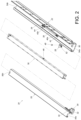
FIG. 2 is an exploded diagram of the slide rail assembly according to the embodiment of the present invention, -
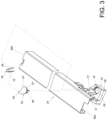
FIG. 3 is a partial exploded diagram of the slide rail assembly according to the embodiment of the present invention, -
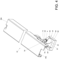
FIG. 4 andFIG. 5 are partial diagrams of the slide rail assembly at different views according to the embodiment of the present invention, -
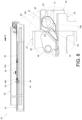
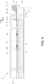
FIG. 6 is a diagram of the slide rail assembly as a second rail is located at a retracted position relative to a first rail according to the embodiment of the present invention, -
FIG. 7 is a diagram of the slide rail assembly as the second rail is pushed from the retracted position relative to the first rail along a first direction according to the embodiment of the present invention, -
FIG. 8 is a diagram of the slide rail assembly as the second rail is driven to displace relative to the first rail along a second direction by a driving device according to the embodiment of the present invention, -
FIG. 9 is a diagram of the slide rail assembly as the second rail is located at an extended position relative to the first rail according to the embodiment of the present invention, and -
FIG. 10 is a diagram of the slide rail assembly as the second rail is pulled from the retracted position relative to the first rail along the second direction according to the embodiment of the present invention. - In the following detailed description of the preferred embodiments, reference is made to the accompanying drawings which form a part hereof, and in which is shown by way of illustration specific embodiments in which the invention may be practiced. In this regard, directional terminology, such as "top", "bottom", "left", "right", "front", "back", etc., is used with reference to the orientation of the Figure(s) being described. The members of the present invention can be positioned in a number of different orientations. As such, the directional terminology is used for purposes of illustration and is in no way limiting. Accordingly, the drawings and descriptions will be regarded as illustrative in nature and not as restrictive. Also, if not specified, the term "connect" is intended to mean either an indirect or direct mechanical connection. Thus, if a first device is connected to a second device, that connection may be through a direct mechanical connection, or through an indirect mechanical connection via other devices and connections.
- As shown in
FIG. 1 andFIG. 2 , aslide rail assembly 20 includes afirst rail 22, asecond rail 24, adriving device 26, a controllingmember 28, an aidingmember 30, a workingmember 32 and aresilient structure 34. - The
second rail 24 is displaceable relative to thefirst rail 22 longitudinally. Preferably, theslide rail assembly 20 can further include athird rail 36 movably mounted between thefirst rail 22 and thesecond rail 24 and for extending a displacement of thesecond rail 24 relative to thefirst rail 22. In practical, thefirst rail 22 can be mounted or fixed on a cabinet, and thesecond rail 24 can be configured to support a drawer. Understandably, in another embodiment, the third rail can be omitted. - As shown in
FIG. 1 , the drivingdevice 26 is configured to drive thesecond rail 24 to be opened after thesecond rail 24 is pushed from a retracted position R relative to thefirst rail 22 along a first direction D1, e.g., a retracting direction. The drivingdevice 26 includes aresilient member 38. In this embodiment, by way of example, theresilient member 38 can be a spring. However, the present invention is not limited to this embodiment. Theresilient member 38 includes afirst end 40a and asecond end 40b opposite to thefirst end 40a. Thefirst end 40a of theresilient member 38 is fixed on thefirst rail 22 by a connectingmember 42. A drivingmember 44 is arranged on thesecond end 40b of theresilient member 38. Preferably, a correspondingmember 46 or a corresponding portion is arranged on thesecond rail 24 or thethird rail 36 and located at a position corresponding to the drivingmember 44, so as to cooperate with the drivingmember 44. In this embodiment, by way of example, the correspondingmember 46 can be arranged on thethird rail 36. However, the present invention is not limited to this embodiment. For example, in another embodiment, the corresponding member or the corresponding portion can be arranged on the second rail. - The controlling
member 28 is movably mounted on one of thefirst rail 22 and thesecond rail 24. In this embodiment, by way of example, the controllingmember 28 can be movably mounted on thefirst rail 22. Specifically, the controllingmember 28 can be pivotally connected to thefirst rail 22 by ashaft 48, such that the controllingmember 28 is pivotable relative to thefirst rail 22. Preferably, as shown inFIG. 6 , thefirst rail 22 includes afirst restraining feature 50, and the controllingmember 28 includes asecond restraining feature 51, wherein one of thefirst restraining feature 50 and thesecond restraining feature 51 is an opening or a recess portion, and the other one of thefirst restraining feature 50 and thesecond restraining feature 51 is an extending leg stretching into the opening or the recess portion and configured to abut against a wall of the opening or the recess portion, such that the controllingmember 28 is only allowed to pivot relative to thefirst rail 22 within a limited range. In this embodiment, by way of example, thefirst restraining feature 50 can be the opening, and thesecond restraining feature 51 can be the extending leg. However, the present invention is not limited to this embodiment. - The controlling
member 28 includes a controllingportion 52. In this embodiment, by way of example, the controllingportion 52 can be a protruding portion or a pin. However, the present invention is not limited to this embodiment. - Preferably, the
first rail 22 includes afront end portion 54a and arear end portion 54b, and the controllingmember 28 is located adjacent to thefront end portion 54a of thefirst rail 22. - As shown in
FIG. 3 ,FIG. 4 andFIG. 5 , the aidingmember 30 is arranged on the other one of thefirst rail 22 and thesecond rail 24 where the controllingmember 28 is not disposed. In this embodiment, by way of example, the aidingmember 30 can be arranged on thesecond rail 24. Preferably, the aidingmember 30 can be connected to thesecond rail 24 directly or indirectly. Thesecond rail 24 includes afront end portion 56a and arear end portion 56b, and the aidingmember 30 is arranged on thesecond rail 24 and located adjacent to thefront end portion 56a of thesecond rail 24. - The working
member 32 is movable relative to the aidingmember 30. In this embodiment, by way of example, the workingmember 32 can be movably mounted on the aidingmember 30. - The
resilient structure 34 is configured to provide a returning resilient force K to the workingmember 32 for resiliently retaining the workingmember 32 in afirst state S 1 as shown inFIG. 4 . In this embodiment, by way of example, theresilient structure 34 can be a leaf spring. However, the present invention is not limited to this embodiment. For example, in another embodiment, the resilient structure can be a spring or any other resiliently deformable object, e.g., a rubber cylinder. - Preferably, the aiding
member 30 is configured to provide a moving space M for the workingmember 32. As shown inFIG. 3 , the moving space M penetrates through afirst portion 58 and asecond portion 60 of the aidingmember 30. - The working
member 32 includes a workingportion 66. Preferably, the workingmember 32 further includes amain body portion 62 and an extendingsection 64. The extendingsection 64 extends from themain body portion 62. The workingportion 66 protrudes from asurface 67 of themain body portion 62. As shown inFIG. 4 , themain body portion 62 and the extendingsection 64 are located adjacent to thefirst portion 58 of the aidingmember 30. As shown inFIG. 5 , the workingportion 66 passes through the moving space M and is located adjacent to thesecond portion 60 of the aidingmember 30. - Preferably, the aiding
member 30 is further configured to provide an aiding receiving space Q for receiving theresilient structure 34. The aiding receiving space Q is located adjacent to the moving space M. Theresilient structure 34 includes a firstpredetermined portion 68 and a secondpredetermined portion 70. As shown inFIG. 3 andFIG. 4 , the firstpredetermined portion 68 is configured to abut against awall 72 of the aidingmember 30, and the secondpredetermined portion 70 is configured to abut against the extendingsection 64 of the workingmember 32. - As shown in
FIG. 5 , the aidingmember 30 includes apredetermined path structure 74, and the workingportion 66 of the workingmember 32 is located adjacent to thepredetermined path structure 74. - Preferably, as shown in
FIG. 5 , the workingportion 66 of the workingmember 32 is a heart-shaped protrusion and surrounded by thepredetermined path structure 74. Thepredetermined path structure 74 includes anentry section 76a and a releasingsection 76b communicated with theentry section 76a. The workingportion 66 of the workingmember 32 is located between theentry section 76a and the releasingsection 76b. - Preferably, the aiding
member 30 further includes a guidingsection 78. In this embodiment, by way of example, the guidingsection 78 can be an inclined surface or an arc surface. The workingportion 66 of the workingmember 32 further includes an abuttingsection 80. - Preferably, as shown in
FIG. 3 orFIG. 5 , thesurface 67 of themain body portion 62 of the workingmember 32, is formed in a substantially circular shape. - As shown in
FIG. 6 , when thesecond rail 24 is located at the retracted position R relative to thefirst rail 22, the controllingmember 28 and the workingportion 66 of the workingmember 32 in the first state S1 can block each other, so as to position the controllingportion 52 of the controllingmember 28 at a locking position L for maintaining a resilient force J provided by theresilient member 38 along a second direction D2, e.g., an opening direction, wherein the second direction D2 is opposite to the first direction D1. - Preferably, when the
second rail 24 is located at the retracted position R relative to thefirst rail 22, the controllingportion 52 of the controllingmember 28 and the abuttingsection 80 of the workingportion 66 of the workingmember 32 in the first state S1 block each other, such that the controllingmember 28 and the workingportion 66 of the workingmember 32 in the first state S1 block each other, so as to position the controllingportion 52 of the controllingmember 28 at the locking position L for maintaining the resilient force J provided by theresilient member 38 along the second direction D2 by a blocking of the controllingportion 52 of the controllingmember 28 and the abuttingsection 80 of the workingportion 66 of the workingmember 32. Furthermore, a locking space X is defined between the guidingsection 78 and the abuttingsection 80 and configured to receive the controllingportion 52 of the controllingmember 28. - Preferably, an offset angle A is formed between an extending line passing through the abutting
section 80 and acenter 82 of the workingmember 32, e.g., a center of themain body portion 62 of the workingmember 32, and an extending line passing through thecenter 82 of the workingmember 32 along the first direction D1 or the second direction D2. - As shown in
FIG. 7 ,FIG. 8 andFIG. 9 , when thesecond rail 24 is pushed by a first force F1 from the retracted position R relative to thefirst rail 22 along the first direction D1, the aidingmember 30 guides the controllingportion 52 of the controllingmember 28 to move from the locking position L relative to thepredetermined path structure 74, so as to allow theresilient member 38 to drive thesecond rail 24 to be opened relative to thefirst rail 22 along the second direction D2 by the resilient force J, e.g., until thesecond rail 24 is displaced to an extended position E. In other words, theslide rail assembly 20 is configured to provide a push-open mechanism which enables thesecond rail 24 to be opened relative to thefirst rail 22 along the second direction D2 by pushing thesecond rail 24 from the retracted position R along thefirst direction D 1. - Preferably, as shown in
FIG. 7 , when thesecond rail 24 is pushed by the first force F1 from the retracted position R relative to thefirst rail 22 along the first direction D1, the controllingportion 52 of the controllingmember 28 and the guidingsection 78 of the aidingmember 30 abut against each other, such that the controllingportion 52 of the controllingmember 28 is guided to move from the locking position L into the releasingsection 76b of thepredetermined path structure 74 by the guidingsection 78, so as to allow theresilient member 38 to drive thesecond rail 24 to be opened along the second direction D2. For example, as shown inFIG. 8 andFIG. 9 , thesecond end 40b of theresilient member 38 can push the correspondingmember 46 on thethird rail 36 by the drivingmember 44 to drive thethird rail 36 and thesecond rail 24 to be opened along the second direction D2. - Preferably, the aiding
member 30 further includes a guidingfeature 84. In this embodiment, by way of example, the guidingfeature 84 can be an inclined surface or an arc surface. As shown inFIG. 8 andFIG. 9 , during a displacement of thesecond rail 24 along the second direction D2 in response to the resilient force J provided by theresilient member 38, the aidingmember 30 drives the controllingportion 52 of the controllingmember 28 to move out of thepredetermined path structure 74 to a position corresponding to theentry section 76a of the aidingmember 30 as shown inFIG. 8 andFIG. 9 by an abutment of the guidingfeature 84 and the controllingportion 52 of the controllingmember 28. Therefore, during a displacement of thesecond rail 24 from the extended position E to the retracted position R along the first direction D1, the controllingportion 52 of the controllingmember 28 can return back to the locking position L as shown inFIG. 6 by entering into thepredetermined path structure 74 through theentry section 76a. - As shown in
FIG. 6 andFIG. 10 , when thesecond rail 24 is pulled by a second force F2 from the retracted position R relative to thefirst rail 22 along the second direction D2, the controllingportion 52 of the controllingmember 28 and the workingportion 66 of the workingmember 32 can abut against each other to generate an acting force V for driving the workingmember 32 to rotate from the first state S1 to a second state S2 as shown inFIG. 10 , such that the controllingportion 52 of the controllingmember 28 is moved from the locking position L relative to thepredetermined path structure 74 for allowing thesecond rail 24 to be opened along the second direction D2. - Preferably, when the
second rail 24 is pulled by the second force F2 from the retracted position R relative to thefirst rail 22 along the second direction D2, the controllingportion 52 of the controllingmember 28 and the workingportion 66 of the workingmember 32 can abut against each other to generate the acting force V for driving the workingmember 32 to rotate from thefirst state S 1 as shown inFIG. 6 to the second state S2 as shown inFIG. 10 easily due to the offset angle A, such that the controllingportion 52 of the controllingmember 28 can be driven by the workingportion 66 of the workingmember 32 to move from the locking position L relative to thepredetermined path structure 74 for allowing thesecond rail 24 to be opened along the second direction D2 easily. Besides, the workingportion 66 of the workingmember 32 further includes a guidingsurface 55 located adjacent to the abuttingsection 80. The controllingportion 52 of the controllingmember 28 includes a guidingcontour 59. In this embodiment, by way of example, the guidingsurface 55 can be an inclined surface or an arc surface, and the guidingcontour 59 can be formed in a circular shape or an arc shape. When thesecond rail 24 is pulled by the second force F2 from the retracted position R relative to thefirst rail 22 along the second direction D2, the controllingportion 52 of the controllingmember 28 and the workingportion 66 of the workingmember 32 can abut against each other to generate the acting force V by a cooperation of the guidingsurface 55 and the guidingcontour 59, which facilitates not only a rotating movement of the workingmember 32 from the first state S1 as shown inFIG. 6 to the second state S2 as shown inFIG. 10 but also a movement of the controllingportion 52 of the controllingmember 28 from the locking position L into the releasingportion 76b of thepredetermined path structure 74. - Furthermore, as shown in
FIG. 10 , when the workingmember 32 is in the second state S2, theresilient structure 34 is resiliently deformed. Therefore, once thesecond rail 24 is displaced from the retracted position R to a predetermined position, e.g., the extended position E, relative to thefirst rail 22 along the second direction D2, the workingmember 32 can return to the first state S1 as shown inFIG. 9 from the second state S2 as shown inFIG. 10 in response to the returning resilient force K provided by theresilient structure 34. - From the above, when the
second rail 24 is located at the retracted position R relative to thefirst rail 22, thesecond rail 24 can be opened normally, i.e., by pushing thesecond rail 24 in the first direction D1. However, if thesecond rail 24 is pulled in the second direction D2 inappropriately, the rotating movement of the workingmember 32 relative to the aidingmember 30 from the first state S1 to the second state S2, allows the controllingportion 52 of the controllingmember 28 to move from the locking position L into the releasingsection 76b of thepredetermined path structure 74, which prevents abrasion or damage of the workingportion 66 of the workingmember 32 and/or the controllingportion 52 of the controllingmember 28 due to friction or a collision, so as to achieve a purpose of protection. - In summary, the
slide rail assembly 20 includes the following characteristics. - 1. When the
second rail 24 is pulled by the second force F2 from the retracted position R relative to thefirst rail 22 along the second direction D2, the controllingportion 52 of the controllingmember 28 and the workingportion 66 of the workingmember 32 can abut against each other to generate the acting force V for driving the workingmember 32 to move from the first state S1 to the second state S2, such that the controllingportion 52 of the controllingmember 28 is moved from the locking position L into the releasingsection 76b of thepredetermined path structure 74 for allowing thesecond rail 24 to be opened along the second direction D2. The rotating movement of the workingmember 32 allows the controllingportion 52 of the controllingmember 28 to move from the locking position L, which prevents abrasion or damage of the workingportion 66 of the workingmember 32 and/or the controllingportion 52 of the controllingmember 28 due to friction or collision. - 2. The working
member 32 can return to the first state S1 as shown inFIG. 9 from the second state S2 as shown inFIG. 10 in response to the returning resilient force K provided by theresilient structure 34 once thesecond rail 24 is displaced from the retracted position R to the predetermined position, e.g., the extended position E. - 3. When the
second rail 24 is pulled by the second force F2 from the retracted position R relative to thefirst rail 22 along the second direction D2, the controllingportion 52 of the controllingmember 28 and the workingportion 66 of the workingmember 32 can abut against each other to generate the acting force V for driving the workingmember 32 to rotate from the first state S1 as shown inFIG. 6 to the second state S2 as shown inFIG. 10 easily due to the offset angle A, such that the controllingportion 52 of the controllingmember 28 can be driven by the workingportion 66 of the workingmember 32 to move from the locking position L relative to thepredetermined path structure 74 for allowing thesecond rail 24 to be opened along the second direction D2 easily. - Those skilled in the art will readily observe that numerous modifications and alterations of the device and method may be made while retaining the teachings of the invention. Accordingly, the above disclosure should be construed as limited only by the metes and bounds of the appended claims.
Claims (15)
- A slide rail assembly (20) comprising:a first rail (22); anda second rail (24) displaceable relative to the first rail (22) along a first direction (D1) or a second direction (D2) opposite to the first direction (D1); andcharacterized by:a driving device (26) comprising a resilient member (38) configured to provide a resilient force (J) along the second direction (D2);a controlling member (28) movably mounted on one of the first rail (22) and the second rail (24), the controlling member (28) comprising a controlling portion (52);an aiding member (30) arranged on another one of the first rail (22) and the second rail (24), the aiding member (30) comprising a predetermined path structure (74);a working member (32) movable relative to the aiding member (30), the working member (32) comprising a working portion (66) located adjacent to the predetermined path structure (74); anda resilient structure (34) configured to provide a returning resilient force (K) to the working member (32) for resiliently retaining the working member (32) in a first state (S1);wherein when the second rail (24) is located at a retracted position (R) relative to the first rail (22), the controlling member (28) and the working portion (66) of the working member (32) in the first state (S1) block each other, so as to position the controlling portion (52) of the controlling member (28) at a locking position (L) for maintaining the resilient force (J) provided by the resilient member (38);wherein when the second rail (24) is pulled from the retracted position (R) relative to the first rail (22) along the second direction (D2), the controlling member (28) and the working portion (66) of the working member (32) in the first state (S1) abut against each other to generate an acting force (V) for driving the working member (32) to rotate from the first state (S1) to a second state (S2), such that the controlling portion (52) of the controlling member (28) is moved from the locking position (L) relative to the predetermined path structure (74) for allowing the second rail (24) to be opened along the second direction (D2).
- The slide rail assembly (20) of claim 1, characterized in that the controlling member (28) is pivotally connected to the first rail (22) by a shaft (48).
- The slide rail assembly (20) of any one of claims 1 and 2, further characterized by a third rail (36) movably mounted between the first rail (22) and the second rail (24), and the third rail (36) being configured to extend a displacement of the second rail (24) relative to the first rail (22).
- The slide rail assembly (20) of any one of claims 1 to 3, characterized in that the aiding member (30) is arranged on the second rail (24), and the working member (32) is movably mounted on the aiding member (30).
- The slide rail assembly (20) of any one of claims 1 to 4, characterized in that the predetermined path structure (74) comprises an entry section (76a) and a releasing section (76b) communicated with the entry section (76a) , and the working portion (66) of the working member (32) is located between the entry section (76a) and the releasing section (76b).
- The slide rail assembly (20) of claim 5, characterized in that the aiding member (30) further comprises a guiding feature (84), during a displacement of the second rail (24) along the second direction (D2) in response to the resilient force (J) provided by the resilient member (38), the aiding member (30) drives the controlling portion (52) of the controlling member (28) to move out of the predetermined path structure (74) to a position corresponding to the entry section (76a) of the aiding member (30) by an abutment of the guiding feature (84) and the controlling portion (52) of the controlling member (28), and during a displacement of the second rail (24) to the retracted position (R) along the first direction (D1), the controlling portion (52) of the controlling member (28) returns back to the locking position (L) by entering into the predetermined path structure (74) through the entry section (76a).
- The slide rail assembly (20) of any one of claims 1 to 6, characterized in that the aiding member (30) is configured to provide a moving space (M) for the working member (32).
- The slide rail assembly (20) of claim 7, characterized in that the working portion (66) passes through the moving space (M) of the aiding member (30).
- The slide rail assembly (20) of any one of claims 1 to 8, wherein when the second rail (24) is pushed from the retracted position (R) relative to the first rail (22) along the first direction (D1), the aiding member (30) guides the controlling portion (52) of the controlling member (28) to move from the locking position (L) relative to the predetermined path structure (74), so as to allow the resilient member (38) to drive the second rail (24) to be opened along the second direction (D2) by the resilient force (J).
- The slide rail assembly (20) of claim 9, characterized in that the aiding member (30) further comprises a guiding section (78), when the second rail (24) is pushed from the retracted position (R) relative to the first rail (22) along the first direction (D1), the controlling portion (52) of the controlling member (28) is guided to move from the locking position (L) into the releasing section (76b) of the predetermined path structure (74) by the guiding section (78), so as to allow the resilient member (38) to drive the second rail (24) to be opened along the second direction (D2).
- The slide rail assembly (20) of any one of claims 1 to 10, characterized in that the working portion (66) of the working member (32) comprises an abutting section (80), an offset angle (A) is formed between an extending line passing through the abutting section (80) and a center of the working member (32) and an extending line passing through the center of the working member (32) along the first direction (D1) or the second direction (D2), and the controlling portion (52) of the controlling member (28) abuts against the abutting section (80) when the controlling portion (52) of the controlling member (28) is located at the locking position (L).
- The slide rail assembly (20) of claim 11, characterized in that when the second rail (24) is located at the retracted position (R) relative to the first rail (22), the controlling member (28) and the working portion (66) of the working member (32) in the first state (S1) block each other, so as to position the controlling portion (52) of the controlling member (28) at the locking position (L) for maintaining the resilient force (J) provided by the resilient member (38) by a blocking of the controlling portion (52) of the controlling member (28) and the abutting section (80).
- The slide rail assembly (20) of any one of claims 11 and 12, characterized in that when the second rail (24) is pulled from the retracted position (R) relative to the first rail (22) along the second direction (D2), the controlling portion (52) of the controlling member (28) and the working portion (66) of the working member (32) in the first state (S1) abut against each other to generate the acting force (V) for driving the working member (32) to rotate from the first state (S 1) to the second state (S2) due to the offset angle (A), such that the controlling portion 52) of the controlling member (28) is moved from the locking position (L) into the releasing section (76b) of the predetermined path structure (74) for allowing the second rail (24) to be opened along the second direction (D2).
- The slide rail assembly (20) of any one of claims 1 to 13, characterized in that the working member (32) returns to the first state (S1) from the second state (S2) in response to the returning resilient force (K) provided by the resilient structure (34).
- The slide rail assembly (20) of any one of claims 1 to 9, characterized in that the aiding member (30) further comprises a guiding section (78), the working portion (66) further comprises an abutting section (80), and a locking space (X) is defined between the guiding section (78) and the abutting section (80) and configured to receive the controlling portion (52) of the controlling member (28).
Applications Claiming Priority (1)
| Application Number | Priority Date | Filing Date | Title |
|---|---|---|---|
| TW112115890A TWI858682B (en) | 2023-04-26 | 2023-04-26 | Slide rail assembly |
Publications (2)
| Publication Number | Publication Date |
|---|---|
| EP4454514A1 true EP4454514A1 (en) | 2024-10-30 |
| EP4454514B1 EP4454514B1 (en) | 2025-08-27 |
Family
ID=88600253
Family Applications (1)
| Application Number | Title | Priority Date | Filing Date |
|---|---|---|---|
| EP23206628.2A Active EP4454514B1 (en) | 2023-04-26 | 2023-10-30 | Slide rail assembly |
Country Status (4)
| Country | Link |
|---|---|
| US (1) | US12383059B2 (en) |
| EP (1) | EP4454514B1 (en) |
| JP (1) | JP7712038B2 (en) |
| TW (1) | TWI858682B (en) |
Citations (4)
| Publication number | Priority date | Publication date | Assignee | Title |
|---|---|---|---|---|
| JP2008296616A (en) * | 2007-05-29 | 2008-12-11 | Toyota Motor Corp | Heart cam lock device |
| CN102755015B (en) * | 2011-04-29 | 2014-03-05 | 川湖科技股份有限公司 | Abutting structure of closing device |
| US8857868B2 (en) | 2011-06-16 | 2014-10-14 | King Slide Works Co., Ltd. | Engaging mechanism of closing device |
| EP2272400B1 (en) | 2009-07-09 | 2019-02-20 | Paul Hettich GmbH & Co. KG | Locking device and drawer slide |
Family Cites Families (5)
| Publication number | Priority date | Publication date | Assignee | Title |
|---|---|---|---|---|
| MY131063A (en) * | 2002-05-17 | 2007-07-31 | Harn Marketing Sdn Bhd | Guide rails pull-out drawer/equipment |
| US8100487B2 (en) * | 2009-11-27 | 2012-01-24 | King Slide Works Co., Ltd. | Auxiliary positioning device for slide assembly |
| AT511329B1 (en) * | 2011-05-03 | 2012-11-15 | Blum Gmbh Julius | LOCKABLE EJECTION DEVICE WITH OVERLOAD MECHANISM |
| TWI421046B (en) * | 2011-06-09 | 2014-01-01 | King Slide Works Co Ltd | Slide assembly with opening mechanism |
| CN111543801B (en) * | 2020-06-20 | 2024-12-24 | 合肥乐卡智能五金制造有限公司 | A strong pull protection mechanism for a press rebounder and a slide rail press rebounder using the same |
-
2023
- 2023-04-26 TW TW112115890A patent/TWI858682B/en active
- 2023-10-02 US US18/375,991 patent/US12383059B2/en active Active
- 2023-10-30 EP EP23206628.2A patent/EP4454514B1/en active Active
- 2023-12-20 JP JP2023214356A patent/JP7712038B2/en active Active
Patent Citations (4)
| Publication number | Priority date | Publication date | Assignee | Title |
|---|---|---|---|---|
| JP2008296616A (en) * | 2007-05-29 | 2008-12-11 | Toyota Motor Corp | Heart cam lock device |
| EP2272400B1 (en) | 2009-07-09 | 2019-02-20 | Paul Hettich GmbH & Co. KG | Locking device and drawer slide |
| CN102755015B (en) * | 2011-04-29 | 2014-03-05 | 川湖科技股份有限公司 | Abutting structure of closing device |
| US8857868B2 (en) | 2011-06-16 | 2014-10-14 | King Slide Works Co., Ltd. | Engaging mechanism of closing device |
Also Published As
| Publication number | Publication date |
|---|---|
| US20240360870A1 (en) | 2024-10-31 |
| TWI858682B (en) | 2024-10-11 |
| JP7712038B2 (en) | 2025-07-23 |
| US12383059B2 (en) | 2025-08-12 |
| JP2024159453A (en) | 2024-11-08 |
| TW202443042A (en) | 2024-11-01 |
| EP4454514B1 (en) | 2025-08-27 |
Similar Documents
| Publication | Publication Date | Title |
|---|---|---|
| TWI704889B (en) | Slide rail assembly | |
| EP3750446B1 (en) | Slide rail assembly | |
| US5207781A (en) | Closing device for moving a drawer to a fully inserted position within a furniture body | |
| EP3387950B1 (en) | Slide rail assembly | |
| TWI706752B (en) | Slide rail assembly | |
| US7708357B2 (en) | Automatic locking apparatus used in guide rail for drawer | |
| KR101593321B1 (en) | Lock structure | |
| TW202119976A (en) | Slide rail assembly | |
| EP0955844A1 (en) | Shock absorbing locking disconnect latch for ball bearing slides | |
| CN114109160A (en) | Vehicle door handle assembly | |
| EP4023108B1 (en) | Slide rail assembly | |
| US10501974B2 (en) | Fitting arrangement for connecting a slidable and tiltable leaf | |
| US20190226233A1 (en) | Noise-reducing strike box | |
| EP2532272B1 (en) | Opening mechanism of slide assembly | |
| EP4454514B1 (en) | Slide rail assembly | |
| EP3387951B1 (en) | Clutch system for furniture parts | |
| EP4461160B1 (en) | Furniture assembly | |
| CN118892254B (en) | slide rail assembly | |
| CN112754197B (en) | Slide rail assembly | |
| EP2371241A1 (en) | Slide assmebly with an opening device | |
| CN112971407A (en) | Sliding rail assembly | |
| US20260009267A1 (en) | Flush Handle Assembly | |
| CN113768302A (en) | Opening and/or closing device for furniture | |
| CN119453679B (en) | slide rail assembly | |
| CN112901656B (en) | Sliding rail assembly |
Legal Events
| Date | Code | Title | Description |
|---|---|---|---|
| PUAI | Public reference made under article 153(3) epc to a published international application that has entered the european phase |
Free format text: ORIGINAL CODE: 0009012 |
|
| STAA | Information on the status of an ep patent application or granted ep patent |
Free format text: STATUS: THE APPLICATION HAS BEEN PUBLISHED |
|
| STAA | Information on the status of an ep patent application or granted ep patent |
Free format text: STATUS: REQUEST FOR EXAMINATION WAS MADE |
|
| AK | Designated contracting states |
Kind code of ref document: A1 Designated state(s): AL AT BE BG CH CY CZ DE DK EE ES FI FR GB GR HR HU IE IS IT LI LT LU LV MC ME MK MT NL NO PL PT RO RS SE SI SK SM TR |
|
| 17P | Request for examination filed |
Effective date: 20241024 |
|
| RBV | Designated contracting states (corrected) |
Designated state(s): AL AT BE BG CH CY CZ DE DK EE ES FI FR GB GR HR HU IE IS IT LI LT LU LV MC ME MK MT NL NO PL PT RO RS SE SI SK SM TR |
|
| GRAP | Despatch of communication of intention to grant a patent |
Free format text: ORIGINAL CODE: EPIDOSNIGR1 |
|
| STAA | Information on the status of an ep patent application or granted ep patent |
Free format text: STATUS: GRANT OF PATENT IS INTENDED |
|
| INTG | Intention to grant announced |
Effective date: 20250425 |
|
| GRAS | Grant fee paid |
Free format text: ORIGINAL CODE: EPIDOSNIGR3 |
|
| GRAA | (expected) grant |
Free format text: ORIGINAL CODE: 0009210 |
|
| STAA | Information on the status of an ep patent application or granted ep patent |
Free format text: STATUS: THE PATENT HAS BEEN GRANTED |
|
| AK | Designated contracting states |
Kind code of ref document: B1 Designated state(s): AL AT BE BG CH CY CZ DE DK EE ES FI FR GB GR HR HU IE IS IT LI LT LU LV MC ME MK MT NL NO PL PT RO RS SE SI SK SM TR |
|
| REG | Reference to a national code |
Ref country code: CH Ref legal event code: EP |
|
| REG | Reference to a national code |
Ref country code: DE Ref legal event code: R096 Ref document number: 602023006092 Country of ref document: DE |
|
| REG | Reference to a national code |
Ref country code: IE Ref legal event code: FG4D |
|
| REG | Reference to a national code |
Ref country code: NL Ref legal event code: MP Effective date: 20250827 |
|
| PG25 | Lapsed in a contracting state [announced via postgrant information from national office to epo] |
Ref country code: IS Free format text: LAPSE BECAUSE OF FAILURE TO SUBMIT A TRANSLATION OF THE DESCRIPTION OR TO PAY THE FEE WITHIN THE PRESCRIBED TIME-LIMIT Effective date: 20251227 |
|
| PGFP | Annual fee paid to national office [announced via postgrant information from national office to epo] |
Ref country code: DE Payment date: 20250826 Year of fee payment: 3 |
|
| PG25 | Lapsed in a contracting state [announced via postgrant information from national office to epo] |
Ref country code: NO Free format text: LAPSE BECAUSE OF FAILURE TO SUBMIT A TRANSLATION OF THE DESCRIPTION OR TO PAY THE FEE WITHIN THE PRESCRIBED TIME-LIMIT Effective date: 20251127 |
|
| REG | Reference to a national code |
Ref country code: LT Ref legal event code: MG9D |
|
| PG25 | Lapsed in a contracting state [announced via postgrant information from national office to epo] |
Ref country code: PT Free format text: LAPSE BECAUSE OF FAILURE TO SUBMIT A TRANSLATION OF THE DESCRIPTION OR TO PAY THE FEE WITHIN THE PRESCRIBED TIME-LIMIT Effective date: 20251229 |
|
| PG25 | Lapsed in a contracting state [announced via postgrant information from national office to epo] |
Ref country code: FI Free format text: LAPSE BECAUSE OF FAILURE TO SUBMIT A TRANSLATION OF THE DESCRIPTION OR TO PAY THE FEE WITHIN THE PRESCRIBED TIME-LIMIT Effective date: 20250827 |
|
| PG25 | Lapsed in a contracting state [announced via postgrant information from national office to epo] |
Ref country code: HR Free format text: LAPSE BECAUSE OF FAILURE TO SUBMIT A TRANSLATION OF THE DESCRIPTION OR TO PAY THE FEE WITHIN THE PRESCRIBED TIME-LIMIT Effective date: 20250827 Ref country code: NL Free format text: LAPSE BECAUSE OF FAILURE TO SUBMIT A TRANSLATION OF THE DESCRIPTION OR TO PAY THE FEE WITHIN THE PRESCRIBED TIME-LIMIT Effective date: 20250827 |
|
| PG25 | Lapsed in a contracting state [announced via postgrant information from national office to epo] |
Ref country code: GR Free format text: LAPSE BECAUSE OF FAILURE TO SUBMIT A TRANSLATION OF THE DESCRIPTION OR TO PAY THE FEE WITHIN THE PRESCRIBED TIME-LIMIT Effective date: 20251128 |
|
| PG25 | Lapsed in a contracting state [announced via postgrant information from national office to epo] |
Ref country code: SE Free format text: LAPSE BECAUSE OF FAILURE TO SUBMIT A TRANSLATION OF THE DESCRIPTION OR TO PAY THE FEE WITHIN THE PRESCRIBED TIME-LIMIT Effective date: 20250827 |
|
| PGFP | Annual fee paid to national office [announced via postgrant information from national office to epo] |
Ref country code: IE Payment date: 20251021 Year of fee payment: 3 |
|
| PG25 | Lapsed in a contracting state [announced via postgrant information from national office to epo] |
Ref country code: LV Free format text: LAPSE BECAUSE OF FAILURE TO SUBMIT A TRANSLATION OF THE DESCRIPTION OR TO PAY THE FEE WITHIN THE PRESCRIBED TIME-LIMIT Effective date: 20250827 |
|
| PG25 | Lapsed in a contracting state [announced via postgrant information from national office to epo] |
Ref country code: BG Free format text: LAPSE BECAUSE OF FAILURE TO SUBMIT A TRANSLATION OF THE DESCRIPTION OR TO PAY THE FEE WITHIN THE PRESCRIBED TIME-LIMIT Effective date: 20250827 Ref country code: PL Free format text: LAPSE BECAUSE OF FAILURE TO SUBMIT A TRANSLATION OF THE DESCRIPTION OR TO PAY THE FEE WITHIN THE PRESCRIBED TIME-LIMIT Effective date: 20250827 |
|
| PG25 | Lapsed in a contracting state [announced via postgrant information from national office to epo] |
Ref country code: RS Free format text: LAPSE BECAUSE OF FAILURE TO SUBMIT A TRANSLATION OF THE DESCRIPTION OR TO PAY THE FEE WITHIN THE PRESCRIBED TIME-LIMIT Effective date: 20251127 |
|
| PG25 | Lapsed in a contracting state [announced via postgrant information from national office to epo] |
Ref country code: ES Free format text: LAPSE BECAUSE OF FAILURE TO SUBMIT A TRANSLATION OF THE DESCRIPTION OR TO PAY THE FEE WITHIN THE PRESCRIBED TIME-LIMIT Effective date: 20250827 |
|
| REG | Reference to a national code |
Ref country code: AT Ref legal event code: MK05 Ref document number: 1828946 Country of ref document: AT Kind code of ref document: T Effective date: 20250827 |
|
| PG25 | Lapsed in a contracting state [announced via postgrant information from national office to epo] |
Ref country code: RO Free format text: LAPSE BECAUSE OF FAILURE TO SUBMIT A TRANSLATION OF THE DESCRIPTION OR TO PAY THE FEE WITHIN THE PRESCRIBED TIME-LIMIT Effective date: 20250827 |
|
| PG25 | Lapsed in a contracting state [announced via postgrant information from national office to epo] |
Ref country code: SM Free format text: LAPSE BECAUSE OF FAILURE TO SUBMIT A TRANSLATION OF THE DESCRIPTION OR TO PAY THE FEE WITHIN THE PRESCRIBED TIME-LIMIT Effective date: 20250827 |
|
| PG25 | Lapsed in a contracting state [announced via postgrant information from national office to epo] |
Ref country code: DK Free format text: LAPSE BECAUSE OF FAILURE TO SUBMIT A TRANSLATION OF THE DESCRIPTION OR TO PAY THE FEE WITHIN THE PRESCRIBED TIME-LIMIT Effective date: 20250827 |
|
| PG25 | Lapsed in a contracting state [announced via postgrant information from national office to epo] |
Ref country code: AT Free format text: LAPSE BECAUSE OF FAILURE TO SUBMIT A TRANSLATION OF THE DESCRIPTION OR TO PAY THE FEE WITHIN THE PRESCRIBED TIME-LIMIT Effective date: 20250827 |
|
| PG25 | Lapsed in a contracting state [announced via postgrant information from national office to epo] |
Ref country code: IT Free format text: LAPSE BECAUSE OF FAILURE TO SUBMIT A TRANSLATION OF THE DESCRIPTION OR TO PAY THE FEE WITHIN THE PRESCRIBED TIME-LIMIT Effective date: 20250827 |
|
| PG25 | Lapsed in a contracting state [announced via postgrant information from national office to epo] |
Ref country code: CZ Free format text: LAPSE BECAUSE OF FAILURE TO SUBMIT A TRANSLATION OF THE DESCRIPTION OR TO PAY THE FEE WITHIN THE PRESCRIBED TIME-LIMIT Effective date: 20250827 |
|
| PG25 | Lapsed in a contracting state [announced via postgrant information from national office to epo] |
Ref country code: SK Free format text: LAPSE BECAUSE OF FAILURE TO SUBMIT A TRANSLATION OF THE DESCRIPTION OR TO PAY THE FEE WITHIN THE PRESCRIBED TIME-LIMIT Effective date: 20250827 Ref country code: EE Free format text: LAPSE BECAUSE OF FAILURE TO SUBMIT A TRANSLATION OF THE DESCRIPTION OR TO PAY THE FEE WITHIN THE PRESCRIBED TIME-LIMIT Effective date: 20250827 |