EP4451517A1 - Stator core and manufacturing method - Google Patents
Stator core and manufacturing method Download PDFInfo
- Publication number
- EP4451517A1 EP4451517A1 EP22907492.7A EP22907492A EP4451517A1 EP 4451517 A1 EP4451517 A1 EP 4451517A1 EP 22907492 A EP22907492 A EP 22907492A EP 4451517 A1 EP4451517 A1 EP 4451517A1
- Authority
- EP
- European Patent Office
- Prior art keywords
- projected
- stator
- diametrally
- fitted
- laminating direction
- Prior art date
- Legal status (The legal status is an assumption and is not a legal conclusion. Google has not performed a legal analysis and makes no representation as to the accuracy of the status listed.)
- Granted
Links
Images



Classifications
-
- H—ELECTRICITY
- H02—GENERATION; CONVERSION OR DISTRIBUTION OF ELECTRIC POWER
- H02K—DYNAMO-ELECTRIC MACHINES
- H02K15/00—Processes or apparatus specially adapted for manufacturing, assembling, maintaining or repairing of dynamo-electric machines
- H02K15/02—Processes or apparatus specially adapted for manufacturing, assembling, maintaining or repairing of dynamo-electric machines of stator or rotor bodies
-
- H—ELECTRICITY
- H02—GENERATION; CONVERSION OR DISTRIBUTION OF ELECTRIC POWER
- H02K—DYNAMO-ELECTRIC MACHINES
- H02K1/00—Details of the magnetic circuit
- H02K1/06—Details of the magnetic circuit characterised by the shape, form or construction
- H02K1/12—Stationary parts of the magnetic circuit
- H02K1/14—Stator cores with salient poles
- H02K1/146—Stator cores with salient poles consisting of a generally annular yoke with salient poles
- H02K1/148—Sectional cores
-
- H—ELECTRICITY
- H02—GENERATION; CONVERSION OR DISTRIBUTION OF ELECTRIC POWER
- H02K—DYNAMO-ELECTRIC MACHINES
- H02K1/00—Details of the magnetic circuit
- H02K1/06—Details of the magnetic circuit characterised by the shape, form or construction
- H02K1/12—Stationary parts of the magnetic circuit
- H02K1/18—Means for mounting or fastening magnetic stationary parts on to, or to, the stator structures
-
- H—ELECTRICITY
- H02—GENERATION; CONVERSION OR DISTRIBUTION OF ELECTRIC POWER
- H02K—DYNAMO-ELECTRIC MACHINES
- H02K15/00—Processes or apparatus specially adapted for manufacturing, assembling, maintaining or repairing of dynamo-electric machines
- H02K15/02—Processes or apparatus specially adapted for manufacturing, assembling, maintaining or repairing of dynamo-electric machines of stator or rotor bodies
- H02K15/021—Magnetic cores
- H02K15/022—Magnetic cores with salient poles
-
- Y—GENERAL TAGGING OF NEW TECHNOLOGICAL DEVELOPMENTS; GENERAL TAGGING OF CROSS-SECTIONAL TECHNOLOGIES SPANNING OVER SEVERAL SECTIONS OF THE IPC; TECHNICAL SUBJECTS COVERED BY FORMER USPC CROSS-REFERENCE ART COLLECTIONS [XRACs] AND DIGESTS
- Y02—TECHNOLOGIES OR APPLICATIONS FOR MITIGATION OR ADAPTATION AGAINST CLIMATE CHANGE
- Y02T—CLIMATE CHANGE MITIGATION TECHNOLOGIES RELATED TO TRANSPORTATION
- Y02T10/00—Road transport of goods or passengers
- Y02T10/60—Other road transportation technologies with climate change mitigation effect
- Y02T10/64—Electric machine technologies in electromobility
Definitions
- the present invention relates to a stator core for an electric motor and the like and a manufacturing method.
- stator core there is one composed of a plurality of laminated stator plates as disclosed in Patent document 1.
- the plurality of the stator plates are fixed together through calking and fixing portions and are welded through welded portions overlapping the fastening and fixing portions.
- the calking and fixing portions and the welded portions causing iron loss overlap each other to suppress the iron loss of the stator core.
- the calking and fixing portions and the welded portions are, however, provided within a yoke. Accordingly, residual stress caused by the calking and shrinkage action caused by the welding are directly affected to the yoke and there is a limit on suppressing the iron loss even if the calking and fixing portions and the welded portions are overlapped.
- a problem to be solved is that there is a limit on suppressing iron loss.
- the present invention provides a stator core in which stator pieces each having teeth segments on an inner periphery of an annular yoke segment are laminated, the stator core comprising a diametrally recessed portion on an outer edge of the stator piece, a diametrally projected segment portion provided in the diametrally recessed portion, a depressed portion and a projected portion in a laminating direction provided respectively on a top face and a bottom face of the diametrally projected segment portion, a fitted portion in which the depressed portion and the projected portion in the laminating direction are fitted by fastening between the stator pieces, and a welded portion welding the depressed portions and the projected portions of the fitted portion in the laminating direction.
- the present invention provides a manufacturing method of the stator core comprising forming the stator piece having the diametrally recessed portion, the diametrally projected segment portion, and the depressed portion and the projected portion in the laminating direction, laminating a plurality of the stator pieces to form the fitted portions with fastening, and welding the laminated stator pieces in the laminating direction to form the welded portion.
- the stator core according to the present invention suppresses an influence range of iron loss caused by the fitted portion and the welded portion from entering into the yoke relative to an outer peripheral face of the stator core as much as possible.
- the manufacturing method of a stator core according to the present invention easily and surely obtains the stator core that suppresses an influence area of iron loss caused by the fitted portion and the welded portion from entering into the yoke relative to an outer peripheral face of the stator core as much as possible.
- the object of improving in suppressing iron loss is achieved by a stator core and a manufacturing method thereof welding a depressed portion and a projected portion between stator pieces on diametrally projected segment portions formed in diametrally recessed portions on outer edges of the stator pieces.
- stator pieces 17 each having teeth segments 21 on an inner periphery of an annular yoke segment 20 are laminated as illustrated in FIGs. 1-7 .
- Each stator piece 17 is provided with a diametrally recessed portion 23, a diametrally projected segment portion 25, and a depressed portion 27 and a projected portion 29 in a laminating direction, and an interface between the stator pieces 17 is provided with a fitted portion 47 and a welded portion 5.
- the recessed portion 23 is provided on an outer edge 35 of each stator piece 17.
- the projected segment portion 25 is provided in the diametrally recessed portion 23.
- the depressed portion 27 and the projected portion 29 are provided respectively on a top face and a bottom face of the diametrally projected segment portion 25.
- the fitted portion 47 is a portion in which the depressed portion 27 and the projected portion 29 in the laminating direction are fitted by fastening between the stator pieces 17.
- the welded portion 5 welds the depressed portion 27 and the projected portion 29 of the fitted portions 47 in the laminating direction.
- the depressed portion 27 and the projected portion 29 in the laminating direction should form the fitted portion 47 between the diametrally projected segment portions 25 in the laminating direction, shapes of which are freely implemented.
- the depressed portion 27 and the projected portion 29 in the laminating direction may be provided on the diametrally projected segment portion 25 in a half-blanking shape.
- the stator core 1 may be provided with a second stator piece 19, a second recessed portion 41, a second projected segment portion 43, an opening portion 39, and a second fitted portion 49.
- the second stator piece 19 is laminated on the stator piece 17 at least at an end in the laminating direction.
- the second diametrally recessed portion 41 is provided on an outer edge of the second stator piece 19, the second diametrally recessed portion 41 is provided.
- the second diametrally projected segment portion 43 is provided in the second diametrally projected segment portion 43 is provided.
- the second projected segment portion 43 has the opening portion 39 having a diametrally recessed shape to which the projected portion 29 in the laminating direction is fitted.
- the second fitted portion 49 the projected portion 29 in the laminated direction is fitted to the opening portion 39 by fastening.
- the welded portion 5 is reached to a peripheral edge of the opening portion 39 and the projected portion 29 of the second fitted portion 49.
- the depressed portion 27 and the projected portion 29 in the laminating direction may have circumferential widths narrower than of the projected segment portion 25. Further, the depressed portion 27 and the projected portion 29 in the laminating direction may be formed within the projected segment portion 25.
- the welded portion 5 may be formed in the projected segment portions 25, 43.
- a whole of the fitted portions 47 and 49 may be eliminated by the welded portions 5.
- a manufacturing method of manufacturing the stator core 1 forms the stator piece 17 each having the diametrally recessed portion 23 and the diametrally projected segment portion 25 and the depressed portion 27 and the projected portion 29 in the laminating direction first.
- a plurality of the stator pieces 17 are laminated to form the fitted portions 47 with calking.
- the welded portion 5 is formed by welding the laminated stator pieces 17 in the laminating direction.
- a manufacturing method of the stator core may form the second stator piece 19 each having the opening portion 39 having a diametrally recessed shape as well as the stator piece 17 having the diametrally recessed portion 23 and the diametrally projected segment portion 25 and the depressed portion 27 and the projected portion 29 in the laminating direction.
- a plurality of the stator pieces 17 are laminated, the second stator piece 19 is laminated on at least at the end in the laminating direction, and the fitted portions 47 and the second fitted portion 49 are formed by fastening.
- the welded portion 5 is formed by welding the laminated stator pieces 17 and the laminated second stator piece 19 in the laminating direction.
- the forming of the stator piece 17 may, after punching contours of the diametrally recessed portion 23 and the diametrally projected segment portion 25 by pressing, form the depressed portion 27 and the projected portion 29 in the laminating direction by pressing, and punch the outer edge 35 of the stator piece 17 by pressing.
- FIG. 1 is a plan view of a stator core according to an embodiment of the present invention.
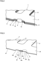
- FIG. 2 is a perspective view illustrating a II-part of FIG. 1 with enlargement.
- FIG. 3 is a perspective view of a stator piece corresponding to the II-part of FIG. 1 .
- FIG. 4 is a perspective view of a second stator piece corresponding to the II-part of FIG. 1 .
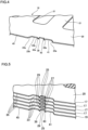
- FIG. 5 is a perspective view illustrating a state before laminating the stator pieces corresponding to the II-part of FIG. 1 .
- FIG. 6 is a perspective view illustrating a laminated state of the stator pieces corresponding to the II-part of FIG. 1 .
- a stator core 1 forms an electromagnet by winding coils (not illustrated) thereto.
- the stator core 1 is configured by laminating a plurality of stator pieces 17 and connecting the stator pieces 17 together by welded portions 5.
- the stator core 1 is provided with the welded portions 5 on an outer peripheral face 3 substantially circular, and is provided on an inner periphery of a yoke 7 with teeth 9 projecting in a diametral direction for winding the coils.
- the diametral direction is a direction along a diameter of the stator core 1.
- a laminating direction is a thickness direction or an axial direction of the stator core 1, and a circumferential direction is a direction along an outer periphery of the stator core 1.
- the welded portion 5 is formed by welding in the laminating direction at fitted portions 47 and a second fitted portion 49 (see FIG. 6 ) to be explained later.
- the welded portion 5 is continuous in the laminating direction and may be formed so as to be spaced in the laminating direction.
- the welded portion 5 is provided over the fitted portions 47 and the second fitted portion 49 entirely in the laminating direction, the circumferential direction and the diametral direction.
- the welded portion 5 may be, however, formed on only part of the fitted portions 47 and the second fitted portion 49 in the laminating direction, the circumferential direction and the diametral direction.
- the fitted portions 47 and the second fitted portion 49 of FIG. 6 are completely eliminated as a result of forming the welded portion 5. Namely, the recessed portions 27 and the projected portions 29 and the opening portion 31 to be explained later in the laminating direction are also eliminated.
- the welded portion 5 may be, however, formed so as to remain these.
- the recessed portions 27, the projected portions 29 and the opening portion 31 as the fitted portions 47 and the second fitted portion 49 should be provided in the premise of the forming of the welded portion 5 and may include a form to be partially or entirely eliminated or partly remained by the welded portion 5.
- the welded portion 5 is provided within a recessed groove portion 11 having a diametrally recessed shape and provided on the circular outer peripheral face 3 of the stator core 1.
- a surface position of a diametrally outward bump of the welded portion 5 is located on an inside within the recessed groove portion 11.
- the range of the welded portion 5 slightly extends to the yoke 7 diametrally inwardly located with respect to the projected segment portion 25.
- the recessed groove portion 11 has a circumferential width being greater than of the welded portion 5 in the circumferential direction.
- an outer peripheral face 13 of the stator core 1 in the recessed groove portion 11 is located on both sides of the welded portion 5 in the circumferential direction.
- the outer peripheral face 13 circumferentially extends to continue to the circular outer peripheral face 3 on an outermost periphery through inclined faces 15 on both sides in the circumferential direction.
- the inclined faces 15 are formed so as to be apart from each other in the circumferential direction toward the diametral outside.
- the stator piece 17 is an annular iron core piece having teeth pieces 21 on an inner periphery of an annular yoke piece 20.
- diametrally recessed portions 23 and diametrally projected segment portions 25 are provided on an outer periphery of the yoke piece 20.
- the yoke piece 20 is laminated with respect to yoke pieces 20 of other stator pieces 17 to form the yoke 7.
- the teeth pieces 21 are laminated with respect to teeth pieces 21 of the other stator pieces 17 to form the teeth 9.
- the diametrally recessed portions 23 and the diametrally projected segment portions 25 are provided on the diametral outside of the yoke piece 20 so as to correspond to the teeth pieces 21.
- These recessed portion 23, the projected segment portion 25, and the depressed portion 27 and the projected portion 29 in the laminated direction are arranged at every some teeth pieces 21 in the circumferential direction. In the present embodiment, the arrangement is performed on totally twelve positions every 30 degrees in a central angle.
- the diametrally recessed portions 23 are formed into a recessed shape inward in the diametral direction with respect to an outer edge 35 of the stator piece 17.
- the outer edge 35 forms the circular outer peripheral face 3 of the stator core 1 after laminating the stator pieces 17.
- the recessed portions 23 form the recessed groove portions 11 of the stator core 1 after laminating the stator pieces 17.
- first inclined edges 23a are formed, the first inclined edges forming inclined faces 15 of the stator core 1 after laminating the stator pieces 17.
- a bottom portion 23b of the recessed shape of the recessed portion 23 forms the outer peripheral face 13 at the recessed groove portion 11 after the laminating.
- the bottom portion 23b is formed by a liner edge or an arc edge continuous to the first inclined edges 23a in the circumferential direction.
- the projected segment portion 25 is provided in the diametrally recessed portion 23.
- the projected segment portion 25 is arranged at a circumferential center of the recessed portion 23 and projected diametrally outwardly from an outer edge 23b of the recessed portion 23.
- a tip end edge 25a of the projected segment portion 25 is formed by a liner edge or an arc edge and is located in the recessed portion 23 in the diametral direction.
- the projected segment portion 25 may be arranged close to any one of the first inclined edges 23a in the circumferential direction. Further, a diametral position of the tip end edge 25a of the projected segment portion 25 may be equivalent to a diametral position of the outer edge 35 of the stator piece 17.
- the projected segment portion 25 and the first inclined edges 23a of the recessed portion 23 are apart from each other with intervals.
- the intervals are, therefore, provided on both sides of the projected segment portion 25 in the circumferential direction.
- a circumferential width of the projected segment portion 25 is narrower than a circumferential width of the recessed portion 23 and about one-third thereof in the present embodiment.
- Second inclined edges 25b are formed on both circumferential side portions of the projected segment portion 25. The second inclined edges 25b are formed so as to taper the projected segment portion 25 toward the diametral outside.
- circumferential width of the projected segment portion 25 may be closer to the circumferential width of the recessed portion 23, and the projected segment portion 25 and the first inclined edges 23a of the recessed portion 23 may be separated with cuts having almost no gap.
- a depressed portion 27 and a projected portion 29 in the laminating direction are respectively provided on a top and a bottom of the projected segment portion 25, a depressed portion 27 and a projected portion 29 in the laminating direction are respectively provided.
- the depressed portion 27 and the projected portion 29 are fitted to each other between the laminated stator pieces 17 by fastening. Namely, the depressed portion 27 of one stator piece 17 is fitted to the projected portion 27 of the other stator piece 17 by fastening between the laminated stator pieces 17.
- the depressed portion 27 and the projected portion 29 of the present embodiment are provided on the projected segment portion 25 in a half-blanking shape.
- the half-blanking shape of the depressed portion 27 and the projected portion 29 in the laminating direction may be implemented by half-blanking process according to pressing.
- a depth of the half-blanking is about 50% of the plate thickness.
- the depth of the half-blanking is, however, not limited thereto.
- the half-blanking does not, therefore, mean to blank by a half of the plate thickness.
- depressed portion 27 and the projected portion 29 should be fitted by fastening between the laminated stator pieces 17 and are processed into a rectangular shape in a plan view, for example.
- a pair of slits in the circumferential direction may be formed on the projected segment portion 25 and the depressed portion and the projected portion may be formed into a cantilevered shape by bending a portion between the slits in the laminating direction.
- the depressed portion 27 and the projected portion 29 of the present embodiment are formed so as to reach the tip end edge 25a of the projected segment portion 25 on the diametral outside. Further, the depressed portion 27 and the projected portion 29 on the diametral inside are formed so as to slightly enter into the yoke piece 20 located on a diametral inside relative to the outer edge 23b in the recessed portion 23 around a root of the projected segment portion 25.
- the diametral insides of the depressed portion 27 and the projected portion 29 may be, however, set at a diametral position identical with the outer edge 23b in the recessed portion 23 or a diametral outer position relative to the outer edge 23b in the recessed portion 23.
- Circumferential widths of the depressed portion 27 and the projected portion 29 are set narrower than the circumferential width of the tip end edge 25a.
- a second stator piece 19 before laminating is formed into the approximately same shape as the stator piece 17 excepting the opening portions 39.
- the second stator piece 19 is provided with teeth pieces 21, second diametrally recessed portions 41, second diametrally projected segment portions 43, and the opening portions 39 with respect to a yoke piece 20.
- the yoke piece 20 and the teeth pieces 21 are the same as of the stator piece 17.
- the second recessed portions 41 are provided on the outer edge 45 of the second stator piece 19, and correspond to the diametrally recessed portions 23 of the stator piece 17.
- the second projected segment portion 43 is provided in the second diametrally recessed portion 41 and is a component corresponding to the radially projected segment portion 25, and the second projected segment portion has the opening portion 39 in place of the depressed portion 27 and the projected portion 29.
- the opening portion 39 is provided so as to correspond to the depressed portion 27 in shape, size, and position.
- the opening portion 39 is formed into a diametrally recessed shape and is open at a tip end edge 43a of the second projected segment portion 43 in the plan view.
- the projected portion 29 in the laminating direction of the stator piece 17 is fitted to the opening portion 39 by fastening.
- a recessed portion may be formed not to pass through the second stator piece 19.
- stator piece 17 in the second stator piece 19 are represented by the same reference numerals to eliminate duplicate explanation.
- a vertical relation in the laminating direction is set for the stator pieces 17 and the second stator piece 19.
- the second stator piece 19 is arranged at an end of the plurality of the stator piece 17 overlappingly arranged in the laminating direction.
- the second stator piece 19 may be arranged between the laminated stator pieces 17.
- the depressed portion 27 and the projected portion 29 are fitted to each other by fastening (calking) between the stator pieces 17, to form the fitted portions 47 between the stator pieces 17.
- the fastening is to act fastening force in the laminating direction such that the depressed portion 27 and the projected portion 29 are matched with each other so as to be fitted.
- the projected portion 29 of the stator piece 17 in the laminating direction is fitted to the opening portion 39 of the second stator piece 19 by fastening between the stator piece 17 and the second stator piece 19, to form the second fitted portion 49 between the stator piece 17 and the second stator piece 19.
- the welded portion 5 in FIG. 2 welds the depressed portion 27 and the projected portion 29 in the laminating direction at the fitted portion 47 illustrated in FIG. 6 .
- the welded portion 5 of the present embodiment reaches the second fitted portion 49.
- the fitted portions 47 and the second fitted portion 49 are melted by the welded portion 5 to form a configuration of FIG. 2 .
- the welded portion 5 melts the depressed portions 27 and the projected portions 29 of the fitted portions 47 in the laminating direction and melts the periphery of the opening portion 39 and the projected portion 29 of the second fitted portion 49 between the stator pieces 17 and 19.
- a manufacturing method of the stator core according to the present embodiment is provided with an iron-core-forming step, a laminating step, and a welding step.
- stator pieces 17 and the second stator piece 19 are formed by press working.
- the press working for the stator piece 17 is provided with a 1st step to a 5th step.
- the 1st step punches a contour of an inner periphery of the stator piece 17 by a 1st pressing.
- the 2nd step punches contours of the teeth pieces 21.
- the 3rd step punches contours of the diametrally recessed portions 23 and the diametrally projected segment portions 25.
- the 4th step forms the depressed portions 27 and the projected portions 29 in the laminating direction by the half-blanking process according to pressing.
- the 5th step punches the outer periphery to form the outer edge 35 to punch the stator piece 17 out.
- the present embodiment forms the depressed portions 27 and the projected portions 29 in the laminating direction by the pressing after punching the contours of the diametrally recessed portions 23 the diametrally projected segment portion 25 by the pressing, and punches the outer edge 35 of the stator piece 17.
- the iron-core-forming step may conduct a single step for the 1st to the 5th steps. Further, the 1st step and the 2nd step may be conducted by a single step and the 3rd to the 5th steps may be conducted subsequently.
- the pressing process is conducted in that order, thereby easily forming the projected segment portion 25 having the depressed portion 27 and the projected portion 29, in particular the projected segment portion 25 having the depressed portion 27 and the projected portion 29 up to the outer periphery (the tip end of the projected segment portion 25 in the diametral direction).
- the pressing process for the second stator piece 19 punches an inner periphery by pressing of the 1st step and punches contours of teeth pieces 21 by the 2nd step similarly to the above.
- the 3rd step punches the second recessed portions 41 and the second projected segment portions 43, and contours of the opening portions 39. Thereafter, the 4th step punches the stator piece 17 out. It should be noted that the opening portion 39 may be punched out by pressing as a different step to the second projected segment portion 43 afterwards.
- the laminating step laminates the plurality of the stator pieces 17 and laminates the second stator piece 19 at the end portion in the laminating direction as illustrated in FIG. 5 and FIG. 6 .
- the depressed portion 27 and the projected portion 29 are fitted to each other by fastening between the projected segment portions 25.
- the projected portion 29 and the opening portion 39 are fitted to each other by fastening between the projected segment portion 25 and the second projected segment portion 43.
- stator pieces 17 and the second stator piece 19 are fixed, to form a stator-piece lamination as illustrated in FIG. 6 .
- stator pieces 17 and the second stator piece 19 are temporarily fixed in the laminated state. This eliminates or suppresses positional deviation between the stator pieces 17 and positional deviation between the stator piece 17 and the second stator piece 19.
- stator pieces 17 and the second stator piece 19 temporarily fixed in the laminated state are pressurized using upper and lower jigs while being positioned, to eliminate gaps between adjacent stator pieces 17 in the laminating direction and between the stator piece 17 and the second stator piece 19 or reduce the gaps to a given level or less.
- the welded portions 5 are formed on the stator pieces 17 and the second stator piece 19 in the laminating direction.
- the welded portions 5 are formed by conducting laser welding or the like to the fitted portions 47 and the second fitted portion 49.
- the depressed portion 27 and the projected portion 29 of each fitted portion 47 are welded, and the projected portion 29 and the periphery of the opening portion 39 of the second fitted portion 49 are welded, and the welded portions 5 are formed.
- the projected segment portions 25 and the second projected segment portions 43 including the fitted portions 47 and the second fitted portion 49 are almost eliminated by melting at the time of the welding, and the welded portion 5 is formed so as to be swelled relatively to the outer peripheral face 13 in the recessed groove portion 11 as illustrated in FIG. 2 .
- the present embodiment forms the welded portion 5 at the fitted portions 47 and the second fitted portion 49 of the projected segment portions 25 and the second projected segment portion 43, so that residual stress caused by the forming and the fastening of the depressed portions 27 and the projected portion 29 is eliminated or reduced to suppress iron loss.
- the depressed portions 27 and the projected portions 29 and the opening portions 39 are eliminated by the welding at the fitted portions 47 and the second fitted portion 49, and tensile stress does not act on the welded portion 5 due to reaction force based on shrinkage in the laminating direction at the time of solidifying to prevent the welded portion 5 from being damaged.
- an influence range of iron loss caused by the fitted portions 47, the second fitted portion 49 and the welded portion 5 is suppressed to be entered into the yoke 7 relative to the outer peripheral face 3 of the stator core 1 to the utmost in the diametral direction.
- intervals are present on the both sides of the projected segment portion 25 and the second projected segment portion 43 in the circumferential direction, so that it suppresses influence of heat caused by the welded portion 5 in the circumferential direction and influence of the heat to part of the yoke 7 adjacent to the intervals in the diametral direction.
- the present embodiment suppresses the influence of the iron loss caused by the fitted portions 47, the second fitted portion 49 and the welded portion 5.
- the welded portion 5 are formed on the projected segment portions 25 and the second projected segment portions 43, thereby promoting the melting to surely perform the welding between the stator piece 17 and the second stator piece 19.
- the welded portion 5 incorporates the projected segment portions 25 to reduce use of welding material. In a case that the whole projected segment portions 25 are incorporated into the welded portion 5 so that the projected segment portions 25 are not in original form or the like, it ensures strong connection rigidity.
- the present embodiment eliminates or suppresses the gaps between the laminated according to shrinkage action at the time of the bead solidifying of the welded portion 5.
- connection rigidity is high between the laminated of the stator core 1 and deformation is eliminated or suppressed when the stator core is installed into a housing. Additionally, it eliminates or suppresses varnish penetration at the time of varnish immersion, and it makes improvements on deformation of the stator core 1.
- the fitted portions 47 and the second fitted portion 49 due to the calking according to the present embodiment are provided to temporarily retain the posture of the stator core lamination. Accordingly, the present embodiment does not need strict accuracy management of a calking tool unlike a conventional calked lamination retaining a posture and a strength with only calking. It, therefore, prolongs a maintenance cycle of a tool and improves productivity.
- the welded portion 5 is located in the recessed groove portion 11. Accordingly, connecting force due to the welded portion 5 in the laminating direction acts on the yoke 7 on the outer peripheral face 13 on the diametral inside relative to the outer peripheral face 3 of the stator core 1.
- connection rigidity therefore, is strongly kept between the laminated at the yoke 7 of the stator core 1.
- the welded portion 5 is also close to the outer peripheral face 3 of the stator core 1, so that the connection rigidity is also surely ensured between the outer peripheral faces 3 adjacent in the laminating direction.
- the connecting is performed at the projected segment portions 25 in the diametrally recessed portion 23 and the second projected segment portion 43 in the second diametrally recessed portion 41, so that the connecting force is easily transferred to both the outer peripheral face 13 and the yoke 7.
- the positional deviation is, therefore, eliminated or suppressed between the stator pieces 17 and between the stator piece 17 and the second stator piece 19, and this is maintained after the welding. Accordingly, it improves accuracy of the stator core 1 and raises rigidity thereof.
- the present embodiment appropriately keeps the posture of the stator core 1 and unifies the stator core by the welding the plurality of the stator pieces 17 and the stator piece 19 that is on the laminated end portion through the pressuring and the positioning.
- the depressed portion 27 and the projected portion 29 are formed narrower than the circumferential width of the projected segment portion 25, and the opening portion 39 is formed narrower than the circumferential width of the second projected segment portion 43. Accordingly, heat is hard to escape from both sides of the depressed portion 27 and the projected portion 29 in the circumferential direction and both sides of the opening portion 39 in the circumferential direction at the time of the forming of the welded portion 5, to improve workability.
- FIG. 7 is a plan view conceptually illustrating part of the stator piece for indicating a welding range of a projected segment portion with enlargement according to a modified example 1 of the embodiment. It should be noted that the basic components are the same as of the above embodiment and the same or corresponding components are represented with the same reference numerals to eliminate duplicate explanation in the modified example 1.
- the diametral positions of the depressed portion 27 and the projected portion 29 relative to the projected segment portion 25 of the stator piece 17 are outer positions relative to the yoke piece 20, and a body portion 26 of the projected segment portion 25 is shaped to be remained between the yoke piece 20 and the depressed portion 27 and the projected portion 29 and on both sides of the depressed portion 27 and the projected portion 29 in the circumferential direction.
- the modified example 1 employs the second stator piece 19 like the second stator piece 19 that is not directly illustrated and numerals doubly represented to the corresponding components with parentheses in FIG. 7 .
- the second stator piece 19 is shaped so that a body portion 26 of the second projected segment portion 43 is remained between the opening portion 39 and the yoke piece 20 and on both sides of the opening portion 39 in the circumferential direction similar to the stator piece 17.
- a welding range W1 includes a whole of the projected segment portions 25 and the second projected segment portion 43 and enters into the yoke piece 20.
- first inclined edges 23a, and the second inclined edges 25b are indicated with no inclination, they may be inclined similarly to the above embodiment.
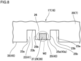
- FIG. 8 is a plan view conceptually illustrating part of a stator piece for indicating a welding range of a projected segment portion with enlargement according to a modified example 2 of the embodiment. It should be noted that the basic components are the same as of the above embodiment and the same or corresponding components are represented with the same reference numerals to eliminate duplicate explanation in the modified example 2.
- the modified example 2 makes the range of the depressed portion 27 and the projected portion 29 relative to the projected segment portion 25 of the stator piece 17 and the range of the opening portion 39 relative to the second projected segment portion 43 be the same as of the modified example 1.
- the second stator piece 19 is the same as of the modified example 1.
- the modified example 2 makes a welding range W2 be within the projected segment portion 25 and the second projected segment portion 43.
- heat is, therefore, further hard to escape in the welding between the depressed portion 27 and the projected portion 29 and the welding between the projected portion 29 and the periphery of the opening portion 39, and it further suppresses influence of the heat relative to the yoke 7 based on the lamination of the yoke pieces 20.
- first inclined edges 23a, and the second inclined edges 25b are indicated with no inclination, they may be inclined.
- FIGs. 9 are a modified example 3 of the present embodiment, in which FIG. 9(A) is a plan view conceptually illustrating part of a stator core piece with enlargement for indicating a range of a depressed portion and a projected portion of a projected segment portion and FIG. 9(B) is a plan view illustrating the stator core piece with enlargement for additionally indicating a welding range.
- FIG. 9(A) is a plan view conceptually illustrating part of a stator core piece with enlargement for indicating a range of a depressed portion and a projected portion of a projected segment portion
- FIG. 9(B) is a plan view illustrating the stator core piece with enlargement for additionally indicating a welding range.
- the basic components are the same as of the above embodiment and the same or corresponding components are represented with the same reference numerals to eliminate duplicate explanation in the modified example 3.
- the modified example 3 is configured to make the range of the depressed portion 27 and the projected portion 29 relative to the projected segment portion 25 of the stator piece 17 and the range of the opening portion 39 relative to the second projected segment portion 43 entirely extend over the projected segment portion 25 and the second projected segment portion 43 in the circumferential direction based on the modified example 2.
- the second stator piece 19 is employed similarly to the modified example 1.
- a welding range W3 be within the projected segment portion 25 and the second projected segment portion 43 similarly to the modified example 2 in the modified example 3.
- the modified example 3 therefore, suppresses influence of the heat relative to the yoke 7 based on the lamination of the yoke pieces 20 in the welding between the depressed portion 27 and the projected portion 29 and the welding between the projected portion 29 and the periphery of the opening portion 39.
- first inclined edges 23a, and the second inclined edges 25b are indicated with no inclination, they may be inclined.
Landscapes
- Engineering & Computer Science (AREA)
- Power Engineering (AREA)
- Manufacturing & Machinery (AREA)
- Iron Core Of Rotating Electric Machines (AREA)
- Manufacture Of Motors, Generators (AREA)
Abstract
Description
- The present invention relates to a stator core for an electric motor and the like and a manufacturing method.
- As a conventional stator core, there is one composed of a plurality of laminated stator plates as disclosed in
Patent document 1. The plurality of the stator plates are fixed together through calking and fixing portions and are welded through welded portions overlapping the fastening and fixing portions. - With the configuration, the calking and fixing portions and the welded portions causing iron loss overlap each other to suppress the iron loss of the stator core.
- The calking and fixing portions and the welded portions are, however, provided within a yoke. Accordingly, residual stress caused by the calking and shrinkage action caused by the welding are directly affected to the yoke and there is a limit on suppressing the iron loss even if the calking and fixing portions and the welded portions are overlapped.
- PATENT LITERATURE 1:
JP2017-5785A - A problem to be solved is that there is a limit on suppressing iron loss.
- The present invention provides a stator core in which stator pieces each having teeth segments on an inner periphery of an annular yoke segment are laminated, the stator core comprising a diametrally recessed portion on an outer edge of the stator piece, a diametrally projected segment portion provided in the diametrally recessed portion, a depressed portion and a projected portion in a laminating direction provided respectively on a top face and a bottom face of the diametrally projected segment portion, a fitted portion in which the depressed portion and the projected portion in the laminating direction are fitted by fastening between the stator pieces, and a welded portion welding the depressed portions and the projected portions of the fitted portion in the laminating direction.
- Further, the present invention provides a manufacturing method of the stator core comprising forming the stator piece having the diametrally recessed portion, the diametrally projected segment portion, and the depressed portion and the projected portion in the laminating direction, laminating a plurality of the stator pieces to form the fitted portions with fastening, and welding the laminated stator pieces in the laminating direction to form the welded portion.
- The stator core according to the present invention suppresses an influence range of iron loss caused by the fitted portion and the welded portion from entering into the yoke relative to an outer peripheral face of the stator core as much as possible.
- The manufacturing method of a stator core according to the present invention easily and surely obtains the stator core that suppresses an influence area of iron loss caused by the fitted portion and the welded portion from entering into the yoke relative to an outer peripheral face of the stator core as much as possible.
-
- [
FIG. 1] FIG. 1 is a plan view of a stator core according to an embodiment. - [
FIG. 2] FIG. 2 is a perspective view illustrating a II-part ofFIG. 1 with enlargement. - [
FIG. 3] FIG. 3 is a perspective view of a stator piece corresponding to the II-part ofFIG. 1 . - [
FIG. 4] FIG. 4 is a perspective view of a second stator piece corresponding to the II-part ofFIG. 1 . - [
FIG. 5] FIG. 5 is a perspective view illustrating a state before laminating the stator pieces corresponding to the II-part ofFIG. 1 . - [
FIG. 6] FIG. 6 is a perspective view illustrating a laminated state of the stator pieces corresponding to the II-part ofFIG. 1 . - [
FIG. 7] FIG. 7 is a plan view conceptually illustrating part of the stator piece with enlargement for indicating a welding range of a projected segment portion according to a modified example 1 of the embodiment. - [
FIG. 8] FIG. 8 is a plan view conceptually illustrating part of a stator piece with enlargement for indicating a welding range of a projected segment portion according to a modified example 2 of the embodiment. - [
FIG. 9] FIG. 9(A) and FIG. 9(B) are a modified example 3 of the embodiment, in whichFIG. 9(A) is a plan view conceptually illustrating part of a stator core piece with enlargement for indicating a range of a depressed portion and a projected portion of a projected segment portion andFIG. 9(B) is a plan view of the stator core piece for additionally indicating a welding range. - The object of improving in suppressing iron loss is achieved by a stator core and a manufacturing method thereof welding a depressed portion and a projected portion between stator pieces on diametrally projected segment portions formed in diametrally recessed portions on outer edges of the stator pieces.
- Namely, in a
stator core 1,stator pieces 17 each having teeth segments 21 on an inner periphery of anannular yoke segment 20 are laminated as illustrated inFIGs. 1-7 . Eachstator piece 17 is provided with a diametrally recessedportion 23, a diametrally projectedsegment portion 25, and adepressed portion 27 and a projectedportion 29 in a laminating direction, and an interface between thestator pieces 17 is provided with a fittedportion 47 and awelded portion 5. - The
recessed portion 23 is provided on anouter edge 35 of eachstator piece 17. The projectedsegment portion 25 is provided in the diametrallyrecessed portion 23. Thedepressed portion 27 and the projectedportion 29 are provided respectively on a top face and a bottom face of the diametrally projectedsegment portion 25. The fittedportion 47 is a portion in which thedepressed portion 27 and the projectedportion 29 in the laminating direction are fitted by fastening between thestator pieces 17. The weldedportion 5 welds thedepressed portion 27 and the projectedportion 29 of the fittedportions 47 in the laminating direction. - The
depressed portion 27 and the projectedportion 29 in the laminating direction should form the fittedportion 47 between the diametrally projectedsegment portions 25 in the laminating direction, shapes of which are freely implemented. Thedepressed portion 27 and the projectedportion 29 in the laminating direction may be provided on the diametrally projectedsegment portion 25 in a half-blanking shape. - The
stator core 1 may be provided with asecond stator piece 19, a second recessedportion 41, a second projectedsegment portion 43, anopening portion 39, and a second fittedportion 49. Thesecond stator piece 19 is laminated on thestator piece 17 at least at an end in the laminating direction. On an outer edge of thesecond stator piece 19, the second diametrally recessedportion 41 is provided. In the second diametrally recessedportion 41, the second diametrally projectedsegment portion 43 is provided. The second projectedsegment portion 43 has theopening portion 39 having a diametrally recessed shape to which the projectedportion 29 in the laminating direction is fitted. In the second fittedportion 49, the projectedportion 29 in the laminated direction is fitted to theopening portion 39 by fastening. In this case, thewelded portion 5 is reached to a peripheral edge of theopening portion 39 and the projectedportion 29 of the second fittedportion 49. - The
depressed portion 27 and the projectedportion 29 in the laminating direction may have circumferential widths narrower than of the projectedsegment portion 25. Further, thedepressed portion 27 and the projectedportion 29 in the laminating direction may be formed within the projectedsegment portion 25. - The
welded portion 5 may be formed in the projectedsegment portions - A whole of the fitted
portions welded portions 5. - A manufacturing method of manufacturing the
stator core 1 forms thestator piece 17 each having the diametrallyrecessed portion 23 and the diametrally projectedsegment portion 25 and thedepressed portion 27 and the projectedportion 29 in the laminating direction first. Next, a plurality of thestator pieces 17 are laminated to form the fittedportions 47 with calking. Next, thewelded portion 5 is formed by welding the laminatedstator pieces 17 in the laminating direction. - Further, a manufacturing method of the stator core may form the
second stator piece 19 each having theopening portion 39 having a diametrally recessed shape as well as thestator piece 17 having the diametrally recessedportion 23 and the diametrally projectedsegment portion 25 and thedepressed portion 27 and the projectedportion 29 in the laminating direction. In this case, a plurality of thestator pieces 17 are laminated, thesecond stator piece 19 is laminated on at least at the end in the laminating direction, and the fittedportions 47 and the second fittedportion 49 are formed by fastening. Next, thewelded portion 5 is formed by welding the laminatedstator pieces 17 and the laminatedsecond stator piece 19 in the laminating direction. - The forming of the
stator piece 17 may, after punching contours of the diametrally recessedportion 23 and the diametrally projectedsegment portion 25 by pressing, form thedepressed portion 27 and the projectedportion 29 in the laminating direction by pressing, and punch theouter edge 35 of thestator piece 17 by pressing. -
FIG. 1 is a plan view of a stator core according to an embodiment of the present invention.FIG. 2 is a perspective view illustrating a II-part ofFIG. 1 with enlargement.FIG. 3 is a perspective view of a stator piece corresponding to the II-part ofFIG. 1 .FIG. 4 is a perspective view of a second stator piece corresponding to the II-part ofFIG. 1 .FIG. 5 is a perspective view illustrating a state before laminating the stator pieces corresponding to the II-part ofFIG. 1 .FIG. 6 is a perspective view illustrating a laminated state of the stator pieces corresponding to the II-part ofFIG. 1 . - As illustrated in
FIGs. 1 and2 , astator core 1 forms an electromagnet by winding coils (not illustrated) thereto. Thestator core 1 is configured by laminating a plurality ofstator pieces 17 and connecting thestator pieces 17 together by weldedportions 5. Thestator core 1 is provided with the weldedportions 5 on an outerperipheral face 3 substantially circular, and is provided on an inner periphery of ayoke 7 withteeth 9 projecting in a diametral direction for winding the coils. - The diametral direction is a direction along a diameter of the
stator core 1. A laminating direction is a thickness direction or an axial direction of thestator core 1, and a circumferential direction is a direction along an outer periphery of thestator core 1. - The welded
portion 5 is formed by welding in the laminating direction atfitted portions 47 and a second fitted portion 49 (seeFIG. 6 ) to be explained later. The weldedportion 5 is continuous in the laminating direction and may be formed so as to be spaced in the laminating direction. - According to the present embodiment, the welded
portion 5 is provided over the fittedportions 47 and the second fittedportion 49 entirely in the laminating direction, the circumferential direction and the diametral direction. The weldedportion 5 may be, however, formed on only part of the fittedportions 47 and the second fittedportion 49 in the laminating direction, the circumferential direction and the diametral direction. - In the embodiment of
FIG. 2 , the fittedportions 47 and the second fittedportion 49 ofFIG. 6 are completely eliminated as a result of forming the weldedportion 5. Namely, the recessedportions 27 and the projectedportions 29 and the opening portion 31 to be explained later in the laminating direction are also eliminated. The weldedportion 5 may be, however, formed so as to remain these. - Accordingly, in the
stator core 1, the recessedportions 27, the projectedportions 29 and the opening portion 31 as the fittedportions 47 and the second fittedportion 49 should be provided in the premise of the forming of the weldedportion 5 and may include a form to be partially or entirely eliminated or partly remained by the weldedportion 5. - The welded
portion 5 is provided within a recessedgroove portion 11 having a diametrally recessed shape and provided on the circular outerperipheral face 3 of thestator core 1. In particular, a surface position of a diametrally outward bump of the weldedportion 5 is located on an inside within the recessedgroove portion 11. According to the present embodiment, the range of the weldedportion 5 slightly extends to theyoke 7 diametrally inwardly located with respect to the projectedsegment portion 25. - The recessed
groove portion 11 has a circumferential width being greater than of the weldedportion 5 in the circumferential direction. On both sides of the weldedportion 5 in the circumferential direction, an outerperipheral face 13 of thestator core 1 in the recessedgroove portion 11 is located. The outerperipheral face 13 circumferentially extends to continue to the circular outerperipheral face 3 on an outermost periphery through inclined faces 15 on both sides in the circumferential direction. The inclined faces 15 are formed so as to be apart from each other in the circumferential direction toward the diametral outside. - As illustrated in
FIG. 3 , thestator piece 17 is an annular iron core piece havingteeth pieces 21 on an inner periphery of anannular yoke piece 20. On an outer periphery of theyoke piece 20, diametrally recessedportions 23 and diametrally projectedsegment portions 25 are provided. - The
yoke piece 20 is laminated with respect toyoke pieces 20 ofother stator pieces 17 to form theyoke 7. On the inner periphery of theyoke piece 20, a plurality of theteeth pieces 21 projected diametrally inwardly are provided at regular intervals in the circumferential direction. Theteeth pieces 21 are laminated with respect toteeth pieces 21 of theother stator pieces 17 to form theteeth 9. - The diametrally recessed
portions 23 and the diametrally projectedsegment portions 25 are provided on the diametral outside of theyoke piece 20 so as to correspond to theteeth pieces 21. These recessedportion 23, the projectedsegment portion 25, and thedepressed portion 27 and the projectedportion 29 in the laminated direction are arranged at every someteeth pieces 21 in the circumferential direction. In the present embodiment, the arrangement is performed on totally twelve positions every 30 degrees in a central angle. - The diametrally recessed
portions 23 are formed into a recessed shape inward in the diametral direction with respect to anouter edge 35 of thestator piece 17. Theouter edge 35 forms the circular outerperipheral face 3 of thestator core 1 after laminating thestator pieces 17. The recessedportions 23 form the recessedgroove portions 11 of thestator core 1 after laminating thestator pieces 17. - On both sides of the recessed
portion 23 in the circumferential direction, firstinclined edges 23a are formed, the first inclined edges forminginclined faces 15 of thestator core 1 after laminating thestator pieces 17. Abottom portion 23b of the recessed shape of the recessedportion 23 forms the outerperipheral face 13 at the recessedgroove portion 11 after the laminating. Thebottom portion 23b is formed by a liner edge or an arc edge continuous to the firstinclined edges 23a in the circumferential direction. - The projected
segment portion 25 is provided in the diametrally recessedportion 23. The projectedsegment portion 25 is arranged at a circumferential center of the recessedportion 23 and projected diametrally outwardly from anouter edge 23b of the recessedportion 23. Atip end edge 25a of the projectedsegment portion 25 is formed by a liner edge or an arc edge and is located in the recessedportion 23 in the diametral direction. - It should be noted that the projected
segment portion 25 may be arranged close to any one of the firstinclined edges 23a in the circumferential direction. Further, a diametral position of thetip end edge 25a of the projectedsegment portion 25 may be equivalent to a diametral position of theouter edge 35 of thestator piece 17. - In the circumference direction, the projected
segment portion 25 and the firstinclined edges 23a of the recessedportion 23 are apart from each other with intervals. The intervals are, therefore, provided on both sides of the projectedsegment portion 25 in the circumferential direction. - A circumferential width of the projected
segment portion 25 is narrower than a circumferential width of the recessedportion 23 and about one-third thereof in the present embodiment. Secondinclined edges 25b are formed on both circumferential side portions of the projectedsegment portion 25. The secondinclined edges 25b are formed so as to taper the projectedsegment portion 25 toward the diametral outside. - It should be noted that the circumferential width of the projected
segment portion 25 may be closer to the circumferential width of the recessedportion 23, and the projectedsegment portion 25 and the firstinclined edges 23a of the recessedportion 23 may be separated with cuts having almost no gap. - On a top and a bottom of the projected
segment portion 25, adepressed portion 27 and a projectedportion 29 in the laminating direction are respectively provided. Thedepressed portion 27 and the projectedportion 29 are fitted to each other between thelaminated stator pieces 17 by fastening. Namely, thedepressed portion 27 of onestator piece 17 is fitted to the projectedportion 27 of theother stator piece 17 by fastening between thelaminated stator pieces 17. - The
depressed portion 27 and the projectedportion 29 of the present embodiment are provided on the projectedsegment portion 25 in a half-blanking shape. The half-blanking shape of thedepressed portion 27 and the projectedportion 29 in the laminating direction may be implemented by half-blanking process according to pressing. A depth of the half-blanking is about 50% of the plate thickness. The depth of the half-blanking is, however, not limited thereto. The half-blanking does not, therefore, mean to blank by a half of the plate thickness. - These
depressed portion 27 and the projectedportion 29 should be fitted by fastening between thelaminated stator pieces 17 and are processed into a rectangular shape in a plan view, for example. Further, a pair of slits in the circumferential direction may be formed on the projectedsegment portion 25 and the depressed portion and the projected portion may be formed into a cantilevered shape by bending a portion between the slits in the laminating direction. - The
depressed portion 27 and the projectedportion 29 of the present embodiment are formed so as to reach thetip end edge 25a of the projectedsegment portion 25 on the diametral outside. Further, thedepressed portion 27 and the projectedportion 29 on the diametral inside are formed so as to slightly enter into theyoke piece 20 located on a diametral inside relative to theouter edge 23b in the recessedportion 23 around a root of the projectedsegment portion 25. - The diametral insides of the
depressed portion 27 and the projectedportion 29 may be, however, set at a diametral position identical with theouter edge 23b in the recessedportion 23 or a diametral outer position relative to theouter edge 23b in the recessedportion 23. Circumferential widths of thedepressed portion 27 and the projectedportion 29 are set narrower than the circumferential width of thetip end edge 25a. - As illustrated in
FIG. 4 , asecond stator piece 19 before laminating is formed into the approximately same shape as thestator piece 17 excepting the openingportions 39. Namely, thesecond stator piece 19 is provided withteeth pieces 21, second diametrally recessedportions 41, second diametrally projectedsegment portions 43, and the openingportions 39 with respect to ayoke piece 20. - The
yoke piece 20 and theteeth pieces 21 are the same as of thestator piece 17. The second recessedportions 41 are provided on theouter edge 45 of thesecond stator piece 19, and correspond to the diametrally recessedportions 23 of thestator piece 17. - The second projected
segment portion 43 is provided in the second diametrally recessedportion 41 and is a component corresponding to the radially projectedsegment portion 25, and the second projected segment portion has the openingportion 39 in place of thedepressed portion 27 and the projectedportion 29. - The opening
portion 39 is provided so as to correspond to thedepressed portion 27 in shape, size, and position. The openingportion 39 is formed into a diametrally recessed shape and is open at atip end edge 43a of the second projectedsegment portion 43 in the plan view. The projectedportion 29 in the laminating direction of thestator piece 17 is fitted to the openingportion 39 by fastening. In addition, although the openingportion 39 passes through thesecond stator piece 19 in the laminating direction, a recessed portion may be formed not to pass through thesecond stator piece 19. - In addition, the same components as the
stator piece 17 in thesecond stator piece 19 are represented by the same reference numerals to eliminate duplicate explanation. - As illustrated in
FIG. 5 , a vertical relation in the laminating direction is set for thestator pieces 17 and thesecond stator piece 19. Thesecond stator piece 19 is arranged at an end of the plurality of thestator piece 17 overlappingly arranged in the laminating direction. In addition, thesecond stator piece 19 may be arranged between thelaminated stator pieces 17. - According to the present embodiment, the
depressed portion 27 and the projectedportion 29 are fitted to each other by fastening (calking) between thestator pieces 17, to form the fittedportions 47 between thestator pieces 17. The fastening is to act fastening force in the laminating direction such that thedepressed portion 27 and the projectedportion 29 are matched with each other so as to be fitted. - Further, the projected
portion 29 of thestator piece 17 in the laminating direction is fitted to the openingportion 39 of thesecond stator piece 19 by fastening between thestator piece 17 and thesecond stator piece 19, to form the second fittedportion 49 between thestator piece 17 and thesecond stator piece 19. - The welded
portion 5 inFIG. 2 welds thedepressed portion 27 and the projectedportion 29 in the laminating direction at the fittedportion 47 illustrated inFIG. 6 . The weldedportion 5 of the present embodiment reaches the second fittedportion 49. The fittedportions 47 and the second fittedportion 49 are melted by the weldedportion 5 to form a configuration ofFIG. 2 . - As this result, the welded
portion 5 melts thedepressed portions 27 and the projectedportions 29 of the fittedportions 47 in the laminating direction and melts the periphery of the openingportion 39 and the projectedportion 29 of the second fittedportion 49 between thestator pieces - A manufacturing method of the stator core according to the present embodiment is provided with an iron-core-forming step, a laminating step, and a welding step.
- In the iron-core-forming step, the
stator pieces 17 and thesecond stator piece 19 are formed by press working. In the present embodiment, the press working for thestator piece 17 is provided with a 1st step to a 5th step. - The 1st step punches a contour of an inner periphery of the
stator piece 17 by a 1st pressing. The 2nd step punches contours of theteeth pieces 21. - The 3rd step punches contours of the diametrally recessed
portions 23 and the diametrally projectedsegment portions 25. - After that, the 4th step forms the
depressed portions 27 and the projectedportions 29 in the laminating direction by the half-blanking process according to pressing. The 5th step punches the outer periphery to form theouter edge 35 to punch thestator piece 17 out. - In this way, the present embodiment forms the
depressed portions 27 and the projectedportions 29 in the laminating direction by the pressing after punching the contours of the diametrally recessedportions 23 the diametrally projectedsegment portion 25 by the pressing, and punches theouter edge 35 of thestator piece 17. - In addition, the iron-core-forming step may conduct a single step for the 1st to the 5th steps. Further, the 1st step and the 2nd step may be conducted by a single step and the 3rd to the 5th steps may be conducted subsequently.
- The pressing process is conducted in that order, thereby easily forming the projected
segment portion 25 having thedepressed portion 27 and the projectedportion 29, in particular the projectedsegment portion 25 having thedepressed portion 27 and the projectedportion 29 up to the outer periphery (the tip end of the projectedsegment portion 25 in the diametral direction). - The pressing process for the
second stator piece 19 punches an inner periphery by pressing of the 1st step and punches contours ofteeth pieces 21 by the 2nd step similarly to the above. - Then, the 3rd step punches the second recessed
portions 41 and the second projectedsegment portions 43, and contours of the openingportions 39. Thereafter, the 4th step punches thestator piece 17 out. It should be noted that the openingportion 39 may be punched out by pressing as a different step to the second projectedsegment portion 43 afterwards. - The laminating step laminates the plurality of the
stator pieces 17 and laminates thesecond stator piece 19 at the end portion in the laminating direction as illustrated inFIG. 5 andFIG. 6 . In this laminating state, thedepressed portion 27 and the projectedportion 29 are fitted to each other by fastening between the projectedsegment portions 25. The projectedportion 29 and the openingportion 39 are fitted to each other by fastening between the projectedsegment portion 25 and the second projectedsegment portion 43. - With this fitting of the laminated state, the
stator pieces 17 and thesecond stator piece 19 are fixed, to form a stator-piece lamination as illustrated inFIG. 6 . In the stator-piece lamination, thestator pieces 17 and thesecond stator piece 19 are temporarily fixed in the laminated state. This eliminates or suppresses positional deviation between thestator pieces 17 and positional deviation between thestator piece 17 and thesecond stator piece 19. - In the welding step, the
stator pieces 17 and thesecond stator piece 19 temporarily fixed in the laminated state are pressurized using upper and lower jigs while being positioned, to eliminate gaps betweenadjacent stator pieces 17 in the laminating direction and between thestator piece 17 and thesecond stator piece 19 or reduce the gaps to a given level or less. - In this state, the welded
portions 5 are formed on thestator pieces 17 and thesecond stator piece 19 in the laminating direction. The weldedportions 5 are formed by conducting laser welding or the like to the fittedportions 47 and the second fittedportion 49. - As this result, the
depressed portion 27 and the projectedportion 29 of each fittedportion 47 are welded, and the projectedportion 29 and the periphery of the openingportion 39 of the second fittedportion 49 are welded, and the weldedportions 5 are formed. According to the embodiment, the projectedsegment portions 25 and the second projectedsegment portions 43 including the fittedportions 47 and the second fittedportion 49 are almost eliminated by melting at the time of the welding, and the weldedportion 5 is formed so as to be swelled relatively to the outerperipheral face 13 in the recessedgroove portion 11 as illustrated inFIG. 2 . - In this way, the present embodiment forms the welded
portion 5 at the fittedportions 47 and the second fittedportion 49 of the projectedsegment portions 25 and the second projectedsegment portion 43, so that residual stress caused by the forming and the fastening of thedepressed portions 27 and the projectedportion 29 is eliminated or reduced to suppress iron loss. - Further, the
depressed portions 27 and the projectedportions 29 and the openingportions 39 are eliminated by the welding at the fittedportions 47 and the second fittedportion 49, and tensile stress does not act on the weldedportion 5 due to reaction force based on shrinkage in the laminating direction at the time of solidifying to prevent the weldedportion 5 from being damaged. - Additionally, an influence range of iron loss caused by the fitted
portions 47, the second fittedportion 49 and the weldedportion 5 is suppressed to be entered into theyoke 7 relative to the outerperipheral face 3 of thestator core 1 to the utmost in the diametral direction. - Further, the intervals are present on the both sides of the projected
segment portion 25 and the second projectedsegment portion 43 in the circumferential direction, so that it suppresses influence of heat caused by the weldedportion 5 in the circumferential direction and influence of the heat to part of theyoke 7 adjacent to the intervals in the diametral direction. - As a result, the present embodiment suppresses the influence of the iron loss caused by the fitted
portions 47, the second fittedportion 49 and the weldedportion 5. - Further, the welded
portion 5 are formed on the projectedsegment portions 25 and the second projectedsegment portions 43, thereby promoting the melting to surely perform the welding between thestator piece 17 and thesecond stator piece 19. - The welded
portion 5 incorporates the projectedsegment portions 25 to reduce use of welding material. In a case that the whole projectedsegment portions 25 are incorporated into the weldedportion 5 so that the projectedsegment portions 25 are not in original form or the like, it ensures strong connection rigidity. - Further, even if fastening force is low at the fitted
portions 47 and the second fittedportion 49, the present embodiment eliminates or suppresses the gaps between the laminated according to shrinkage action at the time of the bead solidifying of the weldedportion 5. - If the gaps between the laminated are little, the connection rigidity is high between the laminated of the
stator core 1 and deformation is eliminated or suppressed when the stator core is installed into a housing. Additionally, it eliminates or suppresses varnish penetration at the time of varnish immersion, and it makes improvements on deformation of thestator core 1. - Further, the fitted
portions 47 and the second fittedportion 49 due to the calking according to the present embodiment are provided to temporarily retain the posture of the stator core lamination. Accordingly, the present embodiment does not need strict accuracy management of a calking tool unlike a conventional calked lamination retaining a posture and a strength with only calking. It, therefore, prolongs a maintenance cycle of a tool and improves productivity. - The welded
portion 5 is located in the recessedgroove portion 11. Accordingly, connecting force due to the weldedportion 5 in the laminating direction acts on theyoke 7 on the outerperipheral face 13 on the diametral inside relative to the outerperipheral face 3 of thestator core 1. - The connection rigidity, therefore, is strongly kept between the laminated at the
yoke 7 of thestator core 1. The weldedportion 5 is also close to the outerperipheral face 3 of thestator core 1, so that the connection rigidity is also surely ensured between the outer peripheral faces 3 adjacent in the laminating direction. - In the stator core lamination of
FIG. 6 , the connecting is performed at the projectedsegment portions 25 in the diametrally recessedportion 23 and the second projectedsegment portion 43 in the second diametrally recessedportion 41, so that the connecting force is easily transferred to both the outerperipheral face 13 and theyoke 7. - In the
stator core 1, the positional deviation is, therefore, eliminated or suppressed between thestator pieces 17 and between thestator piece 17 and thesecond stator piece 19, and this is maintained after the welding. Accordingly, it improves accuracy of thestator core 1 and raises rigidity thereof. - Further, the present embodiment appropriately keeps the posture of the
stator core 1 and unifies the stator core by the welding the plurality of thestator pieces 17 and thestator piece 19 that is on the laminated end portion through the pressuring and the positioning. - The
depressed portion 27 and the projectedportion 29 are formed narrower than the circumferential width of the projectedsegment portion 25, and the openingportion 39 is formed narrower than the circumferential width of the second projectedsegment portion 43. Accordingly, heat is hard to escape from both sides of thedepressed portion 27 and the projectedportion 29 in the circumferential direction and both sides of the openingportion 39 in the circumferential direction at the time of the forming of the weldedportion 5, to improve workability. -
FIG. 7 is a plan view conceptually illustrating part of the stator piece for indicating a welding range of a projected segment portion with enlargement according to a modified example 1 of the embodiment. It should be noted that the basic components are the same as of the above embodiment and the same or corresponding components are represented with the same reference numerals to eliminate duplicate explanation in the modified example 1. - In the modified example 1 of
FIG. 7 , the diametral positions of thedepressed portion 27 and the projectedportion 29 relative to the projectedsegment portion 25 of thestator piece 17 are outer positions relative to theyoke piece 20, and abody portion 26 of the projectedsegment portion 25 is shaped to be remained between theyoke piece 20 and thedepressed portion 27 and the projectedportion 29 and on both sides of thedepressed portion 27 and the projectedportion 29 in the circumferential direction. - Further, the modified example 1 employs the
second stator piece 19 like thesecond stator piece 19 that is not directly illustrated and numerals doubly represented to the corresponding components with parentheses inFIG. 7 . Thesecond stator piece 19 is shaped so that abody portion 26 of the second projectedsegment portion 43 is remained between the openingportion 39 and theyoke piece 20 and on both sides of the openingportion 39 in the circumferential direction similar to thestator piece 17. - A welding range W1 includes a whole of the projected
segment portions 25 and the second projectedsegment portion 43 and enters into theyoke piece 20. With the presence of thebody portion 26 of the projectedsegment portion 25 surrounding thedepressed portion 27 and the projectedportion 29 and thebody portion 26 of the second projectedportion 43 surrounding theopening portion 3, heat is hard to escape in the welding between thedepressed portion 27 and the projectedportion 29 and the welding between the projectedportion 29 and the periphery of the openingportion 39, and it suppresses influence of the heat relative to theyoke 7 based on the lamination of theyoke pieces 20. - In addition, the modified example provides the same effect as the above.
- In
FIG. 7 , although the firstinclined edges 23a, and the secondinclined edges 25b are indicated with no inclination, they may be inclined similarly to the above embodiment. -
FIG. 8 is a plan view conceptually illustrating part of a stator piece for indicating a welding range of a projected segment portion with enlargement according to a modified example 2 of the embodiment. It should be noted that the basic components are the same as of the above embodiment and the same or corresponding components are represented with the same reference numerals to eliminate duplicate explanation in the modified example 2. - As illustrated in
FIG. 8 , the modified example 2 makes the range of thedepressed portion 27 and the projectedportion 29 relative to the projectedsegment portion 25 of thestator piece 17 and the range of the openingportion 39 relative to the second projectedsegment portion 43 be the same as of the modified example 1. Thesecond stator piece 19 is the same as of the modified example 1. - On the other hand, the modified example 2 makes a welding range W2 be within the projected
segment portion 25 and the second projectedsegment portion 43. - In the modified example 2, heat is, therefore, further hard to escape in the welding between the
depressed portion 27 and the projectedportion 29 and the welding between the projectedportion 29 and the periphery of the openingportion 39, and it further suppresses influence of the heat relative to theyoke 7 based on the lamination of theyoke pieces 20. - In addition, the modified example provides the same effect as the above.
- Even in
FIG. 8 , although the firstinclined edges 23a, and the secondinclined edges 25b are indicated with no inclination, they may be inclined. -
FIGs. 9 are a modified example 3 of the present embodiment, in whichFIG. 9(A) is a plan view conceptually illustrating part of a stator core piece with enlargement for indicating a range of a depressed portion and a projected portion of a projected segment portion andFIG. 9(B) is a plan view illustrating the stator core piece with enlargement for additionally indicating a welding range. It should be noted that the basic components are the same as of the above embodiment and the same or corresponding components are represented with the same reference numerals to eliminate duplicate explanation in the modified example 3. - As illustrated in
FIGs. 9 , the modified example 3 is configured to make the range of thedepressed portion 27 and the projectedportion 29 relative to the projectedsegment portion 25 of thestator piece 17 and the range of the openingportion 39 relative to the second projectedsegment portion 43 entirely extend over the projectedsegment portion 25 and the second projectedsegment portion 43 in the circumferential direction based on the modified example 2. Thesecond stator piece 19 is employed similarly to the modified example 1. - On the other hand, a welding range W3 be within the projected
segment portion 25 and the second projectedsegment portion 43 similarly to the modified example 2 in the modified example 3. - Even the modified example 3, therefore, suppresses influence of the heat relative to the
yoke 7 based on the lamination of theyoke pieces 20 in the welding between thedepressed portion 27 and the projectedportion 29 and the welding between the projectedportion 29 and the periphery of the openingportion 39. - In addition, the modified example provides the same effect as the above.
- Even in
FIG. 9 , although the firstinclined edges 23a, and the secondinclined edges 25b are indicated with no inclination, they may be inclined. -
- 1
- Stator core
- 3
- Circular outer peripheral face
- 5
- Welded portion
- 7
- Yoke
- 9
- Teeth
- 11
- Recessed groove portion
- 13
- Outer peripheral face in recessed groove portion
- 15
- Inclined face
- 17
- Stator piece (Annular iron core piece)
- 19
- Second stator piece (Second annular iron core piece)
- 20
- Annular yoke piece
- 21
- Teeth piece
- 23
- Diametrally recessed portion
- 23a
- Outer edge
- 25
- Diametrally projected segment portion
- 27
- Depressed portion in laminating direction
- 29
- Projected portion in laminating direction
- 35
- Outer edge of stator piece
- 39
- Opening
- 41
- Second recessed portion
- 43
- Second projected segment portion
- 45
- Outer edge
- 47
- Fitted portion
- 49
- Second fitted portion
Claims (11)
- A stator core in which stator pieces each having teeth segments on an inner periphery of an annular yoke segment are laminated, comprising:a diametrally recessed portion on an outer edge of the stator piece;a diametrally projected segment portion provided in the diametrally recessed portion;a depressed portion and a projected portion in a laminating direction provided respectively on a top face and a bottom face of the diametrally projected segment portion;a fitted portion in which the depressed portion and the projected portion in the laminating direction are fitted by fastening between the stator pieces; anda welded portion welding the depressed portion and the projected portion of the fitted portion in the laminating direction.
- The stator core according to claim 1, wherein
the depressed portion and the projected portion in the laminating direction are provided on the diametrally projected segment portion in a half-blanking shape. - The stator core according to claim 1 or 2, further comprising:a second stator piece laminated on the stator piece at least at an end in the laminating direction;a second diametrally recessed portion provided on an outer edge of the second stator piece;a second diametrally projected segment portion provided in the second diametrally recessed portion;an opening portion provided in the second projected segment portion and having a diametrally recessed shape to which the projected portion in the laminating direction;a second fitted portion in which the projected portion in the laminated direction is fitted by fastening to the opening having the recessed shape, whereinthe welded portion is led to a peripheral edge of the opening portion and the projected portion in the laminating direction of the second fitted portion.
- The stator core according to claim 1 or 2, wherein
the depressed portion and the projected portion in the laminating direction have circumferential widths narrower than of the projected segment portion. - The stator core according to claim 1 or 2, wherein
the welded portion is formed in the projected segment portions. - The stator core according to claim 1 or 2, wherein
the depressed portion and the recessed portion in the laminating direction are formed within the projected segment portion. - The stator core according to claim 1 or 2, wherein
a whole of the fitted portion is eliminated by the welded portions. - The stator core according to claim 3, wherein
a whole of the fitted portion and the second fitted portion is eliminated by the welded portions. - A manufacturing method of manufacturing the stator core according to claim 1 or 2, comprising:forming the stator piece having the diametrally recessed portion and the diametrally projected segment portion and the depressed portion and the projected portion in the laminating direction;laminating a plurality of the stator pieces to form the fitted portions with fastening; andwelding the laminated stator pieces in the laminating direction to form the welded portion.
- A manufacturing method of manufacturing the stator core according to claim 3, comprising:forming the stator piece having the diametrally recessed portion and the diametrally projected segment portion and the depressed portion and the projected portion in the laminating direction;forming the second stator piece having the opening portion diametrally recessed;laminating a plurality of the stator pieces, laminating the second stator piece to be arranged on at least the end in the laminating direction, and forming the fitted portions and the second fitted portion by fastening; andwelding the laminated stator pieces and the laminated second stator piece in the laminating direction to form the welded portion.
- The manufacturing method of the stator core according to claim 9, wherein
the forming of the stator piece, after punching contours of the diametrally recessed portion and the diametrally projected segment portion, forms the depressed portion and the projected portion in the laminating direction by pressing, and punches the outer edge of the stator piece.
Applications Claiming Priority (2)
| Application Number | Priority Date | Filing Date | Title |
|---|---|---|---|
| JP2021203169 | 2021-12-15 | ||
| PCT/JP2022/046089 WO2023112969A1 (en) | 2021-12-15 | 2022-12-14 | Stator core and manufacturing method |
Publications (3)
| Publication Number | Publication Date |
|---|---|
| EP4451517A1 true EP4451517A1 (en) | 2024-10-23 |
| EP4451517A4 EP4451517A4 (en) | 2025-06-25 |
| EP4451517B1 EP4451517B1 (en) | 2026-04-22 |
Family
ID=86774331
Family Applications (1)
| Application Number | Title | Priority Date | Filing Date |
|---|---|---|---|
| EP22907492.7A Active EP4451517B1 (en) | 2021-12-15 | 2022-12-14 | Stator core and manufacturing method |
Country Status (4)
| Country | Link |
|---|---|
| EP (1) | EP4451517B1 (en) |
| JP (1) | JP7479579B2 (en) |
| CN (1) | CN118120128A (en) |
| WO (1) | WO2023112969A1 (en) |
Families Citing this family (1)
| Publication number | Priority date | Publication date | Assignee | Title |
|---|---|---|---|---|
| KR20250166661A (en) * | 2024-05-21 | 2025-11-28 | 삼성전자주식회사 | Stator assembly and method for manufacturing the same |
Family Cites Families (4)
| Publication number | Priority date | Publication date | Assignee | Title |
|---|---|---|---|---|
| JP2017005785A (en) * | 2015-06-05 | 2017-01-05 | ダイキン工業株式会社 | Stator, motor, and stator manufacturing method |
| JP6509373B2 (en) * | 2015-12-15 | 2019-05-08 | 三菱電機株式会社 | Core sheet, divided laminated core and stator, and method of manufacturing divided laminated core |
| JP6457969B2 (en) * | 2016-05-19 | 2019-01-23 | 株式会社三井ハイテック | Manufacturing method of laminated iron core |
| JP2020065375A (en) * | 2018-10-17 | 2020-04-23 | 日本電産株式会社 | Stator core and motor |
-
2022
- 2022-12-14 WO PCT/JP2022/046089 patent/WO2023112969A1/en not_active Ceased
- 2022-12-14 JP JP2023567821A patent/JP7479579B2/en active Active
- 2022-12-14 CN CN202280070491.XA patent/CN118120128A/en active Pending
- 2022-12-14 EP EP22907492.7A patent/EP4451517B1/en active Active
Also Published As
| Publication number | Publication date |
|---|---|
| JPWO2023112969A1 (en) | 2023-06-22 |
| WO2023112969A1 (en) | 2023-06-22 |
| JP7479579B2 (en) | 2024-05-08 |
| CN118120128A (en) | 2024-05-31 |
| EP4451517A4 (en) | 2025-06-25 |
| EP4451517B1 (en) | 2026-04-22 |
Similar Documents
| Publication | Publication Date | Title |
|---|---|---|
| US9154005B2 (en) | Rotor core for rotating electrical machine, and manufacturing method thereof | |
| US8916254B2 (en) | Method for manufacturing laminated core and laminated core | |
| KR20140133543A (en) | Turbine generator stator core attachment technique | |
| US20130026878A1 (en) | Stator in an electric motor | |
| EP4451517B1 (en) | Stator core and manufacturing method | |
| US10476339B2 (en) | Armature and method for producing armature | |
| CN106688166B (en) | Manufacturing method of laminated core of vehicle drive motor | |
| CN109546765A (en) | A kind of split-type stator core construction and joining method | |
| CN107959390B (en) | Method for manufacturing laminated iron core and laminated iron core | |
| WO2011047483A1 (en) | Permanent magnet rotor assembly provided with welded magnet retaining elements | |
| US11482912B2 (en) | Manufacturing method of core for rotary electric machine | |
| CN116365738A (en) | rotating electrical machine | |
| CN111279584A (en) | Armature core for rotating electrical machine and method for manufacturing armature core for rotating electrical machine | |
| JP5358517B2 (en) | Manufacturing method of laminated iron core | |
| JP7037348B2 (en) | Iron core manufacturing method | |
| TW201728052A (en) | Core sheet, split laminated core, stator and method for manufacturing split laminated core | |
| JP2017093191A (en) | Laminated iron core and manufacturing method thereof | |
| JP2016146739A (en) | Laminated iron core and method for producing laminated iron core | |
| JP6683459B2 (en) | Method for manufacturing laminated core | |
| EP3582369A1 (en) | Annular core piece and annular core | |
| JP2005118796A (en) | Butt welding method | |
| JP7158241B2 (en) | Laminated core manufacturing method | |
| US10958144B2 (en) | Method of manufacturing an induction rotor | |
| JP2005184925A (en) | Stator manufacturing method, rotating electric machine having stator manufactured by the method, and stator manufacturing apparatus | |
| EP4704308A1 (en) | Method of manufacturing laminated core, laminated core, and motor |
Legal Events
| Date | Code | Title | Description |
|---|---|---|---|
| STAA | Information on the status of an ep patent application or granted ep patent |
Free format text: STATUS: THE INTERNATIONAL PUBLICATION HAS BEEN MADE |
|
| PUAI | Public reference made under article 153(3) epc to a published international application that has entered the european phase |
Free format text: ORIGINAL CODE: 0009012 |
|
| STAA | Information on the status of an ep patent application or granted ep patent |
Free format text: STATUS: REQUEST FOR EXAMINATION WAS MADE |
|
| 17P | Request for examination filed |
Effective date: 20240617 |
|
| AK | Designated contracting states |
Kind code of ref document: A1 Designated state(s): AL AT BE BG CH CY CZ DE DK EE ES FI FR GB GR HR HU IE IS IT LI LT LU LV MC ME MK MT NL NO PL PT RO RS SE SI SK SM TR |
|
| DAV | Request for validation of the european patent (deleted) | ||
| DAX | Request for extension of the european patent (deleted) | ||
| A4 | Supplementary search report drawn up and despatched |
Effective date: 20250523 |
|
| RIC1 | Information provided on ipc code assigned before grant |
Ipc: H02K 15/02 20060101ALI20250519BHEP Ipc: H02K 1/18 20060101AFI20250519BHEP |
|
| GRAP | Despatch of communication of intention to grant a patent |
Free format text: ORIGINAL CODE: EPIDOSNIGR1 |
|
| STAA | Information on the status of an ep patent application or granted ep patent |
Free format text: STATUS: GRANT OF PATENT IS INTENDED |
|
| INTG | Intention to grant announced |
Effective date: 20251219 |
|
| GRAS | Grant fee paid |
Free format text: ORIGINAL CODE: EPIDOSNIGR3 |
|
| GRAA | (expected) grant |
Free format text: ORIGINAL CODE: 0009210 |
|
| STAA | Information on the status of an ep patent application or granted ep patent |
Free format text: STATUS: THE PATENT HAS BEEN GRANTED |
|
| AK | Designated contracting states |
Kind code of ref document: B1 Designated state(s): AL AT BE BG CH CY CZ DE DK EE ES FI FR GB GR HR HU IE IS IT LI LT LU LV MC ME MK MT NL NO PL PT RO RS SE SI SK SM TR |
|
| REG | Reference to a national code |
Ref country code: CH Ref legal event code: F10 Free format text: ST27 STATUS EVENT CODE: U-0-0-F10-F00 (AS PROVIDED BY THE NATIONAL OFFICE) Effective date: 20260422 Ref country code: GB Ref legal event code: FG4D |
|
| REG | Reference to a national code |
Ref country code: DE Ref legal event code: R096 Ref document number: 602022035293 Country of ref document: DE |