EP4451498A1 - Method for load control of an electrolysis plant and electrolysis plant - Google Patents
Method for load control of an electrolysis plant and electrolysis plant Download PDFInfo
- Publication number
- EP4451498A1 EP4451498A1 EP23168412.7A EP23168412A EP4451498A1 EP 4451498 A1 EP4451498 A1 EP 4451498A1 EP 23168412 A EP23168412 A EP 23168412A EP 4451498 A1 EP4451498 A1 EP 4451498A1
- Authority
- EP
- European Patent Office
- Prior art keywords
- electrolysis
- transformer
- module
- plant
- rectifier
- Prior art date
- Legal status (The legal status is an assumption and is not a legal conclusion. Google has not performed a legal analysis and makes no representation as to the accuracy of the status listed.)
- Withdrawn
Links
Images


Classifications
-
- H—ELECTRICITY
- H02—GENERATION; CONVERSION OR DISTRIBUTION OF ELECTRIC POWER
- H02J—ELECTRIC POWER NETWORKS; CIRCUIT ARRANGEMENTS OR SYSTEMS FOR SUPPLYING OR DISTRIBUTING ELECTRIC POWER; SYSTEMS FOR STORING ELECTRIC ENERGY
- H02J3/00—Circuit arrangements for AC mains or AC distribution networks
- H02J3/12—Arrangements for adjusting voltage in AC networks by changing a characteristic of the network load
- H02J3/14—Arrangements for adjusting voltage in AC networks by changing a characteristic of the network load by switching loads on to, or off from, the networks, e.g. progressively balanced loading
-
- C—CHEMISTRY; METALLURGY
- C25—ELECTROLYTIC OR ELECTROPHORETIC PROCESSES; APPARATUS THEREFOR
- C25B—ELECTROLYTIC OR ELECTROPHORETIC PROCESSES FOR THE PRODUCTION OF COMPOUNDS OR NON-METALS; APPARATUS THEREFOR
- C25B1/00—Electrolytic production of inorganic compounds or non-metals
- C25B1/01—Products
- C25B1/02—Hydrogen or oxygen
- C25B1/04—Hydrogen or oxygen by electrolysis of water
-
- C—CHEMISTRY; METALLURGY
- C25—ELECTROLYTIC OR ELECTROPHORETIC PROCESSES; APPARATUS THEREFOR
- C25B—ELECTROLYTIC OR ELECTROPHORETIC PROCESSES FOR THE PRODUCTION OF COMPOUNDS OR NON-METALS; APPARATUS THEREFOR
- C25B15/00—Operating or servicing cells
- C25B15/02—Process control or regulation
-
- H—ELECTRICITY
- H02—GENERATION; CONVERSION OR DISTRIBUTION OF ELECTRIC POWER
- H02J—ELECTRIC POWER NETWORKS; CIRCUIT ARRANGEMENTS OR SYSTEMS FOR SUPPLYING OR DISTRIBUTING ELECTRIC POWER; SYSTEMS FOR STORING ELECTRIC ENERGY
- H02J3/00—Circuit arrangements for AC mains or AC distribution networks
- H02J3/28—Arrangements for balancing of the load in networks by storage of energy
-
- H—ELECTRICITY
- H02—GENERATION; CONVERSION OR DISTRIBUTION OF ELECTRIC POWER
- H02J—ELECTRIC POWER NETWORKS; CIRCUIT ARRANGEMENTS OR SYSTEMS FOR SUPPLYING OR DISTRIBUTING ELECTRIC POWER; SYSTEMS FOR STORING ELECTRIC ENERGY
- H02J2105/00—Networks for supplying or distributing electric power characterised by their spatial reach or by the load
- H02J2105/50—Networks for supplying or distributing electric power characterised by their spatial reach or by the load for selectively controlling the operation of the loads
Definitions
- the invention relates to a method for load control of an electrolysis plant according to the preamble of claim 1 and an electrolysis plant according to the preamble of claim 11.
- Large scale electrolysis plants typically have a modular setup, wherein the plant comprises a number of electrolysis modules, each comprising a stack of individual electrolysis cells, which modules are supplied by an equal number of transformer-rectifier units that are connected to the power grid.
- the electrical power from the distribution or even transmission level of the power grid is typically first transformed and distributed by one or more switchgears carrying an AC switchgear voltage to the transformer-rectifier units.
- the transformer-rectifier units transform the AC switchgear voltage to an AC intermediary voltage and convert this AC intermediary voltage into an individual DC module voltage.
- the transformer-rectifier units are controlled by an electronic control unit in order to change the voltage level of the individual DC module voltages and thereby set the respective module load set point for each electrolysis module. By controlling the module load set points of all modules the total energy demand and/or product output of the plant is controlled.
- US 4,363,101 A describes a computerized power demand control in an electrochemical plant of the above-described type according to the preambles of claims 1 and 11.
- energy is supplied to each electrolytic cell line through an individual tapping transformer controlled by a computer.
- the tapped output of the transformer is fed in a corresponding converter generating direct current for the respective electrolytic cell line.
- Each cell line has an individual power meter and an individual ampere meter feeding back information to the computer.
- Current is controlled by tap regulation under command of the computer in order to achieve toward the end of each demand period, an ideal rate of consumption, whereby the overall plant totalizes energy consumed in such amount to meet the assigned target.
- each cell line or electrolysis module is a separate, independently controlled consumer of electrical energy.
- every AC/DC converter is imperfect to some extent, each of the converters used to supply DC power to the electrolysis cells will give rise to disturbing harmonics of the primary frequency of the AC voltage being superimposed to the DC voltage and - in a back-reaction - also to the power grid.
- electrolysis plants for the electrolysis of water used to produce so-called green hydrogen will be much larger than conventional chlor-alkali plants and will have a nominal power in the range of hundred(s) of megawatts or even in the gigawatt range.
- These large scale plants will have a considerably stronger back-effect on the grid and will need to be able to be operated with significantly stronger fluctuations in the load set point depending on the availability of green energy, which is influenced e.g. by weather conditions (sunshine, wind, etc.).
- the method comprises the following steps that are carried out by the control unit:
- At least two of the electrolysis modules are associated to the transformer-rectifier unit, and the transformer-rectifier unit contains one common transformer and one rectifier per associated electrolysis module.
- the AC intermediary voltages supplied by the common transformer to the associated rectifiers differ by a preset first phase difference, and the optimization step is carried out with the constraint that any two electrolysis modules associated to the same transformer-rectifier unit are to be operated at the same module load set point.
- the method according to the invention is based on the technical insight that interfering harmonic frequencies of the primary frequency of the AC intermediary voltage are generated in all rectifiers of the plant and occur in a fixed phase relation with respect to the AC intermediary voltage leading.
- the parasitic harmonics caused by different rectifiers therefore add up due to constructive interference on the plant level.
- at least two rectifiers arranged within the same transformer-rectifier unit are fed by AC intermediary voltages from a common transformer that differ by a preset first phase difference.
- the preset first phase difference has the effect that there is an at least partial negative interference of the disturbing harmonics already at the level of the transformer-rectifier unit. The amplitude of the resulting disturbing harmonics upstream of the transformer rectifier unit is therefore reduced.
- the method according to the invention allows for a comparatively economical reduction of disturbing harmonics by intelligent plant design and load control. While it is generally possible to reduce harmonics by building ever more complex and thus more ideal rectifiers that directly cause a lower fraction of disturbing harmonics, the method according to the invention acknowledges the fact, that on the DC side there is no need for an ideal DC module voltage, because electrolysis cells are not very sensitive to pulsations, and the back reactions on the AC side can be reduced by combining several rectifiers within a transformer-rectifier unit in a smart way. Thus, the plant can be designed e.g. with comparatively simple 6-pulse rectifiers.
- the electrolysis plant comprises at least one second transformer-rectifier unit, wherein the transformer-rectifier units are connected to a common power supply switchgear, wherein the AC intermediary voltages of the transformer-rectifier units pairwise differ by a preset second phase difference.
- the second phase difference corresponds to the first phase difference divided by the number of transformer-rectifier units attached to the common switchgear.
- the optimization is carried out with the constraint that any two electrolysis modules connected to the same switchgear are to be operated at the same module load set point.
- the term "corresponds to" according to this disclosure means that the second phase difference is equal to the first phase difference divided by the number of transformer-rectifier units attached to the common switchgear up to a tolerance of +/-10 %, or preferably +/-5 %.
- the first phase difference is adapted to be most effective in the cancellation of a particular lower order of harmonics
- the second phase difference being an integer divisor of the first phase difference will be effective in reducing a corresponding higher order of disturbing harmonics.
- the first phase difference corresponds to 60° divided by the number of electrolysis modules being supplied by the same transformer-rectifier unit.
- the term "corresponds to” according to this disclosure means that the first phase difference is equal to 60° divided by the number of electrolysis modules being supplied by the same transformer-rectifier unit up to a tolerance of +/-10 %, or preferably +/-5 %.
- the optimization is carried out with the further constraint that the module load set points are to be chosen from a fixed set of permissible load set points.
- a harmonic filter on the plant level in order to mitigate any remnant disturbing harmonics.
- the design of such a harmonic filter will be more simple and thus more economical, if the module load set points of the electrolysis plant are chosen from a fixed set of permissible load set points, because the structure and intensity of the harmonics occurring at those load set points can be calculated or simulated beforehand.
- the set of permissible load set points is a discrete set.
- the set of permissible load set points includes a shutdown of the respective module corresponding to zero load.
- the method for load control can shut down modules completely to a zero load set point.
- the electrolysis modules are grouped into at least two groups, wherein the optimization is carried out with the constraint that the number of executed shutdowns is evenly distributed among the electrolysis modules of each group. Having at least two groups of electrolysis modules with an almost equal number of performed shutdowns is advantageous with respect to the maintenance schedule of the modules. By having different shutdown groups of modules it is possible to have for example different groups queuing for refurbishment at different points in time. Having an even distribution of shutdowns within each of these group will therefore result in making better use of the permissible number of shutdowns. In a peer group of modules being next in line for refurbishment that have on average a rather low efficiency and rather high number of shutdowns, already, shutdowns are encouraged for comparatively high efficient modules of that group. On the other hand, shutdowns are avoided for comparatively low efficient modules in a peer group of freshly refurbished modules with a low number of shutdowns on average.
- the constraints discussed above are implemented as soft constraints to the plant efficiency function, in such a way that the extent to which the soft constraint is violated is penalized in plant efficiency function.
- the optimization step according to the invention therefore comprises an optimization in the sense of a mathematical algorithm that iteratively finds a locally optimal solution for the plant efficiency function.
- constraints it can be advantageous to implement constraints as so-called soft constraints.
- Soft constraints influence the position of locally optimal solutions within variable space, but do not strictly exclude optimal solutions that (slightly) violate these constraints.
- an electrolysis plant comprising
- control unit is configured to perform the method according to the invention as described above.
- the object is achieved by a computer program comprising instructions which, when the program is executed by a control unit in an electrolysis plant according to the invention, cause the control unit to carry out the inventive method as described above.
- a computer-readable storage medium comprising instructions which, when executed by a control unit in an electrolysis plant according to the invention cause the control unit to carry out the inventive method as described above.
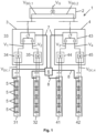
- Fig. 1 shows an exemplary embodiment of an electrolysis plant 1 according to the invention.
- the electrolysis plant comprises, as an example, four electrolysis modules 31, 32, 41, 42.
- Each electrolysis module 31, 32, 41, 42 comprises a plurality of electrolysis cells 5 that are connected electrically in series.
- the cells 5 of each module 31, 32, 41, 42 form a so-called cell stack which is connected to appropriate piping (not shown) for feeding and discharging electrolysis educts and products to/from the stack.
- the electrolysis plant 1 further comprises two transformer-rectifier units 3, 4 for providing the electrolysis modules 31, 32; 41, 42 respectively associated to each of the transformer-rectifier units 3, 4 with an individual DC module voltage V DC,i chosen as to meet a module load set point L i of the respective module 31, 32; 41, 42.
- V DC DC module voltage
- at least two electrolysis modules 31, 32; 41, 42 are associated to each transformer-rectifier unit 3; 4.
- the index i stands here and in the following for the respective module number and thus runs from 1 to 4, in this example.
- the transformer-rectifier units 3, 4 each comprise a common transformer 33; 43 and one rectifier 34, 35; 44, 45 per associated electrolysis module 31, 32; 41, 42.
- the common transformer 33; 43 provides an individual AC intermediary voltage V i to the rectifiers 34, 35; 44, 45 of the transformer-rectifier unit 3, 4 and the rectifiers 34, 35; 44, 45 convert the AC intermediary voltage V i into the respective DC module voltage V DC,i .
- the electrolysis plant comprises a control unit 6 that is connected, e.g. via control lines 7, to the transformer-rectifier units 3, 4 for setting the module load set points L i of the associated electrolysis modules 31, 32; 41, 42.
- the control unit 6 may also be connected to the electrolysis modules 31, 32; 41, 42 via measuring lines 8 to obtain actual values of the current and/or DC module voltage of each of the electrolysis modules 31, 32; 41, 42. Thereby a closed loop control for the module load set point L i can be obtained.
- the transformer-rectifier units 3, 4 are connected to a common power supply switchgear 2.
- the power supply switchgear 2 provides AC switchgear voltages V SG,1 , V SG,2 to the transformer-rectifier units 3, 4.
- the AC switchgear voltages V SG,1 , V SG,2 may be identical, or different from one another e.g. by a phase difference.
- the transformer rectifier units 3, 4 each are configured such that the AC intermediary voltages V i supplied by the common transformer 33; 43 to the associated rectifiers 34, 35; 44, 45 differ by a preset first phase difference D1.
- the first phase difference D1 may preferably be established within the common transformer 33; 43 by having two different types of secondary windings (for example star, delta or zigzag windings).
- Fig. 2 shows in its upper part the AC intermediary voltages V 1 , V 2 occurring within the transformer rectifier unit 3 and in its lower part the AC intermediary voltages V 3 , V 4 occurring within the transformer rectifier unit 4.
- the AC intermediary voltages V 1 , V 2 ; V 3 , V 4 differ by a first phase difference D1, respectively, which is exemplarily chosen at 30°.
- the first phase difference D1 has the preferred value given by 60° divided by the number of electrolysis modules 31, 32; 41, 42 being supplied by the same transformer-rectifier unit 3; 4, which is two.
- the AC intermediary voltages V 1 and V 3 and the AC intermediary voltages V 2 and V 4 pairwise differ by a preset second phase difference D2 of 15°.
- the second phase difference D2 corresponds to the first phase difference D1 divided by the number of transformer-rectifier units 3, 4 attached to the common switchgear 2, which is equal to two.
- Fig. 3A shows schematically an AC grid voltage V G which is heavily disturbed by disturbing harmonics of the 5 th and 7 th order as a back-reaction from rectifiers in a prior art electrolysis plant.
- Fig. 3B shows an AC grid voltage V G with reduced disturbing harmonics due to negative interference on the level of the transformer-rectifier units 3, 4 by means of the first phase difference D1 and equal load distribution of the associated electrolysis modules 31, 32; 41, 42.
- Fig. 3C shows an AC grid voltage V G with further reduced disturbing harmonics due to negative interference on the level of the common switchgear 2 by means of the second phase difference D2 and equal load distribution of the associated electrolysis modules 31, 32, 41, 42.
- the control unit 6 of the electrolysis plant 1 according to Fig. 1 and 2 is preferably configured to perform the method according to the invention, which is explained in more detail with reference to Figs. 4 to 6 in the following.
- Fig 4 shows a flow chart of the method according to the invention.
- the method starts by the step 100 of determining a plant load set point L, P of the electrolysis plant 1 corresponding to a target energy supply and/or target product output of the electrolysis plant 1.
- the subset of operationally ready modules may be determined, being the only modules to be considered during the further steps of the method.
- the module efficiency E i of each of the considered electrolysis modules 31, 32; 41, 42 is determined.
- the optional step 200 may also be included into step 300 e.g. by assigning a specific efficiency value, for example a zero or negative efficiency to any electrolysis module that is currently not ready for operation. Thereby, the non-operational electrolysis modules can be marked and excluded from further consideration.
- the method continues by the step 400 during which a plant efficiency function of the electrolysis plant 1 is optimized.
- the plant efficiency function has the module load set points L i of the electrolysis modules 31, 32; 41, 42 as variables and the module efficiencies E i as given parameters being held fixed during the optimization.
- the optimization step is carried out with the constraint 410 to meet the plant load set point L, P.
- the plant efficiency function thus relates module load set points L i and the module efficiencies E i with the plant load set point L, P.
- the optimization step 400 is further carried out with the constraint 420 that any two electrolysis modules 31, 32; 41, 42 associated to the same transformer-rectifier unit 3; 4 are to be operated at the same module load set point L i , in order to achieve the reduction of disturbing harmonics according to the invention.
- An additional, optional constraint 430 to be taken into account during optimization may be that any two electrolysis modules 31, 32, 41, 42 connected to the same switchgear 2 are to be operated at the same module load set point L i , if the electrolysis plant is configured such that the AC intermediary voltages V i of the transformer-rectifier units 3, 4 pairwise differ by a preset second phase difference D2 with the second phase difference D2 corresponding to the first phase difference D1 divided by the number of transformer-rectifier units 3, 4 attached to the common switchgear 2.
- the optimization step 400 may be carried out with further optional constraints that are discussed in more detail below.
- the method ends by the step 500 in which the module load set points L i of the modules 31, 32; 41, 42 are set according to the optimized plant efficiency function.
- the module load set points L i can be set by the control unit 6 sending corresponding commands to the transformer-rectifier units 3, 4 via control lines 7 (cf. Fig. 1 ).
- step 100 After the method has ended, it may be started again from step 100.
- the start of the method may be triggered at certain time intervals, or event-based, e.g. always when updated data is received from which an updated plant load set point L, P can be determined.
- the optimization step 400 can be subject to several additional, optional constraints: For example, the optimization can be carried out with the constraint that the module load set points L i are to be chosen from a fixed set of permissible load set points.
- electrolysis modules have a minimum permissible load set point below which the module cannot be operated, but has to be shut down, i.e. set to zero load.
- an exemplary set of permissible module load set point may be given by ⁇ 0%, [10%-100%] ⁇ , i.e. the shutdown state 0% and the range of 10% to 100% of the nominal load. It may also be permissible to exceed the nominal 100% load state by 5% or even up to 10% for a limited amount of time.
- a discrete set of permissible load set points e.g. ⁇ 0%, 10%, 25% 50%, 75%, 100% ⁇ . This may be helpful in order to simplify the design of a harmonic filter used to block remnant disturbing harmonics.
- a threshold number of permissible shutdowns per module 31, 32, 41, 42 may be defined, wherein the control unit 6 counts the number of executed shutdowns for each electrolysis module 31, 32, 41, 42.
- the optimization step 400 is the carried out with the constraint 440 that the threshold number of permissible shutdowns must not be exceeded for any electrolysis module 31, 32, 41, 42.
- a maximum permissible duration per shutdown may be defined, wherein the control unit 6 measures the duration of executed shutdowns for each electrolysis module 31, 32, 41, 42.
- the optimization step 400 is then carried out with the constraint 450 that the maximum permissible duration per shutdown must not be exceeded for any electrolysis module 31, 32, 41, 42.
- the electrolysis modules 31, 32, 41, 42 may be grouped into at least two groups, and the optimization step 400 is carried out with the constraint 460 that the number of executed shutdowns is evenly distributed among the electrolysis modules 31, 32, 41, 42 of each group.
- constraints 410, 420, 430, 440, 450, 460 can be implemented as soft constraints to the plant efficiency function. This can, for example, be done in such a way that the extent to which the soft constraint is violated is penalized in the plant efficiency function.
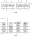
- Fig. 5 and Fig. 6 contain an illustrative numerical example on how the different constraints during optimization step 400 influence the load set points L i of the electrolysis modules and the total efficiency of the electrolysis plant 1. It is to be noted that the module efficiencies E i assumed in this example are purely fictitious and are chosen to rather extreme values in order to highlight the effects of the invention.
- Fig. 5 shows very schematically another embodiment of an electrolysis plant 1 according to the invention.
- the size of the electrolysis plant 1 has been doubled such that it contains eight modules 31, 32, 41, 42, 31', 32', 41', 42', four transformer-rectifier units, 3, 4, 3', 4' and two switchgears 2, 2'.
- Fig. 5 further shows the module efficiencies E i for each module.
- the boxes representing the electrolysis modules in Fig. 5 each have a differently shaded filling, which provides the key for reading the column diagrams of Fig. 6 .
- the first column of Fig. 6 represents a load distribution according to the prior art.
- the 560 units of electrical energy are distributed among the most efficient modules in descending order of efficiency.
- the five most efficient modules 31, 32, 41, 31' and 32' are attributed 100 units of electrical energy and 6 th efficient module 42' is attributed the remaining 60 units of electrical energy.
- the two least efficient modules 42 and 41' are attributed zero load and are switched off.
- the second to fourth columns of Fig. 6 represent several load distributions according to the present invention.
- the second column shows the effect of the constraint 420 being taken into account, namely that the electrolysis modules 31, 32; 41, 42; 31', 32'; 41', 42' supplied by the same transformer-rectifier unit 3; 4; 3'; 4' are to be operated at the same module load set point L i .
- the electrical energy is now allocated to the three pairs of electrolysis modules 31, 32; 41, 42; 31', 32' that have the best efficiency on average. Consequently the - on average - least efficient pair of electrolysis modules 41', 42' is attributed zero load, i.e. is shut down.
- the third column of Fig. 6 shows the effect of the constraint 440 being taken into account in addition to the constraints 410 and 420, i.e. that the total number of shutdowns for every module is limited.
- the threshold number of permissible shutdowns will be reached first for those modules 41', 42'.
- the threshold value of permissible shutdowns has already been reached for the modules 41', 42'. Otherwise, the situation corresponds to that of the second column.
- the modules 41' and 42' cannot be shut down any more, and are therefore operated at the lowest permissible operating load, which is assumed to be 10%, in this example.
- the fourth column of Fig. 6 shows the effect of the constraint 430 being taken into account in addition to the constraints 410 and 420.
- all modules 31, 32, 41, 42; 31', 32', 41', 42' supplied by the same switchgear 2, 2' are to be operated at the same module load set point L i .
- the modules 31, 32, 41, 42 connected to switchgear 2 have an on average higher efficiency and are thus each allocated 100 units of electrical energy.
- the remaining 160 units of electrical energy are evenly distributed among the modules 31', 32', 41', 42' supplied by switchgear 2' that have an on average lower efficiency.
- the optimization step 400 comprises an optimization of the plant efficiency function both with and without constraint 430 and to decide based on the extent of the expected overall efficiency reduction of the plant, whether to set the modules at a load set point respecting constraint 430 in addition to the other constraints, or not.
Landscapes
- Chemical & Material Sciences (AREA)
- Engineering & Computer Science (AREA)
- Power Engineering (AREA)
- Chemical Kinetics & Catalysis (AREA)
- Electrochemistry (AREA)
- Materials Engineering (AREA)
- Metallurgy (AREA)
- Organic Chemistry (AREA)
- Inorganic Chemistry (AREA)
- Automation & Control Theory (AREA)
- Electrolytic Production Of Non-Metals, Compounds, Apparatuses Therefor (AREA)
Abstract
The invention relates to a method for load control of an electrolysis plant comprising the steps of
- determining (100) a plant load set point (L, P) of the electrolysis plant corresponding to a target energy supply and/or target product output of the electrolysis plant,
- determining (300) a module efficiency (Ei) of each electrolysis module,
- optimizing (400) a plant efficiency function of the electrolysis plant having the module load set points (Li) of the electrolysis modules as variables and the module efficiencies (Ei) as parameters with the constraint (410) to meet the plant load set point (L, P),
- setting (500) the module load set points (Li) of the electrolysis modules according to the optimized plant efficiency function,
wherein the optimization step (400) is carried out with the constraint (420) that any two electrolysis modules supplied by the same transformer-rectifier unit with AC intermediary voltages differing by a preset first phase difference before rectification are to be operated at the same module load set point (Li), and an electrolysis plant adapted to carry out the method.
- determining (100) a plant load set point (L, P) of the electrolysis plant corresponding to a target energy supply and/or target product output of the electrolysis plant,
- determining (300) a module efficiency (Ei) of each electrolysis module,
- optimizing (400) a plant efficiency function of the electrolysis plant having the module load set points (Li) of the electrolysis modules as variables and the module efficiencies (Ei) as parameters with the constraint (410) to meet the plant load set point (L, P),
- setting (500) the module load set points (Li) of the electrolysis modules according to the optimized plant efficiency function,
wherein the optimization step (400) is carried out with the constraint (420) that any two electrolysis modules supplied by the same transformer-rectifier unit with AC intermediary voltages differing by a preset first phase difference before rectification are to be operated at the same module load set point (Li), and an electrolysis plant adapted to carry out the method.
Description
- The invention relates to a method for load control of an electrolysis plant according to the preamble of
claim 1 and an electrolysis plant according to the preamble of claim 11. - Large scale electrolysis plants typically have a modular setup, wherein the plant comprises a number of electrolysis modules, each comprising a stack of individual electrolysis cells, which modules are supplied by an equal number of transformer-rectifier units that are connected to the power grid. The electrical power from the distribution or even transmission level of the power grid is typically first transformed and distributed by one or more switchgears carrying an AC switchgear voltage to the transformer-rectifier units. The transformer-rectifier units transform the AC switchgear voltage to an AC intermediary voltage and convert this AC intermediary voltage into an individual DC module voltage. The transformer-rectifier units are controlled by an electronic control unit in order to change the voltage level of the individual DC module voltages and thereby set the respective module load set point for each electrolysis module. By controlling the module load set points of all modules the total energy demand and/or product output of the plant is controlled.
-
US 4,363,101 A describes a computerized power demand control in an electrochemical plant of the above-described type according to the preambles ofclaims 1 and 11. In order to provide regulation of the electrolytic production processes within the cells and at the same time meet the power demand constraints, energy is supplied to each electrolytic cell line through an individual tapping transformer controlled by a computer. The tapped output of the transformer is fed in a corresponding converter generating direct current for the respective electrolytic cell line. Each cell line has an individual power meter and an individual ampere meter feeding back information to the computer. Current is controlled by tap regulation under command of the computer in order to achieve toward the end of each demand period, an ideal rate of consumption, whereby the overall plant totalizes energy consumed in such amount to meet the assigned target. - According to this known setup of power demand control in an electrochemical plant, each cell line or electrolysis module is a separate, independently controlled consumer of electrical energy. As every AC/DC converter is imperfect to some extent, each of the converters used to supply DC power to the electrolysis cells will give rise to disturbing harmonics of the primary frequency of the AC voltage being superimposed to the DC voltage and - in a back-reaction - also to the power grid.
- In the traditional setup of electrochemical plants as e.g. in the chlor-alkali industry these back-reactions to the grid have been restricted to an acceptable level either by the limited size of these plants or by employing a harmonic filter on the level of the switch gear of the plant, filtering out the superimposed harmonics. The design of such a harmonic filter was comparatively simple, because electrochemical plants like chlor-alkali plants typically run almost all of the time very close to their nominal power consumption in order to maximize product output and profit. Thus, the structure and composition of the harmonics produced by the converters was known beforehand and did not change significantly during operation.
- With the rise of renewable energies becoming the main source of electrical power, the power supply and the electricity prices will be subject to larger fluctuations than before. Moreover, electrolysis plants for the electrolysis of water used to produce so-called green hydrogen will be much larger than conventional chlor-alkali plants and will have a nominal power in the range of hundred(s) of megawatts or even in the gigawatt range. These large scale plants will have a considerably stronger back-effect on the grid and will need to be able to be operated with significantly stronger fluctuations in the load set point depending on the availability of green energy, which is influenced e.g. by weather conditions (sunshine, wind, etc.).
- Thus, in present and future electrolysis plants there is a need to be able to control the load of the plant in a more variable way, while at the same time limiting the back-reactions on the grid due to harmonics generation within the plant. In particular, harmonic filters that could be used in principle to reduce the back-reactions on the grid become very expensive and difficult to design in order to meet these requirements under varying load set points.
- It is therefore the object of the present invention, to provide a method for load control of an electrolysis plant and an electrolysis plant by which the back-reaction of the electrolysis plant to the power grid due to disturbing harmonics generated within the electrolysis plant is reduced.
- This object is achieved by the method with the features of
claim 1. - Hereby, a method for load control of an electrolysis plant is provided, wherein the electrolysis plant comprises
- at least two electrolysis modules each comprising a plurality of electrolysis cells (5) that are connected electrically in series,
- at least one transformer-rectifier unit for providing the electrolysis modules associated to the transformer-rectifier unit with an individual DC module voltage to meet a module load set point of the respective module. The transformer-rectifier unit comprises a transformer for providing an AC intermediary voltage and a rectifier for converting the AC intermediary voltage into the respective DC module voltage, and
- a control unit connected to the transformer-rectifier unit for setting the module load set points of the associated electrolysis modules.
- The method comprises the following steps that are carried out by the control unit:
- determining a plant load set point of the electrolysis plant corresponding to a target energy supply and/or target product output of the electrolysis plant,
- determining a module efficiency of each of the electrolysis modules,
- optimizing a plant efficiency function of the electrolysis plant having the module load set points of the electrolysis modules as variables and the module efficiencies as parameters with the constraint to meet the plant load set point, and
- setting the module load set points of the modules according to the optimized plant efficiency function.
- According to the invention at least two of the electrolysis modules are associated to the transformer-rectifier unit, and the transformer-rectifier unit contains one common transformer and one rectifier per associated electrolysis module. The AC intermediary voltages supplied by the common transformer to the associated rectifiers differ by a preset first phase difference, and the optimization step is carried out with the constraint that any two electrolysis modules associated to the same transformer-rectifier unit are to be operated at the same module load set point.
- The method according to the invention is based on the technical insight that interfering harmonic frequencies of the primary frequency of the AC intermediary voltage are generated in all rectifiers of the plant and occur in a fixed phase relation with respect to the AC intermediary voltage leading. In the known design, the parasitic harmonics caused by different rectifiers therefore add up due to constructive interference on the plant level. According to the invention, however, it is provided that at least two rectifiers arranged within the same transformer-rectifier unit are fed by AC intermediary voltages from a common transformer that differ by a preset first phase difference. In case of more than two rectifiers being fed by the same common transformer this means that the corresponding AC intermediary voltages are equally spaced by the preset first phase difference. The preset first phase difference has the effect that there is an at least partial negative interference of the disturbing harmonics already at the level of the transformer-rectifier unit. The amplitude of the resulting disturbing harmonics upstream of the transformer rectifier unit is therefore reduced.
- Independent of the specific value of the preset first phase difference the amplitude of resulting combined effect of the disturbing harmonics of both rectifiers is most effectively reduced, if the electrolysis modules supplied by the rectifiers are operated at the same load set point. This results in comparable individual amplitudes of the harmonics generated by the rectifiers, which is a prerequisite for an effective mutual annihilation of the harmonics by superposition.
- Therefore, according to the invention, it is proposed to accept a certain loss in the overall efficiency of the whole plant in order to balance the load between electrolysis modules supplied by the same transformer rectifier unit and thereby to gain reduced disturbing harmonics already at the level of the transformer-rectifier unit(s). Reducing disturbing harmonics already at the level of the transformer-rectifier unit(s) has the additional benefit that those harmonics are not propagated even within the plant itself, which could give rise to disturbances with other electric equipment in the plant.
- Further, it is to be noted that the method according to the invention allows for a comparatively economical reduction of disturbing harmonics by intelligent plant design and load control. While it is generally possible to reduce harmonics by building ever more complex and thus more ideal rectifiers that directly cause a lower fraction of disturbing harmonics, the method according to the invention acknowledges the fact, that on the DC side there is no need for an ideal DC module voltage, because electrolysis cells are not very sensitive to pulsations, and the back reactions on the AC side can be reduced by combining several rectifiers within a transformer-rectifier unit in a smart way. Thus, the plant can be designed e.g. with comparatively simple 6-pulse rectifiers.
- According to a preferred embodiment, the electrolysis plant comprises at least one second transformer-rectifier unit, wherein the transformer-rectifier units are connected to a common power supply switchgear, wherein the AC intermediary voltages of the transformer-rectifier units pairwise differ by a preset second phase difference. The second phase difference corresponds to the first phase difference divided by the number of transformer-rectifier units attached to the common switchgear. The optimization is carried out with the constraint that any two electrolysis modules connected to the same switchgear are to be operated at the same module load set point. The term "corresponds to" according to this disclosure means that the second phase difference is equal to the first phase difference divided by the number of transformer-rectifier units attached to the common switchgear up to a tolerance of +/-10 %, or preferably +/-5 %.
- Although there is a reduction of all harmonics already by the first phase difference, an even more effective reduction of higher harmonics can be achieved if there is a second phase difference implemented between the transformer-rectifier units on the level of the power supply switchgear. In particular, if the first phase difference is adapted to be most effective in the cancellation of a particular lower order of harmonics, the second phase difference being an integer divisor of the first phase difference will be effective in reducing a corresponding higher order of disturbing harmonics.
- Further it is preferred if the first phase difference corresponds to 60° divided by the number of electrolysis modules being supplied by the same transformer-rectifier unit. The term "corresponds to" according to this disclosure means that the first phase difference is equal to 60° divided by the number of electrolysis modules being supplied by the same transformer-rectifier unit up to a tolerance of +/-10 %, or preferably +/-5 %. By using this specific value for the first phase difference the reduction of the typically most prominent 5th and 7th order of disturbing harmonics is optimized, leading to an almost complete mutual annihilation of the disturbing harmonics stemming from the different rectifiers of the transformer-rectifier unit.
- Preferably, the optimization is carried out with the further constraint that the module load set points are to be chosen from a fixed set of permissible load set points. In addition to the harmonics reduction based on the plant design and the load control, it may be advantageous to employ a harmonic filter on the plant level in order to mitigate any remnant disturbing harmonics. The design of such a harmonic filter will be more simple and thus more economical, if the module load set points of the electrolysis plant are chosen from a fixed set of permissible load set points, because the structure and intensity of the harmonics occurring at those load set points can be calculated or simulated beforehand. In particular, it is preferred if the set of permissible load set points is a discrete set.
- In preferred embodiments, the set of permissible load set points includes a shutdown of the respective module corresponding to zero load. In order to allow for a large variability in the load set point of the plant, while not affecting the overall efficiency of the plant to a large extent, it is advantageous if the method for load control can shut down modules completely to a zero load set point. In particular, it will be advantageous to shut down the least efficient modules in a partial load state.
- Further, it is preferred that a threshold number of permissible shutdowns per module is defined, wherein the control unit counts a number of executed shutdowns for each electrolysis module and wherein the optimization is carried out with the constraint that the threshold number of permissible shutdowns must not be exceeded for any electrolysis module. By limiting the number of permissible shutdowns of each module the service life of the whole plant is extended, because the shutdowns are distributed over a larger set of modules.
- In further preferred embodiments, a maximum permissible duration per shutdown is defined, and the control unit measures the duration of executed shutdowns for each electrolysis module. The optimization is preferably carried out with the constraint that the maximum permissible duration per shutdown must not be exceeded for any electrolysis module. By monitoring the durations per shutdown, it is achieved that each module will be in operation on a regular basis.
- It is also preferred if the electrolysis modules are grouped into at least two groups, wherein the optimization is carried out with the constraint that the number of executed shutdowns is evenly distributed among the electrolysis modules of each group. Having at least two groups of electrolysis modules with an almost equal number of performed shutdowns is advantageous with respect to the maintenance schedule of the modules. By having different shutdown groups of modules it is possible to have for example different groups queuing for refurbishment at different points in time. Having an even distribution of shutdowns within each of these group will therefore result in making better use of the permissible number of shutdowns. In a peer group of modules being next in line for refurbishment that have on average a rather low efficiency and rather high number of shutdowns, already, shutdowns are encouraged for comparatively high efficient modules of that group. On the other hand, shutdowns are avoided for comparatively low efficient modules in a peer group of freshly refurbished modules with a low number of shutdowns on average.
- Preferably, at least part of the constraints discussed above are implemented as soft constraints to the plant efficiency function, in such a way that the extent to which the soft constraint is violated is penalized in plant efficiency function. As in almost every complex optimization problem there may come up situations in which the above described constraints cannot be satisfied all at the same time, and/or it may not be possible to find an exact globally optimal solution. The optimization step according to the invention therefore comprises an optimization in the sense of a mathematical algorithm that iteratively finds a locally optimal solution for the plant efficiency function. In such mathematical algorithms it can be advantageous to implement constraints as so-called soft constraints. Soft constraints influence the position of locally optimal solutions within variable space, but do not strictly exclude optimal solutions that (slightly) violate these constraints.
- The object is further achieved by an electrolysis plant comprising
- at least two electrolysis modules each comprising a plurality of electrolysis cells that are connected electrically in series,
- at least one transformer-rectifier unit for providing the electrolysis modules associated to the transformer-rectifier unit with an individual DC module voltage to meet a module load set point of the respective module, wherein the transformer-rectifier unit comprises a transformer for providing an AC intermediary voltage and a rectifier for converting the AC intermediary voltage into the respective DC module voltage, and
- a control unit connected to the transformer-rectifier unit for setting the module load set points of the associated electrolysis modules. According to the invention, at least two of the electrolysis modules are associated to the transformer-rectifier unit. The transformer-rectifier unit contains one common transformer and one rectifier per associated electrolysis module. The transformer rectifier unit is configured such that the AC intermediary voltages supplied by the common transformer to the associated rectifiers differ by a preset first phase difference. By the preset first phase difference disturbing harmonics generated in the rectifiers are superimposed on the primary side of the common transformer in an at least partially negatively interfering manner, such that the back-reactions of the harmonics to upstream electronic components and to the grid are reduced.
- In preferred embodiments, the electrolysis plant comprises at least one second transformer-rectifier unit and the transformer-rectifier units are connected to a common power supply switchgear. The transformer rectifier units are preferably configured such that the AC intermediary voltages of the transformer-rectifier units pairwise differ by a preset second phase difference. The second phase difference corresponds preferably to the first phase difference divided by the number of transformer-rectifier units attached to the common switchgear. By choosing a second phase difference such that the first phase difference is an integer multiple of the second phase difference, higher order harmonics are effectively reduced at the switch gear level.
- Particularly preferably, the control unit is configured to perform the method according to the invention as described above.
- Further, the object is achieved by a computer program comprising instructions which, when the program is executed by a control unit in an electrolysis plant according to the invention, cause the control unit to carry out the inventive method as described above.
- Lastly the object is also achieved by a computer-readable storage medium comprising instructions which, when executed by a control unit in an electrolysis plant according to the invention cause the control unit to carry out the inventive method as described above.
- Further advantages of the invention are described in the following with regard to the embodiments shown in the attached drawings.
-
- Fig. 1
- shows schematically an electrolysis plant according to the invention,
- Fig. 2
- shows schematically the AC intermediate voltages occurring in the transformer-rectifier units in the electrolysis plant of
Fig. 1 , - Figs. 3A to 3C
- show schematically the reduction of disturbing harmonics achieved by the invention,
- Fig. 4
- shows schematically a flow chart of the method according to the invention,
- Fig. 5
- shows schematically a second embodiment of an electrolysis plant according to the invention, having eight electrolysis modules associated to four transformer-rectifier units and two switch gears, and exemplary numerical values for the module efficiencies, and
- Fig. 6
- shows schematically a column diagram of the load set points for each of the electrolysis modules of
Fig. 5 resulting from optimizing a plant efficiency function in a partial load state while taking into account different sets of constraints. - In the drawings same parts are consistently identified by the same reference signs and are therefore generally described and referred to only once.
-
Fig. 1 shows an exemplary embodiment of anelectrolysis plant 1 according to the invention. The electrolysis plant comprises, as an example, fourelectrolysis modules electrolysis module electrolysis cells 5 that are connected electrically in series. Thecells 5 of eachmodule - The
electrolysis plant 1 according to this example further comprises two transformer-rectifier units electrolysis modules rectifier units respective module electrolysis modules rectifier unit 3; 4. - The index i stands here and in the following for the respective module number and thus runs from 1 to 4, in this example. The transformer-
rectifier units common transformer 33; 43 and onerectifier electrolysis module common transformer 33; 43 provides an individual AC intermediary voltage Vi to therectifiers rectifier unit rectifiers - Further, the electrolysis plant comprises a
control unit 6 that is connected, e.g. viacontrol lines 7, to the transformer-rectifier units electrolysis modules control unit 6 may also be connected to theelectrolysis modules lines 8 to obtain actual values of the current and/or DC module voltage of each of theelectrolysis modules - In the
electrolysis plant 1 according toFig. 1 the transformer-rectifier units power supply switchgear 2. Thepower supply switchgear 2 provides AC switchgear voltages VSG,1, VSG,2 to the transformer-rectifier units - In the embodiment shown in
Fig. 1 thetransformer rectifier units common transformer 33; 43 to the associatedrectifiers common transformer 33; 43 by having two different types of secondary windings (for example star, delta or zigzag windings). -
Fig. 2 shows in its upper part the AC intermediary voltages V1, V2 occurring within thetransformer rectifier unit 3 and in its lower part the AC intermediary voltages V3, V4 occurring within thetransformer rectifier unit 4. As can be seen fromFig. 2 , the AC intermediary voltages V1, V2; V3, V4 differ by a first phase difference D1, respectively, which is exemplarily chosen at 30°. Thus, in this example the first phase difference D1 has the preferred value given by 60° divided by the number ofelectrolysis modules rectifier unit 3; 4, which is two. This value of the phase difference D1 allows for an almost complete annihilation of the disturbing harmonics of 5th and 7th order, when therespective modules rectifier unit - In addition, the AC intermediary voltages V1 and V3 and the AC intermediary voltages V2 and V4 pairwise differ by a preset second phase difference D2 of 15°. Thus, in this embodiment the second phase difference D2 corresponds to the first phase difference D1 divided by the number of transformer-
rectifier units common switchgear 2, which is equal to two. The second phase difference D2 allows for a further effective annihilation of the disturbing harmonics of 9th and 11th order, when allmodules same switchgear 2 are operated at the same module load set point (L1 = L2 = L3 = L4). - The pairwise difference of the AC intermediary voltages V1, V3; V2, V4 by the preset second phase difference D2 can be obtained in several ways: Either the
common switchgear 2 of the transformer-rectifier units rectifier units - The effect of the harmonics reduction according to the invention is shown exemplarily in
Figs. 3A to 3C . -
Fig. 3A shows schematically an AC grid voltage VG which is heavily disturbed by disturbing harmonics of the 5th and 7th order as a back-reaction from rectifiers in a prior art electrolysis plant.Fig. 3B shows an AC grid voltage VG with reduced disturbing harmonics due to negative interference on the level of the transformer-rectifier units electrolysis modules Fig. 3C shows an AC grid voltage VG with further reduced disturbing harmonics due to negative interference on the level of thecommon switchgear 2 by means of the second phase difference D2 and equal load distribution of the associatedelectrolysis modules - The
control unit 6 of theelectrolysis plant 1 according toFig. 1 and2 is preferably configured to perform the method according to the invention, which is explained in more detail with reference toFigs. 4 to 6 in the following. -
Fig 4 shows a flow chart of the method according to the invention. The method starts by thestep 100 of determining a plant load set point L, P of theelectrolysis plant 1 corresponding to a target energy supply and/or target product output of theelectrolysis plant 1. As a second,optional step 200 the subset of operationally ready modules may be determined, being the only modules to be considered during the further steps of the method. Instep 300 the module efficiency Ei of each of the consideredelectrolysis modules optional step 200 may also be included intostep 300 e.g. by assigning a specific efficiency value, for example a zero or negative efficiency to any electrolysis module that is currently not ready for operation. Thereby, the non-operational electrolysis modules can be marked and excluded from further consideration. - The method continues by the
step 400 during which a plant efficiency function of theelectrolysis plant 1 is optimized. The plant efficiency function has the module load set points Li of theelectrolysis modules constraint 410 to meet the plant load set point L, P. The plant efficiency function thus relates module load set points Li and the module efficiencies Ei with the plant load set point L, P. By theconstraint 410 it is achieved that the plant globally is operated at the target load set point, i.e. that it consumes a target amount of electrical energy, or produces a target amount of electrolysis product(s). - The
optimization step 400 is further carried out with theconstraint 420 that any twoelectrolysis modules rectifier unit 3; 4 are to be operated at the same module load set point Li, in order to achieve the reduction of disturbing harmonics according to the invention. - An additional,
optional constraint 430 to be taken into account during optimization may be that any twoelectrolysis modules same switchgear 2 are to be operated at the same module load set point Li, if the electrolysis plant is configured such that the AC intermediary voltages Vi of the transformer-rectifier units rectifier units common switchgear 2. - The
optimization step 400 may be carried out with further optional constraints that are discussed in more detail below. - The method ends by the
step 500 in which the module load set points Li of themodules control unit 6 sending corresponding commands to the transformer-rectifier units Fig. 1 ). - After the method has ended, it may be started again from
step 100. The start of the method may be triggered at certain time intervals, or event-based, e.g. always when updated data is received from which an updated plant load set point L, P can be determined. - The
optimization step 400 can be subject to several additional, optional constraints:
For example, the optimization can be carried out with the constraint that the module load set points Li are to be chosen from a fixed set of permissible load set points. Often, electrolysis modules have a minimum permissible load set point below which the module cannot be operated, but has to be shut down, i.e. set to zero load. Thus, an exemplary set of permissible module load set point may be given by {0%, [10%-100%]}, i.e. theshutdown state 0% and the range of 10% to 100% of the nominal load. It may also be permissible to exceed the nominal 100% load state by 5% or even up to 10% for a limited amount of time. In certain embodiments, it may be advantageous to have a discrete set of permissible load set points, e.g. {0%, 10%, 25% 50%, 75%, 100%}. This may be helpful in order to simplify the design of a harmonic filter used to block remnant disturbing harmonics. - Other
optional constraints modules - For example, a threshold number of permissible shutdowns per
module control unit 6 counts the number of executed shutdowns for eachelectrolysis module optimization step 400 is the carried out with theconstraint 440 that the threshold number of permissible shutdowns must not be exceeded for anyelectrolysis module - As another example, a maximum permissible duration per shutdown may be defined, wherein the
control unit 6 measures the duration of executed shutdowns for eachelectrolysis module optimization step 400 is then carried out with theconstraint 450 that the maximum permissible duration per shutdown must not be exceeded for anyelectrolysis module - As a final example, the
electrolysis modules optimization step 400 is carried out with theconstraint 460 that the number of executed shutdowns is evenly distributed among theelectrolysis modules - Any or even all of the
constraints -
Fig. 5 and Fig. 6 contain an illustrative numerical example on how the different constraints duringoptimization step 400 influence the load set points Li of the electrolysis modules and the total efficiency of theelectrolysis plant 1. It is to be noted that the module efficiencies Ei assumed in this example are purely fictitious and are chosen to rather extreme values in order to highlight the effects of the invention. -
Fig. 5 shows very schematically another embodiment of anelectrolysis plant 1 according to the invention. The only relevant difference compared to the embodiment shown inFig. 1 is that the size of theelectrolysis plant 1 has been doubled such that it contains eightmodules switchgears 2, 2'.Fig. 5 further shows the module efficiencies Ei for each module. For example,module 31 has the module efficiency E1 = 90 in arbitrary units, meaning that it is able to produce 90 units of electrolysis product out of 100 units of electrical energy. It is thus more efficient than module 31', which only produces 80 units of electrolysis product (E4 = 80), and less efficient thatmodule 32, which produces 94 units of electrolysis product (E2 = 94) from the same 100 units of electrical energy. The boxes representing the electrolysis modules inFig. 5 each have a differently shaded filling, which provides the key for reading the column diagrams ofFig. 6 . - The diagram shown in
Fig. 6 contains four columns, each presenting a possible load distribution with different module load set points Li of theelectrolysis cells - The first column of
Fig. 6 represents a load distribution according to the prior art. The 560 units of electrical energy are distributed among the most efficient modules in descending order of efficiency. Thus, the five mostefficient modules efficient modules 42 and 41' are attributed zero load and are switched off. This load distribution corresponds to the globally most efficient allocation of electrical energy, resulting in ΣPi = 490 units of electrolysis product being produced from the L = ΣLi = 560 units of electrical energy. - The second to fourth columns of
Fig. 6 represent several load distributions according to the present invention. - The second column shows the effect of the
constraint 420 being taken into account, namely that theelectrolysis modules rectifier unit 3; 4; 3'; 4' are to be operated at the same module load set point Li. This results in the totally leastefficient module 42 not being switched off anymore, because it is paired with the veryefficient module 41 sharing the same transformer-rectifier unit 4. In other words, the electrical energy is now allocated to the three pairs ofelectrolysis modules constraint 420 the disturbing harmonics are reduced as described above. However, only a less than optimal overall efficiency of the plant is achieved, which in this example, produces only ΣPi = 475 of electrolysis product from the same amount of energy L = ΣLi = 560 (compared to ΣPi= 490 of the first column). - The third column of
Fig. 6 shows the effect of theconstraint 440 being taken into account in addition to theconstraints electrolysis plant 1. Therefore, the threshold number of permissible shutdowns will be reached first for those modules 41', 42'. In the third column it is assumed that the threshold value of permissible shutdowns has already been reached for the modules 41', 42'. Otherwise, the situation corresponds to that of the second column. Now, the modules 41' and 42' cannot be shut down any more, and are therefore operated at the lowest permissible operating load, which is assumed to be 10%, in this example. The circumstance that all modules have to be kept in operation, in this example, leads to a further slight decrease in the overall efficiency of the plant (ΣPi = 473 of electrolysis product from L = ΣLi = 560 units of energy). - Finally, the fourth column of
Fig. 6 shows the effect of theconstraint 430 being taken into account in addition to theconstraints modules same switchgear 2, 2' are to be operated at the same module load set point Li. Themodules switchgear 2 have an on average higher efficiency and are thus each allocated 100 units of electrical energy. The remaining 160 units of electrical energy are evenly distributed among the modules 31', 32', 41', 42' supplied by switchgear 2' that have an on average lower efficiency. The even better reduction of harmonics of theconstraint 430 comes at the price of a lowered overall efficiency of ΣPi = 465 as compared to ΣPi= 475 of the second column ofFig. 6 . - In view of the reduced overall efficiency of the plant resulting from implementing the
constraint 430, it may also be advantageous if theoptimization step 400 comprises an optimization of the plant efficiency function both with and withoutconstraint 430 and to decide based on the extent of the expected overall efficiency reduction of the plant, whether to set the modules at a load setpoint respecting constraint 430 in addition to the other constraints, or not. -
- 1
- electrolysis plant
- 2
- switch gear
- 3, 4
- transformer-rectifier unit
- 5
- electrolysis cell
- 6
- control unit
- 7
- control line
- 8
- measuring line
- 31, 32
- electrolysis module
- 33
- transformer
- 35, 35
- rectifier
- 41, 42
- electrolysis module
- 43
- transformer
- 45, 45
- rectifier
- 100
- determining plant load set point
- 200
- determining operationally ready modules
- 300
- determining module efficiencies
- 400
- optimizing plant efficiency function
- 410, 420, 430, 440, 450, 460
- constraints
- 500
- setting module load set points
- D1
- first phase difference
- D2
- second phase difference
- L
- plant load set point based on target energy supply
- Li
- module load set points
- P
- plant load set point based on target product output
- VG
- AC grid voltage
- VSG,i
- AC switch gear voltages
- VAC,i
- AC intermediary voltages
- VDC,l
- DC module voltages
Claims (15)
- Method for load control of an electrolysis plant, the electrolysis plant (1) comprising- at least two electrolysis modules (31, 32; 41, 42) each comprising a plurality of electrolysis cells (5) that are connected electrically in series,- at least one transformer-rectifier unit (3, 4) for providing the electrolysis modules (31, 32; 41, 42) associated to the transformer-rectifier unit (3, 4) with an individual DC module voltage (VDC,i) to meet a module load set point (Li) of the respective module (31, 32; 41, 42), wherein the transformer-rectifier unit (3, 4) comprises a transformer (33; 43) for providing an AC intermediary voltage (Vi) and a rectifier (34, 35; 44, 45) for converting the AC intermediary voltage (Vi) into the respective DC module voltage (VDC,i), and- a control unit (6) connected to the transformer-rectifier unit (3, 4) for setting the module load set points (Li) of the associated electrolysis modules (31, 32; 41, 42),wherein the method comprises the following steps that are carried out by the control unit (6):- determining (100) a plant load set point (L, P) of the electrolysis plant (1) corresponding to a target energy supply and/or target product output of the electrolysis plant (1),- determining (300) a module efficiency (Ei) of each of the electrolysis modules (31, 32; 41, 42),- optimizing (400) a plant efficiency function of the electrolysis plant (1) having the module load set points (Li) of the electrolysis modules (31, 32; 41, 42) as variables and the module efficiencies (Ei) as parameters with the constraint (410) to meet the plant load set point (L, P),- setting (500) the module load set points (Li) of the modules (31, 32; 41, 42) according to the optimized plant efficiency function,characterized in thatat least two of the electrolysis modules (31, 32; 41, 42) are associated to the transformer-rectifier unit (3, 4),wherein the transformer-rectifier unit (3, 4) contains one common transformer (33; 43) and one rectifier (34, 35; 44, 45) per associated electrolysis module (31, 32; 41, 42),wherein the AC intermediary voltages (Vi) supplied by the common transformer (33; 43) to the associated rectifiers (34, 35; 44, 45) differ by a preset first phase difference (D1), andwherein the optimization step (400) is carried out with the constraint (420) that any two electrolysis modules (31, 32; 41, 42) associated to the same transformer-rectifier unit (3; 4) are to be operated at the same module load set point (Li).
- Method according to claim 1, characterized in that the electrolysis plant (1) comprises at least one second transformer-rectifier unit (4; 3), wherein the transformer-rectifier units (3, 4) are connected to a common power supply switchgear (2), wherein the AC intermediary voltages (Vi) of the transformer-rectifier units (3, 4) pairwise differ by a preset second phase difference (D2), wherein the second phase difference (D2) corresponds to the first phase difference (D1) divided by the number of transformer-rectifier units (3, 4) attached to the common switchgear (2), and wherein the optimization is carried out with the constraint (430) that any two electrolysis modules (31, 32, 41, 42) connected to the same switchgear (2) are to be operated at the same module load set point (Li).
- Method according to claim 1 or 2, characterized in that the first phase difference (D1) corresponds to 60° divided by the number of electrolysis modules (31, 32; 41, 42) being supplied by the same transformer-rectifier unit (3; 4).
- Method according to any one of the claims 1 to 3, characterized in that the optimization is carried out with the constraint that the module load set points (Li) are to be chosen from a fixed set of permissible load set points.
- Method according to claim 4, characterized in that the set of permissible load set points is a discrete set.
- Method according to claim 4 or 5, characterized in that the set of permissible load set points includes a shutdown of the respective module (31, 32, 41, 42) corresponding to zero load.
- Method according to claim 6, characterized in that a threshold number of permissible shutdowns per module (31, 32, 41, 42) is defined, wherein the control unit (6) counts a number of executed shutdowns for each electrolysis module (31, 32, 41, 42) and wherein the optimization is carried out with the constraint (440) that the threshold number of permissible shutdowns must not be exceeded for any electrolysis module (31, 32, 41, 42).
- Method according to claim 6 or 7, characterized in that a maximum permissible duration per shutdown is defined, wherein the control unit (6) measures the duration of executed shutdowns for each electrolysis module (31, 32, 41, 42) and wherein the optimization is carried out with the constraint (450) that the maximum permissible duration per shutdown must not be exceeded for any electrolysis module (31, 32, 41, 42).
- Method according to any one of the claims 6 to 8, characterized in that the electrolysis modules (31, 32, 41, 42) are grouped into at least two groups, wherein the optimization is carried out with the constraint (460) that the number of executed shutdowns is evenly distributed among the electrolysis modules (31, 32, 41, 42) of each group.
- Method according to any one of the claims 1 to 9, characterized in that at least part of the constraints (410, 420, 430, 440, 450, 460) are implemented as soft constraints to the plant efficiency function, in such a way that the extent to which the soft constraint is violated is penalized in plant efficiency function.
- Electrolysis plant comprising- at least two electrolysis modules (31, 32; 41, 42) each comprising a plurality of electrolysis cells (5) that are connected electrically in series,- at least one transformer-rectifier unit (3, 4) for providing the electrolysis modules (31, 32; 41, 42) associated to the transformer-rectifier unit (3, 4) with an individual DC module voltage (VDC,i) to meet a module load set point (Li) of the respective module (31, 32; 41, 42), wherein the transformer-rectifier unit (3, 4) comprises a transformer (33; 43) for providing an AC intermediary voltage (Vi) and a rectifier (34, 35; 44, 45) for converting the AC intermediary voltage (Vi) into the respective DC module voltage (VDC,i), and- a control unit (6) connected to the transformer-rectifier unit (3, 4) for setting the module load set points (Li) of the associated electrolysis modules (31, 32; 41, 42),characterized in thatat least two of the electrolysis modules (31, 32; 41, 42) are associated to the transformer-rectifier unit (3, 4),wherein the transformer-rectifier unit (3, 4) contains one common transformer (33; 43) and one rectifier (34, 35; 44, 45) per associated electrolysis module (31, 32; 41, 42), andwherein the transformer rectifier unit (3, 4) is configured such that the AC intermediary voltages (Vi) supplied by the common transformer (33; 43) to the associated rectifiers (34, 35; 44, 45) differ by a preset first phase difference (D1).
- Electrolysis plant according to claim 11, characterized in that the electrolysis plant (1) comprises at least one second transformer-rectifier unit (4; 3), wherein the transformer-rectifier units (3, 4) are connected to a common power supply switchgear (2), wherein transformer rectifier units (3, 4) are configured such that the AC intermediary voltages (Vi) of the transformer-rectifier units (3, 4) pairwise differ by a preset second phase difference (D2), wherein the second phase difference (D2) corresponds to the first phase difference (D1) divided by the number of transformer-rectifier units (3, 4) attached to the common switchgear (2).
- Electrolysis plant according to claim 11 or 12, characterized in that the control unit (6) is configured to perform the method according to any one of the claims 1 to 10.
- Computer program comprising instructions which, when the program is executed by a control unit (6) in an electrolysis plant (1) according to any one of the claims 11 to 13, cause the control unit (6) to carry out the method according to any one of the claims 1 to 10.
- A computer-readable storage medium comprising instructions which, when executed by a control unit (6) in an electrolysis plant (1) according to any one of the claims 11 to 13, cause the control unit (6) to carry out the method according to any one of the claims 1 to 10.
Priority Applications (6)
| Application Number | Priority Date | Filing Date | Title |
|---|---|---|---|
| EP23168412.7A EP4451498A1 (en) | 2023-04-18 | 2023-04-18 | Method for load control of an electrolysis plant and electrolysis plant |
| CN202480026565.9A CN121128062A (en) | 2023-04-18 | 2024-04-08 | Methods for load control of electrolysis equipment and electrolysis equipment |
| AU2024257046A AU2024257046A1 (en) | 2023-04-18 | 2024-04-08 | Method for load control of an electrolysis plant and electrolysis plant |
| PCT/EP2024/059433 WO2024217903A1 (en) | 2023-04-18 | 2024-04-08 | Method for load control of an electrolysis plant and electrolysis plant |
| KR1020257026437A KR20250137612A (en) | 2023-04-18 | 2024-04-08 | Method for load control of an electrolysis plant and electrolysis plant |
| EP24717681.1A EP4699200A1 (en) | 2023-04-18 | 2024-04-08 | Method for load control of an electrolysis plant and electrolysis plant |
Applications Claiming Priority (1)
| Application Number | Priority Date | Filing Date | Title |
|---|---|---|---|
| EP23168412.7A EP4451498A1 (en) | 2023-04-18 | 2023-04-18 | Method for load control of an electrolysis plant and electrolysis plant |
Publications (1)
| Publication Number | Publication Date |
|---|---|
| EP4451498A1 true EP4451498A1 (en) | 2024-10-23 |
Family
ID=86053961
Family Applications (2)
| Application Number | Title | Priority Date | Filing Date |
|---|---|---|---|
| EP23168412.7A Withdrawn EP4451498A1 (en) | 2023-04-18 | 2023-04-18 | Method for load control of an electrolysis plant and electrolysis plant |
| EP24717681.1A Pending EP4699200A1 (en) | 2023-04-18 | 2024-04-08 | Method for load control of an electrolysis plant and electrolysis plant |
Family Applications After (1)
| Application Number | Title | Priority Date | Filing Date |
|---|---|---|---|
| EP24717681.1A Pending EP4699200A1 (en) | 2023-04-18 | 2024-04-08 | Method for load control of an electrolysis plant and electrolysis plant |
Country Status (5)
| Country | Link |
|---|---|
| EP (2) | EP4451498A1 (en) |
| KR (1) | KR20250137612A (en) |
| CN (1) | CN121128062A (en) |
| AU (1) | AU2024257046A1 (en) |
| WO (1) | WO2024217903A1 (en) |
Citations (5)
| Publication number | Priority date | Publication date | Assignee | Title |
|---|---|---|---|---|
| US4363101A (en) | 1980-04-28 | 1982-12-07 | Westinghouse Electric Corp. | Computerized power demand control in an electrochemical plant |
| US20100307924A1 (en) * | 2007-09-20 | 2010-12-09 | Heid Guenter | Power control device of a power network of an electrochemical coating facility |
| CN112410801A (en) * | 2021-01-22 | 2021-02-26 | 四川大学 | Water electrolysis hydrogen production system of current source type PWM rectifier and control method |
| EP3839102A1 (en) * | 2019-12-19 | 2021-06-23 | L'air Liquide, Société Anonyme Pour L'Étude Et L'exploitation Des Procédés Georges Claude | Combination of power electronics systems regulated in terms of harmonic filtering and/or reactive power compensation supplying a controlled unit for producing hydrogen and oxygen by electrolysis of water |
| US20220376631A1 (en) * | 2021-05-19 | 2022-11-24 | Marco Tremblay | Power supply unit for vehicle charging |
-
2023
- 2023-04-18 EP EP23168412.7A patent/EP4451498A1/en not_active Withdrawn
-
2024
- 2024-04-08 KR KR1020257026437A patent/KR20250137612A/en active Pending
- 2024-04-08 EP EP24717681.1A patent/EP4699200A1/en active Pending
- 2024-04-08 CN CN202480026565.9A patent/CN121128062A/en active Pending
- 2024-04-08 WO PCT/EP2024/059433 patent/WO2024217903A1/en not_active Ceased
- 2024-04-08 AU AU2024257046A patent/AU2024257046A1/en active Pending
Patent Citations (5)
| Publication number | Priority date | Publication date | Assignee | Title |
|---|---|---|---|---|
| US4363101A (en) | 1980-04-28 | 1982-12-07 | Westinghouse Electric Corp. | Computerized power demand control in an electrochemical plant |
| US20100307924A1 (en) * | 2007-09-20 | 2010-12-09 | Heid Guenter | Power control device of a power network of an electrochemical coating facility |
| EP3839102A1 (en) * | 2019-12-19 | 2021-06-23 | L'air Liquide, Société Anonyme Pour L'Étude Et L'exploitation Des Procédés Georges Claude | Combination of power electronics systems regulated in terms of harmonic filtering and/or reactive power compensation supplying a controlled unit for producing hydrogen and oxygen by electrolysis of water |
| CN112410801A (en) * | 2021-01-22 | 2021-02-26 | 四川大学 | Water electrolysis hydrogen production system of current source type PWM rectifier and control method |
| US20220376631A1 (en) * | 2021-05-19 | 2022-11-24 | Marco Tremblay | Power supply unit for vehicle charging |
Non-Patent Citations (1)
| Title |
|---|
| TADLOCK TERRY ET AL: "The Green Hydrogen Revolution - Integrating Hydrogen Into Industrial Applications", 2022 IEEE IAS PETROLEUM AND CHEMICAL INDUSTRY TECHNICAL CONFERENCE (PCIC), IEEE, 26 September 2022 (2022-09-26), pages 185 - 193, XP034382611, DOI: 10.1109/PCIC42668.2022.10181257 * |
Also Published As
| Publication number | Publication date |
|---|---|
| AU2024257046A1 (en) | 2025-06-05 |
| WO2024217903A1 (en) | 2024-10-24 |
| EP4699200A1 (en) | 2026-02-25 |
| KR20250137612A (en) | 2025-09-18 |
| CN121128062A (en) | 2025-12-12 |
Similar Documents
| Publication | Publication Date | Title |
|---|---|---|
| US11770098B2 (en) | Coordinated control of renewable electric generation resource and charge storage device | |
| EP2506383B1 (en) | System and method for operating capacitor banks | |
| Gupta et al. | Volt–Var optimization and reconfiguration: Reducing power demand and losses in a droop-based microgrid | |
| US20120049635A1 (en) | Solar power generation system and method | |
| EP4246751B1 (en) | Method of controlling of battery energy storage system of power system with high dynamic loads | |
| US9081407B2 (en) | Voltage regulation system and method | |
| CN104538990A (en) | Automatic generation control method for small power grid isolated network operation | |
| EP4239825B1 (en) | Electrolyzer power control system | |
| Carvalho et al. | Price-based DC bus signaling for nanogrids power management | |
| Alanazi et al. | Coordinated AC/DC microgrid optimal scheduling | |
| EP4451498A1 (en) | Method for load control of an electrolysis plant and electrolysis plant | |
| Kusmantoro et al. | Solar power and multi-battery for new configuration DC microgrid using centralized control | |
| KR102560260B1 (en) | Industrial management device | |
| Khan et al. | Optimizing energy systems using mixed-integer linear programming | |
| CN110994655A (en) | A centralized coordinated control method for distributed power | |
| CN116545021A (en) | Photovoltaic absorption optimization control method and system for power distribution station | |
| CN115173412A (en) | New energy power station and high-low voltage fault ride-through control method thereof | |
| Wanik et al. | Predictive var management of distributed generators | |
| Qiao et al. | Bi-level multi time-scale voltage/var optimization and control in a hybrid distribution network | |
| Salehinia et al. | Volt/Var control in a microgrid with consideration of uncertainty of generation in both grid-connected and islanded modes of operation | |
| Jakus et al. | Active Distribution Network Voltage Profile Optimization Using Mixed Integer Linear Programming | |
| EP4576478A1 (en) | Method for modulating the power drawn by a water electrolysis installation and electrolysis installation employing such a method | |
| Das et al. | Supercapacitor Assisted DC Microgrid Voltage Regulation Using Multipoint Droop Control Mechanism | |
| Nanda et al. | Dynamic DG administration to reduce power system inefficiencies | |
| EP4716049A1 (en) | Electrolysis installation comprising a supervision unit configured for improved operation |
Legal Events
| Date | Code | Title | Description |
|---|---|---|---|
| PUAI | Public reference made under article 153(3) epc to a published international application that has entered the european phase |
Free format text: ORIGINAL CODE: 0009012 |
|
| STAA | Information on the status of an ep patent application or granted ep patent |
Free format text: STATUS: THE APPLICATION HAS BEEN PUBLISHED |
|
| AK | Designated contracting states |
Kind code of ref document: A1 Designated state(s): AL AT BE BG CH CY CZ DE DK EE ES FI FR GB GR HR HU IE IS IT LI LT LU LV MC ME MK MT NL NO PL PT RO RS SE SI SK SM TR |
|
| RAP3 | Party data changed (applicant data changed or rights of an application transferred) |
Owner name: THYSSENKRUPP NUCERA AG & CO. KGAA |
|
| STAA | Information on the status of an ep patent application or granted ep patent |
Free format text: STATUS: THE APPLICATION IS DEEMED TO BE WITHDRAWN |
|
| 18D | Application deemed to be withdrawn |
Effective date: 20250424 |