EP4451484A1 - Connector - Google Patents
Connector Download PDFInfo
- Publication number
- EP4451484A1 EP4451484A1 EP24169553.5A EP24169553A EP4451484A1 EP 4451484 A1 EP4451484 A1 EP 4451484A1 EP 24169553 A EP24169553 A EP 24169553A EP 4451484 A1 EP4451484 A1 EP 4451484A1
- Authority
- EP
- European Patent Office
- Prior art keywords
- connection member
- plug
- socket
- groove
- groove portion
- Prior art date
- Legal status (The legal status is an assumption and is not a legal conclusion. Google has not performed a legal analysis and makes no representation as to the accuracy of the status listed.)
- Pending
Links
Images




Classifications
-
- H—ELECTRICITY
- H01—ELECTRIC ELEMENTS
- H01R—ELECTRICALLY-CONDUCTIVE CONNECTIONS; STRUCTURAL ASSOCIATIONS OF A PLURALITY OF MUTUALLY-INSULATED ELECTRICAL CONNECTING ELEMENTS; COUPLING DEVICES; CURRENT COLLECTORS
- H01R24/00—Two-part coupling devices, or either of their cooperating parts, characterised by their overall structure
- H01R24/005—Two-part coupling devices, or either of their cooperating parts, characterised by their overall structure requiring successive relative motions to complete the coupling, e.g. bayonet type
-
- H—ELECTRICITY
- H01—ELECTRIC ELEMENTS
- H01R—ELECTRICALLY-CONDUCTIVE CONNECTIONS; STRUCTURAL ASSOCIATIONS OF A PLURALITY OF MUTUALLY-INSULATED ELECTRICAL CONNECTING ELEMENTS; COUPLING DEVICES; CURRENT COLLECTORS
- H01R13/00—Details of coupling devices of the kinds covered by groups H01R12/70 or H01R24/00 - H01R33/00
- H01R13/62—Means for facilitating engagement or disengagement of coupling parts or for holding them in engagement
- H01R13/625—Casing or ring with bayonet engagement
-
- H—ELECTRICITY
- H01—ELECTRIC ELEMENTS
- H01R—ELECTRICALLY-CONDUCTIVE CONNECTIONS; STRUCTURAL ASSOCIATIONS OF A PLURALITY OF MUTUALLY-INSULATED ELECTRICAL CONNECTING ELEMENTS; COUPLING DEVICES; CURRENT COLLECTORS
- H01R13/00—Details of coupling devices of the kinds covered by groups H01R12/70 or H01R24/00 - H01R33/00
- H01R13/64—Means for preventing incorrect coupling
-
- H—ELECTRICITY
- H01—ELECTRIC ELEMENTS
- H01R—ELECTRICALLY-CONDUCTIVE CONNECTIONS; STRUCTURAL ASSOCIATIONS OF A PLURALITY OF MUTUALLY-INSULATED ELECTRICAL CONNECTING ELEMENTS; COUPLING DEVICES; CURRENT COLLECTORS
- H01R13/00—Details of coupling devices of the kinds covered by groups H01R12/70 or H01R24/00 - H01R33/00
- H01R13/62—Means for facilitating engagement or disengagement of coupling parts or for holding them in engagement
- H01R13/629—Additional means for facilitating engagement or disengagement of coupling parts, e.g. aligning or guiding means, levers, gas pressure electrical locking indicators, manufacturing tolerances
-
- H—ELECTRICITY
- H01—ELECTRIC ELEMENTS
- H01R—ELECTRICALLY-CONDUCTIVE CONNECTIONS; STRUCTURAL ASSOCIATIONS OF A PLURALITY OF MUTUALLY-INSULATED ELECTRICAL CONNECTING ELEMENTS; COUPLING DEVICES; CURRENT COLLECTORS
- H01R13/00—Details of coupling devices of the kinds covered by groups H01R12/70 or H01R24/00 - H01R33/00
- H01R13/64—Means for preventing incorrect coupling
- H01R13/641—Means for preventing incorrect coupling by indicating incorrect coupling; by indicating correct or full engagement
-
- H—ELECTRICITY
- H01—ELECTRIC ELEMENTS
- H01R—ELECTRICALLY-CONDUCTIVE CONNECTIONS; STRUCTURAL ASSOCIATIONS OF A PLURALITY OF MUTUALLY-INSULATED ELECTRICAL CONNECTING ELEMENTS; COUPLING DEVICES; CURRENT COLLECTORS
- H01R24/00—Two-part coupling devices, or either of their cooperating parts, characterised by their overall structure
- H01R24/86—Parallel contacts arranged about a common axis
Definitions
- the present disclosure relates to a connector.
- Patent Document 1 discloses a connector configured that an engagement protrusion is engaged along an engagement groove by relatively rotating a plug holder and a socket holder.
- Patent Document 1 JP 2007-103046 A
- An object of the present disclosure is to provide a connector capable of preventing a user from erroneously recognizing that connection between a plug and a socket is normally completed.
- a connector according to one aspect of the present disclosure includes:
- a connector 1 includes a plug 2 and a socket 3 to which the plug 2 is detachably connected.
- the plug 2 includes a first connection member 10
- the socket 3 includes a second connection member 20 to which the first connection member 10 is detachably connected from a first direction (for example, an X direction).
- the plug 2 and the socket 3 are rotatably connected to each other via the first connection member 10 and the second connection member 20.
- the socket 3 is configured to be rotatable with respect to the plug 2 between a first position P1 (see Fig. 5 ) and a second position P2 in a circumferential direction with respect to a center line CL (illustrated in Fig. 2 ) extending in a first direction (for example, in the X direction) that is an axial direction of the connector 1 (hereinafter, referred to as the circumferential direction).
- the first position P1 is a circumferential relative position of the second connection member 20 with respect to the first connection member 10 from which the first connection member 10 is detachable from the first direction X.
- the second position P2 is a circumferential relative position of the second connection member 20 with respect to the first connection member 10 from which the first connection member 10 cannot be detached from the first direction X.
- the first connection member 10 includes a first body portion 11 and claw portions 32 protruding from the first body portion 11 in a radial direction with respect to the center line CL (hereinafter, referred to as the radial direction).
- the first body portion 11 includes a plug body 101, a plug-side connection member 30 located at an end portion 111 close to the socket 3 in the first direction X of the plug body 101, and a biasing member 13 (see Fig. 2 ).
- the plug body 101 has a substantially cylindrical shape extending along the first direction X.
- the end portion 111 of the plug body 101 is provided with a recess 112 in which a plurality of plug terminals 14 are accommodated.
- the recess 112 includes an opening 113 facing the socket 3.
- Each plug terminal 14 protrudes in the first direction X from a bottom surface of the recess 112.
- the cable 4 is connected to an end portion of the plug body 101 far from the second connection member 20 in the first direction X.
- the plug-side connection member 30 includes a first member 33 and a second member 34.
- the first member 33 and the second member 34 are located outside the plug body 101 in the radial direction.
- the first member 33 has a substantially cylindrical shape and includes a first portion 331 in contact with a part of the plug body 101 and a second portion 332 located farther from the socket 3 than the first portion 331 in the first direction X.
- a male screw 333 is provided in the first portion 331.
- a gap 35 is provided between the second portion 332 and the plug body 101 in the radial direction. A part of the second member 34 and the biasing member 13 are accommodated in the gap 35.
- the second member 34 includes a first portion 341 located in the gap 35 of the first member 33 and a second portion 342 located farther from the plug body 101 than the first member 33 in the radial direction.
- the second member 34 is fixed to the first member 33.
- the claw portion 32 is provided in the second portion 342 of the second member 34 and protrudes radially outward from the second portion 342.
- the first connection member 10 includes a plurality of claw portions 32.
- each of the claw portions 32 has a substantially rectangular parallelepiped shape, and includes an end surface 321 which is far from the second connection member 20 in the first direction X and is curved.
- the male screw 333 is located between the claw portions 32 adjacent in the circumferential direction.
- the biasing member 13 is configured by a coil spring.
- the biasing member 13 is farther from the socket 3 than the second member 34 in the first direction X in the gap 35, and biases the first member 33 and the second member 34 toward the direction approaching the socket 3.
- the second connection member 20 includes a second body portion 21 and connection groove portions 42 provided in the second body portion 21.
- the second body portion 21 extends along the first direction X and is configured to be connectable to the first body portion 11 of the first connection member 10.
- the second body portion 21 includes a socket body 201 and a socket-side connection member 41 located at an end portion 211 close to the socket 3 in the first direction X of the socket body 201.
- the socket body 201 has a substantially columnar shape, and is configured to be accommodated in the recess 112 of the plug body 101.
- the end portion 211 of the socket body 201 is provided with a plurality of accommodating portions 212 each accommodating a socket terminal (not illustrated).
- the cable 4 is connected to an end portion of the socket body 201 far from the first connection member 10 in the first direction X.
- Each socket terminal is electrically connected to the cable 4.
- the accommodating portion 212 is configured to accommodate the plug terminal 14 in addition to the socket terminal.
- the plug terminal 14 and the socket terminal are connected in the accommodating portion 212, and the plug 2 and the socket 3 are electrically connected.
- the socket-side connection member 41 has a substantially cylindrical shape, and a part of the socket-side connection member 41 is located outside the first body portion 11 in the radial direction.
- the socket-side connection member 41 includes an end portion 414 which is far from the first connection member 10 in the first direction X and is connected and fixed to the socket body 201.
- a gap 43 for accommodating the socket body 201 in the recess 112 of the plug body 101 is formed between the socket-side connection member 41 and the socket body 201 in the radial direction.
- the plug body 101 In a state where the socket body 201 is accommodated in the recess 112 of the plug body 101, the plug body 101, the first portion 331 of the first member 33 of the first connection member 10, and the second portion 342 of the second member 34 are located in the gap 43.
- the socket-side connection member 41 includes an end portion 411 facing the first connection member 10 in the first direction X, the end portion 411 being provided with a restricting portion 44 provided at a position different from the first groove portion 421 of the connection groove portion 42 to be described later.
- the restricting portion 44 is configured to accommodate the claw portion 32 and to restrict the rotation of the socket 3 with respect to the plug 2 in the circumferential direction.
- the restricting portion 44 is configured by a notch which extends along the circumferential direction and is configured to accommodate the claw portion 32 from the first direction X.
- the restricting portion 44 is adjacent to an upstream side of the first groove portion 421 in the circumferential direction and in a direction in which the second connection member 20 moves from the first position P1 to the second position P2 (indicated by an arrow A), and includes one end in the circumferential direction connected to the first groove portion 421.
- the restricting portion 44 has substantially the same length in circumferential direction as a second groove portion 422 described later.
- connection groove portion 42 is located in a portion 412 facing the plug 2 in the radial direction of the socket-side connection member 41, and is configured to accommodate the claw portion 32.
- the socket-side connection member 41 is provided with three connection groove portions 42 respectively corresponding to three claw portions 32.
- a female screw 413 that is fastenable to the male screw 333 of the plug 2 from the first direction X is provided between the connection groove portions 42 adjacent in the circumferential direction.
- connection groove portion 42 includes a first groove portion 421 and a second groove portion 422.
- the first groove portion 421 extends along the first direction X from the end portion 411 of the socket-side connection member 41 facing the first connection member 10 in the first direction X.
- the first groove portion 421 is configured to guide movement of the claw portion 32 in the first direction X in a state where the second connection member 20 is located at the first position P1.
- the second groove portion 422 is connected to an end portion of the first groove portion 421 far from the first connection member 10 in the first direction X.
- the second groove portion 422 extends along the circumferential direction, and is configured that the claw portion 32 is movable in the circumferential direction.
- the second connection member 20 when the claw portion 32 is located at one circumferential end of the second groove portion 422, the second connection member 20 is located at the first position P 1, and when the claw portion 32 is located at the other circumferential end of the second groove portion 422, the second connection member 20 is located at the second position P2.
- the second groove portion 422 is configured to restrict movement of the claw portion 32 in the first direction X and in a direction approaching the plug 2 in a state where the second connection member 20 is located at the second position P2.
- a recess 423 along a curved shape of the end surface 321 of the claw portion 32 is provided at an end portion of the second groove portion 422 closer to the plug 2 in the first direction X.
- a guide surface 424 configured to guide movement of the claw portion 32 in the circumferential direction is provided between the first groove portion 421 and the recess 423 in the circumferential direction in the second groove portion 422.
- the guide surface 424 is curved while being inclined in a direction away from the plug 2 in the first direction X as being away from the first groove portion 421 in the circumferential direction.
- the second connection member 20 When the plug 2 and the socket 3 are connected by the claw portion 32 of the first connection member 10 and the connection groove portion 42 of the second connection member 20, the second connection member 20 is located at the first position P1 by aligning the positions of the plug 2 and the socket 3 in the circumferential direction. In a state where the second connection member 20 is located at the first position P1, the plug 2 and the socket 3 are brought close to each other until the claw portion 32 reaches the second groove portion 422 through the first groove portion 421. When the claw portion 32 reaches the second groove portion 422, the second connection member 20 is rotated until the second connection member 20 no longer rotates with respect to the first connection member 10, and the second connection member 20 is moved from the first position P1 to the second position P2.
- a sealing member 50 seals between the first connection member 10 and the second connection member 20 to prevent contact of liquid, dust, or the like with the plug terminal and the socket terminal.
- the connector 1 can exhibit the following advantageous effects.
- the connector 1 includes the plug 2 including the first connection member 10 and the socket 3 including the second connection member 20 to which the first connection member 10 is detachably connected from the first direction X.
- the second connection member 20 is configured to be rotatable with respect to the first connection member 10 between the first position P1 where the first connection member 10 is detachable from the first direction X and the second position P2 where the first connection member 10 is not detachable from the first direction X in the circumferential direction with respect to the center line CL extending in the first direction X.
- the first connection member 10 includes the first body portion 11 extending along the first direction X and the claw portion 32 protruding from the first body portion 11 in the radial direction with respect to the center line CL.
- the second connection member 20 includes the second body portion 21 that extends along the first direction and is configured to be connectable to the first body portion 11, a part of the second body portion 21 being located outside the first body portion 11 in the radial direction, and a connection groove portion 42 which is located in a portion of the second body portion 21 facing the first body portion 11 and accommodates the claw portion 32.
- the connection groove portion 42 includes the first groove portion 421 and the second groove portion 422.
- the first groove portion 421 extends along the first direction from the end portion 411 of the second body portion 21 facing the first connection member 10, and is configured to guide the movement of the claw portion 32 in the first direction X in a state where the second connection member 20 is located at the first position P1.
- the second groove portion 422 is connected to the end portion of the first groove portion 421 far from the first connection member 10 in the first direction X, extends along the circumferential direction, and is configured that the claw portion 32 is movable in the circumferential direction, and is configured to restrict the movement of the claw portion 32 in the first direction X and in the direction approaching the plug 2 in a state where the second connection member 20 is located at the second position P2.
- the second body portion 21 includes the restricting portion 44 that is provided at a position different from the first groove portion 421 at the end portion 411 facing the first connection member 10, and is configured to accommodate the claw portion 32 and to restrict the rotation of the socket 3 with respect to the plug 2 in the circumferential direction.
- the restricting portion 44 is configured by a notch that extends along the circumferential direction and is connected to the first groove portion 421, the notch being configured to accommodate the claw portion 32 from the first direction X.
- the restricting portion 44 is adjacent to the upstream side of the first groove portion 421 in the circumferential direction and in the direction in which the second connection member 20 moves from the first position P1 to the second position P2.
- the connector 1 may be configured as follows.
- the restricting portion 44 may be configured to include an inclined surface 441.
- the inclined surface 441 is located to be opposable to the claw portion 32 in the first direction X, and is inclined in a direction away from the first connection member 10 in the first direction X as approaching the first groove portion 421 in the circumferential direction.
- the claw portion 32 accommodated in the restricting portion 44 can be guided toward the first groove portion 421.
- the plug-side connection member 30 provided with the claw portion 32 is biased in the direction approaching the socket 3 by the biasing member 13. Therefore, the claw portion 32 accommodated in the restricting portion 44 can be more reliably guided toward the first groove portion 421.
- the restricting portion 44 is not limited to the case where the restricting portion 44 is configured by a notch.
- the restricting portion 44 may be configured by a groove independent of the first groove portion 421, the groove being configured to accommodate the claw portion 32 from the first direction X.
- the restricting portion 44 is opened to the end portion 411 of the socket-side connection member 41, and is located at a position overlapping the recess 423 of the second groove portion 422 when viewed along the first direction X. Since the restricting portion 44 of Fig. 7 restricts forward and reverse rotations of the accommodated claw portion 32 in the circumferential direction, it is possible to easily recognize an error in the start position of rotational operation.
- the restricting portion 44 is not limited to the case where the restricting portion 44 is adj acent to the upstream side of the first groove portion 421 in the circumferential direction and in the direction in which the second connection member 20 moves from the first position P1 to the second position P2 (the direction of the arrow A in Fig. 5 ).
- the restricting portion 44 may be provided at any position of the second body portion 21 where the user can be prevented from erroneously recognizing that the connection between the plug and the socket is normally completed.
- the restricting portion 44 may be provided adjacent to a downstream side of the first groove portion 421 in the direction of the arrow A in Fig. 5 .
- the connector 1 is configured that the plug 2 and the socket 3 are connectable by screw connection using the male screw 333 and the female screw 413, and the plug 2 and the socket 3 are connectable by snap-fit connection (bayonet connection) using the claw portion 32 and the connection groove portion 42, but is not limited thereto.
- the connector 1 may be configured that the male screw 333 and the female screw 413 are omitted and the plug 2 and the socket 3 are connectable only by snap-fit connection.
- Shapes and configurations of the plug 2 and the socket 3 are not limited to the above aspect, and may be freely changed within a range in which the present disclosure can be realized.
- a connector 1 according to a first aspect of the present disclosure includes:
- the restricting portion 44 is configured by a notch that extends along the circumferential direction and is connected to the first groove portion 421, the notch being configured to accommodate the claw portion 32 from the first direction.
- the restricting portion 44 includes an inclined surface 441 that is located to be opposable to the claw portion 32 in the first direction and is inclined in a direction away from the first connection member 10 in the first direction as approaching the first groove portion 421 in the circumferential direction.
- the restricting portion 44 is configured by a groove independent of the first groove portion 421, the groove being configured to accommodate the claw portion 32 from the first direction.
- the restricting portion 44 is adjacent to an upstream side of the first groove portion 421 in the circumferential direction and in a direction in which the second connection member 20 moves from the first position P1 toward the second position P2.
- the connector of the present disclosure can be applied to, for example, an automobile machine tool.
Landscapes
- Details Of Connecting Devices For Male And Female Coupling (AREA)
Abstract
Description
- The present disclosure relates to a connector.
-
Patent Document 1 discloses a connector configured that an engagement protrusion is engaged along an engagement groove by relatively rotating a plug holder and a socket holder. - Patent Document 1:
JP 2007-103046 A - In the connector of
Patent Document 1, if a rotational operation start position is wrong, it is conceivable that the engagement protrusion engages with a portion other than the engagement groove. In this case, even when the plug and the socket are pulled to each other, the plug and the socket cannot be removed even in a state where the lock mechanism due to the engagement between the engagement protrusion and the engagement groove is not operated, and a user may erroneously recognize that a connection between the plug and the socket is normally completed. - An object of the present disclosure is to provide a connector capable of preventing a user from erroneously recognizing that connection between a plug and a socket is normally completed.
- A connector according to one aspect of the present disclosure includes:
- a plug including a first connection member; and
- a socket including a second connection member to which the first connection member is detachably connected from a first direction, the second connection member being configured to be rotatable with respect to the first connection member between a first position where the first connection member is detachable from the first direction and a second position where the first connection member is not detachable from the first direction in a circumferential direction with respect to a center line extending in the first direction, wherein
- the first connection member includes:
- a first body portion that extends along the first direction; and
- a claw portion that protrudes from the first body portion in a radial direction with respect to the center line,
- the second connection member includes:
- a second body portion that extends along the first direction and is configured to be connectable to the first body portion, a part of the second body portion being located outside the first body portion in the radial direction; and
- a connection groove portion which is located in a portion of the second body portion facing the first body portion and accommodates the claw portion,
- the connection groove portion includes:
- a first groove portion that extends along the first direction from an end portion of the second body portion facing the first connection member and is configured to guide movement of the claw portion in the first direction in a state where the second connection member is located at the first position; and
- a second groove portion that is connected to an end portion of the first groove portion far from the first connection member in the first direction, extends along the circumferential direction, and is configured that the claw portion is movable in the circumferential direction, and is configured to restrict movement of the claw portion in the first direction and in a direction approaching the plug in a state where the second connection member is located at the second position, and
- the second body portion includes
a restricting portion that is provided at a position different from the first groove portion at an end portion facing the first connection member and is configured to accommodate the claw portion and to restrict rotation of the socket with respect to the plug in the circumferential direction. - According to the present disclosure, it is possible to achieve a connector capable of preventing a user from erroneously recognizing that connection between the plug and the socket is normally completed.
-
-
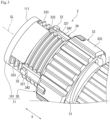
Fig. 1 is a perspective view illustrating a connector according to an aspect of the present disclosure; -
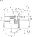
Fig. 2 is a cross-sectional view taken along line II-II ofFig. 1 ; -
Fig. 3 is a perspective view illustrating a plug of the connector ofFig. 1 ; -
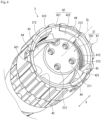
Fig. 4 is a perspective view illustrating a socket of the connector ofFig. 1 ; -
Fig. 5 is a plan view illustrating a state where a connection groove portion of the connector ofFig. 1 is exposed; -
Fig. 6 is a plan view illustrating a first modification of the connector ofFig. 1 ; and -
Fig. 7 is a plan view illustrating a second modification of the connector ofFig. 1 . - Hereinafter, an example of the present disclosure will be described with reference to the accompanying drawings. The following description is merely exemplary in nature and is not intended to limit the present disclosure, its applications, and uses of the present disclosure. The accompanying drawings are schematic, and ratios of dimensions and the like do not necessarily match actual ones.
- As illustrated in
Fig. 1 , aconnector 1 according to an aspect of the present disclosure includes aplug 2 and asocket 3 to which theplug 2 is detachably connected. Theplug 2 includes afirst connection member 10, and thesocket 3 includes asecond connection member 20 to which thefirst connection member 10 is detachably connected from a first direction (for example, an X direction). Theplug 2 and thesocket 3 are rotatably connected to each other via thefirst connection member 10 and thesecond connection member 20. - The
socket 3 is configured to be rotatable with respect to theplug 2 between a first position P1 (seeFig. 5 ) and a second position P2 in a circumferential direction with respect to a center line CL (illustrated inFig. 2 ) extending in a first direction (for example, in the X direction) that is an axial direction of the connector 1 (hereinafter, referred to as the circumferential direction). The first position P1 is a circumferential relative position of thesecond connection member 20 with respect to thefirst connection member 10 from which thefirst connection member 10 is detachable from the first direction X. The second position P2 is a circumferential relative position of thesecond connection member 20 with respect to thefirst connection member 10 from which thefirst connection member 10 cannot be detached from the first direction X. - As illustrated in
Figs. 1 and2 , thefirst connection member 10 includes afirst body portion 11 andclaw portions 32 protruding from thefirst body portion 11 in a radial direction with respect to the center line CL (hereinafter, referred to as the radial direction). In the present aspect, thefirst body portion 11 includes aplug body 101, a plug-side connection member 30 located at anend portion 111 close to thesocket 3 in the first direction X of theplug body 101, and a biasing member 13 (seeFig. 2 ). - As an example, the
plug body 101 has a substantially cylindrical shape extending along the first direction X. As illustrated inFig. 2 , theend portion 111 of theplug body 101 is provided with arecess 112 in which a plurality ofplug terminals 14 are accommodated. Therecess 112 includes an opening 113 facing thesocket 3. Eachplug terminal 14 protrudes in the first direction X from a bottom surface of therecess 112. Thecable 4 is connected to an end portion of theplug body 101 far from thesecond connection member 20 in the first direction X. - As illustrated in
Fig. 2 , the plug-side connection member 30 includes afirst member 33 and asecond member 34. In the present aspect, thefirst member 33 and thesecond member 34 are located outside theplug body 101 in the radial direction. - As an example, the
first member 33 has a substantially cylindrical shape and includes afirst portion 331 in contact with a part of theplug body 101 and asecond portion 332 located farther from thesocket 3 than thefirst portion 331 in the first direction X. Amale screw 333 is provided in thefirst portion 331. Agap 35 is provided between thesecond portion 332 and theplug body 101 in the radial direction. A part of thesecond member 34 and thebiasing member 13 are accommodated in thegap 35. - As illustrated in
Fig. 2 , thesecond member 34 includes afirst portion 341 located in thegap 35 of thefirst member 33 and asecond portion 342 located farther from theplug body 101 than thefirst member 33 in the radial direction. In the present aspect, thesecond member 34 is fixed to thefirst member 33. - As illustrated in
Fig. 3 , theclaw portion 32 is provided in thesecond portion 342 of thesecond member 34 and protrudes radially outward from thesecond portion 342. In the present aspect, thefirst connection member 10 includes a plurality ofclaw portions 32. As an example, each of theclaw portions 32 has a substantially rectangular parallelepiped shape, and includes anend surface 321 which is far from thesecond connection member 20 in the first direction X and is curved. Themale screw 333 is located between theclaw portions 32 adjacent in the circumferential direction. - As an example, the
biasing member 13 is configured by a coil spring. The biasingmember 13 is farther from thesocket 3 than thesecond member 34 in the first direction X in thegap 35, and biases thefirst member 33 and thesecond member 34 toward the direction approaching thesocket 3. - As illustrated in
Figs. 1 and2 , thesecond connection member 20 includes asecond body portion 21 andconnection groove portions 42 provided in thesecond body portion 21. Thesecond body portion 21 extends along the first direction X and is configured to be connectable to thefirst body portion 11 of thefirst connection member 10. In the present aspect, thesecond body portion 21 includes asocket body 201 and a socket-side connection member 41 located at anend portion 211 close to thesocket 3 in the first direction X of thesocket body 201. - For example, the
socket body 201 has a substantially columnar shape, and is configured to be accommodated in therecess 112 of theplug body 101. As illustrated inFig. 3 , theend portion 211 of thesocket body 201 is provided with a plurality ofaccommodating portions 212 each accommodating a socket terminal (not illustrated). As illustrated inFig. 1 , thecable 4 is connected to an end portion of thesocket body 201 far from thefirst connection member 10 in the first direction X. Each socket terminal is electrically connected to thecable 4. Theaccommodating portion 212 is configured to accommodate theplug terminal 14 in addition to the socket terminal. Theplug terminal 14 and the socket terminal are connected in theaccommodating portion 212, and theplug 2 and thesocket 3 are electrically connected. - As illustrated in
Figs. 2 and4 , for example, the socket-side connection member 41 has a substantially cylindrical shape, and a part of the socket-side connection member 41 is located outside thefirst body portion 11 in the radial direction. In the present aspect, the socket-side connection member 41 includes anend portion 414 which is far from thefirst connection member 10 in the first direction X and is connected and fixed to thesocket body 201. Agap 43 for accommodating thesocket body 201 in therecess 112 of theplug body 101 is formed between the socket-side connection member 41 and thesocket body 201 in the radial direction. In a state where thesocket body 201 is accommodated in therecess 112 of theplug body 101, theplug body 101, thefirst portion 331 of thefirst member 33 of thefirst connection member 10, and thesecond portion 342 of thesecond member 34 are located in thegap 43. - The socket-
side connection member 41 includes anend portion 411 facing thefirst connection member 10 in the first direction X, theend portion 411 being provided with a restrictingportion 44 provided at a position different from thefirst groove portion 421 of theconnection groove portion 42 to be described later. The restrictingportion 44 is configured to accommodate theclaw portion 32 and to restrict the rotation of thesocket 3 with respect to theplug 2 in the circumferential direction. - In the present aspect, as illustrated in
Fig. 5 , the restrictingportion 44 is configured by a notch which extends along the circumferential direction and is configured to accommodate theclaw portion 32 from the first direction X. The restrictingportion 44 is adjacent to an upstream side of thefirst groove portion 421 in the circumferential direction and in a direction in which thesecond connection member 20 moves from the first position P1 to the second position P2 (indicated by an arrow A), and includes one end in the circumferential direction connected to thefirst groove portion 421. The restrictingportion 44 has substantially the same length in circumferential direction as asecond groove portion 422 described later. - The
connection groove portion 42 is located in aportion 412 facing theplug 2 in the radial direction of the socket-side connection member 41, and is configured to accommodate theclaw portion 32. In the present exemplary aspect, the socket-side connection member 41 is provided with threeconnection groove portions 42 respectively corresponding to threeclaw portions 32. As illustrated inFig. 4 , afemale screw 413 that is fastenable to themale screw 333 of theplug 2 from the first direction X is provided between theconnection groove portions 42 adjacent in the circumferential direction. - As illustrated in
Fig. 5 , theconnection groove portion 42 includes afirst groove portion 421 and asecond groove portion 422. - The
first groove portion 421 extends along the first direction X from theend portion 411 of the socket-side connection member 41 facing thefirst connection member 10 in the first direction X. Thefirst groove portion 421 is configured to guide movement of theclaw portion 32 in the first direction X in a state where thesecond connection member 20 is located at the first position P1. Thesecond groove portion 422 is connected to an end portion of thefirst groove portion 421 far from thefirst connection member 10 in the first direction X. - The
second groove portion 422 extends along the circumferential direction, and is configured that theclaw portion 32 is movable in the circumferential direction. In the present aspect, when theclaw portion 32 is located at one circumferential end of thesecond groove portion 422, thesecond connection member 20 is located at thefirst position P 1, and when theclaw portion 32 is located at the other circumferential end of thesecond groove portion 422, thesecond connection member 20 is located at the second position P2. Thesecond groove portion 422 is configured to restrict movement of theclaw portion 32 in the first direction X and in a direction approaching theplug 2 in a state where thesecond connection member 20 is located at the second position P2. In the present aspect, arecess 423 along a curved shape of theend surface 321 of theclaw portion 32 is provided at an end portion of thesecond groove portion 422 closer to theplug 2 in the first direction X. - A
guide surface 424 configured to guide movement of theclaw portion 32 in the circumferential direction is provided between thefirst groove portion 421 and therecess 423 in the circumferential direction in thesecond groove portion 422. Theguide surface 424 is curved while being inclined in a direction away from theplug 2 in the first direction X as being away from thefirst groove portion 421 in the circumferential direction. - When the
plug 2 and thesocket 3 are connected by theclaw portion 32 of thefirst connection member 10 and theconnection groove portion 42 of thesecond connection member 20, thesecond connection member 20 is located at the first position P1 by aligning the positions of theplug 2 and thesocket 3 in the circumferential direction. In a state where thesecond connection member 20 is located at the first position P1, theplug 2 and thesocket 3 are brought close to each other until theclaw portion 32 reaches thesecond groove portion 422 through thefirst groove portion 421. When theclaw portion 32 reaches thesecond groove portion 422, thesecond connection member 20 is rotated until thesecond connection member 20 no longer rotates with respect to thefirst connection member 10, and thesecond connection member 20 is moved from the first position P1 to the second position P2. - In a state where the
plug 2 and thesocket 3 are connected to each other, as illustrated inFig. 2 , a sealingmember 50 seals between thefirst connection member 10 and thesecond connection member 20 to prevent contact of liquid, dust, or the like with the plug terminal and the socket terminal. - The
connector 1 can exhibit the following advantageous effects. - The
connector 1 includes theplug 2 including thefirst connection member 10 and thesocket 3 including thesecond connection member 20 to which thefirst connection member 10 is detachably connected from the first direction X. Thesecond connection member 20 is configured to be rotatable with respect to thefirst connection member 10 between the first position P1 where thefirst connection member 10 is detachable from the first direction X and the second position P2 where thefirst connection member 10 is not detachable from the first direction X in the circumferential direction with respect to the center line CL extending in the first direction X. Thefirst connection member 10 includes thefirst body portion 11 extending along the first direction X and theclaw portion 32 protruding from thefirst body portion 11 in the radial direction with respect to the center line CL. Thesecond connection member 20 includes thesecond body portion 21 that extends along the first direction and is configured to be connectable to thefirst body portion 11, a part of thesecond body portion 21 being located outside thefirst body portion 11 in the radial direction, and aconnection groove portion 42 which is located in a portion of thesecond body portion 21 facing thefirst body portion 11 and accommodates theclaw portion 32. Theconnection groove portion 42 includes thefirst groove portion 421 and thesecond groove portion 422. Thefirst groove portion 421 extends along the first direction from theend portion 411 of thesecond body portion 21 facing thefirst connection member 10, and is configured to guide the movement of theclaw portion 32 in the first direction X in a state where thesecond connection member 20 is located at the first position P1. Thesecond groove portion 422 is connected to the end portion of thefirst groove portion 421 far from thefirst connection member 10 in the first direction X, extends along the circumferential direction, and is configured that theclaw portion 32 is movable in the circumferential direction, and is configured to restrict the movement of theclaw portion 32 in the first direction X and in the direction approaching theplug 2 in a state where thesecond connection member 20 is located at the second position P2. Thesecond body portion 21 includes the restrictingportion 44 that is provided at a position different from thefirst groove portion 421 at theend portion 411 facing thefirst connection member 10, and is configured to accommodate theclaw portion 32 and to restrict the rotation of thesocket 3 with respect to theplug 2 in the circumferential direction. With such a configuration, even if a start position of rotational operation is wrong when theplug 2 and thesocket 3 are connected, a relative rotation of theplug 2 and thesocket 3 is restricted. As a result, it is possible to prevent a user from erroneously recognizing that the connection between theplug 2 and thesocket 3 is normally completed. - The restricting
portion 44 is configured by a notch that extends along the circumferential direction and is connected to thefirst groove portion 421, the notch being configured to accommodate theclaw portion 32 from the first direction X. With such a configuration, even if the start position of rotational operation is wrong when theplug 2 and thesocket 3 are connected, it is possible to prevent restriction of the relative rotation of theplug 2 and thesocket 3 toward a correct position while restricting the relative rotation of theplug 2 and thesocket 3 away from a correct position. - The restricting
portion 44 is adjacent to the upstream side of thefirst groove portion 421 in the circumferential direction and in the direction in which thesecond connection member 20 moves from the first position P1 to the second position P2. With such a configuration, it is possible to more reliably prevent the user from erroneously recognizing that the connection between theplug 2 and thesocket 3 is normally completed. - The
connector 1 may be configured as follows. - As illustrated in
Fig. 6 , the restrictingportion 44 may be configured to include aninclined surface 441. Theinclined surface 441 is located to be opposable to theclaw portion 32 in the first direction X, and is inclined in a direction away from thefirst connection member 10 in the first direction X as approaching thefirst groove portion 421 in the circumferential direction. With such a configuration, theclaw portion 32 accommodated in the restrictingportion 44 can be guided toward thefirst groove portion 421. In the above aspect, the plug-side connection member 30 provided with theclaw portion 32 is biased in the direction approaching thesocket 3 by the biasingmember 13. Therefore, theclaw portion 32 accommodated in the restrictingportion 44 can be more reliably guided toward thefirst groove portion 421. - The restricting
portion 44 is not limited to the case where the restrictingportion 44 is configured by a notch. For example, as illustrated inFig. 7 , the restrictingportion 44 may be configured by a groove independent of thefirst groove portion 421, the groove being configured to accommodate theclaw portion 32 from the first direction X. In theconnector 1 ofFig. 7 , the restrictingportion 44 is opened to theend portion 411 of the socket-side connection member 41, and is located at a position overlapping therecess 423 of thesecond groove portion 422 when viewed along the first direction X. Since the restrictingportion 44 ofFig. 7 restricts forward and reverse rotations of the accommodatedclaw portion 32 in the circumferential direction, it is possible to easily recognize an error in the start position of rotational operation. - The restricting
portion 44 is not limited to the case where the restrictingportion 44 is adj acent to the upstream side of thefirst groove portion 421 in the circumferential direction and in the direction in which thesecond connection member 20 moves from the first position P1 to the second position P2 (the direction of the arrow A inFig. 5 ). The restrictingportion 44 may be provided at any position of thesecond body portion 21 where the user can be prevented from erroneously recognizing that the connection between the plug and the socket is normally completed. For example, the restrictingportion 44 may be provided adjacent to a downstream side of thefirst groove portion 421 in the direction of the arrow A inFig. 5 . - The
connector 1 is configured that theplug 2 and thesocket 3 are connectable by screw connection using themale screw 333 and thefemale screw 413, and theplug 2 and thesocket 3 are connectable by snap-fit connection (bayonet connection) using theclaw portion 32 and theconnection groove portion 42, but is not limited thereto. For example, theconnector 1 may be configured that themale screw 333 and thefemale screw 413 are omitted and theplug 2 and thesocket 3 are connectable only by snap-fit connection. - Shapes and configurations of the
plug 2 and thesocket 3 are not limited to the above aspect, and may be freely changed within a range in which the present disclosure can be realized. - Various aspects of the present disclosure have been described above in detail with reference to the drawings. Finally, various aspects of the present disclosure will be described. In the following description, as an example, reference numerals are also added.
- A
connector 1 according to a first aspect of the present disclosure includes: - a
plug 2 including afirst connection member 10; and - a
socket 3 including asecond connection member 20 to which thefirst connection member 10 is detachably connected from a first direction, thesecond connection member 20 being configured to be rotatable with respect to thefirst connection member 10 between a first position P1 where thefirst connection member 10 is detachable from the first direction and a second position P2 where thefirst connection member 10 is not detachable from the first direction in a circumferential direction with respect to a center line CL extending in the first direction, - the
first connection member 10 includes:- a
first body portion 11 that extends along the first direction; and - a
claw portion 32 that protrudes from thefirst body portion 11 in a radial direction with respect to the center line CL,
- a
- the
second connection member 20 includes:- a
second body portion 21 that extends along the first direction and is configured to be connectable to thefirst body portion 11, a part of thesecond body portion 21 being located outside thefirst body portion 11 in the radial direction; and - a
connection groove portion 42 which is located in a portion of thesecond body portion 21 facing thefirst body portion 11 and accommodates theclaw portion 32,
- a
- the
connection groove portion 42 includes:- a
first groove portion 421 that extends along the first direction from anend portion 411 of thesecond body portion 21 facing thefirst connection member 10 and is configured to guide movement of theclaw portion 32 in the first direction in a state where thesecond connection member 20 is located at the first position P1; and - a
second groove portion 422 that is connected to an end portion of thefirst groove portion 421 far from thefirst connection member 10 in the first direction, extends along the circumferential direction, and is configured that theclaw portion 32 is movable in the circumferential direction, and is configured to restrict movement of theclaw portion 32 in the first direction and in a direction approaching theplug 2 in a state where thesecond connection member 20 is located at the second position P2, and
- a
- the
second body portion 21 includes
a restrictingportion 44 that is provided at a position different from thefirst groove portion 421 at an end portion facing thefirst connection member 10 and is configured to accommodate theclaw portion 32 and to restrict rotation of thesocket 3 with respect to theplug 2 in the circumferential direction. - In a
connector 1 according to a second aspect of the present disclosure, in theconnector 1 according to the first aspect, the restrictingportion 44 is configured by a notch that extends along the circumferential direction and is connected to thefirst groove portion 421, the notch being configured to accommodate theclaw portion 32 from the first direction. - In a
connector 1 according to a third aspect of the present disclosure, in theconnector 1 according to the second aspect, the restrictingportion 44 includes aninclined surface 441 that is located to be opposable to theclaw portion 32 in the first direction and is inclined in a direction away from thefirst connection member 10 in the first direction as approaching thefirst groove portion 421 in the circumferential direction. - In a
connector 1 according to a fourth aspect of the present disclosure, in theconnector 1 according to the first aspect, the restrictingportion 44 is configured by a groove independent of thefirst groove portion 421, the groove being configured to accommodate theclaw portion 32 from the first direction. - In a
connector 1 according to a fifth aspect of the present disclosure, in theconnector 1 according to any one of the first to fourth aspects, the restrictingportion 44 is adjacent to an upstream side of thefirst groove portion 421 in the circumferential direction and in a direction in which thesecond connection member 20 moves from the first position P1 toward the second position P2. - By appropriately combining any aspects or modifications among the various aspects or modifications, the effects of the respective aspects or modifications can be achieved. In addition, combinations of aspects, combinations of examples, or combinations of aspects and examples are possible, and combinations of features in different aspects or examples are also possible.
- Although the present disclosure has been fully described in connection with preferred aspects with reference to the accompanying drawings, various modifications and corrections will be apparent to those skilled in the art. Such modifications and corrections are to be understood as being included within the scope of the present disclosure as set forth in the appended claims.
- The connector of the present disclosure can be applied to, for example, an automobile machine tool.
Claims (5)
- A connector (1), characterized by comprising:a plug (2) including a first connection member (10); anda socket (3) including a second connection member (20) to which the first connection member (10) is detachably connected from a first direction, the second connection member (20) being configured to be rotatable with respect to the first connection member (10) between a first position (P1) where the first connection member (10) is detachable from the first direction and a second position (P2) where the first connection member (10) is not detachable from the first direction in a circumferential direction with respect to a center line (CL) extending in the first direction, whereinthe first connection member (10) includes:a first body portion (11) that extends along the first direction; anda claw portion (32) that protrudes from the first body portion (11) in a radial direction with respect to the center line (CL),the second connection member (20) includes:a second body portion (21) that extends along the first direction and is configured to be connectable to the first body portion (11), a part of the second body portion (21) being located outside the first body portion (11) in the radial direction; anda connection groove portion (42) which is located in a portion of the second body portion (21) facing the first body portion (11) and accommodates the claw portion (32),the connection groove portion (42) includes:a first groove portion (421) that extends along the first direction from an end portion (411) of the second body portion (21) facing the first connection member (10) and is configured to guide movement of the claw portion (32) in the first direction in a state where the second connection member (20) is located at the first position (P1); anda second groove portion (422) that is connected to an end portion of the first groove portion (421) far from the first connection member (10) in the first direction, extends along the circumferential direction, and is configured that the claw portion (32) is movable in the circumferential direction, and is configured to restrict movement of the claw portion (32) in the first direction and in a direction approaching the plug (2) in a state where the second connection member (20) is located at the second position (P2), andthe second body portion (21) includes
a restricting portion (44) that is provided at a position different from the first groove portion (421) at an end portion facing the first connection member (10), and is configured to accommodate the claw portion (32) and to restrict rotation of the socket (3) with respect to the plug (2) in the circumferential direction. - The connector (1) according to claim 1, wherein
the restricting portion (44) is configured by a notch that extends along the circumferential direction and is connected to the first groove portion (421), the notch being configured to accommodate the claw portion (32) from the first direction. - The connector (1) according to claim 2, wherein
the restricting portion (44) includes an inclined surface (441) that is located to be opposable to the claw portion (32) in the first direction and is inclined in a direction away from the first connection member (10) in the first direction as approaching the first groove portion (421) in the circumferential direction. - The connector (1) according to claim 1, wherein,
the restricting portion (44) is configured by a groove independent of the first groove portion (421), the groove being configured to accommodate the claw portion (32) from the first direction. - The connector (1) according to any one of claims 1 to 4, wherein,
the restricting portion (44) is adjacent to an upstream side of the first groove portion (421) in the circumferential direction and in a direction in which the second connection member (20) moves from the first position (P1) toward the second position (P2).
Applications Claiming Priority (1)
| Application Number | Priority Date | Filing Date | Title |
|---|---|---|---|
| JP2023069225A JP2024154964A (en) | 2023-04-20 | 2023-04-20 | connector |
Publications (1)
| Publication Number | Publication Date |
|---|---|
| EP4451484A1 true EP4451484A1 (en) | 2024-10-23 |
Family
ID=90670531
Family Applications (1)
| Application Number | Title | Priority Date | Filing Date |
|---|---|---|---|
| EP24169553.5A Pending EP4451484A1 (en) | 2023-04-20 | 2024-04-10 | Connector |
Country Status (4)
| Country | Link |
|---|---|
| US (1) | US20240356277A1 (en) |
| EP (1) | EP4451484A1 (en) |
| JP (1) | JP2024154964A (en) |
| CN (1) | CN118825720A (en) |
Citations (3)
| Publication number | Priority date | Publication date | Assignee | Title |
|---|---|---|---|---|
| JP2007103046A (en) | 2005-09-30 | 2007-04-19 | Omron Corp | connector |
| CN111937252A (en) * | 2018-04-04 | 2020-11-13 | 菲尼克斯电气公司 | Electrical plug connector part with locking means and electrical plug connection system |
| JP2022084437A (en) * | 2020-11-26 | 2022-06-07 | オムロン株式会社 | connector |
-
2023
- 2023-04-20 JP JP2023069225A patent/JP2024154964A/en active Pending
-
2024
- 2024-04-10 EP EP24169553.5A patent/EP4451484A1/en active Pending
- 2024-04-11 CN CN202410433868.4A patent/CN118825720A/en active Pending
- 2024-04-12 US US18/633,911 patent/US20240356277A1/en active Pending
Patent Citations (3)
| Publication number | Priority date | Publication date | Assignee | Title |
|---|---|---|---|---|
| JP2007103046A (en) | 2005-09-30 | 2007-04-19 | Omron Corp | connector |
| CN111937252A (en) * | 2018-04-04 | 2020-11-13 | 菲尼克斯电气公司 | Electrical plug connector part with locking means and electrical plug connection system |
| JP2022084437A (en) * | 2020-11-26 | 2022-06-07 | オムロン株式会社 | connector |
Also Published As
| Publication number | Publication date |
|---|---|
| US20240356277A1 (en) | 2024-10-24 |
| CN118825720A (en) | 2024-10-22 |
| JP2024154964A (en) | 2024-10-31 |
Similar Documents
| Publication | Publication Date | Title |
|---|---|---|
| US7329133B2 (en) | Connector | |
| US8992240B2 (en) | Connector | |
| KR101860260B1 (en) | Connector device | |
| CN111033905B (en) | Terminals and Connectors for Connectors | |
| JPH11339890A (en) | Connector with locking mechanism | |
| US10305223B2 (en) | Connector with projecting sub-connector lance | |
| US20210013675A1 (en) | Lever-type connector | |
| CN111066208A (en) | Connector with a locking member | |
| CN111525339B9 (en) | Lever-type connector | |
| US20210066850A1 (en) | Connector | |
| JP2020087518A (en) | Corrugated tube holder and wire harness | |
| US12249794B2 (en) | Connector having lever for promoting connection of housing and mating housing | |
| JP2009158151A (en) | Connector | |
| JP2006040838A (en) | Male / female connector mating structure | |
| CN115699471A (en) | Connecting assembly and connector with rotational position assurance | |
| US20240356277A1 (en) | Connector | |
| EP2051335B1 (en) | A connector | |
| JP4904094B2 (en) | connector | |
| JP7512866B2 (en) | connector | |
| US12308571B2 (en) | Connector with detecting member | |
| US20060240698A1 (en) | Electrical connector | |
| US20250038455A1 (en) | Lever-type connector | |
| EP3863126B1 (en) | Lever type connector | |
| WO2022163334A1 (en) | Lever-type connector | |
| WO2020017271A1 (en) | Lever-type connector |
Legal Events
| Date | Code | Title | Description |
|---|---|---|---|
| PUAI | Public reference made under article 153(3) epc to a published international application that has entered the european phase |
Free format text: ORIGINAL CODE: 0009012 |
|
| STAA | Information on the status of an ep patent application or granted ep patent |
Free format text: STATUS: REQUEST FOR EXAMINATION WAS MADE |
|
| 17P | Request for examination filed |
Effective date: 20240410 |
|
| AK | Designated contracting states |
Kind code of ref document: A1 Designated state(s): AL AT BE BG CH CY CZ DE DK EE ES FI FR GB GR HR HU IE IS IT LI LT LU LV MC ME MK MT NL NO PL PT RO RS SE SI SK SM TR |
|
| GRAP | Despatch of communication of intention to grant a patent |
Free format text: ORIGINAL CODE: EPIDOSNIGR1 |
|
| STAA | Information on the status of an ep patent application or granted ep patent |
Free format text: STATUS: GRANT OF PATENT IS INTENDED |
|
| RIC1 | Information provided on ipc code assigned before grant |
Ipc: H01R 13/625 20060101AFI20260630BHEP Ipc: H01R 24/00 20110101ALI20260630BHEP Ipc: H01R 24/86 20110101ALN20260630BHEP |