EP4451429A1 - Battery cell - Google Patents
Battery cell Download PDFInfo
- Publication number
- EP4451429A1 EP4451429A1 EP24163587.9A EP24163587A EP4451429A1 EP 4451429 A1 EP4451429 A1 EP 4451429A1 EP 24163587 A EP24163587 A EP 24163587A EP 4451429 A1 EP4451429 A1 EP 4451429A1
- Authority
- EP
- European Patent Office
- Prior art keywords
- pair
- oblique
- insulating sheet
- sides
- portions
- Prior art date
- Legal status (The legal status is an assumption and is not a legal conclusion. Google has not performed a legal analysis and makes no representation as to the accuracy of the status listed.)
- Pending
Links
Images



Classifications
-
- H—ELECTRICITY
- H01—ELECTRIC ELEMENTS
- H01M—PROCESSES OR MEANS, e.g. BATTERIES, FOR THE DIRECT CONVERSION OF CHEMICAL ENERGY INTO ELECTRICAL ENERGY
- H01M50/00—Constructional details or processes of manufacture of the non-active parts of electrochemical cells other than fuel cells, e.g. hybrid cells
- H01M50/10—Primary casings; Jackets or wrappings
- H01M50/147—Lids or covers
- H01M50/148—Lids or covers characterised by their shape
- H01M50/15—Lids or covers characterised by their shape for prismatic or rectangular cells
-
- H—ELECTRICITY
- H01—ELECTRIC ELEMENTS
- H01M—PROCESSES OR MEANS, e.g. BATTERIES, FOR THE DIRECT CONVERSION OF CHEMICAL ENERGY INTO ELECTRICAL ENERGY
- H01M50/00—Constructional details or processes of manufacture of the non-active parts of electrochemical cells other than fuel cells, e.g. hybrid cells
- H01M50/50—Current conducting connections for cells or batteries
- H01M50/572—Means for preventing undesired use or discharge
- H01M50/584—Means for preventing undesired use or discharge for preventing incorrect connections inside or outside the batteries
- H01M50/59—Means for preventing undesired use or discharge for preventing incorrect connections inside or outside the batteries characterised by the protection means
- H01M50/593—Spacers; Insulating plates
-
- H—ELECTRICITY
- H01—ELECTRIC ELEMENTS
- H01M—PROCESSES OR MEANS, e.g. BATTERIES, FOR THE DIRECT CONVERSION OF CHEMICAL ENERGY INTO ELECTRICAL ENERGY
- H01M10/00—Secondary cells; Manufacture thereof
- H01M10/05—Accumulators with non-aqueous electrolyte
- H01M10/052—Li-accumulators
- H01M10/0525—Rocking-chair batteries, i.e. batteries with lithium insertion or intercalation in both electrodes; Lithium-ion batteries
-
- H—ELECTRICITY
- H01—ELECTRIC ELEMENTS
- H01M—PROCESSES OR MEANS, e.g. BATTERIES, FOR THE DIRECT CONVERSION OF CHEMICAL ENERGY INTO ELECTRICAL ENERGY
- H01M10/00—Secondary cells; Manufacture thereof
- H01M10/60—Heating or cooling; Temperature control
- H01M10/65—Means for temperature control structurally associated with the cells
- H01M10/653—Means for temperature control structurally associated with the cells characterised by electrically insulating or thermally conductive materials
-
- H—ELECTRICITY
- H01—ELECTRIC ELEMENTS
- H01M—PROCESSES OR MEANS, e.g. BATTERIES, FOR THE DIRECT CONVERSION OF CHEMICAL ENERGY INTO ELECTRICAL ENERGY
- H01M50/00—Constructional details or processes of manufacture of the non-active parts of electrochemical cells other than fuel cells, e.g. hybrid cells
- H01M50/10—Primary casings; Jackets or wrappings
- H01M50/102—Primary casings; Jackets or wrappings characterised by their shape or physical structure
- H01M50/103—Primary casings; Jackets or wrappings characterised by their shape or physical structure prismatic or rectangular
-
- H—ELECTRICITY
- H01—ELECTRIC ELEMENTS
- H01M—PROCESSES OR MEANS, e.g. BATTERIES, FOR THE DIRECT CONVERSION OF CHEMICAL ENERGY INTO ELECTRICAL ENERGY
- H01M50/00—Constructional details or processes of manufacture of the non-active parts of electrochemical cells other than fuel cells, e.g. hybrid cells
- H01M50/10—Primary casings; Jackets or wrappings
- H01M50/116—Primary casings; Jackets or wrappings characterised by the material
- H01M50/124—Primary casings; Jackets or wrappings characterised by the material having a layered structure
-
- H—ELECTRICITY
- H01—ELECTRIC ELEMENTS
- H01M—PROCESSES OR MEANS, e.g. BATTERIES, FOR THE DIRECT CONVERSION OF CHEMICAL ENERGY INTO ELECTRICAL ENERGY
- H01M50/00—Constructional details or processes of manufacture of the non-active parts of electrochemical cells other than fuel cells, e.g. hybrid cells
- H01M50/10—Primary casings; Jackets or wrappings
- H01M50/14—Primary casings; Jackets or wrappings for protecting against damage caused by external factors
-
- H—ELECTRICITY
- H01—ELECTRIC ELEMENTS
- H01M—PROCESSES OR MEANS, e.g. BATTERIES, FOR THE DIRECT CONVERSION OF CHEMICAL ENERGY INTO ELECTRICAL ENERGY
- H01M50/00—Constructional details or processes of manufacture of the non-active parts of electrochemical cells other than fuel cells, e.g. hybrid cells
- H01M50/10—Primary casings; Jackets or wrappings
- H01M50/183—Sealing members
- H01M50/186—Sealing members characterised by the disposition of the sealing members
-
- H—ELECTRICITY
- H01—ELECTRIC ELEMENTS
- H01M—PROCESSES OR MEANS, e.g. BATTERIES, FOR THE DIRECT CONVERSION OF CHEMICAL ENERGY INTO ELECTRICAL ENERGY
- H01M10/00—Secondary cells; Manufacture thereof
- H01M10/60—Heating or cooling; Temperature control
- H01M10/64—Heating or cooling; Temperature control characterised by the shape of the cells
- H01M10/647—Prismatic or flat cells, e.g. pouch cells
-
- Y—GENERAL TAGGING OF NEW TECHNOLOGICAL DEVELOPMENTS; GENERAL TAGGING OF CROSS-SECTIONAL TECHNOLOGIES SPANNING OVER SEVERAL SECTIONS OF THE IPC; TECHNICAL SUBJECTS COVERED BY FORMER USPC CROSS-REFERENCE ART COLLECTIONS [XRACs] AND DIGESTS
- Y02—TECHNOLOGIES OR APPLICATIONS FOR MITIGATION OR ADAPTATION AGAINST CLIMATE CHANGE
- Y02E—REDUCTION OF GREENHOUSE GAS [GHG] EMISSIONS, RELATED TO ENERGY GENERATION, TRANSMISSION OR DISTRIBUTION
- Y02E60/00—Enabling technologies; Technologies with a potential or indirect contribution to GHG emissions mitigation
- Y02E60/10—Energy storage using batteries
Definitions
- the present invention relates to a battery cell.
- Japanese Patent Laying-Open No. 2013-33668 discloses a battery cell including: an exterior container having a prismatic shape; and an insulating film that covers the exterior container.
- a battery cell including: a case body forming an external appearance in the form of a rectangular parallelepiped; and an insulating sheet that covers the case body by folding the insulating sheet.
- a short-circuit current may be generated or electric leakage may occur.
- the insulating sheet is provided with the trapezoidal portion adhered to the second side surface of the case body, a water entry path from the outside to the second side surface can be set at a high position with respect to the bottom surface of the case body. Further, since the insulating sheet is provided with the triangular portion overlapping with the trapezoidal portion, a water entry path to the second side surface of the case body through the upper side of the trapezoidal portion can be closed using the adhesive surface of the second side portion. With these, water can be more securely prevented from entering the battery cell from the outside.
- the trapezoidal portion further includes an upper side extending parallel to the lower side and connecting the pair of first oblique sides
- the pair of second side portions include overlapping portions that overlap with each other on the second side surface
- a length of the upper side is equal to or more than a length of each of the overlapping portions in a direction in which the upper side extends.
- interference can be avoided between the second side and the first oblique side corresponding to the folded portion of the trapezoidal portion and the triangular portion.
- the trapezoidal portion further includes an upper side extending parallel to the lower side and connecting the pair of first oblique sides, and a length between the lower side and the upper side is equal to or more than a length of the lower side.
- the water entry path from the outside to the second side surface of the case body can be set at a higher position with respect to the bottom surface of the case body.
- Fig. 1 is a perspective view showing a battery cell according to an embodiment of the present invention.
- battery cell 100 according to the present embodiment is a lithium ion battery.
- Battery cell 100 has an output density of 8000 W/L or more.
- Battery cell 100 has a prismatic shape and has a thin plate shape in the form of a rectangular parallelepiped.
- a "Y axis” is defined as an axis extending in a thickness direction of battery cell 100
- a "Z axis” is defined as an axis orthogonal to the Y axis and extending in an upward/downward direction
- an "X axis” is defined as an axis extending in a direction orthogonal to the Y axis and the Z axis.
- a plurality of battery cells 100 are stacked in the Y axis direction and electrically connected in series with each other, thereby forming a battery module.
- the battery module is mounted as a power supply for driving a vehicle such as a hybrid electric vehicle (HEV), a plug-in hybrid electric vehicle (PHEV), or a battery electric vehicle (BEV).
- HEV hybrid electric vehicle
- PHEV plug-in hybrid electric vehicle
- BEV battery electric vehicle
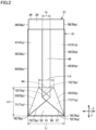
- Fig. 2 is a side view showing the battery cell when viewed in a direction indicated by an arrow II in Fig. 1 .
- Fig. 3 is a perspective view showing a first step of assembling the battery cell in Fig. 1 .
- battery cell 100 has a case body 21.
- Case body 21 is constituted of a housing having a rectangular parallelepiped shape.
- Case body 21 is composed of a metal.
- Case body 21 accommodates an electrode assembly and an electrolyte solution.
- case body 21 includes a bottom surface 27, a pair of first side surfaces 28 (28p, 28q), a pair of second side surfaces 29 facing each other, and a top surface 26.
- Bottom surface 27 is disposed at a bottom portion of case body 21.
- Top surface 26 is disposed at a top portion of case body 21.
- Each of bottom surface 27 and top surface 26 is constituted of a flat surface orthogonal to the Z axis.
- bottom surface 27 has a rectangular shape having long sides each extending in the X axis direction and short sides each extending in the Y axis direction.
- first side surfaces 28 face each other in the Y axis direction.
- Each of first side surfaces 28 is constituted of a flat surface orthogonal to the Y axis.
- first side surface 28 has a rectangular shape having long sides each extending in the X axis direction and short sides each extending in the Z axis direction.
- First side surface 28 has the largest area among the plurality of side surfaces of case body 21.
- the pair of second side surfaces 29 face each other in the X axis direction.
- Each of second side surfaces 29 is constituted of a flat surface orthogonal to the X axis.
- Second side surface 29 has an area smaller than that of first side surface 28.
- second side surface 29 has a rectangular shape having short sides each extending in the Y axis direction and long sides each extending in the Z axis direction.
- Second side surface 29 has a first side 31 and a pair of second sides 32 (32p, 32q).
- First side 31 forms a boundary between second side surface 29 and bottom surface 27.
- First side 31 corresponds to a short side of second side surface 29 extending in the Y axis direction.
- the pair of second sides 32 rise from first side 31 and respectively form boundaries with the pair of first side surfaces 28.
- Second sides 32 correspond to the long sides of second side surface 29 extending in the Z axis direction.
- a lower end portion of each of second sides 32 intersects an end portion of first side 31 in the Y axis direction so as to form a corner portion of second side surface 29.
- First side 31 and second side 32p intersect at an intersection 76p.
- First side 31 and second side 32q intersect at an intersection 76q.
- battery cell 100 further has a gas-discharge valve 16.
- Gas-discharge valve 16 is provided on top surface 26.
- Gas-discharge valve 16 is provided at a central portion of top surface 26 in the X axis direction.
- Battery cell 100 further has electrode terminals 11 that are a pair of a positive electrode terminal 11P and a negative electrode terminal 11N. Electrode terminals 11 are provided on top surface 26. Positive electrode terminal 11P and negative electrode terminal 11N are provided on both sides beside gas-discharge valve 16 in the X axis direction.
- Insulating sheet 51 is a sheet having a strip shape and having a long-side direction that is one direction and a width direction that is a direction orthogonal to the one direction. Insulating sheet 51 has a rectangular shape when viewed in a plan view. Insulating sheet 51 is composed of a resin.
- the material of insulating sheet 51 may be polypropylene (PP), polyethylene terephthalate (PET), polyphenylene sulfide (PPS), polyimide (PI), or polyolefin (PO).
- Insulating sheet 51 covers case body 21. Insulating sheet 51 is folded to cover bottom surface 27, the pair of first side surfaces 28, and the pair of second side surfaces 29 of case body 21.
- One of front surface and rear surface of insulating sheet 51 is an adhesive surface 51a having an adhesive agent applied thereon, and the other of the front surface and rear surface of insulating sheet 51 is a non-adhesive surface 51b having no adhesive agent applied thereon.
- Insulating sheet 51 is basically provided such that adhesive surface 51a faces case body 21.
- Bottom surface 27 is entirely covered with insulating sheet 51.
- the pair of first side surfaces 28 and the pair of second side surfaces 29 are partially exposed from insulating sheet 51; however, the pair of first side surfaces 28 and the pair of second side surfaces 29 may be entirely covered with insulating sheet 51.
- Fig. 4 is a side view showing a second step of assembling the battery cell in Fig. 1 .
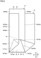
- Fig. 5 is a side view showing a third step of assembling the battery cell in Fig. 1 .
- a total length (thickness) of case body 21 in the Y axis direction in Figs. 2 to 5 is illustrated to be larger than the thickness of case body 21 in Fig. 1 .
- insulating sheet 51 covers both of the pair of second side surfaces 29 in the same manner.
- insulating sheet 51 has a bottom portion 61 and a pair of first side portions 62 (62p, 62q). Bottom portion 61 is adhered to bottom surface 27. Bottom portion 61 has a rectangular shape corresponding to bottom surface 27 when viewed in a plan view. The pair of first side portions 62 (first side portion 62p and first side portion 62q) are adhered to the pair of first side surfaces 28 (first side surface 28p and first side surface 28q), respectively. First side portion 62 is folded from bottom portion 61 along the long side of first side portion 62 extending in the X axis direction. First side portion 62 has a rectangular shape corresponding to first side surface 28 when viewed in a plan view.
- insulating sheet 51 further has a trapezoidal portion 52.
- Trapezoidal portion 52 is adhered to second side surface 29.
- Trapezoidal portion 52 has a trapezoidal shape when viewed in a plan view.
- Trapezoidal portion 52 is folded from bottom portion 61 along first side 31 of second side surface 29.
- Trapezoidal portion 52 has an upper side 54, a lower side 56, and a pair of first oblique sides 53 (53p, 53q). Upper side 54 and lower side 56 extend parallel to each other. Upper side 54 connects first oblique side 53p and first oblique side 53q. The pair of first oblique sides 53 extend between upper side 54 and lower side 56. The pair of first oblique sides 53 are provided in line symmetry with respect to the central line of second side surface 29 extending in the Z axis direction.
- Lower side 56 extends in the Y axis direction. Lower side 56 overlaps with first side 31 of second side surface 29.
- Upper side 54 extends in the Y axis direction at a position away from first side 31 in the Z axis direction. A length of upper side 54 in the Y axis direction is smaller than a length of lower side 56 in the Y axis direction.
- First oblique sides 53 extend in oblique directions with respect to first side 31 and second sides 32.
- First oblique side 53p extends from intersection 76p between first side 31 and second side 32p.
- First oblique side 53q extends from intersection 76q between first side 31 and second side 32q.
- An angle between first side 31 and each first oblique side 53 may be 45° or more or may be less than 45°.
- Insulating sheet 51 further has a pair of triangular portions 71 (71p, 71q).
- the pair of triangular portions 71 are disposed on second side surface 29.
- the pair of triangular portions 71 overlap with trapezoidal portion 52 on second side surface 29.
- Triangular portion 71p is folded from trapezoidal portion 52 along first oblique side 53p.
- Triangular portion 71q is folded from trapezoidal portion 52 along first oblique side 53q.
- Triangular portion 71p and triangular portion 71q partially overlap with each other on trapezoidal portion 52.
- Each of triangular portions 71 includes a corresponding one of first oblique sides 53 (53p, 53q), a second oblique side 72 (72p, 72q), and a third oblique side 73 (73p, 73q).
- Triangular portion 71 shares first oblique side 53 with trapezoidal portion 52.
- First oblique side 53 is a folded portion of triangular portion 71 from trapezoidal portion 52.
- Second oblique side 72p extends from intersection 76p between first side 31 and first oblique side 53p.
- Second oblique side 72q extends from intersection 76q between first side 31 and first oblique side 53q.
- Second oblique side 72p and second oblique side 72q intersect each other on the central line of second side surface 29 extending in the Z axis direction.
- Third oblique side 73 connects first oblique side 53 and second oblique side 72.
- Third oblique side 73p extends between upper side 54 and first oblique side 53p from an intersection of upper side 54 and first oblique side 53p.
- Third oblique side 73q extends between upper side 54 and first oblique side 53q from an intersection of upper side 54 and first oblique side 53q.
- Third oblique side 73p and third oblique side 73q intersect each other on the central line of second side surface 29 extending in the Z axis direction.
- Insulating sheet 51 further has a pair of second side portions 41 (41p, 41q).
- the pair of second side portions 41 overlaps with second side surface 29.
- Second side portion 41p is folded from triangular portion 71p along second oblique side 72p, and is folded from first side portion 62p along second side 32p.
- Second side portion 41q is folded from triangular portion 71q along second oblique side 72q, and is folded from first side portion 62q along second side 32q.
- the pair of second side portions 41 have overlapping portions 46. Second side portion 41p and second side portion 41q overlap with each other on second side surface 29 at overlapping portions 46. At overlapping portions 46, second side portion 41p overlaps with second side surface 29, and second side portion 41q overlaps with second side portion 41p. At a position at which triangular portion 71p and triangular portion 71q partially overlap with each other, trapezoidal portion 52, triangular portion 71p, second side portion 41p, triangular portion 71q, and second side portion 41q are stacked on second side surface 29 in this order.
- Second side portion 41p is adhered to a portion of second side surface 29, triangular portion 71p, and a portion of trapezoidal portion 52.
- Second side portion 41q is adhered to a portion of second side surface 29, a portion of second side portion 41p, triangular portion 71q, and a portion of the trapezoidal portion.
- a length Lk of upper side 54 is equal to or more than a length Lj of each of overlapping portions 46 in the Y axis direction in which upper side 54 extends (Lk>Lj).
- bottom portion 61 is provided in insulating sheet 51.
- case body 21 is placed on insulating sheet 51 having a strip shape such that adhesive surface 51a of insulating sheet 51 and bottom surface 27 of case body 21 face each other. Insulating sheet 51 is adhered to bottom surface 27.
- the long-side direction of insulating sheet 51 corresponds to the X axis direction
- the short-side direction (width direction) of insulating sheet 51 corresponds to the Y axis direction.
- the length of insulating sheet 51 in the X axis direction is larger than the length of case body 21 in the X axis direction
- the length of insulating sheet 51 in the Y axis direction is larger than the length of case body 21 in the Y axis direction.
- first side portion 62 is provided in insulating sheet 51. Specifically, insulating sheet 51 is folded by 90° along the long side of first side surface 28 extending in the X axis direction. Insulating sheet 51 is adhered to first side surface 28.
- trapezoidal portion 52 is provided in insulating sheet 51. Specifically, insulating sheet 51 is folded at 90° along first side 31 of second side surface 29. Insulating sheet 51 is adhered to second side surface 29 in a range corresponding to the trapezoidal shape of trapezoidal portion 52.
- triangular portion 71p and second side portion 41p are provided in insulating sheet 51.
- insulating sheet 51 is folded toward the forward side along first oblique side 53p of trapezoidal portion 52, and further folded toward the forward side along second oblique side 72p of triangular portion 71p. Insulating sheet 51 is adhered to triangular portion 71p, a portion of trapezoidal portion 52, and a portion of second side surface 29.
- triangular portion 71q and second side portion 41q are provided in insulating sheet 51.
- insulating sheet 51 is folded toward the forward side along first oblique side 53q of trapezoidal portion 52, and further folded toward the forward side along second oblique side 72q of triangular portion 71q.
- Insulating sheet 51 is adhered to triangular portion 71q, a portion of trapezoidal portion 52, a portion of second side surface 29, and a portion of second side portion 41p.
- insulating sheet 51 is provided with trapezoidal portion 52 adhered to second side surface 29 of case body 21, a water entry path from the outside to second side surface 29 can be set at a high position with respect to bottom surface 27 of case body 21. Further, since insulating sheet 51 is provided with triangular portion 71 overlapping with trapezoidal portion 52, a water entry path to second side surface 29 of case body 21 through upper side 54 of trapezoidal portion 52 can be closed using adhesive surface 51a of second side portion 41. Therefore, water can be more securely prevented from entering battery cell 100 from the outside.
- a length Lh between lower side 56 and upper side 54 may be equal to or more than length Li of lower side 56 (Lh ⁇ Li). According to such a configuration, the water entry path from the outside to second side surface 29 of battery cell 100 can be set at a higher position with respect to bottom surface 27 of case body 21.
Landscapes
- Chemical & Material Sciences (AREA)
- Chemical Kinetics & Catalysis (AREA)
- Electrochemistry (AREA)
- General Chemical & Material Sciences (AREA)
- Engineering & Computer Science (AREA)
- Manufacturing & Machinery (AREA)
- Materials Engineering (AREA)
- Sealing Battery Cases Or Jackets (AREA)
Abstract
A battery cell includes: a case body (21) having a second side surface (29); and an insulating sheet (51) that covers the case body (21). The insulating sheet (51) has: a trapezoidal portion (52) having a trapezoidal shape including a lower side and a pair of first oblique sides (53), the lower side being defined by a first side (31) of the second side surface (29), the trapezoidal portion (52) being adhered to the second side surface (29); and a pair of triangular portions (71) folded from the trapezoidal portion (52) along the pair of first oblique sides (53). Each of the triangular portions (71) includes a corresponding one of the first oblique sides (53), a second oblique side (72), and a third oblique side (73). The insulating sheet (51) further has a pair of second side portions (41) overlapping with the second side surface (29) with the pair of second side portions (41) being folded from the triangular portions (71) along the pair of second oblique sides (72).
Description
- This nonprovisional application is based on
Japanese Patent Application No. 2023-064672 filed on April 12, 2023 - The present invention relates to a battery cell.
- For example,
Japanese Patent Laying-Open No. 2013-33668 - As disclosed in
Japanese Patent Laying-Open No. 2013-33668 - Thus, it is an object of the present invention to solve the above-described problem and to provide a battery cell so as to more securely prevent entry of water.
- A battery cell comprising: a case body having a bottom surface, a pair of first side surfaces, and a second side surface, the pair of first side surfaces each rising from the bottom surface and facing each other, the second side surface rising from the bottom surface and having an area smaller than an area of each of the first side surfaces, the case body forming an external appearance in a form of a rectangular parallelepiped; and an insulating sheet that covers the case body by applying an adhesive agent to one of a front surface and a rear surface of the insulating sheet and folding the insulating sheet, the insulating sheet having a strip shape, wherein the second side surface includes a first side and a pair of second sides, the first side forming a boundary with the bottom surface, the pair of second sides each rising from the first side and respectively forming boundaries with the pair of first side surfaces, the insulating sheet has a bottom portion adhered to the bottom surface, a pair of first side portions respectively adhered to the pair of first side surfaces, a trapezoidal portion having a trapezoidal shape including a lower side and a pair of first oblique sides, the lower side being defined by the first side with the trapezoidal portion being folded along the first side from the bottom portion, the pair of first oblique sides extending in oblique directions with respect to the second sides from intersections of the first side and the second sides respectively, the trapezoidal portion being adhered to the second side surface, and a pair of triangular portions overlapping with the trapezoidal portion with the pair of triangular portions being folded from the trapezoidal portion along the pair of first oblique sides, each of the triangular portions includes a corresponding one of the first oblique sides, a second oblique side, and a third oblique side, the second oblique side extending between the first oblique side and the first side from an intersection of the first side and a corresponding one of the second sides, the third oblique side connecting the first oblique side and the second oblique side, and the insulating sheet further has a pair of second side portions overlapping with the second side surface with the pair of second side portions being folded from the triangular portions along the pair of second oblique sides and the pair of second side portions being folded from the pair of first side portions along the second side.
- According to the battery cell thus configured, since the insulating sheet is provided with the trapezoidal portion adhered to the second side surface of the case body, a water entry path from the outside to the second side surface can be set at a high position with respect to the bottom surface of the case body. Further, since the insulating sheet is provided with the triangular portion overlapping with the trapezoidal portion, a water entry path to the second side surface of the case body through the upper side of the trapezoidal portion can be closed using the adhesive surface of the second side portion. With these, water can be more securely prevented from entering the battery cell from the outside.
- The battery cell according to [1], wherein the trapezoidal portion further includes an upper side extending parallel to the lower side and connecting the pair of first oblique sides, the pair of second side portions include overlapping portions that overlap with each other on the second side surface, and a length of the upper side is equal to or more than a length of each of the overlapping portions in a direction in which the upper side extends.
- According to the battery cell thus configured, interference can be avoided between the second side and the first oblique side corresponding to the folded portion of the trapezoidal portion and the triangular portion.
- The battery cell according to [1] or [2], wherein the trapezoidal portion further includes an upper side extending parallel to the lower side and connecting the pair of first oblique sides, and a length between the lower side and the upper side is equal to or more than a length of the lower side.
- According to the battery cell thus configured, the water entry path from the outside to the second side surface of the case body can be set at a higher position with respect to the bottom surface of the case body.
- The foregoing and other objects, features, aspects and advantages of the present invention will become more apparent from the following detailed description of the present invention when taken in conjunction with the accompanying drawings.
-
-
Fig. 1 is a perspective view showing a battery cell according to an embodiment of the present invention. -
Fig. 2 is a side view showing the battery cell when viewed in a direction indicated by an arrow II inFig. 1 . -
Fig. 3 is a perspective view showing a first step of assembling the battery cell inFig. 1 . -
Fig. 4 is a side view showing a second step of assembling the battery cell inFig. 1 . -
Fig. 5 is a side view showing a third step of assembling the battery cell inFig. 1 . - Embodiments of the present invention will be described with reference to figures. It should be noted that in the figures referred to below, the same or corresponding members are denoted by the same reference characters.
-
Fig. 1 is a perspective view showing a battery cell according to an embodiment of the present invention. Referring toFig. 1 ,battery cell 100 according to the present embodiment is a lithium ion battery.Battery cell 100 has an output density of 8000 W/L or more.Battery cell 100 has a prismatic shape and has a thin plate shape in the form of a rectangular parallelepiped. - In the present specification, for convenience of description of the structure of
battery cell 100, a "Y axis" is defined as an axis extending in a thickness direction ofbattery cell 100, a "Z axis" is defined as an axis orthogonal to the Y axis and extending in an upward/downward direction, and an "X axis" is defined as an axis extending in a direction orthogonal to the Y axis and the Z axis. - Typically, a plurality of
battery cells 100 are stacked in the Y axis direction and electrically connected in series with each other, thereby forming a battery module. The battery module is mounted as a power supply for driving a vehicle such as a hybrid electric vehicle (HEV), a plug-in hybrid electric vehicle (PHEV), or a battery electric vehicle (BEV). -
Fig. 2 is a side view showing the battery cell when viewed in a direction indicated by an arrow II inFig. 1 .Fig. 3 is a perspective view showing a first step of assembling the battery cell inFig. 1 . - Referring to
Figs. 1 to 3 ,battery cell 100 has acase body 21.Case body 21 is constituted of a housing having a rectangular parallelepiped shape.Case body 21 is composed of a metal.Case body 21 accommodates an electrode assembly and an electrolyte solution. - As shown in
Fig. 3 ,case body 21 includes abottom surface 27, a pair of first side surfaces 28 (28p, 28q), a pair ofsecond side surfaces 29 facing each other, and atop surface 26.Bottom surface 27 is disposed at a bottom portion ofcase body 21.Top surface 26 is disposed at a top portion ofcase body 21. Each ofbottom surface 27 andtop surface 26 is constituted of a flat surface orthogonal to the Z axis. When viewed in a plan view,bottom surface 27 has a rectangular shape having long sides each extending in the X axis direction and short sides each extending in the Y axis direction. - The pair of first side surfaces 28 (
first side surface 28p andfirst side surface 28q) face each other in the Y axis direction. Each offirst side surfaces 28 is constituted of a flat surface orthogonal to the Y axis. When viewed in a plan view,first side surface 28 has a rectangular shape having long sides each extending in the X axis direction and short sides each extending in the Z axis direction.First side surface 28 has the largest area among the plurality of side surfaces ofcase body 21. The pair ofsecond side surfaces 29 face each other in the X axis direction. Each ofsecond side surfaces 29 is constituted of a flat surface orthogonal to the X axis.Second side surface 29 has an area smaller than that offirst side surface 28. When viewed in a plan view,second side surface 29 has a rectangular shape having short sides each extending in the Y axis direction and long sides each extending in the Z axis direction. -
Second side surface 29 has afirst side 31 and a pair of second sides 32 (32p, 32q).First side 31 forms a boundary betweensecond side surface 29 andbottom surface 27.First side 31 corresponds to a short side ofsecond side surface 29 extending in the Y axis direction. The pair ofsecond sides 32 rise fromfirst side 31 and respectively form boundaries with the pair offirst side surfaces 28.Second sides 32 correspond to the long sides ofsecond side surface 29 extending in the Z axis direction. A lower end portion of each ofsecond sides 32 intersects an end portion offirst side 31 in the Y axis direction so as to form a corner portion ofsecond side surface 29.First side 31 andsecond side 32p intersect at anintersection 76p.First side 31 andsecond side 32q intersect at anintersection 76q. - As shown in
Fig. 1 ,battery cell 100 further has a gas-discharge valve 16. Gas-discharge valve 16 is provided ontop surface 26. Gas-discharge valve 16 is provided at a central portion oftop surface 26 in the X axis direction. When an internal pressure ofcase body 21 becomes equal to or more than a predetermined value due to gas generated incase body 21, gas-discharge valve 16 discharges the gas to outside ofcase body 21. -
Battery cell 100 further haselectrode terminals 11 that are a pair of apositive electrode terminal 11P and anegative electrode terminal 11N.Electrode terminals 11 are provided ontop surface 26.Positive electrode terminal 11P andnegative electrode terminal 11N are provided on both sides beside gas-discharge valve 16 in the X axis direction. -
Battery cell 100 further has an insulatingsheet 51. Insulatingsheet 51 is a sheet having a strip shape and having a long-side direction that is one direction and a width direction that is a direction orthogonal to the one direction. Insulatingsheet 51 has a rectangular shape when viewed in a plan view. Insulatingsheet 51 is composed of a resin. The material of insulatingsheet 51 may be polypropylene (PP), polyethylene terephthalate (PET), polyphenylene sulfide (PPS), polyimide (PI), or polyolefin (PO). - Insulating
sheet 51 coverscase body 21. Insulatingsheet 51 is folded to coverbottom surface 27, the pair of first side surfaces 28, and the pair of second side surfaces 29 ofcase body 21. One of front surface and rear surface of insulatingsheet 51 is anadhesive surface 51a having an adhesive agent applied thereon, and the other of the front surface and rear surface of insulatingsheet 51 is anon-adhesive surface 51b having no adhesive agent applied thereon. Insulatingsheet 51 is basically provided such thatadhesive surface 51a facescase body 21. -
Bottom surface 27 is entirely covered with insulatingsheet 51. InFig. 1 , the pair of first side surfaces 28 and the pair of second side surfaces 29 are partially exposed from insulatingsheet 51; however, the pair of first side surfaces 28 and the pair of second side surfaces 29 may be entirely covered with insulatingsheet 51. -
Fig. 4 is a side view showing a second step of assembling the battery cell inFig. 1 .Fig. 5 is a side view showing a third step of assembling the battery cell inFig. 1 . - It should be noted that in order to more apparently illustrate the folded structure of insulating
sheet 51, a total length (thickness) ofcase body 21 in the Y axis direction inFigs. 2 to 5 is illustrated to be larger than the thickness ofcase body 21 inFig. 1 . In each ofFigs. 2 ,4 , and5 , one of the pair of second side surfaces 29 is shown, but insulatingsheet 51 covers both of the pair of second side surfaces 29 in the same manner. - Referring to
Figs. 1 to 5 , insulatingsheet 51 has abottom portion 61 and a pair of first side portions 62 (62p, 62q).Bottom portion 61 is adhered tobottom surface 27.Bottom portion 61 has a rectangular shape corresponding tobottom surface 27 when viewed in a plan view. The pair of first side portions 62 (first side portion 62p andfirst side portion 62q) are adhered to the pair of first side surfaces 28 (first side surface 28p andfirst side surface 28q), respectively.First side portion 62 is folded frombottom portion 61 along the long side offirst side portion 62 extending in the X axis direction.First side portion 62 has a rectangular shape corresponding tofirst side surface 28 when viewed in a plan view. - As shown in
Figs. 2 ,4 , and5 , insulatingsheet 51 further has atrapezoidal portion 52.Trapezoidal portion 52 is adhered tosecond side surface 29.Trapezoidal portion 52 has a trapezoidal shape when viewed in a plan view.Trapezoidal portion 52 is folded frombottom portion 61 alongfirst side 31 ofsecond side surface 29. -
Trapezoidal portion 52 has anupper side 54, alower side 56, and a pair of first oblique sides 53 (53p, 53q).Upper side 54 andlower side 56 extend parallel to each other.Upper side 54 connects firstoblique side 53p and firstoblique side 53q. The pair of first oblique sides 53 extend betweenupper side 54 andlower side 56. The pair of first oblique sides 53 are provided in line symmetry with respect to the central line ofsecond side surface 29 extending in the Z axis direction. -
Lower side 56 extends in the Y axis direction.Lower side 56 overlaps withfirst side 31 ofsecond side surface 29.Upper side 54 extends in the Y axis direction at a position away fromfirst side 31 in the Z axis direction. A length ofupper side 54 in the Y axis direction is smaller than a length oflower side 56 in the Y axis direction. First oblique sides 53 extend in oblique directions with respect tofirst side 31 and second sides 32. Firstoblique side 53p extends fromintersection 76p betweenfirst side 31 andsecond side 32p. Firstoblique side 53q extends fromintersection 76q betweenfirst side 31 andsecond side 32q. - An angle between
first side 31 and eachfirst oblique side 53 may be 45° or more or may be less than 45°. - Insulating
sheet 51 further has a pair of triangular portions 71 (71p, 71q). The pair oftriangular portions 71 are disposed onsecond side surface 29. The pair oftriangular portions 71 overlap withtrapezoidal portion 52 onsecond side surface 29.Triangular portion 71p is folded fromtrapezoidal portion 52 along firstoblique side 53p.Triangular portion 71q is folded fromtrapezoidal portion 52 alongfirst oblique side 53q. -
Triangular portion 71p andtriangular portion 71q partially overlap with each other ontrapezoidal portion 52. - Each of triangular portions 71 (71p, 71q) includes a corresponding one of first oblique sides 53 (53p, 53q), a second oblique side 72 (72p, 72q), and a third oblique side 73 (73p, 73q).
-
Triangular portion 71 shares firstoblique side 53 withtrapezoidal portion 52. Firstoblique side 53 is a folded portion oftriangular portion 71 fromtrapezoidal portion 52.Second oblique side 72p extends fromintersection 76p betweenfirst side 31 and firstoblique side 53p.Second oblique side 72q extends fromintersection 76q betweenfirst side 31 and firstoblique side 53q.Second oblique side 72p andsecond oblique side 72q intersect each other on the central line ofsecond side surface 29 extending in the Z axis direction. -
Third oblique side 73 connects firstoblique side 53 andsecond oblique side 72.Third oblique side 73p extends betweenupper side 54 and firstoblique side 53p from an intersection ofupper side 54 and firstoblique side 53p.Third oblique side 73q extends betweenupper side 54 and firstoblique side 53q from an intersection ofupper side 54 and firstoblique side 53q.Third oblique side 73p and thirdoblique side 73q intersect each other on the central line ofsecond side surface 29 extending in the Z axis direction. - A corner portion of
triangular portion 71p including an intersection between secondoblique side 72p and thirdoblique side 73p overlaps with a corner portion oftriangular portion 71q including an intersection between secondoblique side 72q and thirdoblique side 73q. - Insulating
sheet 51 further has a pair of second side portions 41 (41p, 41q). The pair ofsecond side portions 41 overlaps withsecond side surface 29.Second side portion 41p is folded fromtriangular portion 71p along secondoblique side 72p, and is folded fromfirst side portion 62p alongsecond side 32p.Second side portion 41q is folded fromtriangular portion 71q alongsecond oblique side 72q, and is folded fromfirst side portion 62q alongsecond side 32q. - The pair of
second side portions 41 have overlappingportions 46.Second side portion 41p andsecond side portion 41q overlap with each other onsecond side surface 29 at overlappingportions 46. At overlappingportions 46,second side portion 41p overlaps withsecond side surface 29, andsecond side portion 41q overlaps withsecond side portion 41p. At a position at whichtriangular portion 71p andtriangular portion 71q partially overlap with each other,trapezoidal portion 52,triangular portion 71p,second side portion 41p,triangular portion 71q, andsecond side portion 41q are stacked onsecond side surface 29 in this order. -
Second side portion 41p is adhered to a portion ofsecond side surface 29,triangular portion 71p, and a portion oftrapezoidal portion 52.Second side portion 41q is adhered to a portion ofsecond side surface 29, a portion ofsecond side portion 41p,triangular portion 71q, and a portion of the trapezoidal portion. - A length Lk of
upper side 54 is equal to or more than a length Lj of each of overlappingportions 46 in the Y axis direction in whichupper side 54 extends (Lk>Lj). With such a configuration, when overlappingportions 46 are provided at the pair ofsecond side portions 41, interference can be avoided betweensecond side portion 41p and firstoblique side 53q corresponding to the folded portion oftrapezoidal portion 52 andtriangular portion 71q. - Next, a step of covering
case body 21 with insulatingsheet 51 inbattery cell 100 inFig. 1 will be described. - Referring to
Fig. 3 , first,bottom portion 61 is provided in insulatingsheet 51. Specifically,case body 21 is placed on insulatingsheet 51 having a strip shape such thatadhesive surface 51a of insulatingsheet 51 andbottom surface 27 ofcase body 21 face each other. Insulatingsheet 51 is adhered tobottom surface 27. On this occasion, the long-side direction of insulatingsheet 51 corresponds to the X axis direction, and the short-side direction (width direction) of insulatingsheet 51 corresponds to the Y axis direction. The length of insulatingsheet 51 in the X axis direction is larger than the length ofcase body 21 in the X axis direction, and the length of insulatingsheet 51 in the Y axis direction is larger than the length ofcase body 21 in the Y axis direction. - Next,
first side portion 62 is provided in insulatingsheet 51. Specifically, insulatingsheet 51 is folded by 90° along the long side offirst side surface 28 extending in the X axis direction. Insulatingsheet 51 is adhered tofirst side surface 28. - Referring to
Figs. 3 and4 , next,trapezoidal portion 52 is provided in insulatingsheet 51. Specifically, insulatingsheet 51 is folded at 90° alongfirst side 31 ofsecond side surface 29. Insulatingsheet 51 is adhered tosecond side surface 29 in a range corresponding to the trapezoidal shape oftrapezoidal portion 52. - Referring to
Figs. 4 and5 , next,triangular portion 71p andsecond side portion 41p are provided in insulatingsheet 51. Specifically, insulatingsheet 51 is folded toward the forward side along firstoblique side 53p oftrapezoidal portion 52, and further folded toward the forward side along secondoblique side 72p oftriangular portion 71p. Insulatingsheet 51 is adhered totriangular portion 71p, a portion oftrapezoidal portion 52, and a portion ofsecond side surface 29. - Referring to
Figs. 5 and2 , next,triangular portion 71q andsecond side portion 41q are provided in insulatingsheet 51. Specifically, insulatingsheet 51 is folded toward the forward side alongfirst oblique side 53q oftrapezoidal portion 52, and further folded toward the forward side alongsecond oblique side 72q oftriangular portion 71q. Insulatingsheet 51 is adhered totriangular portion 71q, a portion oftrapezoidal portion 52, a portion ofsecond side surface 29, and a portion ofsecond side portion 41p. With the above step,battery cell 100 shown inFig. 1 is completed. - In the present embodiment, since insulating
sheet 51 is provided withtrapezoidal portion 52 adhered tosecond side surface 29 ofcase body 21, a water entry path from the outside tosecond side surface 29 can be set at a high position with respect tobottom surface 27 ofcase body 21. Further, since insulatingsheet 51 is provided withtriangular portion 71 overlapping withtrapezoidal portion 52, a water entry path tosecond side surface 29 ofcase body 21 throughupper side 54 oftrapezoidal portion 52 can be closed usingadhesive surface 51a ofsecond side portion 41. Therefore, water can be more securely prevented from enteringbattery cell 100 from the outside. - A length Lh between
lower side 56 and upper side 54 (height of trapezoidal portion 52) may be equal to or more than length Li of lower side 56 (Lh≥Li). According to such a configuration, the water entry path from the outside tosecond side surface 29 ofbattery cell 100 can be set at a higher position with respect tobottom surface 27 ofcase body 21. - Although the embodiments of the present invention have been described and illustrated in detail, it is clearly understood that the same is by way of illustration and example only and is not to be taken by way of limitation. The scope of the present invention is defined by the terms of the claims, and is intended to include any modifications within the scope and meaning equivalent to the terms of the claims.
Claims (3)
- A battery cell comprising:a case body (21) having a bottom surface (27), a pair of first side surfaces (28), and a second side surface (29), the pair of first side surfaces (28) each rising from the bottom surface (27) and facing each other, the second side surface (29) rising from the bottom surface (27) and having an area smaller than an area of each of the first side surfaces (28), the case body (21) forming an external appearance in a form of a rectangular parallelepiped; andan insulating sheet (51) that covers the case body (21) by applying an adhesive agent to one of a front surface and a rear surface of the insulating sheet (51) and folding the insulating sheet (51), the insulating sheet (51) having a strip shape, whereinthe second side surface (29) includes a first side (31) and a pair of second sides (32), the first side (31) forming a boundary with the bottom surface (27), the pair of second sides (32) each rising from the first side (31) and respectively forming boundaries with the pair of first side surfaces (28),the insulating sheet (51) hasa bottom portion (61) adhered to the bottom surface (27),a pair of first side portions (62) respectively adhered to the pair of first side surfaces (28),a trapezoidal portion (52) having a trapezoidal shape including a lower side (56) and a pair of first oblique sides (53), the lower side (56) being defined by the first side (31) with the trapezoidal portion (52) being folded along the first side (31) from the bottom portion (61), the pair of first oblique sides (53) extending in oblique directions with respect to the second sides (32) from intersections of the first side (31) and the second sides (32) respectively, the trapezoidal portion (52) being adhered to the second side surface (29), anda pair of triangular portions (71) overlapping with the trapezoidal portion (52) with the pair of triangular portions (71) being folded from the trapezoidal portion (52) along the pair of first oblique sides (53),each of the triangular portions (71) includes a corresponding one of the first oblique sides (53), a second oblique side (72), and a third oblique side (73), the second oblique side (72) extending between the first oblique side (53) and the first side (31) from an intersection of the first side (31) and a corresponding one of the second sides (32), the third oblique side (73) connecting the first oblique side (53) and the second oblique side (72), andthe insulating sheet (51) further has a pair of second side portions (41) overlapping with the second side surface (29) with the pair of second side portions (41) being folded from the triangular portions (71) along the pair of second oblique sides (72) and the pair of second side portions (41) being folded from the pair of first side portions (62) along the second side (32).
- The battery cell according to claim 1, whereinthe trapezoidal portion (52) further includes an upper side (54) extending parallel to the lower side (56) and connecting the pair of first oblique sides (53),the pair of second side portions (41) include overlapping portions (46) that overlap with each other on the second side surface (29), anda length of the upper side (54) is equal to or more than a length of each of the overlapping portions (46) in a direction in which the upper side (54) extends.
- The battery cell according to claim 1 or 2, whereinthe trapezoidal portion (52) further includes an upper side (54) extending parallel to the lower side (56) and connecting the pair of first oblique sides (53), anda length between the lower side (56) and the upper side (54) is equal to or more than a length of the lower side (56).
Applications Claiming Priority (1)
| Application Number | Priority Date | Filing Date | Title |
|---|---|---|---|
| JP2023064672A JP7733690B2 (en) | 2023-04-12 | 2023-04-12 | Battery cell |
Publications (1)
| Publication Number | Publication Date |
|---|---|
| EP4451429A1 true EP4451429A1 (en) | 2024-10-23 |
Family
ID=90365547
Family Applications (1)
| Application Number | Title | Priority Date | Filing Date |
|---|---|---|---|
| EP24163587.9A Pending EP4451429A1 (en) | 2023-04-12 | 2024-03-14 | Battery cell |
Country Status (4)
| Country | Link |
|---|---|
| US (1) | US20240347823A1 (en) |
| EP (1) | EP4451429A1 (en) |
| JP (1) | JP7733690B2 (en) |
| CN (1) | CN118801062A (en) |
Citations (2)
| Publication number | Priority date | Publication date | Assignee | Title |
|---|---|---|---|---|
| US20130034764A1 (en) * | 2011-08-02 | 2013-02-07 | Shingo Ochi | Power supply device and vehicle including power supply device |
| US20170250388A1 (en) * | 2014-09-03 | 2017-08-31 | Hitachi Automotive Systems, Ltd. | Prismatic secondary battery |
Family Cites Families (3)
| Publication number | Priority date | Publication date | Assignee | Title |
|---|---|---|---|---|
| US9362535B2 (en) | 2013-12-19 | 2016-06-07 | Ford Global Technologies, Llc | Pouch-type wrap for battery cell |
| JP7015124B2 (en) | 2017-07-31 | 2022-02-02 | 三洋電機株式会社 | Power storage device and insulation holder |
| JP7031300B2 (en) | 2017-12-27 | 2022-03-08 | 株式会社Gsユアサ | Power storage element and power storage device |
-
2023
- 2023-04-12 JP JP2023064672A patent/JP7733690B2/en active Active
-
2024
- 2024-03-14 EP EP24163587.9A patent/EP4451429A1/en active Pending
- 2024-04-04 US US18/626,337 patent/US20240347823A1/en active Pending
- 2024-04-10 CN CN202410424654.0A patent/CN118801062A/en active Pending
Patent Citations (3)
| Publication number | Priority date | Publication date | Assignee | Title |
|---|---|---|---|---|
| US20130034764A1 (en) * | 2011-08-02 | 2013-02-07 | Shingo Ochi | Power supply device and vehicle including power supply device |
| JP2013033668A (en) | 2011-08-02 | 2013-02-14 | Sanyo Electric Co Ltd | Electric power unit and vehicle equipped with electric power unit |
| US20170250388A1 (en) * | 2014-09-03 | 2017-08-31 | Hitachi Automotive Systems, Ltd. | Prismatic secondary battery |
Also Published As
| Publication number | Publication date |
|---|---|
| JP7733690B2 (en) | 2025-09-03 |
| JP2024151405A (en) | 2024-10-25 |
| CN118801062A (en) | 2024-10-18 |
| US20240347823A1 (en) | 2024-10-17 |
Similar Documents
| Publication | Publication Date | Title |
|---|---|---|
| US12506226B2 (en) | Battery module and method for manufacturing the same | |
| EP4199208B1 (en) | Battery pack | |
| EP4451429A1 (en) | Battery cell | |
| US20230198106A1 (en) | Battery Cell Including Electrode Tab Having Stress Relief Portion | |
| US20250105415A1 (en) | Rechargeable battery | |
| US20240079631A1 (en) | Battery cell and method of manufacturing same | |
| CN220439816U (en) | Batteries and battery devices | |
| US11355826B2 (en) | Secondary battery | |
| CN117477179A (en) | Battery | |
| KR20230161188A (en) | Pouch-type Battery Cell, Battery Cell Assembly and Battery Pack Having the same | |
| US20250210764A1 (en) | Battery | |
| US20250226520A1 (en) | Battery assembly | |
| EP4607672A1 (en) | Battery module and battery pack including same | |
| US20250055119A1 (en) | Secondary battery | |
| US20250105412A1 (en) | Secondary battery and battery assembly | |
| EP4679578A1 (en) | Battery module | |
| US20240413444A1 (en) | Secondary battery and method of manufacturing secondary battery | |
| KR20210130444A (en) | Battery module and battery pack including the same | |
| US20240356187A1 (en) | Electricity storage device | |
| US20240413472A1 (en) | Secondary battery and battery assembly | |
| US20250293399A1 (en) | Power storage cell and method for manufacturing the same | |
| EP4614685A1 (en) | Battery cell including support portion | |
| US20250323385A1 (en) | Electricity storage cell | |
| EP4607670A1 (en) | Battery module and battery pack including same | |
| US20250260101A1 (en) | Battery cell including case, battery device comprising the same, and case manufacturing process |
Legal Events
| Date | Code | Title | Description |
|---|---|---|---|
| PUAI | Public reference made under article 153(3) epc to a published international application that has entered the european phase |
Free format text: ORIGINAL CODE: 0009012 |
|
| STAA | Information on the status of an ep patent application or granted ep patent |
Free format text: STATUS: REQUEST FOR EXAMINATION WAS MADE |
|
| 17P | Request for examination filed |
Effective date: 20240314 |
|
| AK | Designated contracting states |
Kind code of ref document: A1 Designated state(s): AL AT BE BG CH CY CZ DE DK EE ES FI FR GB GR HR HU IE IS IT LI LT LU LV MC ME MK MT NL NO PL PT RO RS SE SI SK SM TR |