EP4451421A1 - Discharge method of battery - Google Patents
Discharge method of battery Download PDFInfo
- Publication number
- EP4451421A1 EP4451421A1 EP22908033.8A EP22908033A EP4451421A1 EP 4451421 A1 EP4451421 A1 EP 4451421A1 EP 22908033 A EP22908033 A EP 22908033A EP 4451421 A1 EP4451421 A1 EP 4451421A1
- Authority
- EP
- European Patent Office
- Prior art keywords
- battery
- discharging
- discharging step
- voltage
- discharge method
- Prior art date
- Legal status (The legal status is an assumption and is not a legal conclusion. Google has not performed a legal analysis and makes no representation as to the accuracy of the status listed.)
- Pending
Links
Images


Classifications
-
- H—ELECTRICITY
- H01—ELECTRIC ELEMENTS
- H01M—PROCESSES OR MEANS, e.g. BATTERIES, FOR THE DIRECT CONVERSION OF CHEMICAL ENERGY INTO ELECTRICAL ENERGY
- H01M10/00—Secondary cells; Manufacture thereof
- H01M10/42—Methods or arrangements for servicing or maintenance of secondary cells or secondary half-cells
- H01M10/44—Methods for charging or discharging
-
- H—ELECTRICITY
- H01—ELECTRIC ELEMENTS
- H01M—PROCESSES OR MEANS, e.g. BATTERIES, FOR THE DIRECT CONVERSION OF CHEMICAL ENERGY INTO ELECTRICAL ENERGY
- H01M10/00—Secondary cells; Manufacture thereof
- H01M10/42—Methods or arrangements for servicing or maintenance of secondary cells or secondary half-cells
- H01M10/44—Methods for charging or discharging
- H01M10/441—Methods for charging or discharging for several batteries or cells simultaneously or sequentially
-
- H—ELECTRICITY
- H02—GENERATION; CONVERSION OR DISTRIBUTION OF ELECTRIC POWER
- H02J—ELECTRIC POWER NETWORKS; CIRCUIT ARRANGEMENTS OR SYSTEMS FOR SUPPLYING OR DISTRIBUTING ELECTRIC POWER; SYSTEMS FOR STORING ELECTRIC ENERGY
- H02J7/00—Circuit arrangements for charging or discharging batteries or for supplying loads from batteries
- H02J7/855—Circuit arrangements for charging or discharging batteries or for supplying loads from batteries with circuits adapted for supplying loads from the battery
-
- H—ELECTRICITY
- H02—GENERATION; CONVERSION OR DISTRIBUTION OF ELECTRIC POWER
- H02J—ELECTRIC POWER NETWORKS; CIRCUIT ARRANGEMENTS OR SYSTEMS FOR SUPPLYING OR DISTRIBUTING ELECTRIC POWER; SYSTEMS FOR STORING ELECTRIC ENERGY
- H02J7/00—Circuit arrangements for charging or discharging batteries or for supplying loads from batteries
- H02J7/875—Charging or discharging for charge maintenance, battery initiation or rejuvenation
-
- H—ELECTRICITY
- H02—GENERATION; CONVERSION OR DISTRIBUTION OF ELECTRIC POWER
- H02J—ELECTRIC POWER NETWORKS; CIRCUIT ARRANGEMENTS OR SYSTEMS FOR SUPPLYING OR DISTRIBUTING ELECTRIC POWER; SYSTEMS FOR STORING ELECTRIC ENERGY
- H02J7/00—Circuit arrangements for charging or discharging batteries or for supplying loads from batteries
- H02J7/90—Regulation of charging or discharging current or voltage
-
- H—ELECTRICITY
- H02—GENERATION; CONVERSION OR DISTRIBUTION OF ELECTRIC POWER
- H02J—ELECTRIC POWER NETWORKS; CIRCUIT ARRANGEMENTS OR SYSTEMS FOR SUPPLYING OR DISTRIBUTING ELECTRIC POWER; SYSTEMS FOR STORING ELECTRIC ENERGY
- H02J7/00—Circuit arrangements for charging or discharging batteries or for supplying loads from batteries
- H02J7/90—Regulation of charging or discharging current or voltage
- H02J7/96—Regulation of charging or discharging current or voltage in response to battery voltage
-
- H—ELECTRICITY
- H01—ELECTRIC ELEMENTS
- H01M—PROCESSES OR MEANS, e.g. BATTERIES, FOR THE DIRECT CONVERSION OF CHEMICAL ENERGY INTO ELECTRICAL ENERGY
- H01M10/00—Secondary cells; Manufacture thereof
- H01M10/54—Reclaiming serviceable parts of waste accumulators
-
- Y—GENERAL TAGGING OF NEW TECHNOLOGICAL DEVELOPMENTS; GENERAL TAGGING OF CROSS-SECTIONAL TECHNOLOGIES SPANNING OVER SEVERAL SECTIONS OF THE IPC; TECHNICAL SUBJECTS COVERED BY FORMER USPC CROSS-REFERENCE ART COLLECTIONS [XRACs] AND DIGESTS
- Y02—TECHNOLOGIES OR APPLICATIONS FOR MITIGATION OR ADAPTATION AGAINST CLIMATE CHANGE
- Y02E—REDUCTION OF GREENHOUSE GAS [GHG] EMISSIONS, RELATED TO ENERGY GENERATION, TRANSMISSION OR DISTRIBUTION
- Y02E60/00—Enabling technologies; Technologies with a potential or indirect contribution to GHG emissions mitigation
- Y02E60/10—Energy storage using batteries
-
- Y—GENERAL TAGGING OF NEW TECHNOLOGICAL DEVELOPMENTS; GENERAL TAGGING OF CROSS-SECTIONAL TECHNOLOGIES SPANNING OVER SEVERAL SECTIONS OF THE IPC; TECHNICAL SUBJECTS COVERED BY FORMER USPC CROSS-REFERENCE ART COLLECTIONS [XRACs] AND DIGESTS
- Y02—TECHNOLOGIES OR APPLICATIONS FOR MITIGATION OR ADAPTATION AGAINST CLIMATE CHANGE
- Y02W—CLIMATE CHANGE MITIGATION TECHNOLOGIES RELATED TO WASTEWATER TREATMENT OR WASTE MANAGEMENT
- Y02W30/00—Technologies for solid waste management
- Y02W30/50—Reuse, recycling or recovery technologies
- Y02W30/84—Recycling of batteries or fuel cells
Definitions
- the present invention relates to a discharge method of a battery.
- a secondary battery for a vehicle is manufactured to use a relatively higher voltage (currently around 800V) than the voltage of a single battery, 4V, by connecting several secondary batteries in series and in parallel to ensure efficiency in driving the vehicle, and is structurally and robustly assembled for safety.
- this case mainly uses a method in which after discharging energy contained in the secondary battery to a level of 0 using an electrical load, the secondary battery assembly is disassembled manually, and is immersed in an aqueous chemical solution to discharge the secondary battery naturally.
- the present invention is developed in consideration of the circumstances described above, and an aspect of the present invention is to provide a discharge method of a battery in which electrical energy of a battery may be recovered and recycled, and an electrically safe state may be secured in a subsequent disassembly process by putting the battery in a completely discharged state in which normal operation is impossible.
- a discharge method of a battery including: a first discharging step of discharging a battery by connecting the battery and a power converter and applying voltage thereto; and a second discharging step of discharging the battery by applying a reverse voltage of the voltage of the first discharging step, after the first discharging step.
- the first discharging step may be performed until a state of charge (SOC) of the battery becomes 0.
- SOC state of charge
- the discharge method may include a step of discharging the battery until a terminal voltage of the battery becomes 0V after a state of charge (SOC) of the battery becomes 0.
- SOC state of charge
- a short circuit may be generated.
- applied voltage may be 2.5 to 4 V, and a current may be 0.3 C or more.
- a battery temperature may be 60°C or lower.
- a power converter may operate in an energy regeneration mode.
- Voltage applied in the second discharging step may be 0 to 3V, and a current may be 0.05 to 1C.
- the second discharging step may be performed a plurality of times.
- the second discharging step may be terminated when short circuit resistance is 30 to 60 mQ.
- a power converter may independently distribute energy to a plurality of discharged batteries.
- electrical energy of a battery may be recovered and recycled, and an electrically safe state may be secured in a subsequent disassembly process by putting the battery in a completely discharged state in which normal operation is impossible.
- the present invention relates to a discharge method of a battery.
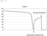
- FIG. 1 is a graph showing a change in voltage when a lithium ion battery is discharged, left unattended, and then discharged again.
- a state of charge (SOC) of a battery such as a lithium-ion battery being 0 or less (2.5V to 3V)
- SOC state of charge
- a phenomenon in which terminal voltage is recovered may be confirmed, and in this time, when the discharging is performed again, it may be confirmed that a significant amount of initial discharge current is generated.
- lithium (Li) that is not discharged exists in a negative electrode through normal discharge.
- the present inventors have found that in a case in which a voltage opposite to the discharge from a point at which battery voltage appears at 0V during discharging until now, that is, reverse voltage, is applied, lithium remaining on the negative electrode may be moved to a positive electrode more quickly, and when this condition continues for a certain period of time, this develops into an internal short circuit and the terminal voltage of the battery becomes unrecoverable, and have completed the present invention.
- a discharge method of a battery including: a first discharging step of discharging a battery by connecting the battery and a power converter and applying voltage thereto; and a second discharging step of discharging the battery by applying a reverse voltage of the voltage of the first discharging step, after the first discharging step.
- the first discharging step may be performed until the state of charge (SOC) of the battery becomes 0.
- SOC state of charge
- a fast discharge rate may be secured by setting a maximum value within the rated current and an allowable temperature range according to the battery standard. Accordingly, in the first discharging step, the applied voltage may be 2.5 to 4V, the current may be 0.3C or more, and the temperature of the battery may be 60°C or lower.
- a step of discharging the battery until the terminal voltage becomes 0V may be included.
- a value when the terminal voltage of the battery is divided by an internal impedance of a power converter that is, a magnitude of a short circuit current is voltage decreased to a lower limit of an operating current of a power semiconductor used in the power converter
- an effective operating range of the power converter is designed to be in a 3V region based on a unit cell, so that operating near 0V is not only inefficient but also acts as a factor in slowing down the discharge rate.
- the present invention is not particularly limited, but the short circuit operation mode may be adjusted to minimize the sum of the short circuit operation time and the reverse voltage operation time depending on the type of battery, and is preferably performed for 1 minute or less.
- the power converter may operate in an energy regeneration mode, through which it may be possible to recover and recycle energy remaining in the battery.
- a second discharging step may be performed in which the battery is discharged by applying reverse voltage of the first discharging step.
- the voltage applied in the second discharging step is, preferably, 0 to 3V
- the current is, preferably, 0.05 to 1C, which may be set to operate in response to changes in internal resistance. More specifically, the current may be quickly increased to a level of 1C by applying the reverse voltage, and the terminal voltage of the battery may increase to a level of 2 to 3V in a negative direction, and then, when the current is maintained, the terminal voltage may be in a decreased shape again, and after passing an inflection point representing maximum voltage, the reverse voltage may be reduced to maintain a current amount at a level of 0.
- the second discharging step may be performed a plurality of times. Depending on the operation based on reverse voltage application, after the current becomes 0, the battery voltage may gradually approach 0V, but a secondary reverse voltage operation may be repeatedly performed in the same manner as a primary reverse voltage operation, thus stabilizing voltage fluctuations.
- the second discharging step may be performed until the short circuit resistance is 30 to 60 mQ.
- a size of maximum negative voltage appearing as the second discharging step advances may tend to gradually decrease, which is due to the short circuit resistance decreasing as the internal short circuit progresses. Accordingly, the determination to terminate the reverse voltage operation may be performed when the short circuit resistance obtained by dividing the maximum negative voltage during the repeated operation of the second discharging step by the reverse current is 30 to 60 mS2.
- the second discharging step operation time may be finely adjusted through experimentation to minimize the sum of a short circuit operation duration and reverse voltage operation time depending on the type of secondary battery, and the operation may usually be repeated within 1 minute.
- the power converter may independently distribute energy to a plurality of batteries being discharged.
- FIG. 2 illustrates a battery discharge device according to an embodiment of the present invention, and according to another aspect of the present invention, provided is a battery discharge device including: a power converter including an AC-DC power supply device and a DC-DC power supply device; and a controller.
- the AC-DC power supply device may control direct current power used jointly, such as factory power, and may reverse-feed electrical energy obtained when a lower DC-DC power supply device performs a battery discharge function to a commonly used power source.
- the total amount of the reverse-fed electrical energy may be defined as a maximum value by adding and calculating the total amount of discharge energy from each battery in the lower DC-DC power supply device, and a capacity of the AC-DC power supply device may be designed to operate with the total amount.
- the AC-DC power supply device may perform the function of maintaining commonly used DC voltage to supply sufficient energy when the DC-DC power supply device applies a reverse voltage to the secondary battery.
- the DC-DC power supply is not particularly limited and may be composed of a combination of a unipolar Buck-Boost converter and a mechanical switch capable of reversing output polarity, or may be composed of a bipolar singlephase PWM converter.
- the controller may serve to control a discharge process of the secondary battery, including the first discharging step of discharging the secondary battery by connecting the battery and the power converter and applying voltage thereto, and the second discharging step of discharging the secondary battery by applying voltage (reverse voltage) opposite to the voltage of the first discharging step.
- the controller may build a database of a discharge control pattern of the power converter according to the electric vehicle model and battery type, thus allowing a driver to select and drive on-site or remotely, and the database may be configured to be remotely updateable.
- S1 in a case of S/W 1 closed, S/W 2 closed, S/W 3 closed, and S/W 4 open, S1 is prevented from operating, and a switching operation of S2 allows the energy of the secondary battery to be transmitted to a DC power capacitor of an AC-DC converter, and the AC-DC converter transmits energy transferred from the battery to a DC-DC converter.
Landscapes
- Engineering & Computer Science (AREA)
- Power Engineering (AREA)
- Manufacturing & Machinery (AREA)
- Chemical & Material Sciences (AREA)
- Chemical Kinetics & Catalysis (AREA)
- Electrochemistry (AREA)
- General Chemical & Material Sciences (AREA)
- Secondary Cells (AREA)
- Charge And Discharge Circuits For Batteries Or The Like (AREA)
Abstract
Description
- The present invention relates to a discharge method of a battery.
- A process of recovering expensive metals used in batteries such as small lithium-ion batteries used in mobile and home appliances mainly uses methods such as crushing and grinding after discharging, sintering, wet smelting after a separation process, and in some processes, a discharge process is omitted and a dry melting and separation process is used commercially. The most common discharging method in the wet process is a natural discharging method by immersing a secondary battery in an aqueous chemical solution manufactured for the purpose of completely discharging the secondary battery.
- Meanwhile, a secondary battery for a vehicle is manufactured to use a relatively higher voltage (currently around 800V) than the voltage of a single battery, 4V, by connecting several secondary batteries in series and in parallel to ensure efficiency in driving the vehicle, and is structurally and robustly assembled for safety.
- When a secondary battery assembly for a vehicle is subjected to natural discharge treatment by immersing the secondary battery assembly in an aqueous chemical solution, the difficulty of the process of dismantling unnecessary components increases to increase a recovery rate of a desired metal, and thus, this case mainly uses a method in which after discharging energy contained in the secondary battery to a level of 0 using an electrical load, the secondary battery assembly is disassembled manually, and is immersed in an aqueous chemical solution to discharge the secondary battery naturally.
- In this case, after a certain amount of time has passed after discharging the secondary battery to normal energy on a level of "0," output voltage of a normal battery is recovered from 0V to 2.5V, and an 800V automotive battery maintains voltage of about 500V, which may threaten safety and still cause a difficult manual task.
- The present invention is developed in consideration of the circumstances described above, and an aspect of the present invention is to provide a discharge method of a battery in which electrical energy of a battery may be recovered and recycled, and an electrically safe state may be secured in a subsequent disassembly process by putting the battery in a completely discharged state in which normal operation is impossible.
- According to an aspect of the present invention, provided is a discharge method of a battery including: a first discharging step of discharging a battery by connecting the battery and a power converter and applying voltage thereto; and a second discharging step of discharging the battery by applying a reverse voltage of the voltage of the first discharging step, after the first discharging step.
- The first discharging step may be performed until a state of charge (SOC) of the battery becomes 0.
- The discharge method may include a step of discharging the battery until a terminal voltage of the battery becomes 0V after a state of charge (SOC) of the battery becomes 0.
- In the step of discharging the battery until the terminal voltage of the battery reaches 0V, a short circuit may be generated.
- In the first discharging step, applied voltage may be 2.5 to 4 V, and a current may be 0.3 C or more.
- In the first discharging step, a battery temperature may be 60°C or lower.
- In the first discharging step, a power converter may operate in an energy regeneration mode.
- Voltage applied in the second discharging step may be 0 to 3V, and a current may be 0.05 to 1C.
- The second discharging step may be performed a plurality of times.
- The second discharging step may be terminated when short circuit resistance is 30 to 60 mQ.
- In the second discharging step, a power converter may independently distribute energy to a plurality of discharged batteries.
- According to an aspect of the present invention, electrical energy of a battery may be recovered and recycled, and an electrically safe state may be secured in a subsequent disassembly process by putting the battery in a completely discharged state in which normal operation is impossible.
-
-
FIG. 1 is a graph showing a change in voltage when a lithium ion battery is discharged, left unattended, and then discharged again. -
FIG. 2 illustrates a battery discharge device according to an embodiment of the present invention. -
FIG. 3 illustrates an example of discharging a battery by configuring a DC-DC converter as a Buck-Boost power converter according to an embodiment of the present invention. Best Mode for Invention - Hereinafter, preferred embodiments of the present invention will be described with reference to various embodiments. However, embodiments of the present invention may be modified into various different forms, and the scope of the present invention is not limited to the embodiments described below.
- The present invention relates to a discharge method of a battery.
-
FIG. 1 is a graph showing a change in voltage when a lithium ion battery is discharged, left unattended, and then discharged again. Referring toFIG. 1 , generally, after the lithium ion battery is discharged by 0V with a value of a state of charge (SOC) of a battery such as a lithium-ion battery being 0 or less (2.5V to 3V), when the lithium ion battery is left for several minutes to several tens of minutes, a phenomenon in which terminal voltage is recovered may be confirmed, and in this time, when the discharging is performed again, it may be confirmed that a significant amount of initial discharge current is generated. From this, it may be seen that a significant amount of lithium (Li) that is not discharged exists in a negative electrode through normal discharge. After painstaking research to solve the problem caused by the presence of lithium remaining in the negative electrode, the present inventors have found that in a case in which a voltage opposite to the discharge from a point at which battery voltage appears at 0V during discharging until now, that is, reverse voltage, is applied, lithium remaining on the negative electrode may be moved to a positive electrode more quickly, and when this condition continues for a certain period of time, this develops into an internal short circuit and the terminal voltage of the battery becomes unrecoverable, and have completed the present invention. - According to an aspect of the present invention, provided is a discharge method of a battery including: a first discharging step of discharging a battery by connecting the battery and a power converter and applying voltage thereto; and a second discharging step of discharging the battery by applying a reverse voltage of the voltage of the first discharging step, after the first discharging step.
- The first discharging step may be performed until the state of charge (SOC) of the battery becomes 0. In a discharge section of the first discharging step, for a discharge rate, a fast discharge rate may be secured by setting a maximum value within the rated current and an allowable temperature range according to the battery standard. Accordingly, in the first discharging step, the applied voltage may be 2.5 to 4V, the current may be 0.3C or more, and the temperature of the battery may be 60°C or lower.
- As described above, after the state of charge (SOC) of the battery becomes 0, a step of discharging the battery until the terminal voltage becomes 0V may be included. Specifically, in a case in which a value when the terminal voltage of the battery is divided by an internal impedance of a power converter, that is, a magnitude of a short circuit current is voltage decreased to a lower limit of an operating current of a power semiconductor used in the power converter, it may be desirable to approach 0V by switching from an operation mode for energy recovery to a short circuit operation mode or reverse voltage. This is because an effective operating range of the power converter is designed to be in a 3V region based on a unit cell, so that operating near 0V is not only inefficient but also acts as a factor in slowing down the discharge rate. The present invention is not particularly limited, but the short circuit operation mode may be adjusted to minimize the sum of the short circuit operation time and the reverse voltage operation time depending on the type of battery, and is preferably performed for 1 minute or less.
- Furthermore, in the first discharging step, the power converter may operate in an energy regeneration mode, through which it may be possible to recover and recycle energy remaining in the battery.
- After the first discharging step, a second discharging step may be performed in which the battery is discharged by applying reverse voltage of the first discharging step.
- In this case, the voltage applied in the second discharging step is, preferably, 0 to 3V, and the current is, preferably, 0.05 to 1C, which may be set to operate in response to changes in internal resistance. More specifically, the current may be quickly increased to a level of 1C by applying the reverse voltage, and the terminal voltage of the battery may increase to a level of 2 to 3V in a negative direction, and then, when the current is maintained, the terminal voltage may be in a decreased shape again, and after passing an inflection point representing maximum voltage, the reverse voltage may be reduced to maintain a current amount at a level of 0.
- The second discharging step may be performed a plurality of times. Depending on the operation based on reverse voltage application, after the current becomes 0, the battery voltage may gradually approach 0V, but a secondary reverse voltage operation may be repeatedly performed in the same manner as a primary reverse voltage operation, thus stabilizing voltage fluctuations.
- The second discharging step may be performed until the short circuit resistance is 30 to 60 mQ. In more detail, a size of maximum negative voltage appearing as the second discharging step advances may tend to gradually decrease, which is due to the short circuit resistance decreasing as the internal short circuit progresses. Accordingly, the determination to terminate the reverse voltage operation may be performed when the short circuit resistance obtained by dividing the maximum negative voltage during the repeated operation of the second discharging step by the reverse current is 30 to 60 mS2.
- The second discharging step operation time may be finely adjusted through experimentation to minimize the sum of a short circuit operation duration and reverse voltage operation time depending on the type of secondary battery, and the operation may usually be repeated within 1 minute.
- Additionally, in the second discharging step, the power converter may independently distribute energy to a plurality of batteries being discharged.
- Meanwhile,
FIG. 2 illustrates a battery discharge device according to an embodiment of the present invention, and according to another aspect of the present invention, provided is a battery discharge device including: a power converter including an AC-DC power supply device and a DC-DC power supply device; and a controller. - The AC-DC power supply device may control direct current power used jointly, such as factory power, and may reverse-feed electrical energy obtained when a lower DC-DC power supply device performs a battery discharge function to a commonly used power source. The total amount of the reverse-fed electrical energy may be defined as a maximum value by adding and calculating the total amount of discharge energy from each battery in the lower DC-DC power supply device, and a capacity of the AC-DC power supply device may be designed to operate with the total amount.
- Accordingly, the AC-DC power supply device may perform the function of maintaining commonly used DC voltage to supply sufficient energy when the DC-DC power supply device applies a reverse voltage to the secondary battery.
- The DC-DC power supply is not particularly limited and may be composed of a combination of a unipolar Buck-Boost converter and a mechanical switch capable of reversing output polarity, or may be composed of a bipolar singlephase PWM converter.
- Meanwhile, the controller may serve to control a discharge process of the secondary battery, including the first discharging step of discharging the secondary battery by connecting the battery and the power converter and applying voltage thereto, and the second discharging step of discharging the secondary battery by applying voltage (reverse voltage) opposite to the voltage of the first discharging step. The controller may build a database of a discharge control pattern of the power converter according to the electric vehicle model and battery type, thus allowing a driver to select and drive on-site or remotely, and the database may be configured to be remotely updateable.
- Hereinafter, the present invention will be described in more detail through examples. The following examples are intended to illustrate the present invention in more detail and are not intended to limit the present invention thereto.
- Referring to
FIG. 3 , in the first discharging step, in a case of S/W 1 closed, S/W 2 closed, S/W 3 closed, and S/W 4 open, S1 is prevented from operating, and a switching operation of S2 allows the energy of the secondary battery to be transmitted to a DC power capacitor of an AC-DC converter, and the AC-DC converter transmits energy transferred from the battery to a DC-DC converter. - Then, when the battery voltage drops to 0 V after 2.5 V due to sufficient discharge, a short circuit discharge is performed by continuing an on-state of S2 at the time when it is determined that the short circuit discharge is possible in consideration of the internal impedance of the converter. In this case, S1 does not operate.
- Then, by closing S/W 4 and opening S/W 3, a mode is switched to a reverse voltage operation mode, and S2 is turned off and the reverse voltage operation mode is executed using S1, thereby completely discharging the battery.
- Although the embodiment of the present invention has been described in detail above, the scope of the present invention is not limited thereto. Therefore, those of ordinary skill in the art may make various modifications and changes without departing from the technical concept of the present invention described in the claims.
Claims (11)
- A discharge method of a battery, comprising:a first discharging step of discharging a battery by connecting the battery and a power converter and applying voltage thereto; anda second discharging step of discharging the battery by applying a reverse voltage of the voltage of the first discharging step, after the first discharging step.
- The discharge method of a battery of claim 1, wherein the first discharging step is performed until a state of charge (SOC) of the battery becomes 0.
- The discharge method of a battery of claim 1, comprising:
a step of discharging the battery until a terminal voltage of the battery becomes 0V after a state of charge (SOC) of the battery becomes 0. - The discharge method of a battery of claim 3, wherein in the step of discharging the battery until the terminal voltage of the battery reaches 0V, a short circuit is generated.
- The discharge method of a battery of claim 1, wherein in the first discharging step, applied voltage is 2.5 to 4 V, and a current is 0.3 C or more.
- The discharge method of a battery of claim 1, wherein in the first discharging step, a battery temperature is 60°C or lower.
- The discharge method of a battery of claim 1, wherein in the first discharging step, a power converter operates in an energy regeneration mode.
- The discharge method of a battery of claim 1, wherein in the second discharging step, applied voltage is 0 to 3V, and a current is 0.05 to 1C.
- The discharge method of a battery of claim 1, wherein the second discharging step is performed a plurality of times.
- The discharge method of a battery of claim 1, wherein the second discharging step is terminated when short circuit resistance is 30 to 60 mQ.
- The discharge method of a battery of claim 1, wherein in the second discharging step, a power converter independently distributes energy to a plurality of discharged batteries.
Applications Claiming Priority (2)
| Application Number | Priority Date | Filing Date | Title |
|---|---|---|---|
| KR1020210182179A KR102812644B1 (en) | 2021-12-17 | 2021-12-17 | Discharge method of Battery |
| PCT/KR2022/020658 WO2023113568A1 (en) | 2021-12-17 | 2022-12-16 | Discharge method of battery |
Publications (2)
| Publication Number | Publication Date |
|---|---|
| EP4451421A1 true EP4451421A1 (en) | 2024-10-23 |
| EP4451421A4 EP4451421A4 (en) | 2025-04-02 |
Family
ID=86773188
Family Applications (1)
| Application Number | Title | Priority Date | Filing Date |
|---|---|---|---|
| EP22908033.8A Pending EP4451421A4 (en) | 2021-12-17 | 2022-12-16 | Discharge method of battery |
Country Status (6)
| Country | Link |
|---|---|
| US (1) | US20250023127A1 (en) |
| EP (1) | EP4451421A4 (en) |
| JP (1) | JP7849077B2 (en) |
| KR (1) | KR102812644B1 (en) |
| CN (1) | CN118435423A (en) |
| WO (1) | WO2023113568A1 (en) |
Families Citing this family (5)
| Publication number | Priority date | Publication date | Assignee | Title |
|---|---|---|---|---|
| SE2351001A1 (en) * | 2023-08-28 | 2025-03-01 | Northvolt Revolt Ab | Processes and systems for discharge |
| KR20250033449A (en) * | 2023-08-29 | 2025-03-10 | 현대자동차주식회사 | Apparatus for managing a battery, system and method thereof |
| KR20250137242A (en) | 2024-03-11 | 2025-09-18 | (주)오디에이테크놀로지 | Battery discharge device for recycling waste batteries |
| KR20250137241A (en) | 2024-03-11 | 2025-09-18 | (주)오디에이테크놀로지 | Battery discharge device for recycling waste batteries |
| CN119518142B (en) * | 2025-01-20 | 2025-05-02 | 湖南大学 | A method and system for deep discharge safety passivation of waste power batteries |
Family Cites Families (6)
| Publication number | Priority date | Publication date | Assignee | Title |
|---|---|---|---|---|
| JPH06245392A (en) * | 1993-02-17 | 1994-09-02 | Meidensha Corp | Converter for regulating power system energy |
| KR200175881Y1 (en) * | 1996-05-06 | 2000-04-15 | 강평원 | Discharging apparatus for battery |
| KR100349723B1 (en) * | 1999-10-12 | 2002-08-22 | 서통테크놀로지주식회사 | a device for discharging a lithum ion battery |
| JP5156112B2 (en) * | 2011-07-28 | 2013-03-06 | 三菱重工業株式会社 | Battery system |
| JP6157880B2 (en) * | 2013-03-04 | 2017-07-05 | 株式会社東芝 | Secondary battery system having a plurality of batteries and charge / discharge power distribution method |
| KR102245581B1 (en) * | 2019-06-07 | 2021-04-29 | 강재봉 | Regenerative battery test device with zero volt complete discharge, Discharge method of that equipment |
-
2021
- 2021-12-17 KR KR1020210182179A patent/KR102812644B1/en active Active
-
2022
- 2022-12-16 US US18/710,782 patent/US20250023127A1/en active Pending
- 2022-12-16 CN CN202280082537.XA patent/CN118435423A/en active Pending
- 2022-12-16 EP EP22908033.8A patent/EP4451421A4/en active Pending
- 2022-12-16 WO PCT/KR2022/020658 patent/WO2023113568A1/en not_active Ceased
- 2022-12-16 JP JP2024530036A patent/JP7849077B2/en active Active
Also Published As
| Publication number | Publication date |
|---|---|
| KR102812644B1 (en) | 2025-05-27 |
| EP4451421A4 (en) | 2025-04-02 |
| JP7849077B2 (en) | 2026-04-21 |
| US20250023127A1 (en) | 2025-01-16 |
| JP2024541453A (en) | 2024-11-08 |
| CN118435423A (en) | 2024-08-02 |
| WO2023113568A1 (en) | 2023-06-22 |
| KR20230093137A (en) | 2023-06-27 |
Similar Documents
| Publication | Publication Date | Title |
|---|---|---|
| EP4451421A1 (en) | Discharge method of battery | |
| TWI594540B (en) | Power storage system and power system | |
| US7928698B2 (en) | Battery charging apparatus and method | |
| MXPA97003852A (en) | Accumulated loading and conditioning | |
| JPH0419673B2 (en) | ||
| US9413037B2 (en) | Cell capacity adjusting device | |
| EP3726699A1 (en) | Starting power supply device and method for mobile charging vehicle | |
| JP2018026209A (en) | Nickel metal hydride battery charging method and charging system | |
| CN114189007A (en) | Vehicle-mounted charger working mode switching control method and device and vehicle-mounted charger | |
| JP2009124795A (en) | Charging method and apparatus | |
| WO2020241215A1 (en) | Backup power supply device for vehicle | |
| KR101604419B1 (en) | Charging and Discharging Testing Device | |
| JP6885688B2 (en) | How to regenerate nickel metal hydride batteries | |
| CN110854960A (en) | Frequency change pulse charging method and system for lead-acid battery | |
| CN218733294U (en) | Ultra-micro energy conversion circuit and energy storage device | |
| JP2003189498A (en) | Charging method and charger of secondary battery | |
| CN215681833U (en) | Multi-battery management system and service robot | |
| US12447841B2 (en) | Electrified vehicle | |
| CN207573077U (en) | Starting power supply device for mobile charging car | |
| KR102340096B1 (en) | Power supply for motorcycle start motor | |
| JP2016005362A (en) | Secondary battery system and control method for secondary battery system | |
| CN218216698U (en) | Energy storage device of wind turbine generator | |
| CN120237761A (en) | Charging method, energy storage power supply, control device and medium | |
| KR20250125013A (en) | Performance Restoration Method for Lead Cells Using a Waste Lead Cell Performance Restoration Device | |
| KR200140944Y1 (en) | Overcharging protection apparatus of a battery |
Legal Events
| Date | Code | Title | Description |
|---|---|---|---|
| STAA | Information on the status of an ep patent application or granted ep patent |
Free format text: STATUS: THE INTERNATIONAL PUBLICATION HAS BEEN MADE |
|
| PUAI | Public reference made under article 153(3) epc to a published international application that has entered the european phase |
Free format text: ORIGINAL CODE: 0009012 |
|
| STAA | Information on the status of an ep patent application or granted ep patent |
Free format text: STATUS: REQUEST FOR EXAMINATION WAS MADE |
|
| 17P | Request for examination filed |
Effective date: 20240704 |
|
| AK | Designated contracting states |
Kind code of ref document: A1 Designated state(s): AL AT BE BG CH CY CZ DE DK EE ES FI FR GB GR HR HU IE IS IT LI LT LU LV MC ME MK MT NL NO PL PT RO RS SE SI SK SM TR |
|
| REG | Reference to a national code |
Ref country code: DE Ref legal event code: R079 Free format text: PREVIOUS MAIN CLASS: H01M0010440000 Ipc: H02J0007000000 |
|
| DAV | Request for validation of the european patent (deleted) | ||
| DAX | Request for extension of the european patent (deleted) | ||
| A4 | Supplementary search report drawn up and despatched |
Effective date: 20250227 |
|
| RIC1 | Information provided on ipc code assigned before grant |
Ipc: H02J 7/00 20060101AFI20250221BHEP |