EP4451399A1 - Lithium secondary battery - Google Patents
Lithium secondary battery Download PDFInfo
- Publication number
- EP4451399A1 EP4451399A1 EP22905494.5A EP22905494A EP4451399A1 EP 4451399 A1 EP4451399 A1 EP 4451399A1 EP 22905494 A EP22905494 A EP 22905494A EP 4451399 A1 EP4451399 A1 EP 4451399A1
- Authority
- EP
- European Patent Office
- Prior art keywords
- layer
- lithium
- secondary battery
- solid electrolyte
- ion
- Prior art date
- Legal status (The legal status is an assumption and is not a legal conclusion. Google has not performed a legal analysis and makes no representation as to the accuracy of the status listed.)
- Pending
Links
- 229910052744 lithium Inorganic materials 0.000 title claims abstract description 103
- WHXSMMKQMYFTQS-UHFFFAOYSA-N Lithium Chemical compound [Li] WHXSMMKQMYFTQS-UHFFFAOYSA-N 0.000 title claims abstract description 75
- 239000007784 solid electrolyte Substances 0.000 claims abstract description 102
- 150000002500 ions Chemical class 0.000 claims abstract description 69
- 239000007774 positive electrode material Substances 0.000 claims abstract description 62
- 238000006243 chemical reaction Methods 0.000 claims abstract description 56
- HBBGRARXTFLTSG-UHFFFAOYSA-N Lithium ion Chemical compound [Li+] HBBGRARXTFLTSG-UHFFFAOYSA-N 0.000 claims abstract description 44
- 229910001416 lithium ion Inorganic materials 0.000 claims abstract description 44
- 239000000463 material Substances 0.000 claims description 51
- 239000002105 nanoparticle Substances 0.000 claims description 51
- 239000000470 constituent Substances 0.000 claims description 25
- 239000002245 particle Substances 0.000 claims description 15
- 229910052751 metal Inorganic materials 0.000 claims description 14
- 239000002184 metal Substances 0.000 claims description 13
- OKTJSMMVPCPJKN-UHFFFAOYSA-N Carbon Chemical compound [C] OKTJSMMVPCPJKN-UHFFFAOYSA-N 0.000 claims description 10
- 229910052782 aluminium Inorganic materials 0.000 claims description 7
- 229910052799 carbon Inorganic materials 0.000 claims description 7
- 229910052710 silicon Inorganic materials 0.000 claims description 6
- 229910052718 tin Inorganic materials 0.000 claims description 6
- XUIMIQQOPSSXEZ-UHFFFAOYSA-N Silicon Chemical compound [Si] XUIMIQQOPSSXEZ-UHFFFAOYSA-N 0.000 claims description 5
- XAGFODPZIPBFFR-UHFFFAOYSA-N aluminium Chemical compound [Al] XAGFODPZIPBFFR-UHFFFAOYSA-N 0.000 claims description 5
- 239000010703 silicon Substances 0.000 claims description 5
- KDLHZDBZIXYQEI-UHFFFAOYSA-N Palladium Chemical compound [Pd] KDLHZDBZIXYQEI-UHFFFAOYSA-N 0.000 claims description 4
- ATJFFYVFTNAWJD-UHFFFAOYSA-N Tin Chemical compound [Sn] ATJFFYVFTNAWJD-UHFFFAOYSA-N 0.000 claims description 4
- 150000004767 nitrides Chemical class 0.000 claims description 4
- BASFCYQUMIYNBI-UHFFFAOYSA-N platinum Chemical compound [Pt] BASFCYQUMIYNBI-UHFFFAOYSA-N 0.000 claims description 4
- BQCADISMDOOEFD-UHFFFAOYSA-N Silver Chemical compound [Ag] BQCADISMDOOEFD-UHFFFAOYSA-N 0.000 claims description 3
- 229910052797 bismuth Inorganic materials 0.000 claims description 3
- JCXGWMGPZLAOME-UHFFFAOYSA-N bismuth atom Chemical compound [Bi] JCXGWMGPZLAOME-UHFFFAOYSA-N 0.000 claims description 3
- 229910052709 silver Inorganic materials 0.000 claims description 3
- 239000004332 silver Substances 0.000 claims description 3
- 229910052725 zinc Inorganic materials 0.000 claims description 3
- 239000011701 zinc Substances 0.000 claims description 3
- HCHKCACWOHOZIP-UHFFFAOYSA-N Zinc Chemical compound [Zn] HCHKCACWOHOZIP-UHFFFAOYSA-N 0.000 claims description 2
- PCHJSUWPFVWCPO-UHFFFAOYSA-N gold Chemical compound [Au] PCHJSUWPFVWCPO-UHFFFAOYSA-N 0.000 claims description 2
- 229910052737 gold Inorganic materials 0.000 claims description 2
- 239000010931 gold Substances 0.000 claims description 2
- 229910052763 palladium Inorganic materials 0.000 claims description 2
- 229910052697 platinum Inorganic materials 0.000 claims description 2
- 210000001787 dendrite Anatomy 0.000 abstract description 17
- 238000001556 precipitation Methods 0.000 abstract description 9
- 239000010410 layer Substances 0.000 description 308
- PNEYBMLMFCGWSK-UHFFFAOYSA-N aluminium oxide Inorganic materials [O-2].[O-2].[O-2].[Al+3].[Al+3] PNEYBMLMFCGWSK-UHFFFAOYSA-N 0.000 description 32
- 239000006229 carbon black Substances 0.000 description 31
- 238000011156 evaluation Methods 0.000 description 27
- 210000004027 cell Anatomy 0.000 description 24
- 238000000034 method Methods 0.000 description 23
- 239000007773 negative electrode material Substances 0.000 description 20
- 239000011888 foil Substances 0.000 description 13
- 239000002002 slurry Substances 0.000 description 12
- 239000002904 solvent Substances 0.000 description 10
- 230000000052 comparative effect Effects 0.000 description 9
- 230000008569 process Effects 0.000 description 9
- 239000011230 binding agent Substances 0.000 description 7
- 239000011347 resin Substances 0.000 description 7
- 229920005989 resin Polymers 0.000 description 7
- 239000007787 solid Substances 0.000 description 7
- 239000002203 sulfidic glass Substances 0.000 description 7
- 239000011149 active material Substances 0.000 description 6
- 150000001875 compounds Chemical class 0.000 description 6
- 238000000151 deposition Methods 0.000 description 6
- 238000003475 lamination Methods 0.000 description 6
- 230000000694 effects Effects 0.000 description 5
- 239000011135 tin Substances 0.000 description 5
- 229910009297 Li2S-P2S5 Inorganic materials 0.000 description 4
- 229910009228 Li2S—P2S5 Inorganic materials 0.000 description 4
- VYPSYNLAJGMNEJ-UHFFFAOYSA-N Silicium dioxide Chemical compound O=[Si]=O VYPSYNLAJGMNEJ-UHFFFAOYSA-N 0.000 description 4
- 239000010419 fine particle Substances 0.000 description 4
- 230000002706 hydrostatic effect Effects 0.000 description 4
- 239000005001 laminate film Substances 0.000 description 4
- AUHZEENZYGFFBQ-UHFFFAOYSA-N mesitylene Substances CC1=CC(C)=CC(C)=C1 AUHZEENZYGFFBQ-UHFFFAOYSA-N 0.000 description 4
- 125000001827 mesitylenyl group Chemical group [H]C1=C(C(*)=C(C([H])=C1C([H])([H])[H])C([H])([H])[H])C([H])([H])[H] 0.000 description 4
- 238000003825 pressing Methods 0.000 description 4
- 238000004544 sputter deposition Methods 0.000 description 4
- 229920003048 styrene butadiene rubber Polymers 0.000 description 4
- 238000000354 decomposition reaction Methods 0.000 description 3
- 230000007423 decrease Effects 0.000 description 3
- 238000007599 discharging Methods 0.000 description 3
- 238000001035 drying Methods 0.000 description 3
- 230000002093 peripheral effect Effects 0.000 description 3
- 230000002829 reductive effect Effects 0.000 description 3
- 239000000126 substance Substances 0.000 description 3
- 229910018539 Ni—Mn—Co Inorganic materials 0.000 description 2
- 239000006230 acetylene black Substances 0.000 description 2
- 239000011248 coating agent Substances 0.000 description 2
- 238000000576 coating method Methods 0.000 description 2
- 239000002131 composite material Substances 0.000 description 2
- 229920001971 elastomer Polymers 0.000 description 2
- -1 lithium transition metal Chemical class 0.000 description 2
- TWNQGVIAIRXVLR-UHFFFAOYSA-N oxo(oxoalumanyloxy)alumane Chemical compound O=[Al]O[Al]=O TWNQGVIAIRXVLR-UHFFFAOYSA-N 0.000 description 2
- 229910052698 phosphorus Inorganic materials 0.000 description 2
- 239000011435 rock Substances 0.000 description 2
- 239000005060 rubber Substances 0.000 description 2
- 239000011734 sodium Substances 0.000 description 2
- 229910052719 titanium Inorganic materials 0.000 description 2
- 239000010936 titanium Substances 0.000 description 2
- 238000003466 welding Methods 0.000 description 2
- 229910052726 zirconium Inorganic materials 0.000 description 2
- ZOXJGFHDIHLPTG-UHFFFAOYSA-N Boron Chemical compound [B] ZOXJGFHDIHLPTG-UHFFFAOYSA-N 0.000 description 1
- XMWRBQBLMFGWIX-UHFFFAOYSA-N C60 fullerene Chemical compound C12=C3C(C4=C56)=C7C8=C5C5=C9C%10=C6C6=C4C1=C1C4=C6C6=C%10C%10=C9C9=C%11C5=C8C5=C8C7=C3C3=C7C2=C1C1=C2C4=C6C4=C%10C6=C9C9=C%11C5=C5C8=C3C3=C7C1=C1C2=C4C6=C2C9=C5C3=C12 XMWRBQBLMFGWIX-UHFFFAOYSA-N 0.000 description 1
- OYPRJOBELJOOCE-UHFFFAOYSA-N Calcium Chemical compound [Ca] OYPRJOBELJOOCE-UHFFFAOYSA-N 0.000 description 1
- DGAQECJNVWCQMB-PUAWFVPOSA-M Ilexoside XXIX Chemical compound C[C@@H]1CC[C@@]2(CC[C@@]3(C(=CC[C@H]4[C@]3(CC[C@@H]5[C@@]4(CC[C@@H](C5(C)C)OS(=O)(=O)[O-])C)C)[C@@H]2[C@]1(C)O)C)C(=O)O[C@H]6[C@@H]([C@H]([C@@H]([C@H](O6)CO)O)O)O.[Na+] DGAQECJNVWCQMB-PUAWFVPOSA-M 0.000 description 1
- 229910008039 Li-M-O Inorganic materials 0.000 description 1
- 229910009731 Li2FeSiO4 Inorganic materials 0.000 description 1
- 229910010142 Li2MnSiO4 Inorganic materials 0.000 description 1
- 229910002986 Li4Ti5O12 Inorganic materials 0.000 description 1
- 229910032387 LiCoO2 Inorganic materials 0.000 description 1
- 229910052493 LiFePO4 Inorganic materials 0.000 description 1
- 229910002993 LiMnO2 Inorganic materials 0.000 description 1
- 229910000668 LiMnPO4 Inorganic materials 0.000 description 1
- 229910002099 LiNi0.5Mn1.5O4 Inorganic materials 0.000 description 1
- 229910015965 LiNi0.8Mn0.1Co0.1O2 Inorganic materials 0.000 description 1
- 229910003005 LiNiO2 Inorganic materials 0.000 description 1
- 229910012981 LiVO2 Inorganic materials 0.000 description 1
- 229910002097 Lithium manganese(III,IV) oxide Inorganic materials 0.000 description 1
- FYYHWMGAXLPEAU-UHFFFAOYSA-N Magnesium Chemical compound [Mg] FYYHWMGAXLPEAU-UHFFFAOYSA-N 0.000 description 1
- ZLMJMSJWJFRBEC-UHFFFAOYSA-N Potassium Chemical compound [K] ZLMJMSJWJFRBEC-UHFFFAOYSA-N 0.000 description 1
- UCKMPCXJQFINFW-UHFFFAOYSA-N Sulphide Chemical compound [S-2] UCKMPCXJQFINFW-UHFFFAOYSA-N 0.000 description 1
- 229910010252 TiO3 Inorganic materials 0.000 description 1
- RTAQQCXQSZGOHL-UHFFFAOYSA-N Titanium Chemical compound [Ti] RTAQQCXQSZGOHL-UHFFFAOYSA-N 0.000 description 1
- QCWXUUIWCKQGHC-UHFFFAOYSA-N Zirconium Chemical compound [Zr] QCWXUUIWCKQGHC-UHFFFAOYSA-N 0.000 description 1
- 229910045601 alloy Inorganic materials 0.000 description 1
- 239000000956 alloy Substances 0.000 description 1
- 229910003481 amorphous carbon Inorganic materials 0.000 description 1
- 229910052787 antimony Inorganic materials 0.000 description 1
- 230000004888 barrier function Effects 0.000 description 1
- 230000000903 blocking effect Effects 0.000 description 1
- 229910052796 boron Inorganic materials 0.000 description 1
- 229910052794 bromium Inorganic materials 0.000 description 1
- 229910052791 calcium Inorganic materials 0.000 description 1
- 239000011575 calcium Substances 0.000 description 1
- 239000002134 carbon nanofiber Substances 0.000 description 1
- 239000002041 carbon nanotube Substances 0.000 description 1
- 229910021393 carbon nanotube Inorganic materials 0.000 description 1
- 230000008859 change Effects 0.000 description 1
- 229910052801 chlorine Inorganic materials 0.000 description 1
- 229910052804 chromium Inorganic materials 0.000 description 1
- 229910017052 cobalt Inorganic materials 0.000 description 1
- 239000010941 cobalt Substances 0.000 description 1
- GUTLYIVDDKVIGB-UHFFFAOYSA-N cobalt atom Chemical compound [Co] GUTLYIVDDKVIGB-UHFFFAOYSA-N 0.000 description 1
- 239000011231 conductive filler Substances 0.000 description 1
- 229920001940 conductive polymer Polymers 0.000 description 1
- 230000001186 cumulative effect Effects 0.000 description 1
- 230000003247 decreasing effect Effects 0.000 description 1
- 230000006866 deterioration Effects 0.000 description 1
- 239000007772 electrode material Substances 0.000 description 1
- 239000003792 electrolyte Substances 0.000 description 1
- 239000008151 electrolyte solution Substances 0.000 description 1
- 230000001747 exhibiting effect Effects 0.000 description 1
- 229910003472 fullerene Inorganic materials 0.000 description 1
- 229910052732 germanium Inorganic materials 0.000 description 1
- 239000011521 glass Substances 0.000 description 1
- 230000006872 improvement Effects 0.000 description 1
- 229910052740 iodine Inorganic materials 0.000 description 1
- 239000010416 ion conductor Substances 0.000 description 1
- 229910052742 iron Inorganic materials 0.000 description 1
- 238000000462 isostatic pressing Methods 0.000 description 1
- 239000003273 ketjen black Substances 0.000 description 1
- 239000007788 liquid Substances 0.000 description 1
- 239000011244 liquid electrolyte Substances 0.000 description 1
- AMXOYNBUYSYVKV-UHFFFAOYSA-M lithium bromide Chemical compound [Li+].[Br-] AMXOYNBUYSYVKV-UHFFFAOYSA-M 0.000 description 1
- KWGKDLIKAYFUFQ-UHFFFAOYSA-M lithium chloride Chemical compound [Li+].[Cl-] KWGKDLIKAYFUFQ-UHFFFAOYSA-M 0.000 description 1
- PQXKHYXIUOZZFA-UHFFFAOYSA-M lithium fluoride Chemical compound [Li+].[F-] PQXKHYXIUOZZFA-UHFFFAOYSA-M 0.000 description 1
- HSZCZNFXUDYRKD-UHFFFAOYSA-M lithium iodide Chemical compound [Li+].[I-] HSZCZNFXUDYRKD-UHFFFAOYSA-M 0.000 description 1
- 239000011777 magnesium Substances 0.000 description 1
- 229910052749 magnesium Inorganic materials 0.000 description 1
- 229910052748 manganese Inorganic materials 0.000 description 1
- 239000002905 metal composite material Substances 0.000 description 1
- 229910044991 metal oxide Inorganic materials 0.000 description 1
- 150000004706 metal oxides Chemical class 0.000 description 1
- 150000002739 metals Chemical class 0.000 description 1
- VNWKTOKETHGBQD-UHFFFAOYSA-N methane Chemical compound C VNWKTOKETHGBQD-UHFFFAOYSA-N 0.000 description 1
- 239000011812 mixed powder Substances 0.000 description 1
- 239000004570 mortar (masonry) Substances 0.000 description 1
- 239000002116 nanohorn Substances 0.000 description 1
- 229910052759 nickel Inorganic materials 0.000 description 1
- 229910052758 niobium Inorganic materials 0.000 description 1
- 239000005486 organic electrolyte Substances 0.000 description 1
- 239000002861 polymer material Substances 0.000 description 1
- 229910052700 potassium Inorganic materials 0.000 description 1
- 239000011591 potassium Substances 0.000 description 1
- 239000000843 powder Substances 0.000 description 1
- 238000002360 preparation method Methods 0.000 description 1
- 239000011241 protective layer Substances 0.000 description 1
- 238000012827 research and development Methods 0.000 description 1
- 239000000377 silicon dioxide Substances 0.000 description 1
- 229910052814 silicon oxide Inorganic materials 0.000 description 1
- 239000002356 single layer Substances 0.000 description 1
- 229910052708 sodium Inorganic materials 0.000 description 1
- 239000000243 solution Substances 0.000 description 1
- 239000010935 stainless steel Substances 0.000 description 1
- 229910001220 stainless steel Inorganic materials 0.000 description 1
- 229910052723 transition metal Inorganic materials 0.000 description 1
- 239000013585 weight reducing agent Substances 0.000 description 1
- 229910052727 yttrium Inorganic materials 0.000 description 1
- VWQVUPCCIRVNHF-UHFFFAOYSA-N yttrium atom Chemical compound [Y] VWQVUPCCIRVNHF-UHFFFAOYSA-N 0.000 description 1
Images


Classifications
-
- H—ELECTRICITY
- H01—ELECTRIC ELEMENTS
- H01M—PROCESSES OR MEANS, e.g. BATTERIES, FOR THE DIRECT CONVERSION OF CHEMICAL ENERGY INTO ELECTRICAL ENERGY
- H01M4/00—Electrodes
- H01M4/02—Electrodes composed of, or comprising, active material
- H01M4/36—Selection of substances as active materials, active masses, active liquids
- H01M4/48—Selection of substances as active materials, active masses, active liquids of inorganic oxides or hydroxides
- H01M4/52—Selection of substances as active materials, active masses, active liquids of inorganic oxides or hydroxides of nickel, cobalt or iron
- H01M4/525—Selection of substances as active materials, active masses, active liquids of inorganic oxides or hydroxides of nickel, cobalt or iron of mixed oxides or hydroxides containing iron, cobalt or nickel for inserting or intercalating light metals, e.g. LiNiO2, LiCoO2 or LiCoOxFy
-
- H—ELECTRICITY
- H01—ELECTRIC ELEMENTS
- H01M—PROCESSES OR MEANS, e.g. BATTERIES, FOR THE DIRECT CONVERSION OF CHEMICAL ENERGY INTO ELECTRICAL ENERGY
- H01M10/00—Secondary cells; Manufacture thereof
- H01M10/05—Accumulators with non-aqueous electrolyte
- H01M10/052—Li-accumulators
-
- H—ELECTRICITY
- H01—ELECTRIC ELEMENTS
- H01M—PROCESSES OR MEANS, e.g. BATTERIES, FOR THE DIRECT CONVERSION OF CHEMICAL ENERGY INTO ELECTRICAL ENERGY
- H01M10/00—Secondary cells; Manufacture thereof
- H01M10/05—Accumulators with non-aqueous electrolyte
- H01M10/052—Li-accumulators
- H01M10/0525—Rocking-chair batteries, i.e. batteries with lithium insertion or intercalation in both electrodes; Lithium-ion batteries
-
- H—ELECTRICITY
- H01—ELECTRIC ELEMENTS
- H01M—PROCESSES OR MEANS, e.g. BATTERIES, FOR THE DIRECT CONVERSION OF CHEMICAL ENERGY INTO ELECTRICAL ENERGY
- H01M10/00—Secondary cells; Manufacture thereof
- H01M10/05—Accumulators with non-aqueous electrolyte
- H01M10/056—Accumulators with non-aqueous electrolyte characterised by the materials used as electrolytes, e.g. mixed inorganic/organic electrolytes
- H01M10/0561—Accumulators with non-aqueous electrolyte characterised by the materials used as electrolytes, e.g. mixed inorganic/organic electrolytes the electrolyte being constituted of inorganic materials only
- H01M10/0562—Solid materials
-
- H—ELECTRICITY
- H01—ELECTRIC ELEMENTS
- H01M—PROCESSES OR MEANS, e.g. BATTERIES, FOR THE DIRECT CONVERSION OF CHEMICAL ENERGY INTO ELECTRICAL ENERGY
- H01M10/00—Secondary cells; Manufacture thereof
- H01M10/05—Accumulators with non-aqueous electrolyte
- H01M10/058—Construction or manufacture
- H01M10/0585—Construction or manufacture of accumulators having only flat construction elements, i.e. flat positive electrodes, flat negative electrodes and flat separators
-
- H—ELECTRICITY
- H01—ELECTRIC ELEMENTS
- H01M—PROCESSES OR MEANS, e.g. BATTERIES, FOR THE DIRECT CONVERSION OF CHEMICAL ENERGY INTO ELECTRICAL ENERGY
- H01M10/00—Secondary cells; Manufacture thereof
- H01M10/42—Methods or arrangements for servicing or maintenance of secondary cells or secondary half-cells
- H01M10/4235—Safety or regulating additives or arrangements in electrodes, separators or electrolyte
-
- H—ELECTRICITY
- H01—ELECTRIC ELEMENTS
- H01M—PROCESSES OR MEANS, e.g. BATTERIES, FOR THE DIRECT CONVERSION OF CHEMICAL ENERGY INTO ELECTRICAL ENERGY
- H01M4/00—Electrodes
- H01M4/02—Electrodes composed of, or comprising, active material
- H01M4/04—Processes of manufacture in general
- H01M4/0402—Methods of deposition of the material
- H01M4/0404—Methods of deposition of the material by coating on electrode collectors
-
- H—ELECTRICITY
- H01—ELECTRIC ELEMENTS
- H01M—PROCESSES OR MEANS, e.g. BATTERIES, FOR THE DIRECT CONVERSION OF CHEMICAL ENERGY INTO ELECTRICAL ENERGY
- H01M4/00—Electrodes
- H01M4/02—Electrodes composed of, or comprising, active material
- H01M4/13—Electrodes for accumulators with non-aqueous electrolyte, e.g. for lithium-accumulators; Processes of manufacture thereof
-
- H—ELECTRICITY
- H01—ELECTRIC ELEMENTS
- H01M—PROCESSES OR MEANS, e.g. BATTERIES, FOR THE DIRECT CONVERSION OF CHEMICAL ENERGY INTO ELECTRICAL ENERGY
- H01M4/00—Electrodes
- H01M4/02—Electrodes composed of, or comprising, active material
- H01M4/13—Electrodes for accumulators with non-aqueous electrolyte, e.g. for lithium-accumulators; Processes of manufacture thereof
- H01M4/134—Electrodes based on metals, Si or alloys
-
- H—ELECTRICITY
- H01—ELECTRIC ELEMENTS
- H01M—PROCESSES OR MEANS, e.g. BATTERIES, FOR THE DIRECT CONVERSION OF CHEMICAL ENERGY INTO ELECTRICAL ENERGY
- H01M4/00—Electrodes
- H01M4/02—Electrodes composed of, or comprising, active material
- H01M4/36—Selection of substances as active materials, active masses, active liquids
- H01M4/362—Composites
- H01M4/366—Composites as layered products
-
- H—ELECTRICITY
- H01—ELECTRIC ELEMENTS
- H01M—PROCESSES OR MEANS, e.g. BATTERIES, FOR THE DIRECT CONVERSION OF CHEMICAL ENERGY INTO ELECTRICAL ENERGY
- H01M4/00—Electrodes
- H01M4/02—Electrodes composed of, or comprising, active material
- H01M4/36—Selection of substances as active materials, active masses, active liquids
- H01M4/38—Selection of substances as active materials, active masses, active liquids of elements or alloys
- H01M4/381—Alkaline or alkaline earth metals elements
- H01M4/382—Lithium
-
- H—ELECTRICITY
- H01—ELECTRIC ELEMENTS
- H01M—PROCESSES OR MEANS, e.g. BATTERIES, FOR THE DIRECT CONVERSION OF CHEMICAL ENERGY INTO ELECTRICAL ENERGY
- H01M4/00—Electrodes
- H01M4/02—Electrodes composed of, or comprising, active material
- H01M4/36—Selection of substances as active materials, active masses, active liquids
- H01M4/48—Selection of substances as active materials, active masses, active liquids of inorganic oxides or hydroxides
- H01M4/50—Selection of substances as active materials, active masses, active liquids of inorganic oxides or hydroxides of manganese
- H01M4/505—Selection of substances as active materials, active masses, active liquids of inorganic oxides or hydroxides of manganese of mixed oxides or hydroxides containing manganese for inserting or intercalating light metals, e.g. LiMn2O4 or LiMn2OxFy
-
- H—ELECTRICITY
- H01—ELECTRIC ELEMENTS
- H01M—PROCESSES OR MEANS, e.g. BATTERIES, FOR THE DIRECT CONVERSION OF CHEMICAL ENERGY INTO ELECTRICAL ENERGY
- H01M4/00—Electrodes
- H01M4/02—Electrodes composed of, or comprising, active material
- H01M4/62—Selection of inactive substances as ingredients for active masses, e.g. binders, fillers
-
- H—ELECTRICITY
- H01—ELECTRIC ELEMENTS
- H01M—PROCESSES OR MEANS, e.g. BATTERIES, FOR THE DIRECT CONVERSION OF CHEMICAL ENERGY INTO ELECTRICAL ENERGY
- H01M4/00—Electrodes
- H01M4/02—Electrodes composed of, or comprising, active material
- H01M4/62—Selection of inactive substances as ingredients for active masses, e.g. binders, fillers
- H01M4/624—Electric conductive fillers
- H01M4/626—Metals
-
- H—ELECTRICITY
- H01—ELECTRIC ELEMENTS
- H01M—PROCESSES OR MEANS, e.g. BATTERIES, FOR THE DIRECT CONVERSION OF CHEMICAL ENERGY INTO ELECTRICAL ENERGY
- H01M4/00—Electrodes
- H01M4/02—Electrodes composed of, or comprising, active material
- H01M2004/026—Electrodes composed of, or comprising, active material characterised by the polarity
- H01M2004/027—Negative electrodes
-
- H—ELECTRICITY
- H01—ELECTRIC ELEMENTS
- H01M—PROCESSES OR MEANS, e.g. BATTERIES, FOR THE DIRECT CONVERSION OF CHEMICAL ENERGY INTO ELECTRICAL ENERGY
- H01M4/00—Electrodes
- H01M4/02—Electrodes composed of, or comprising, active material
- H01M2004/026—Electrodes composed of, or comprising, active material characterised by the polarity
- H01M2004/028—Positive electrodes
-
- H—ELECTRICITY
- H01—ELECTRIC ELEMENTS
- H01M—PROCESSES OR MEANS, e.g. BATTERIES, FOR THE DIRECT CONVERSION OF CHEMICAL ENERGY INTO ELECTRICAL ENERGY
- H01M2300/00—Electrolytes
- H01M2300/0017—Non-aqueous electrolytes
- H01M2300/0065—Solid electrolytes
- H01M2300/0068—Solid electrolytes inorganic
-
- Y—GENERAL TAGGING OF NEW TECHNOLOGICAL DEVELOPMENTS; GENERAL TAGGING OF CROSS-SECTIONAL TECHNOLOGIES SPANNING OVER SEVERAL SECTIONS OF THE IPC; TECHNICAL SUBJECTS COVERED BY FORMER USPC CROSS-REFERENCE ART COLLECTIONS [XRACs] AND DIGESTS
- Y02—TECHNOLOGIES OR APPLICATIONS FOR MITIGATION OR ADAPTATION AGAINST CLIMATE CHANGE
- Y02E—REDUCTION OF GREENHOUSE GAS [GHG] EMISSIONS, RELATED TO ENERGY GENERATION, TRANSMISSION OR DISTRIBUTION
- Y02E60/00—Enabling technologies; Technologies with a potential or indirect contribution to GHG emissions mitigation
- Y02E60/10—Energy storage using batteries
Definitions
- the present invention relates to a lithium secondary battery.
- the solid electrolyte is a material mainly made of an ion conductor that enables ion conduction in a solid. For this reason, in an all-solid lithium secondary battery, in principle, various problems caused by combustible organic electrolyte solution do not occur unlike the conventional liquid-based lithium ion secondary battery. In general, use of a high-potential and large-capacity positive electrode material and a large-capacity negative electrode material can achieve significant improvement in output density and energy density of a battery.
- 2019/0157723 discloses a technique in which a fine particle layer including fine particles of amorphous carbon, silicon, silver, tin, aluminum, bismuth, or the like is disposed between a negative electrode current collector and a solid electrolyte layer constituting a power-generating element of a lithium secondary battery.
- a fine particle layer including fine particles of amorphous carbon, silicon, silver, tin, aluminum, bismuth, or the like is disposed between a negative electrode current collector and a solid electrolyte layer constituting a power-generating element of a lithium secondary battery.
- the fine particle layer serves as a protective layer for the lithium metal layer, and growth of dendrites from the lithium metal layer is suppressed, so that a short circuit of the lithium secondary battery, a decrease in capacity due to the short circuit, and the like are prevented.
- an object of the present invention is to provide a means capable of more reliably suppressing the growth of dendrites in a lithium-precipitation type lithium secondary battery.
- a lithium secondary battery including a lithium-precipitation type power-generating element, in which an ion conductive reaction suppressing layer that has lithium ion conductivity and suppresses reaction between lithium metal and a solid electrolyte is provided on a region where a positive electrode active material layer faces the negative electrode current collector, which is on a negative electrode current collector side of a surface of a solid electrolyte layer facing the negative electrode current collector, and an ion permeation suppressing layer that suppresses permeation of lithium ions is provided so as to be adjacent to at least a part of the perimeter of the solid electrolyte layer, and have arrived at the present invention.
- one aspect of the present invention relates to a lithium secondary battery including a power-generating element having: a positive electrode in which a positive electrode active material layer containing a positive electrode active material capable of occluding and releasing lithium ions is disposed on a surface of a positive electrode current collector; a negative electrode that has a negative electrode current collector and in which lithium metal is precipitated on the negative electrode current collector during charging; and a solid electrolyte layer that is interposed between the positive electrode and the negative electrode and contains a solid electrolyte.
- the lithium secondary battery is characterized in that an ion conductive reaction suppressing layer that has lithium ion conductivity and suppresses reaction between the lithium metal and the solid electrolyte is provided on at least a part of a region where the positive electrode active material layer faces the negative electrode current collector on a main surface of the solid electrolyte layer facing the negative electrode current collector, and an ion permeation suppressing layer that suppresses permeation of lithium ions is provided so as to be adjacent to at least a part of the perimeter of the solid electrolyte layer.
- the growth of dendrites in a lithium-precipitation type lithium secondary battery is more reliably suppressed.
- FIG. 1 is a cross-sectional view schematically illustrating an overall structure of a laminate type (internal parallel connection type) all-solid lithium secondary battery (hereinafter also simply referred to as "laminate type secondary battery”) as one embodiment of the present invention.
- a laminate type secondary battery 10a illustrated in FIG. 1 has a structure in which a substantially rectangular shaped power-generating element 21 in which a charge and discharge reaction actually proceeds is sealed inside a laminate film 29 as the battery outer casing body.
- FIG. 1 shows a cross section of the laminate type secondary battery during charging, and thus a negative electrode active material layer 13 made of lithium metal is present between a negative electrode current collector 11' and a solid electrolyte layer 17.
- the pressurizing member (not illustrated) applies a confining pressure to the laminate type secondary battery 10a in the direction of lamination of the power-generating element 21. Accordingly, the volume of the power-generating element 21 is kept constant.
- the power-generating element 21 of the laminate type secondary battery 10a of the present aspect has a configuration in which a negative electrode where the negative electrode active material layer 13 containing lithium metal is disposed on both surfaces of the negative electrode current collector 11', a solid electrolyte layer 17, and a positive electrode where a positive electrode active material layer 15 containing a lithium transition metal composite oxide is disposed on both surfaces of a positive electrode current collector 11" are laminated.
- the negative electrode, the solid electrolyte layer, and the positive electrode are laminated in this order such that one negative electrode active material layer 13 and the positive electrode active material layer 15 adjacent thereto face each other with the solid electrolyte layer 17 interposed therebetween.
- the laminate type secondary battery 10a illustrated in FIG. 1 has a configuration in which a plurality of single battery layers 19 is laminated to be electrically connected in parallel.
- the negative electrode current collector 11' and the positive electrode current collector 11" have a structure in which a negative electrode current collecting plate 25 and a positive electrode current collecting plate 27 which are electrically connected to the respective electrodes (the negative electrode and the positive electrode) are respectively attached to the negative electrode current collector 11' and the positive electrode current collector 11" and are led to an outside of the laminate film 29 so as to be sandwiched between ends of the laminate film 29.
- the negative electrode current collecting plate 25 and the positive electrode current collecting plate 27 may be attached to the negative electrode current collector 11' and the positive electrode current collector 11" of the respective electrodes with a negative electrode terminal lead and a positive electrode terminal lead (not illustrated) interposed therebetween, respectively by ultrasonic welding, resistance welding, or the like as necessary.
- FIG. 2 is an enlarged cross-sectional view of the single battery layer 19 of the laminate type secondary battery according to one embodiment of the present invention.
- the single battery layer 19 constituting the laminate type secondary battery 10a according to the present embodiment has a positive electrode including the positive electrode current collector 11" and the positive electrode active material layer 15 disposed on the surface of the positive electrode current collector 11".
- the solid electrolyte layer 17 containing a solid electrolyte is disposed on the surface of the positive electrode active material layer 15 on a side opposite to the positive electrode current collector 11". Further, in the embodiment shown in Fig. 2 , the solid electrolyte layer 17 extends to reach the positive electrode current collector 11" so as to cover the entire perimeter of the positive electrode active material layer 15.
- a carbon black layer 18a containing carbon black nanoparticles is provided on a region including the entire region of the positive electrode active material layer 15 facing the negative electrode current collector 11' on a main surface of the solid electrolyte layer 17 facing the negative electrode current collector 11' (in other words, in a size larger than the positive electrode active material layer 15 when the power-generating element 21 is viewed in a plan view). Since the carbon black constituting the carbon black layer 18a has lithium ion conductivity, the carbon black layer 18a can conduct lithium ions. Therefore, the disposition of the carbon black layer 18a does not hinder the progress of the battery reaction.
- the carbon black layer 18a also has a function of suppressing a reaction between lithium metal (negative electrode active material layer 13) precipitated on the negative electrode current collector 11' during charging and the solid electrolyte contained in the solid electrolyte layer 17. Therefore, it can be said that the carbon black layer 18a functions as an ion conductive reaction suppressing layer.
- an alumina layer 18b containing alumina (aluminum oxide) nanoparticles is provided on the entire outer periphery of the solid electrolyte layer 17.
- Alumina constituting the alumina layer 18b is a material having no lithium ion conductivity. Therefore, the alumina layer 18b functions as an ion permeation suppressing layer that suppresses permeation of lithium ions. As shown in Fig.
- the solid electrolyte layer 17 when the solid electrolyte layer 17 extends so as to cover the perimeter of the positive electrode active material layer 15, and an alumina layer (ion-permeation suppressing layer) is provided adjacent to the perimeter of the solid electrolyte layer 17 extending as described above, the QC performance of the battery obtained can be further improved.
- the solid electrolyte layer 17 is present extending to the perimeter of the positive electrode active material layer 15 and thus serves as a physical barrier, and in addition, the alumina layer (ion-permeation suppressing layer) has higher adhesion to the solid electrolyte layer 17 than the positive electrode active material layer 15, so that growth of dendrite and a short circuit caused thereby can be more effectively prevented.
- Fig. 3 is a perspective view of a laminated secondary battery according to one embodiment of the present invention.
- Fig. 4 is a side view as viewed from direction A illustrated in Fig. 3 .
- a laminate type secondary battery 100 according to the present embodiment includes the laminate type secondary battery 10a illustrated in Fig. 1 , two metal plates 200 sandwiching the laminate type secondary battery 10a, and bolts 300 and nuts 400 as fastening members.
- the fastening members (the bolts 300 and the nuts 400) have a function of fixing the laminate type secondary battery 10a in a state of being sandwiched by the metal plates 200.
- the metal plates 200 and the fastening members function as a pressurizing member that pressurizes (confines) a laminate type secondary battery 10a in a direction of lamination of the laminate type secondary battery 10a.
- the pressurizing member is not particularly limited as long as the pressurizing member can pressurize the laminate type secondary battery 10a in the direction of lamination of the power-generating element.
- a combination of plates formed of a material having rigidity such as the metal plates 200 and the above-described fastening members is used as the pressurizing member.
- a tension plate that fixes the end of the metal plate 200 so as to confine the laminate type secondary battery 10a in the direction of lamination of the laminate type secondary battery 10a, or the like may be used as a fastening member.
- the lower limit of the load applied to the laminate type secondary battery 10a is, for example, 0.1 MPa or more, preferably 1 MPa or more, more preferably 3 MPa or more, and still more preferably 5 MPa or more.
- the upper limit of the confining pressure in the direction of lamination of the laminate type secondary battery is, for example, 100 MPa or less, preferably 70 MPa or less, more preferably 40 MPa or less, and still more preferably 10 MPa or less.
- the material constituting the positive electrode current collector is not particularly limited.
- a constituent material of the positive electrode current collector for example, a metal or a resin having an electrical conduction property (such as a resin obtained by adding a conductive filler to a non-conductive polymer material) can be adopted.
- the current collector may have a single-layer structure made of a single material, or may have a laminated structure in which layers made of these materials are appropriately combined. From the viewpoint of weight reduction of the current collector, it is preferable to include at least a conductive resin layer made of a resin having an electrical conduction property. In addition, from the viewpoint of blocking the movement of lithium ions between single battery layers, a metal layer may be provided on a part of the current collector.
- the thickness of the positive electrode current collector is not particularly limited, but is, for example, from 10 to 100 ⁇ m.
- a positive electrode constituting the lithium secondary battery according to the present aspect has a positive electrode active material layer containing a positive electrode active material capable of absorbing and desorbing lithium ions.
- the positive electrode active material layer 15 is disposed on the surface of the positive electrode current collector 11" as illustrated in FIG. 1 .
- the positive electrode active material is not particularly limited as long as it is a material capable of releasing lithium ions in the charging process of the secondary battery and occluding lithium ions in the discharging process.
- An example of such a positive electrode active material includes a material, which contains M1 element and O element, and in which the M1 element is at least one element selected from the group consisting of Li, Mn, Ni, Co, Cr, Fe, and P.
- positive electrode active material examples include layered rock salt-type active materials such as LiCoO 2 , LiMnO 2 , LiNiO 2 , and Li(Ni-Mn-Co)O 2 , spinel-type active materials such as LiMn 2 O 4 and LiNi 0.5 Mn 1.5 O 4 , olivine-type active materials such as LiFePO 4 and LiMnPO 4 , Si-containing active materials such as Li 2 FeSiO 4 and Li 2 MnSiO 4 , and the like. Further, examples of an oxide active material other than those described above include Li 4 Ti 5 O 12 and LiVO 2 . In some cases, two or more kinds of positive electrode active materials may be used in combination.
- the positive electrode active material layer 15 constituting the lithium secondary battery according to the present aspect contains a layered rock salt-type active material (for example, Li(Ni-Mn-Co)O 2 ) containing lithium and cobalt as the positive electrode active material from the viewpoint of output characteristics.
- a layered rock salt-type active material for example, Li(Ni-Mn-Co)O 2
- the content of the positive electrode active material in the positive electrode active material layer is not particularly limited, but for example, is preferably within a range of 30 to 99 mass , more preferably within a range of 40 to 90 mass , and still more preferably within a range of 45 to 80 mass .
- the positive electrode active material layer 15 further contains a solid electrolyte.
- the solid electrolyte include a sulfide solid electrolyte and an oxide solid electrolyte.
- the solid electrolyte is preferably a sulfide solid electrolyte containing an S element, more preferably a sulfide solid electrolyte containing a Li element, an M element, and an S element
- the M element is a sulfide solid electrolyte containing at least one element selected from the group consisting of P, Si, Ge, Sn, Ti, Zr, Nb, Al, Sb, Br, Cl, and I, and still more preferably a sulfide solid electrolyte containing an S element, a Li element, and a P element, from the viewpoint of exhibiting excellent lithium ion conductivity and following the volume change of the electrode active material associated with charging and
- the content of the solid electrolyte in the positive electrode active material layer is not particularly limited, but is, for example, preferably within a range of 1 to 70 mass , more preferably within a range of 10 to 60 mass , and still more preferably within a range of 20 to 55 mass%.
- the positive electrode active material layer may further contain at least one of a conductive aid and a binder in addition to the positive electrode active material and the solid electrolyte.
- the thickness of the positive electrode active material layer varies depending on the configuration of the intended lithium secondary battery, but is, for example, preferably within the range of 0.1 to 1000 ⁇ m, and more preferably within a range of 40 to 100 ⁇ m.
- the solid electrolyte layer is a layer usually interposed between the positive electrode active material layer and the negative electrode current collector when fully discharged, and contains a solid electrolyte (usually as a main component). Since the specific form of the solid electrolyte contained in the solid electrolyte layer is the same as that described above, the detailed description thereof is omitted here.
- the content of the solid electrolyte in the solid electrolyte layer is preferably, for example, within a range of 10 to 100 mass , more preferably within a range of 50 to 100 mass , and still more preferably within a range of 90 to 100 mass% with respect to the total mass of the solid electrolyte layer.
- the solid electrolyte layer may further contain a binder in addition to the solid electrolyte described above.
- the thickness of the solid electrolyte layer varies depending on the configuration of the intended lithium secondary battery, but is, for example, preferably within a range of 0.1 to 1000 ⁇ m, and more preferably within a range of 10 to 40 ⁇ m.
- the negative electrode current collector is a conductive member that functions as a flow path for electrons emitted from a negative electrode toward a power source or flowing from an external load toward the negative electrode with the progression of the battery reaction (charge and discharge reaction).
- a material constituting the negative electrode current collector is not particularly limited.
- As the material constituting the negative electrode current collector for example, a metal or a resin having conductivity can be adopted.
- the thickness of the negative electrode current collector is not particularly limited, but is, for example, from 10 to 100 ⁇ m.
- the lithium secondary battery according to the present aspect is a so-called lithium-deposition-type lithium secondary battery in which lithium metal is deposited on a negative electrode current collector in a charging process.
- a layer made of the lithium metal deposited on the negative electrode current collector in this charging process is a negative electrode active material layer of the lithium secondary battery according to the present aspect. Therefore, the thickness of the negative electrode active material layer increases with the progress of the charging process, and the thickness of the negative electrode active material layer decreases with the progress of the discharging process.
- the negative electrode active material layer need not be present when the battery has been completely discharged. However, in some cases, a negative electrode active material layer made of a certain amount of lithium metal may be disposed when the battery has been completely discharged.
- the thickness of the negative electrode active material layer (lithium metal layer) when the battery has been completely discharged is not particularly limited, but is usually from 0.1 to 1000 ⁇ m.
- the lithium secondary battery according to the present aspect is characterized in that an ion conductive reaction suppressing layer is provided on at least a part of the region where the positive electrode active material layer faces the negative electrode current collector on the main surface of the solid electrolyte layer facing the negative electrode current collector.
- the ion conductive reaction suppressing layer is a layer that has lithium ion conductivity and suppresses a reaction between a lithium metal (negative electrode active material layer) and a solid electrolyte. Therefore, by providing the ion conductive reaction suppressing layer, it is possible to prevent deterioration of the solid electrolyte and a decrease in battery capacity caused by a reaction between the lithium metal (negative electrode active material layer) and the solid electrolyte without hindering the progress of the battery reaction.
- the phrase a material "has lithium ion conductivity” means that the lithium ion conductivity of the material at 25°C is 1 ⁇ 10 -4 [S/cm] or more.
- the phrase a material "has no lithium ion conductivity” means that the lithium ion conductivity of the material at 25°C is less than 1 ⁇ 10 -4 [S/cm].
- the lithium ion conductivity at 25°C of the constituent material of the ion conductive reaction suppressing layer is 1 ⁇ 10 -4 [S/cm] or more, preferably 1.5 ⁇ 10 -4 [S/cm] or more, more preferably 2.0 ⁇ 10 -4 [S/cm] or more, still more preferably 2.5 ⁇ 10 -4 [S/cm] or more, and particularly preferably 3.0 ⁇ 10 -4 [S/cm] or more.
- the constituent material of the ion conductive reaction suppressing layer is not particularly limited, and various materials capable of expressing the above-described function can be employed.
- Examples of the constituent material of the ion conductive reaction suppressing layer include nanoparticles having lithium ion conductivity (in the present description, nanoparticles as a constituent material of the ion conductive reaction suppressing layer are also simply referred to as "first nanoparticles").
- first nanoparticles when the ion conductive reaction suppressing layer contains the first nanoparticles, a lithium secondary battery having a particularly excellent function of the ion conductive reaction suppressing layer can be provided.
- the “nanoparticles” mean particles having an average particle diameter on a scale of nanometers (nm).
- the "average particle diameter" of nanoparticles refers to a 50% cumulative diameter (D50) with respect to a particle diameter (longest distance among distances between any two points on the contour line of the observed particle) measured by observing a cross section of a layer containing nanoparticles with a scanning electron microscope (SEM).
- the average particle diameter of the first nanoparticles is preferably 500 nm or less, more preferably 300 nm or less, still more preferably 150 nm or less, particularly preferably 100 nm or less, and most preferably 60 nm or less.
- a lithium secondary battery particularly excellent in the effect of suppressing the growth of dendrites can be provided.
- the lower limit of the average particle diameter of the first nanoparticles is not particularly limited, and is usually 10 nm or more, and preferably 20 nm or more.
- Such first nanoparticles preferably contain, for example, one or two or more elements selected from the group consisting of carbon, gold, platinum, palladium, silicon, silver, aluminum, bismuth, tin, and zinc, and more preferably contain one or two or more of simple substances or alloys of these elements, from the viewpoint of being particularly excellent in the function as the ion conductive reaction suppressing layer.
- the first nanoparticles preferably contain carbon, and more preferably consist of a simple substance of carbon.
- Examples of the material composed of a simple substance of carbon include acetylene black, Vulcan (registered trademark), Black Pearl (registered trademark), carbon nanofiber, Ketjen Black (registered trademark), carbon nanotube, carbon nanohorn, carbon nanoballoon, and fullerene, and the like. Note that in a case where the ion conductive reaction suppressing layer contains such nanoparticles, the layer may further contain a binder.
- the method for forming the ion conductive reaction suppressing layer containing the first nanoparticles as described above on the surface of the solid electrolyte layer on the negative electrode current collector side is not particularly limited, and for example, a method can be adopted in which a slurry in which the nanoparticles and a binder as necessary are dispersed in an appropriate solvent is applied to the surface of the solid electrolyte layer on the negative electrode current collector side, and the solvent is dried.
- the ion-conductive reaction-suppressing layer may be formed by bonding a coating film obtained by applying the slurry to the surface of a support such as stainless foil and drying the solvent to the surface of the solid electrolyte layer on the negative electrode current collector side using a technique such as hydrostatic pressing, and then peeling the support therefrom.
- a continuous layer containing any of the above-described materials may be formed by a method such as sputtering or the like instead of the form of nanoparticles to form the ion conductive reaction suppressing layer.
- the ion conductive reaction suppressing layer may be composed of other constituent materials.
- other constituent materials include one or two or more lithium-containing compounds selected from the group consisting of lithium halide (lithium fluoride (LiF), lithium chloride (LiCl), lithium bromide (LiBr), lithium iodide (LiI)), a composite metal oxide represented by Li-M-O (M is one or two or more metal elements selected from the group consisting of Mg, Au, Al, Sn, and Zn), and a Li-Ba-TiO 3 composite oxide.
- All of these materials are more stable in reductive decomposition due to contact with lithium metal than the solid electrolyte. That is, when the tendency of the solid electrolyte constituting the solid electrolyte layer to undergo reductive decomposition due to contact with lithium metal is compared with the tendency of the lithium-containing compound as the constituent material of the ion conductive reaction suppressing layer to undergo reductive decomposition due to contact with lithium metal, the latter tendency is smaller. Therefore, the lithium-containing compound can also function as an ion conductive reaction suppressing layer.
- the method for forming the ion conductive reaction suppressing layer containing such a lithium-containing compound is also not particularly limited, and for example, a continuous layer containing the above-described lithium-containing compound can be formed by a method such as sputtering or the like to form the ion conductive reaction suppressing layer.
- the average thickness of the ion conductive reaction suppressing layer is not particularly limited, and the ion conductive reaction suppressing layer may be disposed at a thickness capable of exerting the above-described function.
- the average thickness of the ion conductive reaction suppressing layer is preferably smaller than the average thickness of the solid electrolyte layer.
- the average thickness of the ion conductive reaction suppressing layer is preferably 300 nm to 20 um inclusive, more preferably 500 nm to 15 um inclusive, and still more preferably 1 um to 10 um inclusive.
- the layer is a continuous layer made of a lithium-containing compound or the like formed by a method such as sputtering or the like, the thickness is preferably 0.5 nm to 20 nm inclusive.
- the "average thickness" of the ion conductive reaction suppressing layer means a value calculated as an arithmetic average value of the thicknesses measured respectively at several to several tens of different portions of the ion conductive reaction suppressing layer constituting the lithium secondary battery.
- the lithium secondary battery according to the present aspect is also characterized in that an ion-permeation suppressing layer is provided on at least a part of the perimeter of the solid electrolyte layer as shown in Fig. 2 .
- the ion-permeation suppressing layer is a layer that suppresses permeation of lithium ions. Therefore, by providing the ion-permeation suppressing layer, even when dendrite is generated from lithium metal of the negative electrode active material layer 13, it is possible to effectively prevent occurrence of a short circuit due to growth of the dendrite bypassing the perimeter of the solid electrolyte layer 17.
- the constituent material of the ion permeation suppressing layer is not particularly limited, and various materials capable of expressing the above-described function can be adopted.
- the constituent material of the ion permeation suppressing layer is preferably a material having no lithium ion conductivity.
- the lithium ion conductivity at 25°C of the constituent material of the ion permeation suppressing layer is less than 1 ⁇ 10 -4 [S/cm], and is preferably 1 ⁇ 10 -5 [S/cm] or less, more preferably 1 ⁇ 10 -6 [S/cm] or less, still more preferably 1 ⁇ 10 -7 [S/cm] or less, and particularly preferably 1 ⁇ 10 -8 [S/cm] or less.
- the lithium ion conductivity of the constituent material of the ion permeation suppressing layer is a value within these ranges, the effect of suppressing the permeation of lithium ions is particularly large.
- the lithium ion conductivity (25°C) of the constituent material of the ion conductive reaction suppressing layer is preferably 10 times or more, more preferably 100 times or more, still more preferably 300 times or more, and particularly preferably 500 times or more the lithium ion conductivity (25°C) of the constituent material of the ion permeation suppressing layer.
- the lithium ion conductivity of each material is different to this extent, it can be said that the lithium ion conductivity is preferable as a constituent material of each layer.
- Examples of the constituent material of the ion permeation suppressing layer include nanoparticles having no lithium ion conductivity (in the present description, nanoparticles as a constituent material of the ion permeation suppressing layer are also simply referred to as "second nanoparticles"). Since the ion permeation suppressing layer contains the second nanoparticles, a lithium secondary battery having a particularly excellent function of the ion permeation suppressing layer can be provided.
- the average particle diameter of the second nanoparticles is preferably 500 nm or less, more preferably 300 nm or less, still more preferably 150 nm or less, still more preferably 100 nm or less, particularly preferably 70 nm or less, and most preferably 40 nm or less.
- the average particle diameter of the second nanoparticles is 40 nm or less, a lithium secondary battery particularly excellent in the effect of suppressing the growth of dendrites can be provided.
- the lower limit of the average particle diameter of the second nanoparticles is not particularly limited, and is usually 10 nm or more, and preferably 20 nm or more.
- the second nanoparticles preferably contain an oxide or nitride of a metal.
- oxides or nitrides of a metal include oxides or nitrides of a metal such as aluminum, silicon, magnesium, calcium, potassium, tin, sodium, boron, titanium, lead, zirconium, and yttrium, and the like.
- the second nanoparticles contain oxides of these metals, and it is more preferable that the second nanoparticles contain an oxide of aluminum (aluminum oxide; alumina) or an oxide of silicon (silicon oxide; silica), and it is still more preferable that the second nanoparticles contain alumina.
- the layer may further contain a binder.
- the method for forming the ion permeation suppressing layer containing the second nanoparticles as described above on the outer peripheral of the solid electrolyte layer is not particularly limited, and for example, a method can be adopted in which a slurry in which the nanoparticles and a binder as necessary are dispersed in an appropriate solvent is applied on the surface of the outer peripheral of the solid electrolyte layer, and the solvent is dried.
- the ion-permeation suppressing layer may be formed by bonding a coating film obtained by applying the slurry to the surface of a support such as stainless foil and drying the solvent to the surface of the perimeter of the solid electrolyte layer using a technique such as hydrostatic pressing, and then peeling the support therefrom.
- a continuous layer containing any of the above-described materials may be formed by a method such as sputtering or the like instead of the form of nanoparticles to form the ion permeation suppressing layer.
- the ion permeation suppressing layer may be formed of an inorganic powder such as S-B-Na-based glass frit and the like, a resin material, or a rubber material.
- the resin material and the rubber material have elasticity, for example, even when an internal stress is generated in a region where the ion permeation suppressing layer is formed, the ion permeation suppressing layer is stretched without being broken, so that occurrence of a short circuit can be effectively prevented.
- Fig. 5 is a perspective view illustrating an appearance of a laminated secondary battery according to one embodiment of the present invention.
- the flat laminated secondary battery 50 has a rectangular flat shape, and a positive electrode tab 58 and a negative electrode tab 59 for extracting electric power are extended from both sides of the battery.
- the power-generating element 57 is wrapped in a battery outer casing body (laminate film 52) of the laminated secondary battery 50, the periphery of the battery outer casing body is heat-sealed, and the power-generating element 57 is hermetically sealed in a state where the positive electrode tab 58 and the negative electrode tab 59 are extended to the outside.
- the laminated structure and the arrangement form of each layer of the laminate type secondary battery 10a (lithium secondary battery) according to the embodiment shown in Fig. 2 have been described as an example, but the lithium secondary battery according to the present aspect can adopt various laminated structures and arrangement forms of each layer other than this. Examples of such other embodiments include embodiments shown in Figs. 6 to 8 .
- the solid electrolyte layer 17 does not extend to the perimeter of the positive electrode active material layer 15, and is disposed only between the positive electrode active material layer 15 and the carbon black layer 18a (ion-conductive reaction-suppressing layer).
- an alumina layer 18b (ion-permeation suppressing layer) is disposed on the perimeter of the solid electrolyte layer 17.
- the solid electrolyte layer 17 and the positive electrode active material layer 15 are produced in the same size, and the alumina layer 18b (ion-permeation suppressing layer) is disposed adjacent to the perimeters of both layers.
- the configuration in which the ion-permeation suppressing layer is further adjacent to at least a part of the perimeter of the positive electrode active material layer in addition to the perimeter of the solid electrolyte layer is also one preferable form for effectively preventing the growth of dendrite and a short circuit caused thereby. Further, in the embodiment shown in Fig.
- the carbon black layer 18a (ion-conductive reaction-suppressing layer) extends so as to cover at least a part of the perimeter of the solid electrolyte layer 17.
- a form is also one preferable form for effectively preventing the growth of dendrite and a short circuit caused thereby.
- a laminated structure, an arrangement form of each layer, and the like as shown in Figs. 10 to 17 can be adopted in addition to the above-mentioned embodiments.
- the lithium secondary battery according to the present aspect need not be an all solid type.
- the solid electrolyte layer may further contain a conventionally known liquid electrolyte (electrolyte solution).
- LiNi 0.8 Mn 0.1 Co 0.1 O 2 as a positive electrode active material, acetylene black as a conductive aid, and a sulfide solid electrolyte (LPS (Li 2 S-P 2 S 5 )) were weighed to have a mass ratio of 70:5:25, mixed in an agate mortar in a glove box, and then further mixed and stirred in a planetary ball mill.
- LPS Li 2 S-P 2 S 5
- SBR styrene-butadiene rubber
- the positive electrode active material slurry prepared above was applied onto a surface of a stainless steel (SUS) foil as a positive electrode current collector and dried to form a positive electrode active material layer (thickness: 50 um), thereby preparing a positive electrode.
- SUS stainless steel
- a sulfide solid electrolyte LPS (Li 2 S-P 2 S 5 )
- SBR styrene-butadiene rubber
- mesitylene mesitylene as a solvent
- the solid electrolyte slurry prepared above was applied onto a surface of a stainless foil as a support and dried to prepare a solid electrolyte layer (thickness: 30 um) on the surface of the stainless foil.
- the perimeter size of the solid electrolyte layer was set slightly larger than that of the positive electrode active material layer.
- the positive electrode active material layer of the positive electrode prepared as described above and the solid electrolyte layer prepared as described above were superimposed in a manner of facing each other, and then bonded together by isostatic pressing (700 MPa, 25°C, 1 min) so that the outer circumference of the solid electrolyte layer covers entire outer perimeter of the positive electrode active material layer, and the stainless foil on the solid electrolyte layer side was peeled off to obtain a laminate of the positive electrode current collector and the positive electrode active material layer and the solid electrolyte layer.
- alumina nanoparticles were prepared as a constituent material of the ion-permeation suppressing layer.
- An alumina nanoparticle slurry was prepared by adding 10 parts by mass of styrene-butadiene rubber (SBR) to 100 parts by mass of the alumina nanoparticles, and adding mesitylene thereto as a solvent.
- SBR styrene-butadiene rubber
- an alumina layer thickness: 5 ⁇ m
- the average particle diameter (D50) of alumina nanoparticles contained in the alumina layer thus produced was measured by SEM observation of a cross section of the alumina layer, and found to be 40 nm.
- the perimeter portion of the solid electrolyte layer in the laminate of the positive electrode current collector/positive electrode active material layer/solid electrolyte layer produced above and the alumina layer (ion-permeation suppressing layer) produced above were superimposed on each other so as to face each other, and then bonded to each other by hydrostatic pressing (700 MPa, 25°C, 1 min), and the stainless foil on the alumina layer side was peeled off to form an alumina layer on the entire perimeter of the solid electrolyte layer.
- carbon black nanoparticles were provided as a constituent material of the ion conductive reaction suppressing layer.
- SBR styrene-butadiene rubber
- mesitylene was added as a solvent to prepare a carbon black nanoparticle slurry.
- the carbon black nanoparticle slurry prepared above was applied onto a surface of a stainless foil as a support and dried to prepare a carbon black layer (thickness: 5 ⁇ m) as an ion conductive reaction suppressing layer on the surface of the stainless foil.
- the outer peripheral size of the carbon black layer was slightly larger than the region where the positive electrode active material layer faces the negative electrode current collector as shown in Fig. 2 .
- the average particle diameter (D50) of carbon black nanoparticles contained in the carbon black layer thus prepared was measured by SEM observation of a cross section of the carbon black layer, and found to be 60 nm.
- an end face of the alumina layer that covers the exposed surface of the solid electrolyte layer and the entire perimeter of the solid electrolyte layer in the laminate of the positive electrode current collector/positive electrode active material layer/solid electrolyte layer with the alumina layer formed above, and the carbon black layer (ion-conductive reaction-suppressing layer) produced above were superimposed on each other so as to face each other, and then bonded to each other by hydrostatic pressing (700 MPa, 25°C, 1 min), and the stainless foil on the carbon black layer side was peeled off to form a carbon black layer on the exposed surface of the solid electrolyte layer.
- a stainless foil as a negative electrode current collector was disposed in a manner of covering the carbon black layer and the alumina layer formed as described above, and an evaluation cell (lithium-precipitation type all-solid-state lithium secondary battery) in the form shown in Fig. 2 was prepared except that the negative electrode active material layer was not present.
- An evaluation cell (all-solid-state lithium secondary battery of lithium-deposition type) having the form shown in Fig. 6 except that the negative electrode active material layer was not present was produced in the same manner as in Example 1 described above.
- the positive electrode current collector, the positive electrode active material layer, the solid electrolyte layer, the alumina layer, the carbon black layer, and the negative electrode current collector were formed (laminated) in this order.
- An evaluation cell (all-solid-state lithium secondary battery of lithium-deposition type) having the form shown in Fig. 7 except that the negative electrode active material layer was not present was produced in the same manner as in Example 1 described above.
- the positive electrode current collector, the positive electrode active material layer, the solid electrolyte layer, the alumina layer, the carbon black layer, and the negative electrode current collector were formed (laminated) in this order.
- An evaluation cell (all-solid-state lithium secondary battery of lithium-deposition type) having the form shown in Fig. 8 except that the negative electrode active material layer was not present was produced in the same manner as in Example 1 described above.
- the positive electrode current collector, the positive electrode active material layer, the solid electrolyte layer, the alumina layer, the carbon black layer, and the negative electrode current collector were formed (laminated) in this order.
- An evaluation cell (lithium-precipitation type all-solid-state lithium secondary battery) of this Comparative Example was prepared by the same method as in Example 1 described above except that neither the ion conductive reaction suppressing layer (carbon black layer) nor the ion permeation suppressing layer (alumina layer) was formed.
- An evaluation cell (all-solid-state lithium secondary battery of lithium-deposition type) of this comparative example was produced in the same manner as in Example 2 described above except that neither the ion-conductive reaction-suppressing layer (carbon black layer) nor the ion-permeation suppressing layer (alumina layer) was formed.
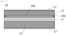
- An evaluation cell (all-solid-state lithium secondary battery of lithium-deposition type) having the form shown in Fig. 18 except that the negative electrode active material layer was not present was produced in the same manner as in Example 1 described above.
- the evaluation cell was produced, first, the positive electrode current collector, the positive electrode active material layer, and the solid electrolyte layer were formed in this order. Subsequently, an alumina layer was formed while the exposed surface of the solid electrolyte layer was masked, and then the mask was removed, and a carbon black layer and a negative electrode current collector were formed (laminated) in this order.
- a positive electrode lead and a negative electrode lead were connected to each of the positive electrode current collector and the negative electrode current collector of the evaluation cell prepared above, respectively, and a charge treatment was performed at a current density of 3 [mA/cm 2 ], 3.5 [mA/cm 2 ], or 4 [mA/cm 2 ] from SOC 0% in a thermostatic bath at 60°C, and the presence or absence of a short circuit of the evaluation cell within 30 minutes was examined. It was determined that a short circuit occurred when the voltage of the evaluation cell decreased during the charging process. In addition, the evaluation cell determined to have an occurrence of a short circuit was disassembled, and the inside of the cell was observed.
- Example 1 in which the solid electrolyte layer extends to the perimeter of the positive electrode active material layer in addition to disposing the ion-conductive reaction-suppressing layer and the ion-permeation suppressing layer, it is also found that the generation of dendrite was suppressed even by the current treatment at a higher current density.
Landscapes
- Chemical & Material Sciences (AREA)
- General Chemical & Material Sciences (AREA)
- Chemical Kinetics & Catalysis (AREA)
- Electrochemistry (AREA)
- Engineering & Computer Science (AREA)
- Manufacturing & Machinery (AREA)
- Materials Engineering (AREA)
- Inorganic Chemistry (AREA)
- Composite Materials (AREA)
- General Physics & Mathematics (AREA)
- Condensed Matter Physics & Semiconductors (AREA)
- Physics & Mathematics (AREA)
- Secondary Cells (AREA)
Abstract
Description
- The present invention relates to a lithium secondary battery.
- In recent years, research and development on an all-solid lithium secondary battery using an oxide-based or sulfide-based solid electrolyte as an electrolyte have been actively conducted. The solid electrolyte is a material mainly made of an ion conductor that enables ion conduction in a solid. For this reason, in an all-solid lithium secondary battery, in principle, various problems caused by combustible organic electrolyte solution do not occur unlike the conventional liquid-based lithium ion secondary battery. In general, use of a high-potential and large-capacity positive electrode material and a large-capacity negative electrode material can achieve significant improvement in output density and energy density of a battery.
- Conventionally, as one type of all-solid-state lithium secondary batteries, a so-called lithium-precipitation type in which lithium metal is precipitated on a negative electrode current collector in a charging process is known (see, e.g.,
U.S. Patent Application Publication No. 2019/0157723 ). In the charging process of such a lithium-precipitation type all-solid-state lithium secondary battery, lithium metal is precipitated between the solid electrolyte layer and the negative electrode current collector.U.S. Patent Application Publication No. 2019/0157723 discloses a technique in which a fine particle layer including fine particles of amorphous carbon, silicon, silver, tin, aluminum, bismuth, or the like is disposed between a negative electrode current collector and a solid electrolyte layer constituting a power-generating element of a lithium secondary battery. According toU.S. Patent Application Publication No. 2019/0157723 , by adopting such a configuration, when lithium metal is precipitated between the fine particle layer and the negative electrode current collector during charging, the fine particle layer serves as a protective layer for the lithium metal layer, and growth of dendrites from the lithium metal layer is suppressed, so that a short circuit of the lithium secondary battery, a decrease in capacity due to the short circuit, and the like are prevented. - However, according to the study of the present inventors, it has been found that even when the technique described in
U.S. Patent Application Publication No. 2019/0157723 is used, it is still impossible to prevent the growth of dendrites in some cases. - Therefore, an object of the present invention is to provide a means capable of more reliably suppressing the growth of dendrites in a lithium-precipitation type lithium secondary battery.
- The present inventors have conducted intensive studies in order to solve the above problem. As a result, the present inventors have found that the above problem can be solved by a lithium secondary battery including a lithium-precipitation type power-generating element, in which an ion conductive reaction suppressing layer that has lithium ion conductivity and suppresses reaction between lithium metal and a solid electrolyte is provided on a region where a positive electrode active material layer faces the negative electrode current collector, which is on a negative electrode current collector side of a surface of a solid electrolyte layer facing the negative electrode current collector, and an ion permeation suppressing layer that suppresses permeation of lithium ions is provided so as to be adjacent to at least a part of the perimeter of the solid electrolyte layer, and have arrived at the present invention.
- That is, one aspect of the present invention relates to a lithium secondary battery including a power-generating element having: a positive electrode in which a positive electrode active material layer containing a positive electrode active material capable of occluding and releasing lithium ions is disposed on a surface of a positive electrode current collector; a negative electrode that has a negative electrode current collector and in which lithium metal is precipitated on the negative electrode current collector during charging; and a solid electrolyte layer that is interposed between the positive electrode and the negative electrode and contains a solid electrolyte. The lithium secondary battery is characterized in that an ion conductive reaction suppressing layer that has lithium ion conductivity and suppresses reaction between the lithium metal and the solid electrolyte is provided on at least a part of a region where the positive electrode active material layer faces the negative electrode current collector on a main surface of the solid electrolyte layer facing the negative electrode current collector, and an ion permeation suppressing layer that suppresses permeation of lithium ions is provided so as to be adjacent to at least a part of the perimeter of the solid electrolyte layer.
- According to the present invention, the growth of dendrites in a lithium-precipitation type lithium secondary battery is more reliably suppressed.
-
-
FIG. 1 is a cross-sectional view schematically illustrating an overall structure of a laminate type (internal parallel connection type) all-solid lithium secondary battery (laminate type secondary battery) as one embodiment of the present invention. -
FIG. 2 is an enlarged cross-sectional view of a single battery layer of the laminate type secondary battery according to one embodiment of the present invention.FIG. 2 corresponds to a configuration of an evaluation cell produced in Example 1 to be described later. -
Fig. 3 is a perspective view of a laminated secondary battery according to one embodiment of the present invention. -
Fig. 4 is a side view as viewed from direction A illustrated inFig. 3 . -
Fig. 5 is a perspective view illustrating an appearance of a laminated secondary battery according to one embodiment of the present invention. -
Fig. 6 is an enlarged cross-sectional view of a single battery layer of a laminate type secondary battery according to another embodiment of the present invention.Fig. 6 corresponds to the configuration of an evaluation cell produced in Example 2 described later. -
Fig. 7 is an enlarged cross-sectional view of a single battery layer of a laminate type secondary battery according to still another embodiment of the present invention.Fig. 7 corresponds to the configuration of an evaluation cell produced in Example 3 described later. -
Fig. 8 is an enlarged cross-sectional view of a single battery layer of a laminate type secondary battery according to still another embodiment of the present invention.Fig. 8 corresponds to the configuration of an evaluation cell produced in Example 4 described later. -
Fig. 9 is an enlarged cross-sectional view of a single battery layer of a laminate type secondary battery according to still another embodiment of the present invention. -
Fig. 10 is an enlarged cross-sectional view of a single battery layer of a laminate type secondary battery according to still another embodiment of the present invention. -
Fig. 11 is an enlarged cross-sectional view of a single battery layer of a laminate type secondary battery according to still another embodiment of the present invention. -
Fig. 12 is an enlarged cross-sectional view of a single battery layer of a laminate type secondary battery according to still another embodiment of the present invention. -
Fig. 13 is an enlarged cross-sectional view of a single battery layer of a laminate type secondary battery according to still another embodiment of the present invention. -
Fig. 14 is an enlarged cross-sectional view of a single battery layer of a laminate type secondary battery according to still another embodiment of the present invention. -
Fig. 15 is an enlarged cross-sectional view of a single battery layer of a laminate type secondary battery according to still another embodiment of the present invention. -
Fig. 16 is an enlarged cross-sectional view of a single battery layer of a laminate type secondary battery according to still another embodiment of the present invention. -
Fig. 17 is an enlarged cross-sectional view of a single battery layer of a laminate type secondary battery according to still another embodiment of the present invention. -
Fig. 18 is an enlarged cross-sectional view of a single battery layer of a laminate type secondary battery corresponding to the configuration of an evaluation cell produced in Comparative Example 3. - Hereinafter, the present aspect will be described with reference to the drawings, but the technical scope of the present invention should be determined based on the description of the claims, and is not limited to the following embodiments. The dimensional ratios of the drawings are exaggerated for convenience of description and may differ from the actual ratios.
-
FIG. 1 is a cross-sectional view schematically illustrating an overall structure of a laminate type (internal parallel connection type) all-solid lithium secondary battery (hereinafter also simply referred to as "laminate type secondary battery") as one embodiment of the present invention. A laminate typesecondary battery 10a illustrated inFIG. 1 has a structure in which a substantially rectangular shaped power-generatingelement 21 in which a charge and discharge reaction actually proceeds is sealed inside alaminate film 29 as the battery outer casing body.FIG. 1 shows a cross section of the laminate type secondary battery during charging, and thus a negative electrodeactive material layer 13 made of lithium metal is present between a negative electrode current collector 11' and asolid electrolyte layer 17. The pressurizing member (not illustrated) applies a confining pressure to the laminate typesecondary battery 10a in the direction of lamination of the power-generatingelement 21. Accordingly, the volume of the power-generatingelement 21 is kept constant. - As illustrated in
FIG. 1 , the power-generatingelement 21 of the laminate typesecondary battery 10a of the present aspect has a configuration in which a negative electrode where the negative electrodeactive material layer 13 containing lithium metal is disposed on both surfaces of the negative electrode current collector 11', asolid electrolyte layer 17, and a positive electrode where a positive electrodeactive material layer 15 containing a lithium transition metal composite oxide is disposed on both surfaces of a positive electrodecurrent collector 11" are laminated. Specifically, the negative electrode, the solid electrolyte layer, and the positive electrode are laminated in this order such that one negative electrodeactive material layer 13 and the positive electrodeactive material layer 15 adjacent thereto face each other with thesolid electrolyte layer 17 interposed therebetween. Thus, the negative electrode, solid electrolyte layer, and positive electrode that are adjacent constitute onesingle battery layer 19. Therefore, it can be said that the laminate typesecondary battery 10a illustrated inFIG. 1 has a configuration in which a plurality of single battery layers 19 is laminated to be electrically connected in parallel. - The negative electrode current collector 11' and the positive electrode
current collector 11" have a structure in which a negative electrodecurrent collecting plate 25 and a positive electrodecurrent collecting plate 27 which are electrically connected to the respective electrodes (the negative electrode and the positive electrode) are respectively attached to the negative electrode current collector 11' and the positive electrodecurrent collector 11" and are led to an outside of thelaminate film 29 so as to be sandwiched between ends of thelaminate film 29. The negative electrodecurrent collecting plate 25 and the positive electrodecurrent collecting plate 27 may be attached to the negative electrode current collector 11' and the positive electrodecurrent collector 11" of the respective electrodes with a negative electrode terminal lead and a positive electrode terminal lead (not illustrated) interposed therebetween, respectively by ultrasonic welding, resistance welding, or the like as necessary. -
FIG. 2 is an enlarged cross-sectional view of thesingle battery layer 19 of the laminate type secondary battery according to one embodiment of the present invention. As illustrated inFIG. 2 , thesingle battery layer 19 constituting the laminate typesecondary battery 10a according to the present embodiment has a positive electrode including the positive electrodecurrent collector 11" and the positive electrodeactive material layer 15 disposed on the surface of the positive electrodecurrent collector 11". Further, thesolid electrolyte layer 17 containing a solid electrolyte is disposed on the surface of the positive electrodeactive material layer 15 on a side opposite to the positive electrodecurrent collector 11". Further, in the embodiment shown inFig. 2 , thesolid electrolyte layer 17 extends to reach the positive electrodecurrent collector 11" so as to cover the entire perimeter of the positive electrodeactive material layer 15. Then, in the embodiment shown inFig. 2 , a carbonblack layer 18a containing carbon black nanoparticles is provided on a region including the entire region of the positive electrodeactive material layer 15 facing the negative electrode current collector 11' on a main surface of thesolid electrolyte layer 17 facing the negative electrode current collector 11' (in other words, in a size larger than the positive electrodeactive material layer 15 when the power-generatingelement 21 is viewed in a plan view). Since the carbon black constituting the carbonblack layer 18a has lithium ion conductivity, the carbonblack layer 18a can conduct lithium ions. Therefore, the disposition of the carbonblack layer 18a does not hinder the progress of the battery reaction. Thecarbon black layer 18a also has a function of suppressing a reaction between lithium metal (negative electrode active material layer 13) precipitated on the negative electrode current collector 11' during charging and the solid electrolyte contained in thesolid electrolyte layer 17. Therefore, it can be said that thecarbon black layer 18a functions as an ion conductive reaction suppressing layer. - As shown in
Fig. 2 , in thesingle battery layer 19 constituting the laminatedsecondary battery 10a according to the present embodiment, analumina layer 18b containing alumina (aluminum oxide) nanoparticles is provided on the entire outer periphery of thesolid electrolyte layer 17. Alumina constituting thealumina layer 18b is a material having no lithium ion conductivity. Therefore, thealumina layer 18b functions as an ion permeation suppressing layer that suppresses permeation of lithium ions. As shown inFig. 2 , when thesolid electrolyte layer 17 extends so as to cover the perimeter of the positive electrodeactive material layer 15, and an alumina layer (ion-permeation suppressing layer) is provided adjacent to the perimeter of thesolid electrolyte layer 17 extending as described above, the QC performance of the battery obtained can be further improved. This is because thesolid electrolyte layer 17 is present extending to the perimeter of the positive electrodeactive material layer 15 and thus serves as a physical barrier, and in addition, the alumina layer (ion-permeation suppressing layer) has higher adhesion to thesolid electrolyte layer 17 than the positive electrodeactive material layer 15, so that growth of dendrite and a short circuit caused thereby can be more effectively prevented. -
Fig. 3 is a perspective view of a laminated secondary battery according to one embodiment of the present invention.Fig. 4 is a side view as viewed from direction A illustrated inFig. 3 . As illustrated inFIGS. 3 and 4 , a laminate typesecondary battery 100 according to the present embodiment includes the laminate typesecondary battery 10a illustrated inFig. 1 , twometal plates 200 sandwiching the laminate typesecondary battery 10a, andbolts 300 andnuts 400 as fastening members. The fastening members (thebolts 300 and the nuts 400) have a function of fixing the laminate typesecondary battery 10a in a state of being sandwiched by themetal plates 200. As a result, themetal plates 200 and the fastening members (thebolts 300 and the nuts 400) function as a pressurizing member that pressurizes (confines) a laminate typesecondary battery 10a in a direction of lamination of the laminate typesecondary battery 10a. The pressurizing member is not particularly limited as long as the pressurizing member can pressurize the laminate typesecondary battery 10a in the direction of lamination of the power-generating element. Typically, a combination of plates formed of a material having rigidity such as themetal plates 200 and the above-described fastening members is used as the pressurizing member. In addition to thebolts 300 and thenuts 400, a tension plate that fixes the end of themetal plate 200 so as to confine the laminate typesecondary battery 10a in the direction of lamination of the laminate typesecondary battery 10a, or the like may be used as a fastening member. - The lower limit of the load applied to the laminate type
secondary battery 10a (confining pressure in the direction of lamination of the laminate type secondary battery) is, for example, 0.1 MPa or more, preferably 1 MPa or more, more preferably 3 MPa or more, and still more preferably 5 MPa or more. The upper limit of the confining pressure in the direction of lamination of the laminate type secondary battery is, for example, 100 MPa or less, preferably 70 MPa or less, more preferably 40 MPa or less, and still more preferably 10 MPa or less. - Hereinafter, main components of the laminate type
secondary battery 10a described above will be described. - The material constituting the positive electrode current collector is not particularly limited. As a constituent material of the positive electrode current collector, for example, a metal or a resin having an electrical conduction property (such as a resin obtained by adding a conductive filler to a non-conductive polymer material) can be adopted.
- The current collector may have a single-layer structure made of a single material, or may have a laminated structure in which layers made of these materials are appropriately combined. From the viewpoint of weight reduction of the current collector, it is preferable to include at least a conductive resin layer made of a resin having an electrical conduction property. In addition, from the viewpoint of blocking the movement of lithium ions between single battery layers, a metal layer may be provided on a part of the current collector. The thickness of the positive electrode current collector is not particularly limited, but is, for example, from 10 to 100 µm.
- A positive electrode constituting the lithium secondary battery according to the present aspect has a positive electrode active material layer containing a positive electrode active material capable of absorbing and desorbing lithium ions. The positive electrode
active material layer 15 is disposed on the surface of the positive electrodecurrent collector 11" as illustrated inFIG. 1 . - The positive electrode active material is not particularly limited as long as it is a material capable of releasing lithium ions in the charging process of the secondary battery and occluding lithium ions in the discharging process. An example of such a positive electrode active material includes a material, which contains M1 element and O element, and in which the M1 element is at least one element selected from the group consisting of Li, Mn, Ni, Co, Cr, Fe, and P. Examples of such a positive electrode active material include layered rock salt-type active materials such as LiCoO2, LiMnO2, LiNiO2, and Li(Ni-Mn-Co)O2, spinel-type active materials such as LiMn2O4 and LiNi0.5Mn1.5O4, olivine-type active materials such as LiFePO4 and LiMnPO4, Si-containing active materials such as Li2FeSiO4 and Li2MnSiO4, and the like. Further, examples of an oxide active material other than those described above include Li4Ti5O12 and LiVO2. In some cases, two or more kinds of positive electrode active materials may be used in combination. It is needless to say that a positive electrode active material other than those described above may be used. In a preferred embodiment, the positive electrode
active material layer 15 constituting the lithium secondary battery according to the present aspect contains a layered rock salt-type active material (for example, Li(Ni-Mn-Co)O2) containing lithium and cobalt as the positive electrode active material from the viewpoint of output characteristics. - The content of the positive electrode active material in the positive electrode active material layer is not particularly limited, but for example, is preferably within a range of 30 to 99 mass , more preferably within a range of 40 to 90 mass , and still more preferably within a range of 45 to 80 mass .
- In the lithium secondary battery according to the present aspect, it is preferable that the positive electrode
active material layer 15 further contains a solid electrolyte. Examples of the solid electrolyte include a sulfide solid electrolyte and an oxide solid electrolyte. In a preferred embodiment of the secondary battery according to the present aspect, the solid electrolyte is preferably a sulfide solid electrolyte containing an S element, more preferably a sulfide solid electrolyte containing a Li element, an M element, and an S element, the M element is a sulfide solid electrolyte containing at least one element selected from the group consisting of P, Si, Ge, Sn, Ti, Zr, Nb, Al, Sb, Br, Cl, and I, and still more preferably a sulfide solid electrolyte containing an S element, a Li element, and a P element, from the viewpoint of exhibiting excellent lithium ion conductivity and following the volume change of the electrode active material associated with charging and discharging. - The content of the solid electrolyte in the positive electrode active material layer is not particularly limited, but is, for example, preferably within a range of 1 to 70 mass , more preferably within a range of 10 to 60 mass , and still more preferably within a range of 20 to 55 mass%.
- The positive electrode active material layer may further contain at least one of a conductive aid and a binder in addition to the positive electrode active material and the solid electrolyte.
- The thickness of the positive electrode active material layer varies depending on the configuration of the intended lithium secondary battery, but is, for example, preferably within the range of 0.1 to 1000 µm, and more preferably within a range of 40 to 100 µm.
- The solid electrolyte layer is a layer usually interposed between the positive electrode active material layer and the negative electrode current collector when fully discharged, and contains a solid electrolyte (usually as a main component). Since the specific form of the solid electrolyte contained in the solid electrolyte layer is the same as that described above, the detailed description thereof is omitted here. The content of the solid electrolyte in the solid electrolyte layer is preferably, for example, within a range of 10 to 100 mass , more preferably within a range of 50 to 100 mass , and still more preferably within a range of 90 to 100 mass% with respect to the total mass of the solid electrolyte layer.
- The solid electrolyte layer may further contain a binder in addition to the solid electrolyte described above. The thickness of the solid electrolyte layer varies depending on the configuration of the intended lithium secondary battery, but is, for example, preferably within a range of 0.1 to 1000 µm, and more preferably within a range of 10 to 40 µm.
- The negative electrode current collector is a conductive member that functions as a flow path for electrons emitted from a negative electrode toward a power source or flowing from an external load toward the negative electrode with the progression of the battery reaction (charge and discharge reaction). A material constituting the negative electrode current collector is not particularly limited. As the material constituting the negative electrode current collector, for example, a metal or a resin having conductivity can be adopted. The thickness of the negative electrode current collector is not particularly limited, but is, for example, from 10 to 100 µm.
- The lithium secondary battery according to the present aspect is a so-called lithium-deposition-type lithium secondary battery in which lithium metal is deposited on a negative electrode current collector in a charging process. A layer made of the lithium metal deposited on the negative electrode current collector in this charging process is a negative electrode active material layer of the lithium secondary battery according to the present aspect. Therefore, the thickness of the negative electrode active material layer increases with the progress of the charging process, and the thickness of the negative electrode active material layer decreases with the progress of the discharging process. The negative electrode active material layer need not be present when the battery has been completely discharged. However, in some cases, a negative electrode active material layer made of a certain amount of lithium metal may be disposed when the battery has been completely discharged. The thickness of the negative electrode active material layer (lithium metal layer) when the battery has been completely discharged is not particularly limited, but is usually from 0.1 to 1000 µm.
- The lithium secondary battery according to the present aspect is characterized in that an ion conductive reaction suppressing layer is provided on at least a part of the region where the positive electrode active material layer faces the negative electrode current collector on the main surface of the solid electrolyte layer facing the negative electrode current collector. The ion conductive reaction suppressing layer is a layer that has lithium ion conductivity and suppresses a reaction between a lithium metal (negative electrode active material layer) and a solid electrolyte. Therefore, by providing the ion conductive reaction suppressing layer, it is possible to prevent deterioration of the solid electrolyte and a decrease in battery capacity caused by a reaction between the lithium metal (negative electrode active material layer) and the solid electrolyte without hindering the progress of the battery reaction.
- Here, the phrase a material "has lithium ion conductivity" means that the lithium ion conductivity of the material at 25°C is 1 × 10⁻⁴ [S/cm] or more. On the other hand, the phrase a material "has no lithium ion conductivity" means that the lithium ion conductivity of the material at 25°C is less than 1 × 10⁻⁴ [S/cm]. In the lithium secondary battery according to the present aspect, the lithium ion conductivity at 25°C of the constituent material of the ion conductive reaction suppressing layer is 1 × 10⁻⁴ [S/cm] or more, preferably 1.5 × 10⁻⁴ [S/cm] or more, more preferably 2.0 × 10⁻⁴ [S/cm] or more, still more preferably 2.5 × 10⁻⁴ [S/cm] or more, and particularly preferably 3.0 × 10⁻⁴ [S/cm] or more.
- The constituent material of the ion conductive reaction suppressing layer is not particularly limited, and various materials capable of expressing the above-described function can be employed. Examples of the constituent material of the ion conductive reaction suppressing layer include nanoparticles having lithium ion conductivity (in the present description, nanoparticles as a constituent material of the ion conductive reaction suppressing layer are also simply referred to as "first nanoparticles"). When the ion conductive reaction suppressing layer contains the first nanoparticles, a lithium secondary battery having a particularly excellent function of the ion conductive reaction suppressing layer can be provided. Here, the "nanoparticles" mean particles having an average particle diameter on a scale of nanometers (nm). The "average particle diameter" of nanoparticles refers to a 50% cumulative diameter (D50) with respect to a particle diameter (longest distance among distances between any two points on the contour line of the observed particle) measured by observing a cross section of a layer containing nanoparticles with a scanning electron microscope (SEM). The average particle diameter of the first nanoparticles is preferably 500 nm or less, more preferably 300 nm or less, still more preferably 150 nm or less, particularly preferably 100 nm or less, and most preferably 60 nm or less. In particular, when the average particle diameter of the first nanoparticles is 60 nm or less, a lithium secondary battery particularly excellent in the effect of suppressing the growth of dendrites can be provided. The lower limit of the average particle diameter of the first nanoparticles is not particularly limited, and is usually 10 nm or more, and preferably 20 nm or more.
- Such first nanoparticles preferably contain, for example, one or two or more elements selected from the group consisting of carbon, gold, platinum, palladium, silicon, silver, aluminum, bismuth, tin, and zinc, and more preferably contain one or two or more of simple substances or alloys of these elements, from the viewpoint of being particularly excellent in the function as the ion conductive reaction suppressing layer. In addition, the first nanoparticles preferably contain carbon, and more preferably consist of a simple substance of carbon. Examples of the material composed of a simple substance of carbon include acetylene black, Vulcan (registered trademark), Black Pearl (registered trademark), carbon nanofiber, Ketjen Black (registered trademark), carbon nanotube, carbon nanohorn, carbon nanoballoon, and fullerene, and the like. Note that in a case where the ion conductive reaction suppressing layer contains such nanoparticles, the layer may further contain a binder.
- The method for forming the ion conductive reaction suppressing layer containing the first nanoparticles as described above on the surface of the solid electrolyte layer on the negative electrode current collector side is not particularly limited, and for example, a method can be adopted in which a slurry in which the nanoparticles and a binder as necessary are dispersed in an appropriate solvent is applied to the surface of the solid electrolyte layer on the negative electrode current collector side, and the solvent is dried. Further, the ion-conductive reaction-suppressing layer may be formed by bonding a coating film obtained by applying the slurry to the surface of a support such as stainless foil and drying the solvent to the surface of the solid electrolyte layer on the negative electrode current collector side using a technique such as hydrostatic pressing, and then peeling the support therefrom. Note that, in some cases, a continuous layer containing any of the above-described materials may be formed by a method such as sputtering or the like instead of the form of nanoparticles to form the ion conductive reaction suppressing layer.
- The first nanoparticles as the constituent material of the ion conductive reaction suppressing layer have been described above. Further, the ion conductive reaction suppressing layer may be composed of other constituent materials. Examples of other constituent materials include one or two or more lithium-containing compounds selected from the group consisting of lithium halide (lithium fluoride (LiF), lithium chloride (LiCl), lithium bromide (LiBr), lithium iodide (LiI)), a composite metal oxide represented by Li-M-O (M is one or two or more metal elements selected from the group consisting of Mg, Au, Al, Sn, and Zn), and a Li-Ba-TiO3 composite oxide. All of these materials are more stable in reductive decomposition due to contact with lithium metal than the solid electrolyte. That is, when the tendency of the solid electrolyte constituting the solid electrolyte layer to undergo reductive decomposition due to contact with lithium metal is compared with the tendency of the lithium-containing compound as the constituent material of the ion conductive reaction suppressing layer to undergo reductive decomposition due to contact with lithium metal, the latter tendency is smaller. Therefore, the lithium-containing compound can also function as an ion conductive reaction suppressing layer. The method for forming the ion conductive reaction suppressing layer containing such a lithium-containing compound is also not particularly limited, and for example, a continuous layer containing the above-described lithium-containing compound can be formed by a method such as sputtering or the like to form the ion conductive reaction suppressing layer.
- The average thickness of the ion conductive reaction suppressing layer is not particularly limited, and the ion conductive reaction suppressing layer may be disposed at a thickness capable of exerting the above-described function. However, when the average thickness of the ion conductive reaction suppressing layer is too large, the internal resistance is increased, which is a factor that reduces charge and discharge efficiency. Therefore, the average thickness of the ion conductive reaction suppressing layer is preferably smaller than the average thickness of the solid electrolyte layer. When the average thickness of the ion conductive reaction suppressing layer is too small, there is a possibility that the reaction suppressing effect by providing the ion conductive reaction suppressing layer cannot be sufficiently obtained. From these viewpoints, when the ion conductive reaction suppressing layer is a layer containing the first nanoparticles, the average thickness of the ion conductive reaction suppressing layer is preferably 300 nm to 20 um inclusive, more preferably 500 nm to 15 um inclusive, and still more preferably 1 um to 10 um inclusive. When the layer is a continuous layer made of a lithium-containing compound or the like formed by a method such as sputtering or the like, the thickness is preferably 0.5 nm to 20 nm inclusive. Note that, the "average thickness" of the ion conductive reaction suppressing layer means a value calculated as an arithmetic average value of the thicknesses measured respectively at several to several tens of different portions of the ion conductive reaction suppressing layer constituting the lithium secondary battery.
- The lithium secondary battery according to the present aspect is also characterized in that an ion-permeation suppressing layer is provided on at least a part of the perimeter of the solid electrolyte layer as shown in
Fig. 2 . The ion-permeation suppressing layer is a layer that suppresses permeation of lithium ions. Therefore, by providing the ion-permeation suppressing layer, even when dendrite is generated from lithium metal of the negative electrodeactive material layer 13, it is possible to effectively prevent occurrence of a short circuit due to growth of the dendrite bypassing the perimeter of thesolid electrolyte layer 17. - The constituent material of the ion permeation suppressing layer is not particularly limited, and various materials capable of expressing the above-described function can be adopted. The constituent material of the ion permeation suppressing layer is preferably a material having no lithium ion conductivity. In the lithium secondary battery according to the present aspect, the lithium ion conductivity at 25°C of the constituent material of the ion permeation suppressing layer is less than 1 × 10⁻⁴ [S/cm], and is preferably 1 × 10⁻⁵ [S/cm] or less, more preferably 1 × 10⁻⁶ [S/cm] or less, still more preferably 1 × 10⁻⁷ [S/cm] or less, and particularly preferably 1 × 10⁻⁸ [S/cm] or less. When the lithium ion conductivity of the constituent material of the ion permeation suppressing layer is a value within these ranges, the effect of suppressing the permeation of lithium ions is particularly large. As a relative relationship between the lithium ion conductivity of each of the constituent material of the ion conductive reaction suppressing layer and the constituent material of the ion permeation suppressing layer, the lithium ion conductivity (25°C) of the constituent material of the ion conductive reaction suppressing layer is preferably 10 times or more, more preferably 100 times or more, still more preferably 300 times or more, and particularly preferably 500 times or more the lithium ion conductivity (25°C) of the constituent material of the ion permeation suppressing layer. When the lithium ion conductivity of each material is different to this extent, it can be said that the lithium ion conductivity is preferable as a constituent material of each layer.
- Examples of the constituent material of the ion permeation suppressing layer include nanoparticles having no lithium ion conductivity (in the present description, nanoparticles as a constituent material of the ion permeation suppressing layer are also simply referred to as "second nanoparticles"). Since the ion permeation suppressing layer contains the second nanoparticles, a lithium secondary battery having a particularly excellent function of the ion permeation suppressing layer can be provided. The average particle diameter of the second nanoparticles is preferably 500 nm or less, more preferably 300 nm or less, still more preferably 150 nm or less, still more preferably 100 nm or less, particularly preferably 70 nm or less, and most preferably 40 nm or less. In particular, when the average particle diameter of the second nanoparticles is 40 nm or less, a lithium secondary battery particularly excellent in the effect of suppressing the growth of dendrites can be provided. The lower limit of the average particle diameter of the second nanoparticles is not particularly limited, and is usually 10 nm or more, and preferably 20 nm or more.
- From the viewpoint that lithium ion conductivity is low and the growth of dendrites can be effectively suppressed, the second nanoparticles preferably contain an oxide or nitride of a metal. Examples of such oxides or nitrides of a metal include oxides or nitrides of a metal such as aluminum, silicon, magnesium, calcium, potassium, tin, sodium, boron, titanium, lead, zirconium, and yttrium, and the like. Among them, it is preferable that the second nanoparticles contain oxides of these metals, and it is more preferable that the second nanoparticles contain an oxide of aluminum (aluminum oxide; alumina) or an oxide of silicon (silicon oxide; silica), and it is still more preferable that the second nanoparticles contain alumina. Note that in a case where the ion permeation suppressing layer contains such nanoparticles, the layer may further contain a binder.
- The method for forming the ion permeation suppressing layer containing the second nanoparticles as described above on the outer peripheral of the solid electrolyte layer is not particularly limited, and for example, a method can be adopted in which a slurry in which the nanoparticles and a binder as necessary are dispersed in an appropriate solvent is applied on the surface of the outer peripheral of the solid electrolyte layer, and the solvent is dried. The ion-permeation suppressing layer may be formed by bonding a coating film obtained by applying the slurry to the surface of a support such as stainless foil and drying the solvent to the surface of the perimeter of the solid electrolyte layer using a technique such as hydrostatic pressing, and then peeling the support therefrom. Note that, in some cases, a continuous layer containing any of the above-described materials may be formed by a method such as sputtering or the like instead of the form of nanoparticles to form the ion permeation suppressing layer.
- In some cases, the ion permeation suppressing layer may be formed of an inorganic powder such as S-B-Na-based glass frit and the like, a resin material, or a rubber material. In particular, since the resin material and the rubber material have elasticity, for example, even when an internal stress is generated in a region where the ion permeation suppressing layer is formed, the ion permeation suppressing layer is stretched without being broken, so that occurrence of a short circuit can be effectively prevented.
-
Fig. 5 is a perspective view illustrating an appearance of a laminated secondary battery according to one embodiment of the present invention. As shown inFig. 5 , the flat laminatedsecondary battery 50 has a rectangular flat shape, and apositive electrode tab 58 and anegative electrode tab 59 for extracting electric power are extended from both sides of the battery. The power-generatingelement 57 is wrapped in a battery outer casing body (laminate film 52) of the laminatedsecondary battery 50, the periphery of the battery outer casing body is heat-sealed, and the power-generatingelement 57 is hermetically sealed in a state where thepositive electrode tab 58 and thenegative electrode tab 59 are extended to the outside. - In the above description, the laminated structure and the arrangement form of each layer of the laminate type
secondary battery 10a (lithium secondary battery) according to the embodiment shown inFig. 2 have been described as an example, but the lithium secondary battery according to the present aspect can adopt various laminated structures and arrangement forms of each layer other than this. Examples of such other embodiments include embodiments shown inFigs. 6 to 8 . In the embodiment shown inFig. 6 , thesolid electrolyte layer 17 does not extend to the perimeter of the positive electrodeactive material layer 15, and is disposed only between the positive electrodeactive material layer 15 and thecarbon black layer 18a (ion-conductive reaction-suppressing layer). Then, analumina layer 18b (ion-permeation suppressing layer) is disposed on the perimeter of thesolid electrolyte layer 17. Further, in the embodiment shown inFig. 7 , thesolid electrolyte layer 17 and the positive electrodeactive material layer 15 are produced in the same size, and thealumina layer 18b (ion-permeation suppressing layer) is disposed adjacent to the perimeters of both layers. As described above, the configuration in which the ion-permeation suppressing layer is further adjacent to at least a part of the perimeter of the positive electrode active material layer in addition to the perimeter of the solid electrolyte layer is also one preferable form for effectively preventing the growth of dendrite and a short circuit caused thereby. Further, in the embodiment shown inFig. 8 , thecarbon black layer 18a (ion-conductive reaction-suppressing layer) extends so as to cover at least a part of the perimeter of thesolid electrolyte layer 17. Such a form is also one preferable form for effectively preventing the growth of dendrite and a short circuit caused thereby. In the lithium secondary battery according to the present aspect, for example, a laminated structure, an arrangement form of each layer, and the like as shown inFigs. 10 to 17 can be adopted in addition to the above-mentioned embodiments. - Although the case where the secondary battery according to the present aspect is an all-solid lithium secondary battery is described as an example, the lithium secondary battery according to the present aspect need not be an all solid type. Hence, the solid electrolyte layer may further contain a conventionally known liquid electrolyte (electrolyte solution).
- The following forms are also within the scope of the present invention: lithium secondary battery of claim 1 including the feature of claim 2; the lithium secondary battery of claim 1 or 2 including the feature of claim 3; the lithium secondary battery of any one of claims 1 to 3 including the feature of claim 4; the lithium secondary battery of any one of claims 1 to 4 including the feature of claim 5; the lithium secondary battery of any one of claims 1 to 5 including the feature of claim 6; the lithium secondary battery of any one of claims 1 to 6 including the feature of claim 7; the lithium secondary battery of claim 7 including the feature of claim 8; the lithium secondary battery of claim 7 or 8 including the feature of claim 9; the lithium secondary battery of any one of claims 7 to 9 including the feature of claim 10; and the lithium secondary battery of any one of claims 1 to 10 including the feature of
claim 11. - Hereinbelow, the present invention will be described in more detail with reference to Examples. However, the technical scope of the present invention is not limited to the following Examples. Hereinafter, the operation was performed in a glove box. Further, the instruments, devices, and the like used in the glove box were sufficiently dried in advance.
- First, LiNi0.8Mn0.1Co0.1O2 as a positive electrode active material, acetylene black as a conductive aid, and a sulfide solid electrolyte (LPS (Li2S-P2S5)) were weighed to have a mass ratio of 70:5:25, mixed in an agate mortar in a glove box, and then further mixed and stirred in a planetary ball mill. To 100 parts by mass of the resulting mixed powder, 2 parts by mass of styrene-butadiene rubber (SBR) was added, and mesitylene as a solvent was added to prepare a positive electrode active material slurry. Subsequently, the positive electrode active material slurry prepared above was applied onto a surface of a stainless steel (SUS) foil as a positive electrode current collector and dried to form a positive electrode active material layer (thickness: 50 um), thereby preparing a positive electrode.
- To 100 parts by mass of a sulfide solid electrolyte (LPS (Li2S-P2S5)), 2 parts by mass of the same styrene-butadiene rubber (SBR) was added, and mesitylene as a solvent was added to prepare a solid electrolyte slurry. Subsequently, the solid electrolyte slurry prepared above was applied onto a surface of a stainless foil as a support and dried to prepare a solid electrolyte layer (thickness: 30 um) on the surface of the stainless foil. The perimeter size of the solid electrolyte layer was set slightly larger than that of the positive electrode active material layer. Next, the positive electrode active material layer of the positive electrode prepared as described above and the solid electrolyte layer prepared as described above were superimposed in a manner of facing each other, and then bonded together by isostatic pressing (700 MPa, 25°C, 1 min) so that the outer circumference of the solid electrolyte layer covers entire outer perimeter of the positive electrode active material layer, and the stainless foil on the solid electrolyte layer side was peeled off to obtain a laminate of the positive electrode current collector and the positive electrode active material layer and the solid electrolyte layer.
- On the other hand, alumina nanoparticles were prepared as a constituent material of the ion-permeation suppressing layer. An alumina nanoparticle slurry was prepared by adding 10 parts by mass of styrene-butadiene rubber (SBR) to 100 parts by mass of the alumina nanoparticles, and adding mesitylene thereto as a solvent. Subsequently, an alumina layer (thickness: 5 µm) as an ion-permeation suppressing layer was produced on the surface of the stainless foil by applying the alumina nanoparticle slurry prepared above to the surface of the stainless foil as a support, followed by drying. The average particle diameter (D50) of alumina nanoparticles contained in the alumina layer thus produced was measured by SEM observation of a cross section of the alumina layer, and found to be 40 nm.
- Subsequently, the perimeter portion of the solid electrolyte layer in the laminate of the positive electrode current collector/positive electrode active material layer/solid electrolyte layer produced above and the alumina layer (ion-permeation suppressing layer) produced above were superimposed on each other so as to face each other, and then bonded to each other by hydrostatic pressing (700 MPa, 25°C, 1 min), and the stainless foil on the alumina layer side was peeled off to form an alumina layer on the entire perimeter of the solid electrolyte layer.
- Further, carbon black nanoparticles were provided as a constituent material of the ion conductive reaction suppressing layer. The same styrene-butadiene rubber (SBR) was added in an amount of 10 parts by mass for 100 parts by mass of the carbon black nanoparticles, and mesitylene was added as a solvent to prepare a carbon black nanoparticle slurry. Next, the carbon black nanoparticle slurry prepared above was applied onto a surface of a stainless foil as a support and dried to prepare a carbon black layer (thickness: 5 µm) as an ion conductive reaction suppressing layer on the surface of the stainless foil. The outer peripheral size of the carbon black layer (ion conductive reaction suppressing layer) was slightly larger than the region where the positive electrode active material layer faces the negative electrode current collector as shown in
Fig. 2 . The average particle diameter (D50) of carbon black nanoparticles contained in the carbon black layer thus prepared was measured by SEM observation of a cross section of the carbon black layer, and found to be 60 nm. - Thereafter, an end face of the alumina layer that covers the exposed surface of the solid electrolyte layer and the entire perimeter of the solid electrolyte layer in the laminate of the positive electrode current collector/positive electrode active material layer/solid electrolyte layer with the alumina layer formed above, and the carbon black layer (ion-conductive reaction-suppressing layer) produced above were superimposed on each other so as to face each other, and then bonded to each other by hydrostatic pressing (700 MPa, 25°C, 1 min), and the stainless foil on the carbon black layer side was peeled off to form a carbon black layer on the exposed surface of the solid electrolyte layer. Finally, a stainless foil as a negative electrode current collector was disposed in a manner of covering the carbon black layer and the alumina layer formed as described above, and an evaluation cell (lithium-precipitation type all-solid-state lithium secondary battery) in the form shown in
Fig. 2 was prepared except that the negative electrode active material layer was not present. - An evaluation cell (all-solid-state lithium secondary battery of lithium-deposition type) having the form shown in
Fig. 6 except that the negative electrode active material layer was not present was produced in the same manner as in Example 1 described above. When the evaluation cell was produced, the positive electrode current collector, the positive electrode active material layer, the solid electrolyte layer, the alumina layer, the carbon black layer, and the negative electrode current collector were formed (laminated) in this order. - An evaluation cell (all-solid-state lithium secondary battery of lithium-deposition type) having the form shown in
Fig. 7 except that the negative electrode active material layer was not present was produced in the same manner as in Example 1 described above. When the evaluation cell was produced, the positive electrode current collector, the positive electrode active material layer, the solid electrolyte layer, the alumina layer, the carbon black layer, and the negative electrode current collector were formed (laminated) in this order. - An evaluation cell (all-solid-state lithium secondary battery of lithium-deposition type) having the form shown in
Fig. 8 except that the negative electrode active material layer was not present was produced in the same manner as in Example 1 described above. When the evaluation cell was produced, the positive electrode current collector, the positive electrode active material layer, the solid electrolyte layer, the alumina layer, the carbon black layer, and the negative electrode current collector were formed (laminated) in this order. - An evaluation cell (lithium-precipitation type all-solid-state lithium secondary battery) of this Comparative Example was prepared by the same method as in Example 1 described above except that neither the ion conductive reaction suppressing layer (carbon black layer) nor the ion permeation suppressing layer (alumina layer) was formed.
- An evaluation cell (all-solid-state lithium secondary battery of lithium-deposition type) of this comparative example was produced in the same manner as in Example 2 described above except that neither the ion-conductive reaction-suppressing layer (carbon black layer) nor the ion-permeation suppressing layer (alumina layer) was formed.
- An evaluation cell (all-solid-state lithium secondary battery of lithium-deposition type) having the form shown in
Fig. 18 except that the negative electrode active material layer was not present was produced in the same manner as in Example 1 described above. When the evaluation cell was produced, first, the positive electrode current collector, the positive electrode active material layer, and the solid electrolyte layer were formed in this order. Subsequently, an alumina layer was formed while the exposed surface of the solid electrolyte layer was masked, and then the mask was removed, and a carbon black layer and a negative electrode current collector were formed (laminated) in this order. - A positive electrode lead and a negative electrode lead were connected to each of the positive electrode current collector and the negative electrode current collector of the evaluation cell prepared above, respectively, and a charge treatment was performed at a current density of 3 [mA/cm2], 3.5 [mA/cm2], or 4 [mA/cm2] from SOC 0% in a thermostatic bath at 60°C, and the presence or absence of a short circuit of the evaluation cell within 30 minutes was examined. It was determined that a short circuit occurred when the voltage of the evaluation cell decreased during the charging process. In addition, the evaluation cell determined to have an occurrence of a short circuit was disassembled, and the inside of the cell was observed. As a result, generation of dendrites due to lithium metal was confirmed in all of the evaluation cells. The results were shown in Table 1 below. Among the evaluation results shown in Table 1, those in which no short circuit occurs are indicated by "∘", and those in which a short circuit occurs are indicated by "×".
[Table 1] Ion-conductive reaction-suppressing layer (carbon black layer) Ion-permeation suppressing layer (alumina layer) Extension of solid electrolyte layer to perimeter of positive electrode active material layer Evaluation as to whether short circuit occurs With or without D50 [nm] With or without D50 [nm] Current density 3 mA/cm2 Current density 3.5 mA/ cm2 Current density 4 mA/cm2 Example 1 With 60 With 40 With ○ ○ ○ Example 2 With 60 With 40 Without ○ ○ × Example 3 With 60 With 40 Without ○ ○ × Example 4 With 60 With 40 Without ○ ○ × Comparative Example 1 Without - Without - With × × × Comparative Example 2 Without - Without - Without × × × Comparative Example 3 With 60 With*1) 40 Without ○ × × *1) The Ion-permeation suppressing layer was disposed on the perimeter of the carbon black layer. - From the results shown in Table 1, it is found that according to an aspect of the present invention, in a lithium secondary battery including a power generating element of lithium-deposition type, by providing the ion-conductive reaction-suppressing layer at the side of the negative electrode current collector of the solid electrolyte layer and disposing the ion-permeation suppressing layer adjacent to the perimeter of the solid electrolyte layer, the growth of dendrite can be more certainly suppressed as compared with a case where these layers are not disposed. In particular, in Example 1 in which the solid electrolyte layer extends to the perimeter of the positive electrode active material layer in addition to disposing the ion-conductive reaction-suppressing layer and the ion-permeation suppressing layer, it is also found that the generation of dendrite was suppressed even by the current treatment at a higher current density.
- This application is based on
Japanese Patent Application No. 2021-202389 filed on December 14, 2021
Claims (11)
- A lithium secondary battery comprising
a power-generating element comprising:a positive electrode in which a positive electrode active material layer containing a positive electrode active material capable of occluding and releasing lithium ions is disposed on a surface of a positive electrode current collector;a negative electrode that comprises a negative electrode current collector and in which lithium metal is precipitated on the negative electrode current collector during charging; anda solid electrolyte layer that is interposed between the positive electrode and the negative electrode and contains a solid electrolyte, whereinan ion conductive reaction suppressing layer that has lithium ion conductivity and suppresses reaction between the lithium metal and the solid electrolyte is provided on at least a part of a region where the positive electrode active material layer faces the negative electrode current collector on a main surface of the solid electrolyte layer facing the negative electrode current collector, andan ion permeation suppressing layer that suppresses permeation of lithium ions is provided so as to be adjacent to at least a part of the perimeter of the solid electrolyte layer. - The lithium secondary battery according to claim 1, wherein the solid electrolyte layer extends so as to cover at least a part of a perimeter of the positive electrode active material layer.
- The lithium secondary battery according to claim 1 or 2, wherein the ion-permeation suppressing layer is further adjacent to at least a part of a perimeter of the positive electrode active material layer.
- The lithium secondary battery according to claim 1 or 2, wherein the ion-conductive reaction-suppressing layer extends so as to cover at least a part of a perimeter of the solid electrolyte layer.
- The lithium secondary battery according to claim 1 or 2, wherein lithium ion conductivity of a constituent material of the ion conductive reaction suppressing layer is 100 times or more lithium ion conductivity of a constituent material of the ion permeation suppressing layer.
- The lithium secondary battery according to claim 1 or 2, wherein lithium ion conductivity of a constituent material of the ion permeation suppressing layer at 25°C is 1 × 10⁻⁵ [S/cm] or less.
- The lithium secondary battery according to claim 1 or 2, wherein the ion conductive reaction suppressing layer contains first nanoparticles having lithium ion conductivity, and the ion permeation suppressing layer contains second nanoparticles having no lithium ion conductivity.
- The lithium secondary battery according to claim 7, wherein an average particle diameter of the first nanoparticles is 60 nm or less and an average particle diameter of the second nanoparticles is 40 nm or less .
- The lithium secondary battery according to claim 8, wherein the first nanoparticles contain one or two or more kinds of elements selected from the group consisting of carbon, gold, platinum, palladium, silicon, silver, aluminum, bismuth, tin, and zinc.
- The lithium secondary battery according to claim 8, wherein the second nanoparticles contain an oxide or nitride of a metal.
- The lithium secondary battery according to claim 1 or 2, wherein the ion-conductive reaction-suppressing layer is provided in an area including the entire of the area, and the ion-permeation suppressing layer is provided over the entire perimeter of the solid electrolyte layer.
Applications Claiming Priority (2)
| Application Number | Priority Date | Filing Date | Title |
|---|---|---|---|
| JP2021202389 | 2021-12-14 | ||
| PCT/IB2022/000634 WO2023111680A1 (en) | 2021-12-14 | 2022-11-15 | Lithium secondary battery |
Publications (2)
| Publication Number | Publication Date |
|---|---|
| EP4451399A1 true EP4451399A1 (en) | 2024-10-23 |
| EP4451399A4 EP4451399A4 (en) | 2025-05-07 |
Family
ID=86773695
Family Applications (1)
| Application Number | Title | Priority Date | Filing Date |
|---|---|---|---|
| EP22905494.5A Pending EP4451399A4 (en) | 2021-12-14 | 2022-11-15 | LITHIUM SECONDARY BATTERY |
Country Status (5)
| Country | Link |
|---|---|
| US (1) | US20250062338A1 (en) |
| EP (1) | EP4451399A4 (en) |
| JP (1) | JP7754199B2 (en) |
| CN (1) | CN118369800A (en) |
| WO (1) | WO2023111680A1 (en) |
Cited By (1)
| Publication number | Priority date | Publication date | Assignee | Title |
|---|---|---|---|---|
| EP4525117A4 (en) * | 2022-05-13 | 2025-09-03 | Nissan Motor | Lithium secondary battery |
Family Cites Families (8)
| Publication number | Priority date | Publication date | Assignee | Title |
|---|---|---|---|---|
| KR101417268B1 (en) * | 2012-05-02 | 2014-07-08 | 현대자동차주식회사 | Lithium electrode for lithium battery and method for manufacturing the same |
| US11996564B2 (en) * | 2015-06-01 | 2024-05-28 | Forge Nano Inc. | Nano-engineered coatings for anode active materials, cathode active materials, and solid-state electrolytes and methods of making batteries containing nano-engineered coatings |
| US10686213B2 (en) * | 2017-05-18 | 2020-06-16 | Panasonic Intellectual Property Management Co., Ltd. | Battery |
| US10985407B2 (en) | 2017-11-21 | 2021-04-20 | Samsung Electronics Co., Ltd. | All-solid-state secondary battery including anode active material alloyable with lithium and method of charging the same |
| WO2019231892A1 (en) * | 2018-05-31 | 2019-12-05 | Robert Bosch Gmbh | Electrode configuration with a protrusion inhibiting separator |
| US10826127B2 (en) * | 2018-09-29 | 2020-11-03 | International Business Machines Corporation | Composite separator for lithium metal batteries |
| JP7366574B2 (en) * | 2019-04-10 | 2023-10-23 | 本田技研工業株式会社 | Solid electrolyte sheets, all solid batteries, separators and lithium ion batteries |
| KR102871360B1 (en) * | 2019-11-11 | 2025-10-15 | 삼성에스디아이 주식회사 | All Solid secondary battery |
-
2022
- 2022-11-15 EP EP22905494.5A patent/EP4451399A4/en active Pending
- 2022-11-15 CN CN202280081965.0A patent/CN118369800A/en active Pending
- 2022-11-15 WO PCT/IB2022/000634 patent/WO2023111680A1/en not_active Ceased
- 2022-11-15 JP JP2023567087A patent/JP7754199B2/en active Active
- 2022-11-15 US US18/719,127 patent/US20250062338A1/en active Pending
Cited By (1)
| Publication number | Priority date | Publication date | Assignee | Title |
|---|---|---|---|---|
| EP4525117A4 (en) * | 2022-05-13 | 2025-09-03 | Nissan Motor | Lithium secondary battery |
Also Published As
| Publication number | Publication date |
|---|---|
| JP7754199B2 (en) | 2025-10-15 |
| US20250062338A1 (en) | 2025-02-20 |
| CN118369800A (en) | 2024-07-19 |
| EP4451399A4 (en) | 2025-05-07 |
| JPWO2023111680A1 (en) | 2023-06-22 |
| WO2023111680A1 (en) | 2023-06-22 |
Similar Documents
| Publication | Publication Date | Title |
|---|---|---|
| KR101721786B1 (en) | All-solid-state battery | |
| US11424479B2 (en) | All-solid-state battery and method for manufacture thereof | |
| EP4318722A1 (en) | Lithium secondary battery | |
| KR20150018559A (en) | All-solid-state battery, and production method therefor | |
| EP4333110A1 (en) | Lithium secondary battery | |
| EP4325594A2 (en) | Electrode material, electrode, and all-solid-state battery | |
| US20250062338A1 (en) | Lithium Secondary Battery | |
| EP4528838A1 (en) | Secondary battery | |
| JP2021027013A (en) | All-solid battery | |
| JP7857786B2 (en) | Lithium-ion rechargeable battery | |
| EP4542582A1 (en) | Lithium ion conductor, lithium-ion battery, and lithium ion conductor manufacturing method | |
| EP4525117A1 (en) | Lithium secondary battery | |
| EP4528872A1 (en) | Lithium secondary battery | |
| JP7799544B2 (en) | All solid state battery | |
| JP7756257B2 (en) | Lithium secondary battery manufacturing method | |
| US20250174671A1 (en) | Lithium secondary battery | |
| US20250174738A1 (en) | Method for producing all-solid-state battery | |
| EP4611089A1 (en) | All-solid-state battery | |
| JP2026014571A (en) | Lithium secondary battery | |
| CN121079810A (en) | Lithium secondary battery | |
| JP2025167533A (en) | Lithium secondary battery | |
| CN117063323A (en) | Lithium secondary battery | |
| CN121586954A (en) | All-solid-state battery | |
| CN121646838A (en) | Manufacturing method of all-solid-state batteries | |
| WO2025141750A1 (en) | Lithium secondary battery |
Legal Events
| Date | Code | Title | Description |
|---|---|---|---|
| STAA | Information on the status of an ep patent application or granted ep patent |
Free format text: STATUS: UNKNOWN |
|
| STAA | Information on the status of an ep patent application or granted ep patent |
Free format text: STATUS: THE INTERNATIONAL PUBLICATION HAS BEEN MADE |
|
| PUAI | Public reference made under article 153(3) epc to a published international application that has entered the european phase |
Free format text: ORIGINAL CODE: 0009012 |
|
| STAA | Information on the status of an ep patent application or granted ep patent |
Free format text: STATUS: REQUEST FOR EXAMINATION WAS MADE |
|
| 17P | Request for examination filed |
Effective date: 20240607 |
|
| AK | Designated contracting states |
Kind code of ref document: A1 Designated state(s): AL AT BE BG CH CY CZ DE DK EE ES FI FR GB GR HR HU IE IS IT LI LT LU LV MC ME MK MT NL NO PL PT RO RS SE SI SK SM TR |
|
| DAV | Request for validation of the european patent (deleted) | ||
| DAX | Request for extension of the european patent (deleted) | ||
| A4 | Supplementary search report drawn up and despatched |
Effective date: 20250404 |
|
| RIC1 | Information provided on ipc code assigned before grant |
Ipc: H01M 4/62 20060101ALI20250331BHEP Ipc: H01M 4/38 20060101ALI20250331BHEP Ipc: H01M 4/134 20100101ALI20250331BHEP Ipc: H01M 10/0585 20100101ALI20250331BHEP Ipc: H01M 10/0562 20100101ALI20250331BHEP Ipc: H01M 10/052 20100101AFI20250331BHEP |