EP4451395A1 - Secondary battery - Google Patents
Secondary battery Download PDFInfo
- Publication number
- EP4451395A1 EP4451395A1 EP24158848.2A EP24158848A EP4451395A1 EP 4451395 A1 EP4451395 A1 EP 4451395A1 EP 24158848 A EP24158848 A EP 24158848A EP 4451395 A1 EP4451395 A1 EP 4451395A1
- Authority
- EP
- European Patent Office
- Prior art keywords
- secondary battery
- plate
- electrode assembly
- insulator
- wing portion
- Prior art date
- Legal status (The legal status is an assumption and is not a legal conclusion. Google has not performed a legal analysis and makes no representation as to the accuracy of the status listed.)
- Pending
Links
Images
Classifications
-
- H—ELECTRICITY
- H01—ELECTRIC ELEMENTS
- H01M—PROCESSES OR MEANS, e.g. BATTERIES, FOR THE DIRECT CONVERSION OF CHEMICAL ENERGY INTO ELECTRICAL ENERGY
- H01M10/00—Secondary cells; Manufacture thereof
- H01M10/04—Construction or manufacture in general
- H01M10/0422—Cells or battery with cylindrical casing
-
- H—ELECTRICITY
- H01—ELECTRIC ELEMENTS
- H01M—PROCESSES OR MEANS, e.g. BATTERIES, FOR THE DIRECT CONVERSION OF CHEMICAL ENERGY INTO ELECTRICAL ENERGY
- H01M10/00—Secondary cells; Manufacture thereof
-
- H—ELECTRICITY
- H01—ELECTRIC ELEMENTS
- H01M—PROCESSES OR MEANS, e.g. BATTERIES, FOR THE DIRECT CONVERSION OF CHEMICAL ENERGY INTO ELECTRICAL ENERGY
- H01M10/00—Secondary cells; Manufacture thereof
- H01M10/05—Accumulators with non-aqueous electrolyte
- H01M10/058—Construction or manufacture
-
- H—ELECTRICITY
- H01—ELECTRIC ELEMENTS
- H01M—PROCESSES OR MEANS, e.g. BATTERIES, FOR THE DIRECT CONVERSION OF CHEMICAL ENERGY INTO ELECTRICAL ENERGY
- H01M10/00—Secondary cells; Manufacture thereof
- H01M10/05—Accumulators with non-aqueous electrolyte
- H01M10/052—Li-accumulators
-
- H—ELECTRICITY
- H01—ELECTRIC ELEMENTS
- H01M—PROCESSES OR MEANS, e.g. BATTERIES, FOR THE DIRECT CONVERSION OF CHEMICAL ENERGY INTO ELECTRICAL ENERGY
- H01M50/00—Constructional details or processes of manufacture of the non-active parts of electrochemical cells other than fuel cells, e.g. hybrid cells
- H01M50/10—Primary casings; Jackets or wrappings
- H01M50/102—Primary casings; Jackets or wrappings characterised by their shape or physical structure
- H01M50/107—Primary casings; Jackets or wrappings characterised by their shape or physical structure having curved cross-section, e.g. round or elliptic
-
- H—ELECTRICITY
- H01—ELECTRIC ELEMENTS
- H01M—PROCESSES OR MEANS, e.g. BATTERIES, FOR THE DIRECT CONVERSION OF CHEMICAL ENERGY INTO ELECTRICAL ENERGY
- H01M50/00—Constructional details or processes of manufacture of the non-active parts of electrochemical cells other than fuel cells, e.g. hybrid cells
- H01M50/10—Primary casings; Jackets or wrappings
- H01M50/147—Lids or covers
- H01M50/166—Lids or covers characterised by the methods of assembling casings with lids
-
- H—ELECTRICITY
- H01—ELECTRIC ELEMENTS
- H01M—PROCESSES OR MEANS, e.g. BATTERIES, FOR THE DIRECT CONVERSION OF CHEMICAL ENERGY INTO ELECTRICAL ENERGY
- H01M50/00—Constructional details or processes of manufacture of the non-active parts of electrochemical cells other than fuel cells, e.g. hybrid cells
- H01M50/10—Primary casings; Jackets or wrappings
- H01M50/172—Arrangements of electric connectors penetrating the casing
- H01M50/174—Arrangements of electric connectors penetrating the casing adapted for the shape of the cells
- H01M50/179—Arrangements of electric connectors penetrating the casing adapted for the shape of the cells for cells having curved cross-section, e.g. round or elliptic
-
- H—ELECTRICITY
- H01—ELECTRIC ELEMENTS
- H01M—PROCESSES OR MEANS, e.g. BATTERIES, FOR THE DIRECT CONVERSION OF CHEMICAL ENERGY INTO ELECTRICAL ENERGY
- H01M50/00—Constructional details or processes of manufacture of the non-active parts of electrochemical cells other than fuel cells, e.g. hybrid cells
- H01M50/40—Separators; Membranes; Diaphragms; Spacing elements inside cells
- H01M50/471—Spacing elements inside cells other than separators, membranes or diaphragms; Manufacturing processes thereof
- H01M50/474—Spacing elements inside cells other than separators, membranes or diaphragms; Manufacturing processes thereof characterised by their position inside the cells
-
- H—ELECTRICITY
- H01—ELECTRIC ELEMENTS
- H01M—PROCESSES OR MEANS, e.g. BATTERIES, FOR THE DIRECT CONVERSION OF CHEMICAL ENERGY INTO ELECTRICAL ENERGY
- H01M50/00—Constructional details or processes of manufacture of the non-active parts of electrochemical cells other than fuel cells, e.g. hybrid cells
- H01M50/40—Separators; Membranes; Diaphragms; Spacing elements inside cells
- H01M50/471—Spacing elements inside cells other than separators, membranes or diaphragms; Manufacturing processes thereof
- H01M50/477—Spacing elements inside cells other than separators, membranes or diaphragms; Manufacturing processes thereof characterised by their shape
-
- H—ELECTRICITY
- H01—ELECTRIC ELEMENTS
- H01M—PROCESSES OR MEANS, e.g. BATTERIES, FOR THE DIRECT CONVERSION OF CHEMICAL ENERGY INTO ELECTRICAL ENERGY
- H01M50/00—Constructional details or processes of manufacture of the non-active parts of electrochemical cells other than fuel cells, e.g. hybrid cells
- H01M50/50—Current conducting connections for cells or batteries
- H01M50/528—Fixed electrical connections, i.e. not intended for disconnection
-
- H—ELECTRICITY
- H01—ELECTRIC ELEMENTS
- H01M—PROCESSES OR MEANS, e.g. BATTERIES, FOR THE DIRECT CONVERSION OF CHEMICAL ENERGY INTO ELECTRICAL ENERGY
- H01M50/00—Constructional details or processes of manufacture of the non-active parts of electrochemical cells other than fuel cells, e.g. hybrid cells
- H01M50/50—Current conducting connections for cells or batteries
- H01M50/543—Terminals
- H01M50/547—Terminals characterised by the disposition of the terminals on the cells
-
- H—ELECTRICITY
- H01—ELECTRIC ELEMENTS
- H01M—PROCESSES OR MEANS, e.g. BATTERIES, FOR THE DIRECT CONVERSION OF CHEMICAL ENERGY INTO ELECTRICAL ENERGY
- H01M50/00—Constructional details or processes of manufacture of the non-active parts of electrochemical cells other than fuel cells, e.g. hybrid cells
- H01M50/50—Current conducting connections for cells or batteries
- H01M50/572—Means for preventing undesired use or discharge
- H01M50/584—Means for preventing undesired use or discharge for preventing incorrect connections inside or outside the batteries
-
- H—ELECTRICITY
- H01—ELECTRIC ELEMENTS
- H01M—PROCESSES OR MEANS, e.g. BATTERIES, FOR THE DIRECT CONVERSION OF CHEMICAL ENERGY INTO ELECTRICAL ENERGY
- H01M50/00—Constructional details or processes of manufacture of the non-active parts of electrochemical cells other than fuel cells, e.g. hybrid cells
- H01M50/50—Current conducting connections for cells or batteries
- H01M50/572—Means for preventing undesired use or discharge
- H01M50/584—Means for preventing undesired use or discharge for preventing incorrect connections inside or outside the batteries
- H01M50/586—Means for preventing undesired use or discharge for preventing incorrect connections inside or outside the batteries inside the batteries, e.g. incorrect connections of electrodes
-
- H—ELECTRICITY
- H01—ELECTRIC ELEMENTS
- H01M—PROCESSES OR MEANS, e.g. BATTERIES, FOR THE DIRECT CONVERSION OF CHEMICAL ENERGY INTO ELECTRICAL ENERGY
- H01M50/00—Constructional details or processes of manufacture of the non-active parts of electrochemical cells other than fuel cells, e.g. hybrid cells
- H01M50/50—Current conducting connections for cells or batteries
- H01M50/572—Means for preventing undesired use or discharge
- H01M50/584—Means for preventing undesired use or discharge for preventing incorrect connections inside or outside the batteries
- H01M50/59—Means for preventing undesired use or discharge for preventing incorrect connections inside or outside the batteries characterised by the protection means
- H01M50/593—Spacers; Insulating plates
-
- Y—GENERAL TAGGING OF NEW TECHNOLOGICAL DEVELOPMENTS; GENERAL TAGGING OF CROSS-SECTIONAL TECHNOLOGIES SPANNING OVER SEVERAL SECTIONS OF THE IPC; TECHNICAL SUBJECTS COVERED BY FORMER USPC CROSS-REFERENCE ART COLLECTIONS [XRACs] AND DIGESTS
- Y02—TECHNOLOGIES OR APPLICATIONS FOR MITIGATION OR ADAPTATION AGAINST CLIMATE CHANGE
- Y02E—REDUCTION OF GREENHOUSE GAS [GHG] EMISSIONS, RELATED TO ENERGY GENERATION, TRANSMISSION OR DISTRIBUTION
- Y02E60/00—Enabling technologies; Technologies with a potential or indirect contribution to GHG emissions mitigation
- Y02E60/10—Energy storage using batteries
Definitions
- aspects of embodiments of the present disclosure relate to a secondary battery.
- a secondary battery is a battery that is designed to be charged and discharged.
- Low-capacity batteries are used in portable, small electronic devices, such as smart phones, feature phones, tablet computers, notebook computers, digital cameras, or camcorders, and large-capacity batteries are widely used as power sources for driving motors in hybrid vehicles and electric vehicles or as power storage devices (e.g., home or utility scale power storage devices).
- Secondary batteries can be classified into cylindrical, prismatic, or pouch-type secondary batteries based on their shape.
- Each of the cylindrical, prismatic, and pouch-type secondary battery generally includes an electrode assembly, a case, a cap assembly, etc., and has a structure in which the case is electrically connected to a negative electrode, and the cap assembly is electrically connected to a positive electrode.
- Embodiments of the present disclosure provide a secondary battery capable of securely and easily insulating an electrode assembly and a case from each other.
- a secondary battery includes: an electrode assembly; a can having a lower surface and a side surface and accommodating the electrode assembly therein; a cap plate coupled to an upper end of the can; a terminal on the lower surface of the can; and an insulator having a plate-shaped portion between the electrode assembly and the lower surface of the can and a wing portion extending upwardly from a circumference of the plate-shaped portion.
- the wing portion has a cut portion.
- the cut portion may extend downwardly from an upper end of the wing portion.
- the cut portion may extend a length smaller than a height of the wing portion.
- the cut portion may include a plurality of cut portions arranged along a circumferential direction of the wing portion.
- the plate-shaped portion may have a smaller diameter than the can.
- an upper end of the wing portion Before the insulator is installed into the can, an upper end of the wing portion may have a diameter larger than that of the can, and when the insulator is accommodated in the can, the wing portion may be deformed such that the upper end of the wing portion has a diameter corresponding to that of the can.
- An upper end of the wing portion may be in close contact with the side surface of the can.
- the cut portion may have a straight line shape.
- the cut portion may have a larger width at a lower portion thereof than at an upper portion thereof.
- the cut portion may have a V-shape.
- the wing portion may extend around a periphery of a lower portion of a side surface of the electrode assembly.
- the wing portion may contact an edge of a lower end of the electrode assembly.
- the expression "at least one of a, b, or c" indicates only a, only b, only c, both a and b, both a and c, both b and c, all of a, b, and c, or variations thereof.
- the terms “use,” “using,” and “used” may be considered synonymous with the terms “utilize,” “utilizing,” and “utilized,” respectively.
- the terms “substantially,” “about,” and similar terms are used as terms of approximation and not as terms of degree, and are intended to account for the inherent variations in measured or calculated values that would be recognized by those of ordinary skill in the art.
- first, second, third, etc. may be used herein to describe various elements, components, regions, layers, and/or sections, these elements, components, regions, layers, and/or sections should not be limited by these terms. These terms are used to distinguish one element, component, region, layer, or section from another element, component, region, layer, or section. Thus, a first element, component, region, layer, or section discussed below could be termed a second element, component, region, layer, or section without departing from the teachings of example embodiments.
- spatially relative terms such as “beneath,” “below,” “lower,” “above,” “upper,” and the like, may be used herein for ease of description to describe one element or feature's relationship to another element(s) or feature(s) as illustrated in the figures. It will be understood that the spatially relative terms are intended to encompass different orientations of the device in use or operation in addition to the orientation depicted in the figures. For example, if the device in the figures is turned over, elements described as “below” or “beneath” other elements or features would then be oriented “above” or “over” the other elements or features. Thus, the term “below” may encompass both an orientation of above and below. The device may be otherwise oriented (rotated 90 degrees or at other orientations), and the spatially relative descriptors used herein should be interpreted accordingly.
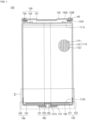
- FIG. 1 is a cross-sectional view of a secondary battery 100 according to an embodiment of the present disclosure
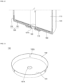
- FIG. 2 is a cross-sectional perspective view of the part II of FIG. 1 .
- the secondary battery 100 includes an electrode assembly 110, a can (herein, also referred to as a case) 120, a cap plate 130, a first gasket 140, a first current collector plate 150, a terminal 160, a second gasket 170, a second current collector plate 180, and an insulator 190.
- the electrode assembly 110 includes a first electrode plate 111, a second electrode plate 112, and a separator 113.
- the first electrode plate 111 may be any one of a negative electrode plate and a positive electrode plate.
- the first electrode plate 111 may include a current collector plate (e.g., a negative electrode current collector plate) made of a thin, conductive metal plate, such as copper or nickel foil or mesh, having a coating portion (e.g., a negative electrode coating portion) coated with an active material (e.g., a negative electrode active material) on one or both sides thereof and a non-coating portion 111A (e.g., a negative electrode non-coating portion) not coated with the negative electrode active material.
- the negative electrode active material may include, for example, a carbon-based material, silicon (Si), tin (Sn), tin oxide, tin alloy composite, a transition metal oxide, lithium metal nitrite, or a metal oxide.
- the second electrode plate 112 may be any one of a negative electrode plate and a positive electrode plate.
- the second electrode plate 112 may include a current collector plate (e.g., a positive electrode current collector plate) made of a thin, conductive metal plate, such as aluminium foil or mesh, having a coating portion (e.g., a positive electrode coating portion) coated with an active material (e.g., a positive electrode active material) on one or both sides thereof and a non-coating portion 112A (e.g., a positive electrode non-coating portion) not coated with the positive electrode active material.
- the positive electrode active material may include a chalcogenide compound, for example, a complex metal oxide, such as LiCoO 2 , LiMn 2 O 4 , LiNiO 2 , LiNiMnO 2 , etc.
- the separator 113 is interposed between the first electrode plate 111 and the second electrode plate 112 to prevent a short circuit between the first electrode plate 111 and the second electrode plate 112.
- the separator 113 may be made of, for example, polyethylene, polypropylene, or a porous copolymer of polyethylene and polypropylene.
- the electrode assembly 110 is formed by stacking the first electrode plate 111, the separator 113, the second electrode plate 112, and the separator 113 in that order and winding the stack around a common axis in the form of a so-called jelly-roll.
- the first electrode plate 111 and the second electrode plate 112 may be arranged partially offset from each other such that the non-coating portion 111A of the first electrode plate 111 protrudes from one side (e.g., the upper side in FIG. 1 ) of the electrode assembly 110 and the non-coating portion 112A of the second electrode plate 112 protrudes from the opposite side (e.g., the lower side in FIG. 1 ) of the electrode assembly 110.
- the can 120 may have a cylindrical shape overall.
- the can 120 may have a lower surface 121 formed in a disk shape and a side surface 122 extending upwardly from the circumference of the lower surface 121.
- the lower surface 121 and the side surface 122 may be integrally formed.
- the can 120 may be formed by a deep drawing process. Because the upper surface (e.g., the upper end) of the can 120 is open, the insulator 190, the electrode assembly 110, an electrolyte, etc. are inserted into the inside of the can 120 through the open upper end of the can 120, and then the upper end of the can 120 may be closed by the cap plate 130.
- the can 120 is illustrated as including a beading part (e.g., a bead) 122A and a crimping part (e.g., a crimp) 122B.
- a beading part e.g., a bead
- a crimping part e.g., a crimp
- the beading part 122A may be formed by concavely press-fitting the upper part of the can 120 inwardly after the electrode assembly 110 is inserted into the can 120.
- the beading part 122A prevents the electrode assembly 110 from being separated from the can 120 and supports the cap plate 130.
- the crimping part 122B is formed by inwardly bending the upper end of the can 120 after the cap plate 130 is seated on the beading part 122A to surround the edge of the cap plate 130 and, thus, fixes the cap plate 130.
- the can 120 has a hole 121A formed in the lower surface 121 for installing the terminal 160.
- the can 120 may be made of a conductive metal, such as steel, steel alloy, aluminium, or aluminium alloy, and may be electrically connected to the first electrode plate 111 of the electrode assembly 110 through the first current collector plate 150. Therefore, as described above, when the first electrode plate 111 is a negative electrode plate, the can 120 has a negative polarity.
- the cap plate 130 is coupled to the upper end of the can 120.
- the cap plate 130 may be insulated from the can 120 by the first gasket 140. That is, the cap plate 130 may not have any polarity (e.g., may be electrically floating). Therefore, the cap plate 130 does not necessarily have to be made of a conductive metal but, to provide sufficient rigidity, may be made of a metal.
- the cap plate 130 may have a notch 130A.
- the notch 130A acts as a safety vent. For example, when gas is generated inside the can 120, raising the pressure inside the can 120, the notch 130A may be spontaneously cut (e.g., may spontaneously burst) to release the gas and pressure, thereby preventing an uncontrolled explosion of the secondary battery 100.
- the notch 130A may be formed along an edge of the cap plate 130. Therefore, when the pressure is applied, the notch 130A can be cut (e.g., may burst) more easily, and when the notch 130A is cut, the fracture area (e.g., the open area or exhaust area) can be made as wide as possible so that the gas and pressure can be released quickly.
- the fracture area e.g., the open area or exhaust area
- the notch 130A may be formed in an inner surface of the cap plate 130. Accordingly, the notch 130A may not be unintentionally damaged or corroded due to external factors.
- the first gasket 140 is disposed between the can 120 and the cap plate 130 to tightly seal a space therebetween while insulating the can 120 and the cap plate 130 from each other.
- the first current collector plate 150 is disposed on the upper side of the electrode assembly 110 and is made of conductive metal to electrically connect the first electrode plate 111 of the electrode assembly 110 and the can 120.
- the first current collector plate 150 includes an electrode plate contact portion 151 in contact with the non-coating portion 111A of the first electrode plate 111 of the electrode assembly 110, a can contact portion 152 in contact with the can 120, and a connecting portion 153 connecting (e.g., extending between) the electrode plate contact portion 151 and the can contact portion 152.
- the connecting portion 153 may be bent at least once. In the drawing, the connecting portion 153 is shown as being bent three times. Through this bending, even if the electrode assembly 110 partially moves or expands within the can 120, the connecting portion 153 elastically absorbs such movement, thereby stably maintaining the electrically connected state between the electrode assembly 110 and the can 120.
- the electrode plate contact portion 151 of the first current collector plate 150 may be welded to the non-coating portion 111A of the first electrode plate 111 of the electrode assembly 110.
- the can contact portion 152 is illustrated as being interposed and fixed between the beading part 122A of the can 120 and the first gasket 140.
- the electrode plate contact portion 151 of the first current collector plate 150 is welded to the non-coating portion 111A of the first electrode plate 111 of the electrode assembly 110, and the can contact portion 152 of the first current collector plate 150 is disposed on the beading part 122A of the can 120, thereby electrically connecting the first electrode plate 111 of the electrode assembly 110 and the can 120.
- the first gasket 140 is placed on the beading part 122A of the can 120, covering the can contact portion 152 of the first current collector plate 150, the cap plate 130 is seated thereon, and the crimping part 122B is then formed by bending the upper end of the can 120 together with the first gasket 140, thereby pressing and fixing the cap plate 130 and the first current collector plate 150.
- the cap plate 130 may be directly welded and fixed to the upper end of the can 120.
- the first gasket 140 may be omitted and the can contact portion 152 of the first current collector plate 150 may be welded to the can 120 or to the cap plate 130.
- the terminal 160 is installed in the hole 121A in the lower surface 121 of the can 120 and is made of a conductive metal to be electrically connected to the second electrode plate 112 of the electrode assembly 110 through the second current collector plate 180. Therefore, as described above, when the second electrode plate 112 is a positive electrode plate, the terminal 160 has a positive polarity.
- the terminal 160 has a larger diameter than the hole 121A in the lower surface 121 of the can 120 and may have an outer portion 161 supported on (e.g., contacting) the outside of the lower surface 121, an inner portion 162 having a larger diameter than the hole 121A in the lower surface 121 of the can 120 and supported from (e.g., contacting) the inside of the lower surface 121, and a connecting portion 163 inserted through (or extending through) the hole 121A in the lower surface 121 of the can 120 and connecting the outer portion 161 and the inner portion 162.
- the terminal 160 may be installed, for example, by riveting.
- the inner portion 162 and the connecting portion 163 are inserted into the hole 121A when the inner portion 162 has a diameter equal to or smaller than the hole 121A in the lower surface 121 of the can 120, and then, the inner portion 162 is deformed to have a larger diameter than the hole 121A, thereby fastening the terminal 160 to the hole 121A.
- the second gasket 170 is disposed between the can 120 and the terminal 160 to tightly seal a space therebetween while insulating the can 120 and the terminal 160 from each other.
- the second current collector plate 180 is disposed below the electrode assembly 110 and is made of a conductive metal to electrically connect the second electrode plate 112 of the electrode assembly 110 to the terminal 160. To this end, the second current collector plate 180 may be welded to the non-coating portion 112A of the second electrode plate 112 of the electrode assembly 110 and to the inner portion 162 of the terminal 160.
- FIG. 3 is a cross-sectional perspective view of the insulator 190 in the secondary battery 100 shown in FIGS. 1 and 2 .
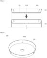
- FIG. 4 is a schematic diagram of the secondary battery 100 illustrating a process of inserting the insulator 190 into the can 120.
- the insulator 190 is disposed under the second current collector plate 180 to insulate the can 120 from the electrode assembly 110 and the second current collector plate 180.
- the insulator 190 may have a plate-shaped portion 191 formed in a shape corresponding to the lower surface 121 of the can 120 and a wing portion 192 extending upwardly from the circumference of the plate-shaped portion 191.
- the plate-shaped portion 191 may have a diameter approximately equal to or slightly smaller than that of the can 120.
- the plate-shaped portion 191 may have a slightly smaller diameter than the can 120 so that the insulator 190 can be smoothly inserted into the can 120.
- the plate-shaped portion 191 may have a hole 191A to provide a space in which the terminal 160 is installed.
- the wing portion 192 extends upwardly from the circumference of the plate-shaped portion 191 to surround (e.g., to surround a periphery of) the lower side of the electrode assembly 110.
- the wing portion 192 may be formed to have an upper end having a slightly larger diameter than the can 120 at an initial stage, that is, before the insulator 190 is inserted into the can 120. Therefore, as the insulator 190 is inserted into the can 120, the upper end of the wing portion 192 may be deformed to have a diameter corresponding to that of the can 120, that is, the wing portion 192 can be brought into close contact with the side surface 122 of the can 120 in an interference-fit manner (see, e.g., FIG. 4 ).
- the wing portion 192 has a cut portion 192A so that the upper end thereof can be more easily deformed into an intended shape as it is inserted into the can 120.
- the cut portion 192A is formed to extend downwardly from the upper end of the wing portion 192.
- the cut portion 192A may be formed by extending to a boundary between the plate-shaped portion 191 and the wing portion 192, that is, the cut portion 192A may have a length corresponding to the height of the wing portion 192. In another embodiment, the cut portion 192A may be formed to be even longer than the height of the wing portion 192, that is, to extend into the plate-shaped portion 191 from the wing portion 192.
- the cut portion 192A is formed to be shorter than the height of the wing portion 192 to ensure sufficient rigidity by leaving material of the wing portion 192 between the cut portion 192A and the plate-shaped portion 191. That is, the cut portion 192A ends before reaching a boundary between the plate-shaped portion 191 and the wing portion 192.
- the wing portion 192 may be formed to have a plurality of wing portions separated by a corresponding number of cut portions 192A, and the wing portions 192 may be arranged at intervals (e.g., at specific or repeating intervals) along the circumferential direction.
- the wing portion 192 is illustrated as having three wing portions arranged at equal intervals.
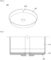
- FIG. 5 is a perspective view of an insulator 290 of a secondary battery according to another embodiment of the present disclosure.
- the cut portion 192A is formed to extend in a straight line with a certain width (see, e.g., FIG. 3 ).
- the cut portion 292A has a portion (e.g., an upper portion) extending in a straight line shape and having a constant width and another portion (e.g., a lower portion) having a larger width at the lower portion of the cut portion 292A.
- the other portion of the cut portion 292A may be formed in a circular shape (see, e.g., FIG. 5 ).
- FIG. 6 is a perspective view of an insulator 390 according to another embodiment of the present disclosure.
- the cut portion 192A is formed to extend in a straight line having a certain width (see, e.g., FIG. 3 ), but in the insulator 390, the cut portion 392A is formed in a V-shape (see, e.g., FIG. 6 ).
- FIG. 7 is a cross-sectional view of a secondary battery according to another embodiment of the present disclosure, illustrating the area around an insulator 490.
- the wing portion 192 of the insulator 190 extends relatively long to surround the lower side of the electrode assembly 110, but in the secondary battery shown in FIG. 7 , the wing portion 492 of the insulator 490 extends relatively short to be in contact with the lower edge of the electrode assembly 410.
- the electrode assembly 410 can be designed to be larger using space that would otherwise be occupied by the thickness of the wing portion 192 of the insulator 190 in the secondary battery 100.
- the battery capacity can be increased.
- the cut portion of the wing portion 492 of the insulator 490 may be formed to have a certain width by extending in a straight line, similar to the embodiment shown in FIG. 3 , may be formed to have a constant width by extending in a straight line shape and then formed to have a larger width at the lower portion thereof, for example, formed in a circular shape, similar to the embodiment shown in FIG. 5 , or may be formed in a V-shape, similar to the embodiment shown in FIG. 6 .
- embodiments of the present disclosure provide a secondary battery in which an electrode assembly and a can are insulated from each other by using an insulator, and the insulator has a wing portion and a cut portion formed in the wing portion.
- the wing portion can be easily deformed to a diameter corresponding to that of the can by the cut portion, thereby allowing the insulator to be easily inserted into the can in an interference-fit manner.
Landscapes
- Chemical & Material Sciences (AREA)
- Chemical Kinetics & Catalysis (AREA)
- Electrochemistry (AREA)
- General Chemical & Material Sciences (AREA)
- Engineering & Computer Science (AREA)
- Manufacturing & Machinery (AREA)
- Connection Of Batteries Or Terminals (AREA)
Abstract
A secondary battery (100) includes: an electrode assembly (110); a can (120) having a lower surface and a side surface and accommodating the electrode assembly therein; a cap plate (130) coupled to an upper end of the can; a terminal (160) on the lower surface of the can; and an insulator (190) having a plate-shaped portion (191) between the electrode assembly and the lower surface of the can and a wing portion (192) extending upwardly from a circumference of the plate-shaped portion. The wing portion has a cut portion (192A).
Description
- Aspects of embodiments of the present disclosure relate to a secondary battery.
- Different from a primary battery that is not designed to be charged, a secondary battery is a battery that is designed to be charged and discharged. Low-capacity batteries are used in portable, small electronic devices, such as smart phones, feature phones, tablet computers, notebook computers, digital cameras, or camcorders, and large-capacity batteries are widely used as power sources for driving motors in hybrid vehicles and electric vehicles or as power storage devices (e.g., home or utility scale power storage devices).
- Secondary batteries can be classified into cylindrical, prismatic, or pouch-type secondary batteries based on their shape. Each of the cylindrical, prismatic, and pouch-type secondary battery generally includes an electrode assembly, a case, a cap assembly, etc., and has a structure in which the case is electrically connected to a negative electrode, and the cap assembly is electrically connected to a positive electrode.
- The above information disclosed in this Background section is for enhancement of understanding of the background of the present disclosure, and therefore, it may contain information that does not constitute prior art.
- Embodiments of the present disclosure provide a secondary battery capable of securely and easily insulating an electrode assembly and a case from each other.
- A secondary battery, according to an embodiment of the present disclosure, includes: an electrode assembly; a can having a lower surface and a side surface and accommodating the electrode assembly therein; a cap plate coupled to an upper end of the can; a terminal on the lower surface of the can; and an insulator having a plate-shaped portion between the electrode assembly and the lower surface of the can and a wing portion extending upwardly from a circumference of the plate-shaped portion. The wing portion has a cut portion.
- The cut portion may extend downwardly from an upper end of the wing portion.
- The cut portion may extend a length smaller than a height of the wing portion.
- The cut portion may include a plurality of cut portions arranged along a circumferential direction of the wing portion.
- The plate-shaped portion may have a smaller diameter than the can.
- Before the insulator is installed into the can, an upper end of the wing portion may have a diameter larger than that of the can, and when the insulator is accommodated in the can, the wing portion may be deformed such that the upper end of the wing portion has a diameter corresponding to that of the can.
- An upper end of the wing portion may be in close contact with the side surface of the can.
- The cut portion may have a straight line shape.
- The cut portion may have a larger width at a lower portion thereof than at an upper portion thereof.
- The cut portion may have a V-shape.
- The wing portion may extend around a periphery of a lower portion of a side surface of the electrode assembly.
- The wing portion may contact an edge of a lower end of the electrode assembly.
- At least some of the above and other features of the invention are set out in the claims.
-
-
FIG. 1 is a cross-sectional view of a secondary battery according to an embodiment of the present disclosure. -
FIG. 2 is a cross-sectional perspective view of the part II ofFIG. 1 . -
FIG. 3 is a perspective view of an insulator in the secondary battery shown inFIGS. 1 and2 . -
FIG. 4 is a schematic diagram of the secondary battery shown inFIGS. 1 to 3 illustrating a process of inserting an insulator into a can. -
FIG. 5 is a perspective view of an insulator of a secondary battery according to another embodiment of the present disclosure. -
FIG. 6 is a perspective view of an insulator of a secondary battery according to another embodiment of the present disclosure. -
FIG. 7 is a cross-sectional view of an insulator of a secondary battery according to another embodiment of the present disclosure. - Hereinafter, embodiments of the present disclosure will be described, in detail, with reference to the accompanying drawings. These embodiments of the present disclosure are provided to more completely explain the present disclosure to those skilled in the art, and the following embodiments may be modified to have various other forms. In other words, the present disclosure may be embodied in many different forms and should not be construed as being limited to the embodiments set forth herein. Rather, these embodiments are provided so that this disclosure will be thorough and complete and will convey the aspects and features of the present disclosure to those skilled in the art.
- It will be understood that when an element or layer is referred to as being "on," "connected to," or "coupled to" another element or layer, it may be directly on, connected, or coupled to the other element or layer or one or more intervening elements or layers may also be present. When an element or layer is referred to as being "directly on," "directly connected to," or "directly coupled to" another element or layer, there are no intervening elements or layers present. For example, when a first element is described as being "coupled" or "connected" to a second element, the first element may be directly coupled or connected to the second element or the first element may be indirectly coupled or connected to the second element via one or more intervening elements.
- In the figures, dimensions of the various elements, layers, etc. may be exaggerated for clarity of illustration. The same reference numerals designate the same elements. As used herein, the term "and/or" includes any and all combinations of one or more of the associated listed items. Further, the use of "may" when describing embodiments of the present disclosure relates to "one or more embodiments of the present disclosure." Expressions, such as "at least one of" and "any one of," when preceding a list of elements, modify the entire list of elements and do not modify the individual elements of the list. For example, the expression "at least one of a, b, or c" indicates only a, only b, only c, both a and b, both a and c, both b and c, all of a, b, and c, or variations thereof. As used herein, the terms "use," "using," and "used" may be considered synonymous with the terms "utilize," "utilizing," and "utilized," respectively. As used herein, the terms "substantially," "about," and similar terms are used as terms of approximation and not as terms of degree, and are intended to account for the inherent variations in measured or calculated values that would be recognized by those of ordinary skill in the art.
- It will be understood that, although the terms first, second, third, etc. may be used herein to describe various elements, components, regions, layers, and/or sections, these elements, components, regions, layers, and/or sections should not be limited by these terms. These terms are used to distinguish one element, component, region, layer, or section from another element, component, region, layer, or section. Thus, a first element, component, region, layer, or section discussed below could be termed a second element, component, region, layer, or section without departing from the teachings of example embodiments.
- Spatially relative terms, such as "beneath," "below," "lower," "above," "upper," and the like, may be used herein for ease of description to describe one element or feature's relationship to another element(s) or feature(s) as illustrated in the figures. It will be understood that the spatially relative terms are intended to encompass different orientations of the device in use or operation in addition to the orientation depicted in the figures. For example, if the device in the figures is turned over, elements described as "below" or "beneath" other elements or features would then be oriented "above" or "over" the other elements or features. Thus, the term "below" may encompass both an orientation of above and below. The device may be otherwise oriented (rotated 90 degrees or at other orientations), and the spatially relative descriptors used herein should be interpreted accordingly.
- The terminology used herein is for the purpose of describing embodiments of the present disclosure and is not intended to be limiting of the present disclosure. As used herein, the singular forms "a" and "an" are intended to include the plural forms as well, unless the context clearly indicates otherwise. It will be further understood that the terms "includes," "including," "comprises," and/or "comprising," when used in this specification, specify the presence of stated features, integers, steps, operations, elements, and/or components but do not preclude the presence or addition of one or more other features, integers, steps, operations, elements, components, and/or groups thereof.
-
FIG. 1 is a cross-sectional view of asecondary battery 100 according to an embodiment of the present disclosure, andFIG. 2 is a cross-sectional perspective view of the part II ofFIG. 1 . - Referring to
FIGS. 1 and2 , thesecondary battery 100, according to an embodiment of the present disclosure, includes anelectrode assembly 110, a can (herein, also referred to as a case) 120, acap plate 130, afirst gasket 140, a firstcurrent collector plate 150, aterminal 160, asecond gasket 170, a secondcurrent collector plate 180, and aninsulator 190. - The
electrode assembly 110 includes a first electrode plate 111, asecond electrode plate 112, and aseparator 113. - The first electrode plate 111 may be any one of a negative electrode plate and a positive electrode plate. For example, when the first electrode plate 111 is a negative electrode plate, the first electrode plate 111 may include a current collector plate (e.g., a negative electrode current collector plate) made of a thin, conductive metal plate, such as copper or nickel foil or mesh, having a coating portion (e.g., a negative electrode coating portion) coated with an active material (e.g., a negative electrode active material) on one or both sides thereof and a
non-coating portion 111A (e.g., a negative electrode non-coating portion) not coated with the negative electrode active material. The negative electrode active material may include, for example, a carbon-based material, silicon (Si), tin (Sn), tin oxide, tin alloy composite, a transition metal oxide, lithium metal nitrite, or a metal oxide. - The
second electrode plate 112 may be any one of a negative electrode plate and a positive electrode plate. For example, when thesecond electrode plate 112 is a positive electrode plate, thesecond electrode plate 112 may include a current collector plate (e.g., a positive electrode current collector plate) made of a thin, conductive metal plate, such as aluminium foil or mesh, having a coating portion (e.g., a positive electrode coating portion) coated with an active material (e.g., a positive electrode active material) on one or both sides thereof and anon-coating portion 112A (e.g., a positive electrode non-coating portion) not coated with the positive electrode active material. The positive electrode active material may include a chalcogenide compound, for example, a complex metal oxide, such as LiCoO2, LiMn2O4, LiNiO2, LiNiMnO2, etc. - The
separator 113 is interposed between the first electrode plate 111 and thesecond electrode plate 112 to prevent a short circuit between the first electrode plate 111 and thesecond electrode plate 112. Theseparator 113 may be made of, for example, polyethylene, polypropylene, or a porous copolymer of polyethylene and polypropylene. - The
electrode assembly 110 is formed by stacking the first electrode plate 111, theseparator 113, thesecond electrode plate 112, and theseparator 113 in that order and winding the stack around a common axis in the form of a so-called jelly-roll. The first electrode plate 111 and thesecond electrode plate 112 may be arranged partially offset from each other such that thenon-coating portion 111A of the first electrode plate 111 protrudes from one side (e.g., the upper side inFIG. 1 ) of theelectrode assembly 110 and thenon-coating portion 112A of thesecond electrode plate 112 protrudes from the opposite side (e.g., the lower side inFIG. 1 ) of theelectrode assembly 110. - The can 120 may have a cylindrical shape overall.
- In some embodiments, the
can 120 may have alower surface 121 formed in a disk shape and aside surface 122 extending upwardly from the circumference of thelower surface 121. Thelower surface 121 and theside surface 122 may be integrally formed. For example, thecan 120 may be formed by a deep drawing process. Because the upper surface (e.g., the upper end) of thecan 120 is open, theinsulator 190, theelectrode assembly 110, an electrolyte, etc. are inserted into the inside of thecan 120 through the open upper end of thecan 120, and then the upper end of thecan 120 may be closed by thecap plate 130. - In the drawings, the
can 120 is illustrated as including a beading part (e.g., a bead) 122A and a crimping part (e.g., a crimp) 122B. - The
beading part 122A may be formed by concavely press-fitting the upper part of thecan 120 inwardly after theelectrode assembly 110 is inserted into thecan 120. Thebeading part 122A prevents theelectrode assembly 110 from being separated from thecan 120 and supports thecap plate 130. - The crimping
part 122B is formed by inwardly bending the upper end of thecan 120 after thecap plate 130 is seated on thebeading part 122A to surround the edge of thecap plate 130 and, thus, fixes thecap plate 130. - In addition, the
can 120 has ahole 121A formed in thelower surface 121 for installing theterminal 160. - The can 120 may be made of a conductive metal, such as steel, steel alloy, aluminium, or aluminium alloy, and may be electrically connected to the first electrode plate 111 of the
electrode assembly 110 through the firstcurrent collector plate 150. Therefore, as described above, when the first electrode plate 111 is a negative electrode plate, thecan 120 has a negative polarity. - The
cap plate 130 is coupled to the upper end of thecan 120. Thecap plate 130 may be insulated from thecan 120 by thefirst gasket 140. That is, thecap plate 130 may not have any polarity (e.g., may be electrically floating). Therefore, thecap plate 130 does not necessarily have to be made of a conductive metal but, to provide sufficient rigidity, may be made of a metal. - The
cap plate 130 may have anotch 130A. Thenotch 130A acts as a safety vent. For example, when gas is generated inside thecan 120, raising the pressure inside thecan 120, thenotch 130A may be spontaneously cut (e.g., may spontaneously burst) to release the gas and pressure, thereby preventing an uncontrolled explosion of thesecondary battery 100. - The
notch 130A may be formed along an edge of thecap plate 130. Therefore, when the pressure is applied, thenotch 130A can be cut (e.g., may burst) more easily, and when thenotch 130A is cut, the fracture area (e.g., the open area or exhaust area) can be made as wide as possible so that the gas and pressure can be released quickly. - In addition, the
notch 130A may be formed in an inner surface of thecap plate 130. Accordingly, thenotch 130A may not be unintentionally damaged or corroded due to external factors. - The
first gasket 140 is disposed between thecan 120 and thecap plate 130 to tightly seal a space therebetween while insulating thecan 120 and thecap plate 130 from each other. - The first
current collector plate 150 is disposed on the upper side of theelectrode assembly 110 and is made of conductive metal to electrically connect the first electrode plate 111 of theelectrode assembly 110 and thecan 120. - The first
current collector plate 150 includes an electrodeplate contact portion 151 in contact with thenon-coating portion 111A of the first electrode plate 111 of theelectrode assembly 110, a can contactportion 152 in contact with thecan 120, and a connectingportion 153 connecting (e.g., extending between) the electrodeplate contact portion 151 and the can contactportion 152. - The connecting
portion 153 may be bent at least once. In the drawing, the connectingportion 153 is shown as being bent three times. Through this bending, even if theelectrode assembly 110 partially moves or expands within thecan 120, the connectingportion 153 elastically absorbs such movement, thereby stably maintaining the electrically connected state between theelectrode assembly 110 and thecan 120. - The electrode
plate contact portion 151 of the firstcurrent collector plate 150 may be welded to thenon-coating portion 111A of the first electrode plate 111 of theelectrode assembly 110. In addition, the can contactportion 152 is illustrated as being interposed and fixed between thebeading part 122A of thecan 120 and thefirst gasket 140. In one embodiment, the electrodeplate contact portion 151 of the firstcurrent collector plate 150 is welded to thenon-coating portion 111A of the first electrode plate 111 of theelectrode assembly 110, and the can contactportion 152 of the firstcurrent collector plate 150 is disposed on thebeading part 122A of thecan 120, thereby electrically connecting the first electrode plate 111 of theelectrode assembly 110 and thecan 120. Then, thefirst gasket 140 is placed on thebeading part 122A of thecan 120, covering the can contactportion 152 of the firstcurrent collector plate 150, thecap plate 130 is seated thereon, and the crimpingpart 122B is then formed by bending the upper end of thecan 120 together with thefirst gasket 140, thereby pressing and fixing thecap plate 130 and the firstcurrent collector plate 150. However, present disclosure is not necessarily limited to the above structure. In some embodiments, thecap plate 130 may be directly welded and fixed to the upper end of thecan 120. In such an embodiment, thefirst gasket 140 may be omitted and the can contactportion 152 of the firstcurrent collector plate 150 may be welded to thecan 120 or to thecap plate 130. - The terminal 160 is installed in the
hole 121A in thelower surface 121 of thecan 120 and is made of a conductive metal to be electrically connected to thesecond electrode plate 112 of theelectrode assembly 110 through the secondcurrent collector plate 180. Therefore, as described above, when thesecond electrode plate 112 is a positive electrode plate, the terminal 160 has a positive polarity. - The terminal 160 has a larger diameter than the
hole 121A in thelower surface 121 of thecan 120 and may have anouter portion 161 supported on (e.g., contacting) the outside of thelower surface 121, aninner portion 162 having a larger diameter than thehole 121A in thelower surface 121 of thecan 120 and supported from (e.g., contacting) the inside of thelower surface 121, and a connectingportion 163 inserted through (or extending through) thehole 121A in thelower surface 121 of thecan 120 and connecting theouter portion 161 and theinner portion 162. - The terminal 160 may be installed, for example, by riveting. For example, the
inner portion 162 and the connectingportion 163 are inserted into thehole 121A when theinner portion 162 has a diameter equal to or smaller than thehole 121A in thelower surface 121 of thecan 120, and then, theinner portion 162 is deformed to have a larger diameter than thehole 121A, thereby fastening the terminal 160 to thehole 121A. - The
second gasket 170 is disposed between thecan 120 and the terminal 160 to tightly seal a space therebetween while insulating thecan 120 and the terminal 160 from each other. - The second
current collector plate 180 is disposed below theelectrode assembly 110 and is made of a conductive metal to electrically connect thesecond electrode plate 112 of theelectrode assembly 110 to the terminal 160. To this end, the secondcurrent collector plate 180 may be welded to thenon-coating portion 112A of thesecond electrode plate 112 of theelectrode assembly 110 and to theinner portion 162 of the terminal 160. -
FIG. 3 is a cross-sectional perspective view of theinsulator 190 in thesecondary battery 100 shown inFIGS. 1 and2 .FIG. 4 is a schematic diagram of thesecondary battery 100 illustrating a process of inserting theinsulator 190 into thecan 120. - Referring to
FIGS. 2 and 3 , theinsulator 190 is disposed under the secondcurrent collector plate 180 to insulate thecan 120 from theelectrode assembly 110 and the secondcurrent collector plate 180. - The
insulator 190 may have a plate-shapedportion 191 formed in a shape corresponding to thelower surface 121 of thecan 120 and awing portion 192 extending upwardly from the circumference of the plate-shapedportion 191. - The plate-shaped
portion 191 may have a diameter approximately equal to or slightly smaller than that of thecan 120. The plate-shapedportion 191 may have a slightly smaller diameter than thecan 120 so that theinsulator 190 can be smoothly inserted into thecan 120. In addition, the plate-shapedportion 191 may have ahole 191A to provide a space in which the terminal 160 is installed. - The
wing portion 192 extends upwardly from the circumference of the plate-shapedportion 191 to surround (e.g., to surround a periphery of) the lower side of theelectrode assembly 110. Thewing portion 192 may be formed to have an upper end having a slightly larger diameter than thecan 120 at an initial stage, that is, before theinsulator 190 is inserted into thecan 120. Therefore, as theinsulator 190 is inserted into thecan 120, the upper end of thewing portion 192 may be deformed to have a diameter corresponding to that of thecan 120, that is, thewing portion 192 can be brought into close contact with theside surface 122 of thecan 120 in an interference-fit manner (see, e.g.,FIG. 4 ). - In the illustrated embodiment, the
wing portion 192 has a cutportion 192A so that the upper end thereof can be more easily deformed into an intended shape as it is inserted into thecan 120. Thecut portion 192A is formed to extend downwardly from the upper end of thewing portion 192. - The
cut portion 192A may be formed by extending to a boundary between the plate-shapedportion 191 and thewing portion 192, that is, thecut portion 192A may have a length corresponding to the height of thewing portion 192. In another embodiment, thecut portion 192A may be formed to be even longer than the height of thewing portion 192, that is, to extend into the plate-shapedportion 191 from thewing portion 192. - However, in the illustrated embodiment, the
cut portion 192A is formed to be shorter than the height of thewing portion 192 to ensure sufficient rigidity by leaving material of thewing portion 192 between thecut portion 192A and the plate-shapedportion 191. That is, thecut portion 192A ends before reaching a boundary between the plate-shapedportion 191 and thewing portion 192. - In addition, the
wing portion 192 may be formed to have a plurality of wing portions separated by a corresponding number ofcut portions 192A, and thewing portions 192 may be arranged at intervals (e.g., at specific or repeating intervals) along the circumferential direction. In the drawing, thewing portion 192 is illustrated as having three wing portions arranged at equal intervals. -
FIG. 5 is a perspective view of aninsulator 290 of a secondary battery according to another embodiment of the present disclosure. - When the
insulator 290 shown inFIG. 5 is compared with theinsulator 190 shown inFIG. 3 , there exists a difference with respect to the shape of the cut portion. Because other parts of the secondary battery to which theinsulator 290 is included are substantially the same as those of thesecondary battery 100 described above, a repetitive description thereof will be omitted. - In the
insulator 190, thecut portion 192A is formed to extend in a straight line with a certain width (see, e.g.,FIG. 3 ). In theinsulator 290, however, thecut portion 292A has a portion (e.g., an upper portion) extending in a straight line shape and having a constant width and another portion (e.g., a lower portion) having a larger width at the lower portion of thecut portion 292A. For example, the other portion of thecut portion 292A may be formed in a circular shape (see, e.g.,FIG. 5 ). - By this configuration, because two
adjacent wing portions 292 can be more easily deformed inwardly to be closer to each other, theinsulator 290 can be more easily inserted into the can. -
FIG. 6 is a perspective view of aninsulator 390 according to another embodiment of the present disclosure. - When the
insulator 390 is compared with theinsulator 190 described above, there exists a difference with respect to the shape of a cut portion. Because other parts of the secondary battery to which theinsulator 390 is included are substantially the same as those of thesecondary battery 100 described above, a repetitive description thereof will be omitted. - In the
insulator 190 described above, thecut portion 192A is formed to extend in a straight line having a certain width (see, e.g.,FIG. 3 ), but in theinsulator 390, thecut portion 392A is formed in a V-shape (see, e.g.,FIG. 6 ). - By this configuration, when two
adjacent wing portions 392 are deformed inwardly to be closer to each other, the possibility that the upper ends of theadjacent wing portions 392 inappropriately interfere with each other is reduced. -
FIG. 7 is a cross-sectional view of a secondary battery according to another embodiment of the present disclosure, illustrating the area around aninsulator 490. - When the secondary battery shown in
FIG. 7 is compared with thesecondary battery 100 described above, there exists a difference in that awing portion 492 of theinsulator 490 is in contact with the lower end of anelectrode assembly 410. Because other parts of the secondary battery described with reference toFIG. 7 are substantially the same as those of thesecondary battery 100 described above, a repetitive description thereof will be omitted. - In the
secondary battery 100 described above, thewing portion 192 of theinsulator 190 extends relatively long to surround the lower side of theelectrode assembly 110, but in the secondary battery shown inFIG. 7 , thewing portion 492 of theinsulator 490 extends relatively short to be in contact with the lower edge of theelectrode assembly 410. - By this configuration, the
electrode assembly 410 can be designed to be larger using space that would otherwise be occupied by the thickness of thewing portion 192 of theinsulator 190 in thesecondary battery 100. Thus, the battery capacity can be increased. - In the secondary battery shown in
FIG. 7 , the cut portion of thewing portion 492 of theinsulator 490 may be formed to have a certain width by extending in a straight line, similar to the embodiment shown inFIG. 3 , may be formed to have a constant width by extending in a straight line shape and then formed to have a larger width at the lower portion thereof, for example, formed in a circular shape, similar to the embodiment shown inFIG. 5 , or may be formed in a V-shape, similar to the embodiment shown inFIG. 6 . - As described above, embodiments of the present disclosure provide a secondary battery in which an electrode assembly and a can are insulated from each other by using an insulator, and the insulator has a wing portion and a cut portion formed in the wing portion. Thus, even when the wing portion is formed to have a larger diameter than the can, the wing portion can be easily deformed to a diameter corresponding to that of the can by the cut portion, thereby allowing the insulator to be easily inserted into the can in an interference-fit manner.
- The foregoing embodiments are only some embodiments for carrying out the secondary battery according to the present disclosure, which is not limited to the embodiments. It will be understood by a person skilled in the art that various changes in form and details may be made therein without departing from the scope of the present disclosure as defined by the following claims and their equivalents.
Claims (12)
- A secondary battery comprising:an electrode assembly;a can having a lower surface and a side surface and accommodating the electrode assembly therein;a cap plate coupled to an upper end of the can;a terminal on the lower surface of the can; andan insulator having a plate-shaped portion between the electrode assembly and the lower surface of the can and a wing portion extending upwardly from a circumference of the plate-shaped portion, the wing portion having a cut portion.
- The secondary battery as claimed in claim 1, wherein the cut portion extends downwardly from an upper end of the wing portion.
- The secondary battery as claimed in claim 2, wherein the cut portion extends a length smaller than a height of the wing portion.
- The secondary battery as claimed in any one of claims 1 to 3, wherein the cut portion comprises a plurality of cut portions arranged along a circumferential direction of the wing portion.
- The secondary battery as claimed in any one of claims 1 to 4, wherein the plate-shaped portion has a smaller diameter than the can.
- The secondary battery as claimed in any one of claims 1 to 5, wherein, before the insulator is installed into the can, an upper end of the wing portion has a diameter larger than that of the can, and
wherein, when the insulator is accommodated in the can, the wing portion is deformed such that the upper end of the wing portion has a diameter corresponding to that of the can. - The secondary battery as claimed in any one of claims 1 to 6, wherein an upper end of the wing portion is in close contact with the side surface of the can.
- The secondary battery as claimed in any one of claims 1 to 7, wherein the cut portion has a straight line shape.
- The secondary battery as claimed in any one of claims 1 to 7, wherein the cut portion has a larger width at a lower portion thereof than at an upper portion thereof.
- The secondary battery as claimed in any one of claims 1 to 7, wherein the cut portion has a V-shape.
- The secondary battery as claimed in any one of claims 1 to 10, wherein the wing portion extends around a periphery of a lower portion of a side surface of the electrode assembly.
- The secondary battery as claimed in any one of claims 1 to 10, wherein the wing portion contacts an edge of a lower end of the electrode assembly.
Applications Claiming Priority (1)
| Application Number | Priority Date | Filing Date | Title |
|---|---|---|---|
| KR1020230052568A KR102853426B1 (en) | 2023-04-21 | 2023-04-21 | Secondary battery |
Publications (1)
| Publication Number | Publication Date |
|---|---|
| EP4451395A1 true EP4451395A1 (en) | 2024-10-23 |
Family
ID=90038184
Family Applications (1)
| Application Number | Title | Priority Date | Filing Date |
|---|---|---|---|
| EP24158848.2A Pending EP4451395A1 (en) | 2023-04-21 | 2024-02-21 | Secondary battery |
Country Status (4)
| Country | Link |
|---|---|
| US (1) | US20240356186A1 (en) |
| EP (1) | EP4451395A1 (en) |
| KR (1) | KR102853426B1 (en) |
| CN (1) | CN118825426A (en) |
Citations (3)
| Publication number | Priority date | Publication date | Assignee | Title |
|---|---|---|---|---|
| WO2022177371A1 (en) * | 2021-02-19 | 2022-08-25 | 주식회사 엘지에너지솔루션 | Battery, and battery pack and vehicle comprising same |
| KR20230046949A (en) * | 2021-09-30 | 2023-04-06 | 주식회사 엘지에너지솔루션 | Electrode assembly, cylindrical battery cell, and battery pack and vehicle including the same |
| EP4340099A1 (en) * | 2022-09-15 | 2024-03-20 | Samsung SDI Co., Ltd. | Cylindrical secondary battery |
Family Cites Families (2)
| Publication number | Priority date | Publication date | Assignee | Title |
|---|---|---|---|---|
| KR100522819B1 (en) * | 2003-08-18 | 2005-10-18 | 삼성에스디아이 주식회사 | Lithium ion secondary battery |
| KR101638566B1 (en) * | 2014-08-08 | 2016-07-13 | 주식회사 네스캡 | Electric double layer device |
-
2023
- 2023-04-21 KR KR1020230052568A patent/KR102853426B1/en active Active
- 2023-10-23 US US18/492,333 patent/US20240356186A1/en active Pending
-
2024
- 2024-02-21 EP EP24158848.2A patent/EP4451395A1/en active Pending
- 2024-02-23 CN CN202410202443.2A patent/CN118825426A/en active Pending
Patent Citations (3)
| Publication number | Priority date | Publication date | Assignee | Title |
|---|---|---|---|---|
| WO2022177371A1 (en) * | 2021-02-19 | 2022-08-25 | 주식회사 엘지에너지솔루션 | Battery, and battery pack and vehicle comprising same |
| KR20230046949A (en) * | 2021-09-30 | 2023-04-06 | 주식회사 엘지에너지솔루션 | Electrode assembly, cylindrical battery cell, and battery pack and vehicle including the same |
| EP4340099A1 (en) * | 2022-09-15 | 2024-03-20 | Samsung SDI Co., Ltd. | Cylindrical secondary battery |
Also Published As
| Publication number | Publication date |
|---|---|
| KR20240156080A (en) | 2024-10-29 |
| CN118825426A (en) | 2024-10-22 |
| US20240356186A1 (en) | 2024-10-24 |
| KR102853426B1 (en) | 2025-09-02 |
Similar Documents
| Publication | Publication Date | Title |
|---|---|---|
| EP4439748A1 (en) | Secondary battery | |
| EP4216345A1 (en) | Secondary battery | |
| US20230017279A1 (en) | Secondary battery | |
| EP4243163A1 (en) | Secondary battery | |
| KR102824568B1 (en) | Secondary battery | |
| US20240097297A1 (en) | Cylindrical secondary battery | |
| CN117099256A (en) | secondary battery | |
| US12562403B2 (en) | Secondary battery | |
| US10153466B2 (en) | Rechargeable battery | |
| CN116247276A (en) | secondary battery | |
| EP4451395A1 (en) | Secondary battery | |
| EP4451413A1 (en) | Secondary battery | |
| EP4451435A2 (en) | Secondary battery | |
| US20260031495A1 (en) | Secondary battery and method of manufacturing same | |
| US20240186661A1 (en) | Secondary battery | |
| EP4597595A1 (en) | Electrode assembly and secondary battery including the same | |
| KR102911703B1 (en) | Secondary battery | |
| US20260074356A1 (en) | Cap assembly, secondary battery including cap assembly, and method of manufacturing cap assembly | |
| US20250391963A1 (en) | Secondary battery and method of manufacturing same | |
| KR20250030647A (en) | Secondary battery |
Legal Events
| Date | Code | Title | Description |
|---|---|---|---|
| PUAI | Public reference made under article 153(3) epc to a published international application that has entered the european phase |
Free format text: ORIGINAL CODE: 0009012 |
|
| STAA | Information on the status of an ep patent application or granted ep patent |
Free format text: STATUS: REQUEST FOR EXAMINATION WAS MADE |
|
| 17P | Request for examination filed |
Effective date: 20240221 |
|
| AK | Designated contracting states |
Kind code of ref document: A1 Designated state(s): AL AT BE BG CH CY CZ DE DK EE ES FI FR GB GR HR HU IE IS IT LI LT LU LV MC ME MK MT NL NO PL PT RO RS SE SI SK SM TR |