EP4451302A1 - Switching device for a medium-voltage electrical circuit - Google Patents
Switching device for a medium-voltage electrical circuit Download PDFInfo
- Publication number
- EP4451302A1 EP4451302A1 EP24169373.8A EP24169373A EP4451302A1 EP 4451302 A1 EP4451302 A1 EP 4451302A1 EP 24169373 A EP24169373 A EP 24169373A EP 4451302 A1 EP4451302 A1 EP 4451302A1
- Authority
- EP
- European Patent Office
- Prior art keywords
- switching device
- frame
- removable spacer
- actuating lever
- spacer
- Prior art date
- Legal status (The legal status is an assumption and is not a legal conclusion. Google has not performed a legal analysis and makes no representation as to the accuracy of the status listed.)
- Granted
Links
Images





Classifications
-
- H—ELECTRICITY
- H01—ELECTRIC ELEMENTS
- H01H—ELECTRIC SWITCHES; RELAYS; SELECTORS; EMERGENCY PROTECTIVE DEVICES
- H01H33/00—High-tension or heavy-current switches with arc-extinguishing or arc-preventing means
- H01H33/60—Switches wherein the means for extinguishing or preventing the arc do not include separate means for obtaining or increasing flow of arc-extinguishing fluid
- H01H33/66—Vacuum switches
- H01H33/662—Housings or protective screens
- H01H33/66207—Specific housing details, e.g. sealing, soldering or brazing
-
- H—ELECTRICITY
- H01—ELECTRIC ELEMENTS
- H01H—ELECTRIC SWITCHES; RELAYS; SELECTORS; EMERGENCY PROTECTIVE DEVICES
- H01H1/00—Contacts
- H01H1/50—Means for increasing contact pressure, preventing vibration of contacts, holding contacts together after engagement, or biasing contacts to the open position
-
- H—ELECTRICITY
- H01—ELECTRIC ELEMENTS
- H01H—ELECTRIC SWITCHES; RELAYS; SELECTORS; EMERGENCY PROTECTIVE DEVICES
- H01H33/00—High-tension or heavy-current switches with arc-extinguishing or arc-preventing means
- H01H33/60—Switches wherein the means for extinguishing or preventing the arc do not include separate means for obtaining or increasing flow of arc-extinguishing fluid
- H01H33/66—Vacuum switches
-
- H—ELECTRICITY
- H01—ELECTRIC ELEMENTS
- H01H—ELECTRIC SWITCHES; RELAYS; SELECTORS; EMERGENCY PROTECTIVE DEVICES
- H01H33/00—High-tension or heavy-current switches with arc-extinguishing or arc-preventing means
- H01H33/02—Details
- H01H33/022—Details particular to three-phase circuit breakers
-
- H—ELECTRICITY
- H01—ELECTRIC ELEMENTS
- H01H—ELECTRIC SWITCHES; RELAYS; SELECTORS; EMERGENCY PROTECTIVE DEVICES
- H01H33/00—High-tension or heavy-current switches with arc-extinguishing or arc-preventing means
- H01H33/60—Switches wherein the means for extinguishing or preventing the arc do not include separate means for obtaining or increasing flow of arc-extinguishing fluid
- H01H33/66—Vacuum switches
- H01H33/662—Housings or protective screens
-
- H—ELECTRICITY
- H01—ELECTRIC ELEMENTS
- H01H—ELECTRIC SWITCHES; RELAYS; SELECTORS; EMERGENCY PROTECTIVE DEVICES
- H01H33/00—High-tension or heavy-current switches with arc-extinguishing or arc-preventing means
- H01H33/60—Switches wherein the means for extinguishing or preventing the arc do not include separate means for obtaining or increasing flow of arc-extinguishing fluid
- H01H33/66—Vacuum switches
- H01H33/664—Contacts; Arc-extinguishing means, e.g. arcing rings
-
- H—ELECTRICITY
- H01—ELECTRIC ELEMENTS
- H01H—ELECTRIC SWITCHES; RELAYS; SELECTORS; EMERGENCY PROTECTIVE DEVICES
- H01H33/00—High-tension or heavy-current switches with arc-extinguishing or arc-preventing means
- H01H33/60—Switches wherein the means for extinguishing or preventing the arc do not include separate means for obtaining or increasing flow of arc-extinguishing fluid
- H01H33/66—Vacuum switches
- H01H33/666—Operating arrangements
-
- H—ELECTRICITY
- H01—ELECTRIC ELEMENTS
- H01H—ELECTRIC SWITCHES; RELAYS; SELECTORS; EMERGENCY PROTECTIVE DEVICES
- H01H1/00—Contacts
- H01H2001/001—Contacts providing easy replacement of contacts
-
- H—ELECTRICITY
- H01—ELECTRIC ELEMENTS
- H01H—ELECTRIC SWITCHES; RELAYS; SELECTORS; EMERGENCY PROTECTIVE DEVICES
- H01H3/00—Mechanisms for operating contacts
- H01H3/32—Driving mechanisms, i.e. for transmitting driving force to the contacts
- H01H2003/323—Driving mechanisms, i.e. for transmitting driving force to the contacts the mechanisms being adjustable
-
- H—ELECTRICITY
- H01—ELECTRIC ELEMENTS
- H01H—ELECTRIC SWITCHES; RELAYS; SELECTORS; EMERGENCY PROTECTIVE DEVICES
- H01H11/00—Apparatus or processes specially adapted for the manufacture of electric switches
- H01H11/0006—Apparatus or processes specially adapted for the manufacture of electric switches for converting electric switches
- H01H2011/0043—Apparatus or processes specially adapted for the manufacture of electric switches for converting electric switches for modifying the number or type of operating positions, e.g. momentary and stable
-
- H—ELECTRICITY
- H01—ELECTRIC ELEMENTS
- H01H—ELECTRIC SWITCHES; RELAYS; SELECTORS; EMERGENCY PROTECTIVE DEVICES
- H01H11/00—Apparatus or processes specially adapted for the manufacture of electric switches
- H01H2011/0075—Apparatus or processes specially adapted for the manufacture of electric switches calibrating mechanical switching properties, e.g. "snap or switch moment", by mechanically deforming a part of the switch, e.g. elongating a blade spring by puncturing it with a laser
-
- H—ELECTRICITY
- H01—ELECTRIC ELEMENTS
- H01H—ELECTRIC SWITCHES; RELAYS; SELECTORS; EMERGENCY PROTECTIVE DEVICES
- H01H33/00—High-tension or heavy-current switches with arc-extinguishing or arc-preventing means
- H01H33/60—Switches wherein the means for extinguishing or preventing the arc do not include separate means for obtaining or increasing flow of arc-extinguishing fluid
- H01H33/66—Vacuum switches
- H01H33/666—Operating arrangements
- H01H2033/6665—Details concerning the mounting or supporting of the individual vacuum bottles
-
- H—ELECTRICITY
- H01—ELECTRIC ELEMENTS
- H01H—ELECTRIC SWITCHES; RELAYS; SELECTORS; EMERGENCY PROTECTIVE DEVICES
- H01H33/00—High-tension or heavy-current switches with arc-extinguishing or arc-preventing means
- H01H33/60—Switches wherein the means for extinguishing or preventing the arc do not include separate means for obtaining or increasing flow of arc-extinguishing fluid
- H01H33/66—Vacuum switches
- H01H33/666—Operating arrangements
- H01H2033/6667—Details concerning lever type driving rod arrangements
Definitions
- the present invention relates to the field of vacuum switching devices.
- These vacuum switching devices are, for example, used in medium-voltage, that is to say from 1 to 52 kV, electrical distribution units.
- the vacuum circuit breaker comprises a fixed electrode and a mobile electrode which is connected to a control lever.
- the control lever is mobile between two end positions defining a constant actuation stroke. By actuating the control lever, the mobile electrode is moved and may be separated from the fixed electrode or placed in contact with the latter, this opening or closing the electrical circuit.
- a spring is present in the kinematic linkage between the control lever and the mobile electrode, and the stroke of the control lever is greater than the minimum stroke for ensuring contact between the electrodes of the vacuum circuit breaker.
- the overstroke of the control lever therefore allows the spring to be compressed and a desired minimum contact pressure thus to be applied.
- the stroke required to obtain contact between the electrodes of the vacuum circuit breaker increases over time, due to the erosion of the contacts, the wear of the kinematic linkage and the creep of certain components arising over the use of the switching device. Consequently, the overstroke of the control lever decreases, that is to say that the compression of the spring creating the contact pressure created by the spring also decreases. The contact pressure between the electrodes therefore decreases over the life of the product.
- the invention proposes a switching device for a medium-voltage electrical circuit, comprising:
- the removable spacer adds to the distance between the fixed electrode and the frame along the displacement axis of the mobile electrode.
- the removable spacer may be mounted on the switching device, or removed from the switching device.
- the removable spacer may be removed in a simple manner by an operator.
- the open distance between the electrodes may thus be adjusted depending on whether the removable spacer is mounted or removed. Specifically, when the removable spacer is not present, the distance between the fixed electrode and the frame is less than when the removable spacer is present, since the thickness of the removable spacer is no longer involved in the stack of dimensions between the fixed electrode and the frame. The position of the mobile electrode with respect to the frame remains unchanged whether the removable spacer is present or not. Thus, the open distance between the electrodes decreases when the removable spacer is removed. In other words, removing the spacer counteracts the loss of contact overstroke originating in particular from the wear of the contacts of the electrodes. The overstroke of the actuating lever increases, this making it possible to increase the contact pressure ensured by the elastic member. The service life of the switching device may thus be prolonged by removing the removable spacer.
- the elastic member exerts a repelling force between the mobile electrode and the actuating lever.
- the elastic member is prestressed.
- the stroke of the actuating lever is fixed.
- the actuating lever is in pivot connection with respect to the frame.
- the fixed electrode is rigidly connected to the frame.
- the fixed electrode and the mobile electrode are coaxial.
- the mobile electrode is mobile in translation along the shared axis of the electrodes.
- the switching device comprises a device for determining a difference between the displacement stroke of the actuating lever and the open distance of the mobile electrode with respect to the fixed electrode.
- the actuating lever is connected to the mobile electrode via an insulator.
- the actuating lever is connected to the mobile electrode via a control plate in pivot connection with the control lever.
- the elastic member is arranged between the control plate and the insulator.
- the insulator is rigidly connected to the mobile electrode.
- the elastic member is arranged between the insulator and the mobile electrode.
- the control plate is rigidly connected to the insulator.
- the pivot axis of the control lever with respect to the frame and the pivot axis of the control plate with respect to the control lever are parallel.
- the device for determining a difference between the displacement stroke of the actuating lever and the open distance of the mobile electrode comprises a position measurement device which is set up to determine the relative position of the mobile electrode with respect to the control plate.
- the switching device comprises a receiving enclosure fixed to the frame.
- the vacuum circuit breaker is arranged in the receiving enclosure.
- the fixed electrode is rigidly connected to the receiving enclosure.
- the receiving enclosure is formed of an electrically insulating material.
- the insulator is arranged at least partly in the receiving enclosure.
- the insulator is arranged entirely in the receiving enclosure.
- Part of the electrical circuit is arranged in the enclosure.
- the at least one removable spacer is arranged between the receiving enclosure and the frame.
- the removable spacer is made of metal.
- the removable spacer is, for example, made of stainless steel.
- the removable spacer is planar.
- the removable spacer is formed by cutting a metal sheet.
- the removable spacer has a thickness comprised between 0.5 millimetres and 2 millimetres.
- the at least one removable spacer is arranged between a fixing flange, for fixing the receiving enclosure to the frame, and the frame.
- a first face of the removable spacer is in contact with the frame.
- a second face of the removable spacer, opposite to the first face, is in contact with the fixing flange.
- the removable spacer is compressed between the fixing flange and the frame when the switching device is in an operational state.
- the receiving enclosure comprises a first portion fixed to the frame and a second portion fixed to the first portion, and the at least one removable spacer is arranged between the first portion and the second portion of the receiving enclosure.
- a first face of the removable spacer is in contact with the first portion.
- a second face of the removable spacer, opposite to the first face, is in contact with the second portion of the receiving enclosure.
- the removable spacer is compressed between the first portion and the second portion when the switching device is in an operational state.
- a lateral edge of the removable spacer is flush with a lateral edge of the fixing flange.
- a lateral edge of the removable spacer protrudes from a lateral edge of the fixing flange.
- the fixing flange of the receiving enclosure has the general shape of a rectangle.
- the at least one removable spacer comprises a notch for passage of a fixing means for fixing the receiving enclosure to the frame.
- the notch extends along a direction transverse to a main axis of the removable spacer.
- the spacer may thus be put in place without completely removing the fixing means, which simply have to be loosened in order to allow the insertion of the spacer. In the same way, the spacer may be withdrawn without removing the fixing means.
- the fixing flange of the receiving enclosure has a rectangular shape and comprises four fixing means for fixing to the frame.
- Each fixing means is arranged substantially at a corner of the rectangle defined by the fixing flange.
- the at least one removable spacer comprises a first plate and a second plate, each plate comprising a first notch for passage of a first fixing means for fixing the receiving enclosure to the frame and a second notch for passage of a second fixing means for fixing the receiving enclosure to the frame.
- the first plate is arranged facing a first lateral edge of the fixing flange and the second plate is arranged facing a second lateral edge of the fixing flange.
- the fixing flange has a rectangular or square shape and comprises four fixing means
- a spacer comprising two plates may be easily arranged and ensures a good contact surface with the frame, on the one hand, and with the fixing flange, on the other hand.
- the two plates are, for example, planar.
- the two planar plates are, for example, identical.
- Each plate comprises a straight edge which is set up to be flush with a lateral edge of the fixing flange when the plate is present between the frame and the receiving enclosure.
- the at least one removable spacer comprises an L-shaped portion, the L-shaped portion comprising three notches for passage of a fixing means.
- the at least one removable spacer comprises a U-shaped portion.
- the at least one removable spacer is U-shaped and comprises two parallel branches connected by a base extending transversely across the branches, each branch comprising a passage notch for the passage of the fixing means.
- the at least one removable spacer comprises a stack of at least two plate.
- the removable spacer comprises two superposed, that is to say stacked, plates.
- a first plate so as to compensate for a first level of loss of overstroke of the contacts of the electrodes.
- the second plate is removed in turn, so as to compensate for a second level of loss of contact overstroke.
- the operation of compensating for the wear may thus be carried out twice, this making it possible to compensate for a larger amount of loss of contact overstroke.
- the disclosure likewise relates to a three-phase medium-voltage electrical unit, comprising for each phase a switching device as described above.
- each switching device comprises at least one removable spacer which is separate from the at least one removable spacer of the other switching devices.
- the electrical unit comprises at least one removable spacer which is shared by the three switching devices.
- Figure 8 shows a three-phase medium-voltage electrical unit 100.
- Medium voltage is understood to mean a voltage of between 1 kV and 52 kV.
- the electrical unit 100 comprises for each phase a switching device 50, 50', 50" which will be described in detail below.
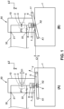
- Figure 1 schematically shows a switching device 50 for a medium-voltage electrical circuit 30.
- the switching device 50 comprises:
- the actuating lever 6 is movable between a first position called open position P1 in which the mobile electrode 4 and the fixed electrode 3 are separated by an open distance D1, and a second position called closed position P2 in which the mobile electrode 4 and the fixed electrode 3 are in contact so as to allow current to flow through the electrical circuit 30.
- a passage of the actuating lever 6 from the first position P1 to the second position P2 defines a displacement stroke C1.
- the displacement stroke C1 of the actuating lever 6 is greater than the open distance D1 such that the elastic member 5 is compressed when the actuating lever 5 passes from the first position P1 to the second position P2.
- the switching device 50 comprises at least one removable spacer 7 arranged between the frame 1 and the fixed electrode 3 so as to adjust the distance between the fixed electrode 3 and the frame 1 by removing the removable shim 7.
- the term "removable” is understood to mean that the switching device 50 is able to operate with the spacer 7 present in the switching device, or absent from the switching device.
- the removable spacer 7 may be mounted on the switching device 50, or removed from the switching device 50.
- the removable spacer 7 may be removed in a simple manner by an operator.
- the removable spacer 7 is a shim of a certain thickness.
- the removable spacer 7 adds to the distance between the fixed electrode 3 and the frame 1 along the displacement axis V of the mobile electrode 4.
- the removable spacer 7 is thus part of the chain of dimensions defining the open distance D1 between the mobile electrode 4 and the fixed electrode 3.
- the open distance D1 between the electrodes 3, 4 may thus be adjusted depending on whether the removable spacer 7 is present or absent, that is to say mounted or removed.
- the distance between the fixed electrode 3 and the frame 1 is less than when the removable spacer 7 is present, since the thickness e of the removable spacer 7 is no longer involved in the chain of dimensions between the fixed electrode 3 and the frame 1.
- the position of the mobile electrode 4 with respect to the frame 1 remains unchanged whether the removable spacer 7 is present or not.
- the open distance D1 between the electrodes 3, 4 decreases when the removable spacer 7 is removed.
- removing the spacer 7 counteracts the loss of contact overstroke originating in particular from the wear of the contacts of the electrodes 3, 4.
- the overstroke of the actuating lever 6 increases when the spacer 7 is removed, this making it possible to increase the contact pressure ensured by the elastic member 5.
- the service life of the switching device 50 may thus be prolonged by removing the removable spacer 7.
- the switching device 50 comprises a receiving enclosure 10 fixed to the frame 1.
- the receiving enclosure 10 is formed of an electrically insulating material.
- the receiving enclosure 10 is, for example, made of epoxy resin or of a thermoplastic material.
- the receiving enclosure 10 is commonly denoted by the term "pole”.
- the vacuum circuit breaker 2 is arranged in the receiving enclosure 10.
- the fixed electrode 3 is rigidly connected to the receiving enclosure 10.
- the body of the vacuum circuit breaker 2 is rigidly connected to the receiving enclosure 10.
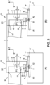
- Figure 2 illustrates the open distance between the electrodes 3, 4 depending on whether the removable spacer 7 is in a so-called mounted state or in a so-called removed state.
- “Mounted” state is understood to mean a state in which the removable spacer 7 is present in the switching device 50.
- Removed state is understood to mean a state in which the removable spacer 7 is absent from the switching device 50.
- the spacer 7 is present, and the open distance between the electrodes 3, 4 is indicated by the value D1.
- the thickness e of the spacer 7 has been exaggerated in order to improve the readability of the figure.
- the spacer 7 is not present.
- the position of the actuating lever 6 is unchanged between part A and part B, and corresponds to the open position P1.
- the open distance between the electrodes 3, 4 when the removable spacer is not present is indicated by the value D1'.
- This value D1' is less than the value D1, and differs from the value of the thickness e of the spacer 7.
- the dashed lines denoted by the signs h1, h2 respectively represent the position of the top of the enclosure 10 and the position of the fixed electrode 3 when the removable spacer 7 is mounted, as is the case in part A.
- the removable spacer 7 is mounted, as schematized in part A of figure 2 .
- the removable spacer 7 is removed so as to decrease the open distance D1 between the electrodes, as schematized in part B of figure 2 .
- the overstroke of the actuating lever 6 is thus increased, and consequently the contact pressure between the electrodes 3, 4 ensured by the elastic member 5.
- the removable spacer 7 is a shim of a certain thickness.
- the elastic member 5 exerts a repelling force between the mobile electrode 4 and the actuating lever 6.
- the elastic member 5 is prestressed.
- the elastic member 5 is in a compressed position when the fixed electrode 3 and the mobile electrode 4 are at a distance from one another.
- the stroke of the actuating lever 6 is fixed.
- the kinematics of the one or more actuators causing the movement of the actuating lever are not adjustable.
- the actuating lever 6 is in pivot connection with respect to the frame 1.
- the sign A1 illustrates the pivot axis of the actuating lever 6.
- the actuating lever 6 makes it possible to control the opening and the closing of the vacuum circuit breaker 2, and thus of the electrical circuit 30.
- the actuating lever 6 is mobile in rotation about an axis A1.
- a drive rod 17, secured to an actuator 18, passes through a portion of the actuating lever 6 in the opposite direction to the pivot axis A1, and may drive the actuating lever 6 to rotate.
- the arrow F schematically indicates the direction of the force applied by the actuator 18 when the vacuum circuit breaker 2 is being closed.
- the fixed electrode 3 is rigidly connected to the frame 1.
- the fixed electrode 3 and the mobile electrode 4 are coaxial.
- Each electrode 3, 4 comprises a disc-shaped electrical contact secured to a cylindrical rod.
- the electrical contacts of the two electrodes 3, 4 face one another.
- the disc-shaped portion of the mobile electrode 4 may come into contact with the disc-shaped portion of the fixed electrode 3, so as to allow electrical current to flow between the electrodes, and therefore through the vacuum circuit breaker 2 and the circuit 30.
- the mobile electrode 4 is mobile in translation along the shared axis of the electrodes. When the disc-shaped portion of the mobile electrode 4 is at a distance from the disc-shaped portion of the fixed electrode 3, the current is interrupted in the circuit 30.
- the switching device 50 comprises a device 20 for determining a difference between the displacement stroke C1 of the actuating lever 6 and the open distance D1 of the mobile electrode 4 with respect to the fixed electrode 3.
- the determined difference corresponds to the overstroke of the actuating lever 6.
- the actuating lever 6 is connected to the mobile electrode 4 via an insulator 8.
- the insulator 8 is arranged at least partly in the receiving enclosure 10.
- the insulator 8 is arranged entirely in the receiving enclosure 10.
- the actuating lever 6 is likewise connected to the mobile electrode 4 via a control plate 9 in pivot connection with the control lever 6.
- the sign A2 schematically illustrates the pivot axis of the control plate 9 with respect to the actuating lever 6.
- the elastic member 5 is arranged between the control plate 9 and the insulator 8.
- the insulator 8 is rigidly connected to the mobile electrode 4.
- the elastic member 5 is arranged between the insulator 8 and the mobile electrode 4.
- the control plate 9 is rigidly connected to the insulator 8.
- the pivot axis A1 of the control lever 6 with respect to the frame 1 and the pivot axis A2 of the control plate 9 with respect to the control lever 6 are parallel.
- the displacement stroke C1 of the actuating lever 6 is the stroke needed to displace the mobile electrode 4, that is to say the stroke of the control plate 9 along the direction of translation V of the mobile electrode 4.
- the device 20 for determining a difference between the displacement stroke C1 of the actuating lever 6 and the open distance D1 of the mobile electrode 4 comprises a position measurement device 19 which is set up to determine the relative position of the mobile electrode 4 with respect to the control plate 9.
- Part of the electrical circuit 30 is arranged in the enclosure 10.
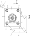
- the enclosure 10 one exemplary embodiment of which is shown in Figure 3 , has the general shape of a tube closed at one of its ends.
- the electrical conductors 21, 22 respectively connected to each electrode of the vacuum circuit breaker 2 each pass through the lateral wall of the tube.
- the open end of the tube faces the frame 1.
- the at least one removable spacer 7 is arranged between the receiving enclosure 10 and the frame 1. No modification to the frame 1 or to the receiving enclosure 10 is necessary in order to put the removable spacer 7 in place.
- the removable spacer 7 is made of metal here.
- the removable spacer 7 is, for example, made of stainless steel.
- the removable spacer 7 is planar.
- the removable spacer 7 is, for example, formed by cutting a metal sheet.
- the removable spacer 7 has a thickness e comprised between 0.5 millimetres and 2 millimetres.
- Figure 4 illustrates one exemplary embodiment of the switching device 50, wherein the at least one removable spacer 7 is arranged between a fixing flange 11, for fixing the receiving enclosure 10 to the frame, and the frame 1.
- a first face of the removable spacer 7 is in contact with the frame 1.
- a second face of the removable spacer 7, opposite to the first face, is in contact with the fixing flange 11.
- the removable spacer 7 is compressed between the fixing flange 11 and the frame 1 when the switching device 50 is in an operational state.
- Operational state is understood to mean a nominal operating state in which the various pieces are assembled and tightened at the nominal torque.
- the receiving enclosure 10 comprises a first portion 10a fixed to the frame 1 and a second portion 10b fixed to the first portion 10a, and the at least one removable spacer 7 is arranged between the first portion 10a and the second portion 10b of the receiving enclosure 10.
- the receiving enclosure is in two parts, and is formed by assembling the first portion 10a and the second portion 10b.
- a first face of the removable spacer 7 is in contact with the first portion 10a.
- a second face of the removable spacer 7, opposite to the first face, is in contact with the second portion 10b of the receiving enclosure 10.
- the removable spacer 7 is compressed between the first portion 10a and the second portion 10b when the switching device 50 is in an operational state.
- the dashed line denoted by the sign h3 represents the position of the upper edge of the first portion 10a of the enclosure 10 when the removable spacer 7 is mounted.
- the sign h4 represents the position of the fixed electrode 3 when the removable spacer 7 is mounted.
- the sign h5 represents the position of the upper edge of the second portion 10b. This position does not change between part A of Figure 9 , in which the spacer 7 is mounted, and part B in which the spacer 7 is removed.
- the displacement towards the bottom of the first portion 10a when the spacer 7 is removed causes the open distance of the electrodes to change from the distance D1 to the distance D1' which is less than D1.
- Figure 4 shows one exemplary embodiment.
- a lateral edge 15 of the removable spacer 7 is flush with a lateral edge 14 of the fixing flange 11.
- the fixing flange 11 of the receiving enclosure 10 has the general shape of a rectangle here.
- a lateral edge 15 of the removable spacer 7 protrudes from a lateral edge of the fixing flange 11.
- the at least one removable spacer 7 comprises a notch 12 for passage of a fixing means 13 for fixing the receiving enclosure 10 to the frame 1.
- the notch 12 extends along a direction transverse to a main axis X of the removable spacer 7.
- the spacer 7 may thus be put in place without completely removing the fixing means 13. It is enough to loosen the fixing means 13 in order to allow the insertion of the spacer 7 between the frame 1 and the fixing flange 11. In the same way, the spacer 7 may be withdrawn from the switching device 50 without removing the fixing means 13 by loosening them enough to allow the spacer 7 to be freed.
- the fixing flange 11 of the receiving enclosure 10 has a rectangular shape and comprises four fixing means 13 for fixing to the frame 1.
- Each fixing means 13 is arranged substantially at a corner of the rectangle defined by the fixing flange 11.
- the fixing means 13 are, for example, screws.
- the fixing flange 11 comprises four fixed inserts 16 in which the fixing screws 13 are received.
- the inserts 16 can be seen in Figure 4 , which is a transparent view.
- the spacer 7 may take various geometric shapes.
- the at least one removable spacer comprises a first plate 7a and a second plate 7b, each plate 7a, 7b comprising a first notch 12-1 for passage of a first fixing means 13 for fixing the receiving enclosure 10 to the frame 1 and a second notch 12-2 for passage of a second fixing means 13 for fixing the receiving enclosure 10 to the frame 1.
- the first plate 7a is arranged facing a first lateral edge of the fixing flange 11 and the second plate 7b is arranged facing a second lateral edge of the fixing flange 11.
- a spacer 7 comprising two plates 7a, 7b may be easily arranged and ensures a good contact surface with the frame 1, on the one hand, and with the fixing flange 11, on the other hand.
- the two plates 7a, 7b are, for example, planar.
- the two planar plates 7a, 7b are, for example, identical.
- Each plate 7a, 7b comprises a straight edge 15 which is set up to be flush with a lateral edge 14 of the fixing flange 11 when the plate 7a, 7b is present between the frame 1 and the receiving enclosure 10.
- the at least one removable spacer 7 comprises an L-shaped portion 7c, the L-shaped portion 7c comprising three notches 12 for passage of a fixing means 13.
- the at least one removable spacer 7 also comprises a U-shaped portion 7d.
- the portion 7d has the shape of an open ring allowing the passage of a fixing means 13.
- the direction D2 illustrates the direction in which the portion 7c is displaced so as to be inserted between the frame 1 and the fixing flange 11.
- the portion 7d may be inserted along a different direction of approach, since this portion 7d comprises a single passage notch.
- the spacer 7 is U-shaped and comprises two parallel branches connected by a base extending transversely across the branches.
- Each branch comprises a passage notch 12 for the passage of the fixing means 13.
- Each passage notch 12 extends parallel to the corresponding branch.
- the direction D3 schematizes the direction in which the spacer 7 is displaced so as to be inserted between the frame 1 and the fixing flange 11. The direction D3 coincides with the extension axis of each passage notch 12.
- the removable spacer 7 comprises four separate elements 7e.
- the at least one removable spacer 7 comprises a stack of at least two plates.
- two superposed spacers may be inserted.
- the second plate may also be removed, so as to compensate for a second level of loss of contact overstroke, greater than the first level.
- the operation of compensating for the wear and for the ageing may thus be carried out twice over the course of the life of the switching device, this making it possible to compensate for a larger amount of loss of contact overstroke.
- each switching device 50, 50', 50" comprises at least one removable spacer 7, 7', 7" which is separate from the at least one removable spacer of the other switching devices.
- each switching device 50, 50', 50" comprises its own removable spacer, or its own removable spacers, depending on the type of embodiment employed.
- the at least one removable spacer may be present for the switching device equipping one phase of the electrical circuit, and absent for the switching device equipping another phase of the electrical circuit.
- the electrical unit 100 comprises at least one removable spacer 7 which is shared by the three switching devices 50, 50', 50".
- one and the same removable spacer is arranged between the three switching devices 50, 50', 50".
- the removable spacer is thus simultaneously present for all the switching devices, or simultaneously absent for all the switching devices.
- the removable spacer may, for example, have a shape similar to the shape of part A of Figure 7 , repeated three times along a direction transverse to the direction D3.
Landscapes
- Driving Mechanisms And Operating Circuits Of Arc-Extinguishing High-Tension Switches (AREA)
- Scissors And Nippers (AREA)
Abstract
- a frame (1),
- a vacuum circuit breaker (2) comprising a fixed electrode (3) relative to the frame (1) and a mobile electrode (4),
- an elastic member (5),
- an actuating lever (6) connected to the mobile electrode (4) via the elastic member (5),
the actuating lever (6) being movable between an open position (P1) in which the electrodes (3,4) are separated by an open distance (D1), and a closed position (P2) in which the electrodes (3,4) are in contact,
a passage of the actuating lever (6) from the open position (P1) to the closed position (P2) defining a displacement stroke (C1), greater than the open distance (D1) such that the elastic member (5) is compressed when the actuating lever (6) passes from the first position (P1) to the second position (P2),
wherein the switching device (50) comprises at least one removable spacer (7) arranged between the frame (1) and the fixed electrode (3).
Description
- The present invention relates to the field of vacuum switching devices. These vacuum switching devices are, for example, used in medium-voltage, that is to say from 1 to 52 kV, electrical distribution units.
- These devices make it possible to close and to open each phase of the electrical circuit, and comprise vacuum circuit breakers, also called vacuum interrupters.
- The vacuum circuit breaker comprises a fixed electrode and a mobile electrode which is connected to a control lever. The control lever is mobile between two end positions defining a constant actuation stroke. By actuating the control lever, the mobile electrode is moved and may be separated from the fixed electrode or placed in contact with the latter, this opening or closing the electrical circuit.
- When the circuit is closed and the electrodes are in contact, sufficient contact pressure has to be ensured between the two electrodes, in order to resist the repelling forces present between them due to the flow of the current.
- To ensure this contact pressure, a spring is present in the kinematic linkage between the control lever and the mobile electrode, and the stroke of the control lever is greater than the minimum stroke for ensuring contact between the electrodes of the vacuum circuit breaker. The overstroke of the control lever therefore allows the spring to be compressed and a desired minimum contact pressure thus to be applied. The stroke required to obtain contact between the electrodes of the vacuum circuit breaker increases over time, due to the erosion of the contacts, the wear of the kinematic linkage and the creep of certain components arising over the use of the switching device. Consequently, the overstroke of the control lever decreases, that is to say that the compression of the spring creating the contact pressure created by the spring also decreases. The contact pressure between the electrodes therefore decreases over the life of the product.
- When the contact pressure between the electrodes becomes insufficient, operation of the switching device is no longer satisfactory. It then becomes necessary to carry out a major overhaul of the switching device in order to change the defective elements. This procedure is costly both in terms of material and intervention time. Furthermore, the device is unavailable for a significant amount of time.
- It is therefore desirable to have a solution making it possible to prolong the possible service life before a major overhaul of the switching device.
- To this end, the invention proposes a switching device for a medium-voltage electrical circuit, comprising:
- a frame,
- a vacuum circuit breaker comprising a fixed electrode relative to the frame and a mobile electrode,
- an elastic member,
- an actuating lever connected to the mobile electrode via the elastic member,
- the actuating lever being movable between a first position called open position in which the mobile electrode and the fixed electrode are separated by an open distance, and a second position called closed position in which the mobile electrode and the fixed electrode are in contact so as to allow current to flow through the electrical circuit,
- a passage of the actuating lever from the first position to the second position defining a displacement stroke,
- the displacement stroke of the actuating lever being greater than the open distance such that the elastic member is compressed when the actuating lever passes from the first position to the second position,
- wherein the switching device comprises at least one removable spacer arranged between the frame and the fixed electrode so as to adjust the distance between the fixed electrode and the frame by removing the removable shim.
- The removable spacer adds to the distance between the fixed electrode and the frame along the displacement axis of the mobile electrode.
- The removable spacer may be mounted on the switching device, or removed from the switching device. The removable spacer may be removed in a simple manner by an operator.
- The open distance between the electrodes may thus be adjusted depending on whether the removable spacer is mounted or removed. Specifically, when the removable spacer is not present, the distance between the fixed electrode and the frame is less than when the removable spacer is present, since the thickness of the removable spacer is no longer involved in the stack of dimensions between the fixed electrode and the frame. The position of the mobile electrode with respect to the frame remains unchanged whether the removable spacer is present or not. Thus, the open distance between the electrodes decreases when the removable spacer is removed. In other words, removing the spacer counteracts the loss of contact overstroke originating in particular from the wear of the contacts of the electrodes. The overstroke of the actuating lever increases, this making it possible to increase the contact pressure ensured by the elastic member. The service life of the switching device may thus be prolonged by removing the removable spacer.
- The features listed in the following paragraphs may be implemented independently of one another or in any technically possible combination:
According to one aspect of the switching device, the elastic member exerts a repelling force between the mobile electrode and the actuating lever. - The elastic member is prestressed.
- The stroke of the actuating lever is fixed.
- The actuating lever is in pivot connection with respect to the frame.
- The fixed electrode is rigidly connected to the frame.
- The fixed electrode and the mobile electrode are coaxial.
- The mobile electrode is mobile in translation along the shared axis of the electrodes.
- According to one embodiment, the switching device comprises a device for determining a difference between the displacement stroke of the actuating lever and the open distance of the mobile electrode with respect to the fixed electrode.
- By tracking the change in the overstroke of the actuating lever over time, it is possible to detect precisely at which point in time the removal of the removable spacer is opportune.
- According to one aspect of the switching device, the actuating lever is connected to the mobile electrode via an insulator.
- According to another aspect of the switching device, the actuating lever is connected to the mobile electrode via a control plate in pivot connection with the control lever.
- According to one embodiment of the switching device, the elastic member is arranged between the control plate and the insulator. The insulator is rigidly connected to the mobile electrode.
- According to another embodiment of the switching device, the elastic member is arranged between the insulator and the mobile electrode. The control plate is rigidly connected to the insulator.
- The pivot axis of the control lever with respect to the frame and the pivot axis of the control plate with respect to the control lever are parallel.
- The device for determining a difference between the displacement stroke of the actuating lever and the open distance of the mobile electrode comprises a position measurement device which is set up to determine the relative position of the mobile electrode with respect to the control plate.
- The switching device comprises a receiving enclosure fixed to the frame. The vacuum circuit breaker is arranged in the receiving enclosure. The fixed electrode is rigidly connected to the receiving enclosure.
- The receiving enclosure is formed of an electrically insulating material.
- The insulator is arranged at least partly in the receiving enclosure.
- The insulator is arranged entirely in the receiving enclosure.
- Part of the electrical circuit is arranged in the enclosure.
- According to one embodiment of the switching device, the at least one removable spacer is arranged between the receiving enclosure and the frame.
- No modification to the frame or to the receiving enclosure is necessary.
- The removable spacer is made of metal.
- The removable spacer is, for example, made of stainless steel.
- The removable spacer is planar.
- The removable spacer is formed by cutting a metal sheet.
- The removable spacer has a thickness comprised between 0.5 millimetres and 2 millimetres.
- According to one exemplary embodiment of the switching device, the at least one removable spacer is arranged between a fixing flange, for fixing the receiving enclosure to the frame, and the frame.
- A first face of the removable spacer is in contact with the frame. A second face of the removable spacer, opposite to the first face, is in contact with the fixing flange.
- The removable spacer is compressed between the fixing flange and the frame when the switching device is in an operational state.
- According to another exemplary embodiment of the switching device, the receiving enclosure comprises a first portion fixed to the frame and a second portion fixed to the first portion,
and the at least one removable spacer is arranged between the first portion and the second portion of the receiving enclosure. - In this case, a first face of the removable spacer is in contact with the first portion. A second face of the removable spacer, opposite to the first face, is in contact with the second portion of the receiving enclosure.
- The removable spacer is compressed between the first portion and the second portion when the switching device is in an operational state.
- According to one exemplary implementation of the switching device, a lateral edge of the removable spacer is flush with a lateral edge of the fixing flange.
- According to one embodiment variant, a lateral edge of the removable spacer protrudes from a lateral edge of the fixing flange.
- It is thus easy to check for the presence or absence of the removable spacer, since the lateral edge of the spacer protrudes beyond the fixing flange, or is flush with the latter. The edge of the spacer can therefore be easily seen by an operator when the spacer is present. Likewise, the absence of the spacer is easy to notice. Monitoring operations are thus made easier.
- According to one exemplary embodiment, the fixing flange of the receiving enclosure has the general shape of a rectangle.
- According to one embodiment of the switching device, the at least one removable spacer comprises a notch for passage of a fixing means for fixing the receiving enclosure to the frame.
- The notch extends along a direction transverse to a main axis of the removable spacer.
- The spacer may thus be put in place without completely removing the fixing means, which simply have to be loosened in order to allow the insertion of the spacer. In the same way, the spacer may be withdrawn without removing the fixing means.
- According to one exemplary embodiment, the fixing flange of the receiving enclosure has a rectangular shape and comprises four fixing means for fixing to the frame. Each fixing means is arranged substantially at a corner of the rectangle defined by the fixing flange.
- According to one embodiment of the switching device, the at least one removable spacer comprises a first plate and a second plate, each plate comprising a first notch for passage of a first fixing means for fixing the receiving enclosure to the frame and a second notch for passage of a second fixing means for fixing the receiving enclosure to the frame.
- The first plate is arranged facing a first lateral edge of the fixing flange and the second plate is arranged facing a second lateral edge of the fixing flange.
- When the fixing flange has a rectangular or square shape and comprises four fixing means, a spacer comprising two plates may be easily arranged and ensures a good contact surface with the frame, on the one hand, and with the fixing flange, on the other hand.
- The two plates are, for example, planar.
- The two planar plates are, for example, identical.
- Each plate comprises a straight edge which is set up to be flush with a lateral edge of the fixing flange when the plate is present between the frame and the receiving enclosure.
- According to one embodiment, the at least one removable spacer comprises an L-shaped portion, the L-shaped portion comprising three notches for passage of a fixing means.
- According to one embodiment, the at least one removable spacer comprises a U-shaped portion.
- According to another embodiment variant, the at least one removable spacer is U-shaped and comprises two parallel branches connected by a base extending transversely across the branches, each branch comprising a passage notch for the passage of the fixing means.
- According to one embodiment of the switching device, the at least one removable spacer comprises a stack of at least two plate.
- The removable spacer comprises two superposed, that is to say stacked, plates. In this case, it is possible, over the course of the life of the switching device, to remove a first plate so as to compensate for a first level of loss of overstroke of the contacts of the electrodes. Later, the second plate is removed in turn, so as to compensate for a second level of loss of contact overstroke. The operation of compensating for the wear may thus be carried out twice, this making it possible to compensate for a larger amount of loss of contact overstroke.
- The disclosure likewise relates to a three-phase medium-voltage electrical unit, comprising for each phase a switching device as described above.
- According to one embodiment of the electrical unit, each switching device comprises at least one removable spacer which is separate from the at least one removable spacer of the other switching devices.
- According to another embodiment, the electrical unit comprises at least one removable spacer which is shared by the three switching devices.
- Further features, details and advantages will become apparent from reading the following detailed description and from studying the attached drawings in which:
- [
Fig. 1 ] is a basic diagram illustrating the operation of a switching device according to a first embodiment, - [
Fig. 2 ] is another basic diagram of a switching device according to the first embodiment, - [
Fig. 3 ] is a perspective partial view of an electrical unit comprising a switching device, - [
Fig. 4 ] is another perspective partial view of an electrical unit comprising a switching device according to the first embodiment, - [
Fig. 5 ] is a perspective view of one embodiment of a removable spacer which may be integrated into the switching device offigure 4 , - [
Fig. 6 ] is a partial view, from below, of a switching device comprising a removable spacer according to one embodiment variant, - [
Fig. 7 ] is a plan view of another embodiment variant of a removable spacer which may be integrated into the proposed switching device, - [
Fig. 8 ] is a partial view, in cross section, of the electrical unit offigures 3 and4 , - [
Fig. 9 ] is a basic diagram of a switching device according to a second embodiment. - To make the figures easier to read, the various elements are not necessarily drawn to scale. In these figures, elements that are identical bear the same references. Certain elements or parameters may be indexed, that is to say designated for example by first element or second element, or even first parameter and second parameter, etc. The aim of this indexing is to differentiate between elements or parameters that are similar but not identical. This indexing does not imply that one element or parameter takes priority over another, and the denominations may be interchanged. Where it is specified that a subsystem comprises a given element, that does not exclude there being other elements present in that subsystem. Similarly, when it is specified that a subsystem comprises a given element, it is understood that the subsystem comprises at least this element.
-
Figure 8 shows a three-phase medium-voltageelectrical unit 100. Medium voltage is understood to mean a voltage of between 1 kV and 52 kV. - The
electrical unit 100 comprises for each phase aswitching device -
Figure 1 schematically shows aswitching device 50 for a medium-voltageelectrical circuit 30. - The switching
device 50 comprises: - a
frame 1, - a
vacuum circuit breaker 2 comprising a fixedelectrode 3 relative to theframe 1 and amobile electrode 4, - an
elastic member 5, - an
actuating lever 6 connected to themobile electrode 4 via theelastic member 5. - The
actuating lever 6 is movable between a first position called open position P1 in which themobile electrode 4 and the fixedelectrode 3 are separated by an open distance D1, and a second position called closed position P2 in which themobile electrode 4 and the fixedelectrode 3 are in contact so as to allow current to flow through theelectrical circuit 30. - A passage of the
actuating lever 6 from the first position P1 to the second position P2 defines a displacement stroke C1. - The displacement stroke C1 of the
actuating lever 6 is greater than the open distance D1 such that theelastic member 5 is compressed when theactuating lever 5 passes from the first position P1 to the second position P2. - The switching
device 50 comprises at least oneremovable spacer 7 arranged between theframe 1 and the fixedelectrode 3 so as to adjust the distance between the fixedelectrode 3 and theframe 1 by removing theremovable shim 7. - The term "removable" is understood to mean that the switching
device 50 is able to operate with thespacer 7 present in the switching device, or absent from the switching device. - In other words, the
removable spacer 7 may be mounted on theswitching device 50, or removed from the switchingdevice 50. Theremovable spacer 7 may be removed in a simple manner by an operator. - The
removable spacer 7 is a shim of a certain thickness. - In the sense of the present patent application, the terms "removable shim" and "removable spacer" are equivalent.
- The
removable spacer 7 adds to the distance between the fixedelectrode 3 and theframe 1 along the displacement axis V of themobile electrode 4. - The
removable spacer 7 is thus part of the chain of dimensions defining the open distance D1 between themobile electrode 4 and the fixedelectrode 3. - The open distance D1 between the
electrodes removable spacer 7 is present or absent, that is to say mounted or removed. - Specifically, when the
removable spacer 7 is not present, the distance between the fixedelectrode 3 and theframe 1 is less than when theremovable spacer 7 is present, since the thickness e of theremovable spacer 7 is no longer involved in the chain of dimensions between the fixedelectrode 3 and theframe 1. The position of themobile electrode 4 with respect to theframe 1 remains unchanged whether theremovable spacer 7 is present or not. Thus, the open distance D1 between theelectrodes removable spacer 7 is removed. In other words, removing thespacer 7 counteracts the loss of contact overstroke originating in particular from the wear of the contacts of theelectrodes actuating lever 6 increases when thespacer 7 is removed, this making it possible to increase the contact pressure ensured by theelastic member 5. The service life of theswitching device 50 may thus be prolonged by removing theremovable spacer 7. - The switching
device 50 comprises a receivingenclosure 10 fixed to theframe 1. The receivingenclosure 10 is formed of an electrically insulating material. - The receiving
enclosure 10 is, for example, made of epoxy resin or of a thermoplastic material. - The receiving
enclosure 10 is commonly denoted by the term "pole". - The
vacuum circuit breaker 2 is arranged in the receivingenclosure 10. The fixedelectrode 3 is rigidly connected to the receivingenclosure 10. - Likewise, the body of the
vacuum circuit breaker 2 is rigidly connected to the receivingenclosure 10. -
Figure 2 illustrates the open distance between theelectrodes removable spacer 7 is in a so-called mounted state or in a so-called removed state. - "Mounted" state is understood to mean a state in which the
removable spacer 7 is present in theswitching device 50. - "Removed" state is understood to mean a state in which the
removable spacer 7 is absent from the switchingdevice 50. - In part A of
figure 2 , thespacer 7 is present, and the open distance between theelectrodes spacer 7 has been exaggerated in order to improve the readability of the figure. - In part B of
figure 2 , thespacer 7 is not present. - The position of the
actuating lever 6 is unchanged between part A and part B, and corresponds to the open position P1. - The open distance between the
electrodes spacer 7. - The dashed lines denoted by the signs h1, h2 respectively represent the position of the top of the
enclosure 10 and the position of the fixedelectrode 3 when theremovable spacer 7 is mounted, as is the case in part A. - The natural elasticity of the conductive bar connected to the
lower contact 22, symbolized by the wave shape, makes it possible to compensate for the change in the position of theenclosure 10 when thespacer 7 is removed. - In the new state of the
switching device 50, theremovable spacer 7 is mounted, as schematized in part A offigure 2 . Over the course of the use of theswitching device 50, when the monitoring operations carried out show that the loss of contact overstroke has reached a certain threshold, theremovable spacer 7 is removed so as to decrease the open distance D1 between the electrodes, as schematized in part B offigure 2 . The overstroke of theactuating lever 6 is thus increased, and consequently the contact pressure between theelectrodes elastic member 5. - The
removable spacer 7 is a shim of a certain thickness. - The
elastic member 5 exerts a repelling force between themobile electrode 4 and theactuating lever 6. - The
elastic member 5 is prestressed. - In other words, the
elastic member 5 is in a compressed position when the fixedelectrode 3 and themobile electrode 4 are at a distance from one another. - The more the
elastic member 5 is compressed, the more the stored potential energy increases. - The stroke of the
actuating lever 6 is fixed. - In other words, the kinematics of the one or more actuators causing the movement of the actuating lever are not adjustable.
- The
actuating lever 6 is in pivot connection with respect to theframe 1. The sign A1 illustrates the pivot axis of theactuating lever 6. - The
actuating lever 6 makes it possible to control the opening and the closing of thevacuum circuit breaker 2, and thus of theelectrical circuit 30. Theactuating lever 6 is mobile in rotation about an axis A1. - As can be seen in
Figure 8 , adrive rod 17, secured to anactuator 18, passes through a portion of theactuating lever 6 in the opposite direction to the pivot axis A1, and may drive the actuatinglever 6 to rotate. The arrow F schematically indicates the direction of the force applied by theactuator 18 when thevacuum circuit breaker 2 is being closed. - The fixed
electrode 3 is rigidly connected to theframe 1. - The fixed
electrode 3 and themobile electrode 4 are coaxial. - Each
electrode electrodes - The disc-shaped portion of the
mobile electrode 4 may come into contact with the disc-shaped portion of the fixedelectrode 3, so as to allow electrical current to flow between the electrodes, and therefore through thevacuum circuit breaker 2 and thecircuit 30. - The
mobile electrode 4 is mobile in translation along the shared axis of the electrodes. When the disc-shaped portion of themobile electrode 4 is at a distance from the disc-shaped portion of the fixedelectrode 3, the current is interrupted in thecircuit 30. - According to the illustrated example, the switching
device 50 comprises adevice 20 for determining a difference between the displacement stroke C1 of theactuating lever 6 and the open distance D1 of themobile electrode 4 with respect to the fixedelectrode 3. - The determined difference corresponds to the overstroke of the
actuating lever 6. By tracking the change in the overstroke of theactuating lever 6 over time, it is possible to detect precisely at which point in time the removal of theremovable spacer 7 is opportune. - The
actuating lever 6 is connected to themobile electrode 4 via aninsulator 8. Theinsulator 8 is arranged at least partly in the receivingenclosure 10. - Preferably, the
insulator 8 is arranged entirely in the receivingenclosure 10. - The
actuating lever 6 is likewise connected to themobile electrode 4 via acontrol plate 9 in pivot connection with thecontrol lever 6. - The sign A2 schematically illustrates the pivot axis of the
control plate 9 with respect to theactuating lever 6. - According to the illustrated example, the
elastic member 5 is arranged between thecontrol plate 9 and theinsulator 8. Theinsulator 8 is rigidly connected to themobile electrode 4. - According to another embodiment of the
switching device 50, not illustrated, theelastic member 5 is arranged between theinsulator 8 and themobile electrode 4. Thecontrol plate 9 is rigidly connected to theinsulator 8. - The pivot axis A1 of the
control lever 6 with respect to theframe 1 and the pivot axis A2 of thecontrol plate 9 with respect to thecontrol lever 6 are parallel. - The displacement stroke C1 of the
actuating lever 6 is the stroke needed to displace themobile electrode 4, that is to say the stroke of thecontrol plate 9 along the direction of translation V of themobile electrode 4. - The
device 20 for determining a difference between the displacement stroke C1 of theactuating lever 6 and the open distance D1 of themobile electrode 4 comprises aposition measurement device 19 which is set up to determine the relative position of themobile electrode 4 with respect to thecontrol plate 9. - Various embodiments are possible for the
device 20 and theposition measurement device 19, and will not be described in detail. - Part of the
electrical circuit 30 is arranged in theenclosure 10. - The
enclosure 10, one exemplary embodiment of which is shown inFigure 3 , has the general shape of a tube closed at one of its ends. - The
electrical conductors vacuum circuit breaker 2 each pass through the lateral wall of the tube. - The connection between this lateral wall and each electrical conductor is tight.
- The open end of the tube faces the
frame 1. - According to one embodiment of the
switching device 50, the at least oneremovable spacer 7 is arranged between the receivingenclosure 10 and theframe 1. No modification to theframe 1 or to the receivingenclosure 10 is necessary in order to put theremovable spacer 7 in place. - This setup is that illustrated in
Figures 1 and2 . - The
removable spacer 7 is made of metal here. - The
removable spacer 7 is, for example, made of stainless steel. - The
removable spacer 7 is planar. - The
removable spacer 7 is, for example, formed by cutting a metal sheet. - The
removable spacer 7 has a thickness e comprised between 0.5 millimetres and 2 millimetres. -
Figure 4 illustrates one exemplary embodiment of theswitching device 50, wherein the at least oneremovable spacer 7 is arranged between a fixingflange 11, for fixing the receivingenclosure 10 to the frame, and theframe 1. - A first face of the
removable spacer 7 is in contact with theframe 1. A second face of theremovable spacer 7, opposite to the first face, is in contact with the fixingflange 11. - The
removable spacer 7 is compressed between the fixingflange 11 and theframe 1 when theswitching device 50 is in an operational state. - Operational state is understood to mean a nominal operating state in which the various pieces are assembled and tightened at the nominal torque.
- According to another embodiment of the
switching device 50, illustrated inFigure 9 , the receivingenclosure 10 comprises afirst portion 10a fixed to theframe 1 and asecond portion 10b fixed to thefirst portion 10a,
and the at least oneremovable spacer 7 is arranged between thefirst portion 10a and thesecond portion 10b of the receivingenclosure 10. - The receiving enclosure is in two parts, and is formed by assembling the
first portion 10a and thesecond portion 10b. A first face of theremovable spacer 7 is in contact with thefirst portion 10a. A second face of theremovable spacer 7, opposite to the first face, is in contact with thesecond portion 10b of the receivingenclosure 10. Theremovable spacer 7 is compressed between thefirst portion 10a and thesecond portion 10b when theswitching device 50 is in an operational state. - In
Figure 9 , the dashed line denoted by the sign h3 represents the position of the upper edge of thefirst portion 10a of theenclosure 10 when theremovable spacer 7 is mounted. The sign h4 represents the position of the fixedelectrode 3 when theremovable spacer 7 is mounted. The sign h5 represents the position of the upper edge of thesecond portion 10b. This position does not change between part A ofFigure 9 , in which thespacer 7 is mounted, and part B in which thespacer 7 is removed. - The displacement towards the bottom of the
first portion 10a when thespacer 7 is removed causes the open distance of the electrodes to change from the distance D1 to the distance D1' which is less than D1. -
Figure 4 shows one exemplary embodiment. - According to the example of
Figure 4 , alateral edge 15 of theremovable spacer 7 is flush with alateral edge 14 of the fixingflange 11. - The fixing
flange 11 of the receivingenclosure 10 has the general shape of a rectangle here. - According to one embodiment variant, not shown, a
lateral edge 15 of theremovable spacer 7 protrudes from a lateral edge of the fixingflange 11. - It is thus easy to check for the presence or absence of the
removable spacer 7, since thelateral edge 15 of thespacer 7 protrudes beyond the fixingflange 11, or is flush with the latter. The edge of thespacer 7 can therefore be easily seen by an operator when thespacer 7 is present. In the same way, the absence of thespacer 7 is easy to notice. Monitoring operations are thus made easier. - The at least one
removable spacer 7 comprises anotch 12 for passage of a fixing means 13 for fixing the receivingenclosure 10 to theframe 1. - The
notch 12 extends along a direction transverse to a main axis X of theremovable spacer 7. - The
spacer 7 may thus be put in place without completely removing the fixing means 13. It is enough to loosen the fixing means 13 in order to allow the insertion of thespacer 7 between theframe 1 and the fixingflange 11. In the same way, thespacer 7 may be withdrawn from the switchingdevice 50 without removing the fixing means 13 by loosening them enough to allow thespacer 7 to be freed. - According to the example of
Figures 3 and4 , the fixingflange 11 of the receivingenclosure 10 has a rectangular shape and comprises four fixing means 13 for fixing to theframe 1. Each fixing means 13 is arranged substantially at a corner of the rectangle defined by the fixingflange 11. - The fixing means 13 are, for example, screws.
- Here, the fixing
flange 11 comprises four fixedinserts 16 in which the fixing screws 13 are received. Theinserts 16 can be seen inFigure 4 , which is a transparent view. - The
spacer 7 may take various geometric shapes. - According to the embodiment of
Figure 4 and ofFigure 5 , the at least one removable spacer comprises afirst plate 7a and asecond plate 7b, eachplate enclosure 10 to theframe 1 and a second notch 12-2 for passage of a second fixing means 13 for fixing the receivingenclosure 10 to theframe 1. - The
first plate 7a is arranged facing a first lateral edge of the fixingflange 11 and thesecond plate 7b is arranged facing a second lateral edge of the fixingflange 11. - When the fixing
flange 11 has a rectangular or square shape and comprises four fixing means 13, aspacer 7 comprising twoplates frame 1, on the one hand, and with the fixingflange 11, on the other hand. - The two
plates - The two
planar plates - Each
plate straight edge 15 which is set up to be flush with alateral edge 14 of the fixingflange 11 when theplate frame 1 and the receivingenclosure 10. - According to another embodiment variant, illustrated in
Figure 6 , the at least oneremovable spacer 7 comprises an L-shapedportion 7c, the L-shapedportion 7c comprising threenotches 12 for passage of a fixing means 13. - The at least one
removable spacer 7 also comprises aU-shaped portion 7d. Theportion 7d has the shape of an open ring allowing the passage of a fixing means 13. - In
Figure 6 , the direction D2 illustrates the direction in which theportion 7c is displaced so as to be inserted between theframe 1 and the fixingflange 11. - The
portion 7d may be inserted along a different direction of approach, since thisportion 7d comprises a single passage notch. - According to another embodiment variant, illustrated in part A of
Figure 7 , thespacer 7 is U-shaped and comprises two parallel branches connected by a base extending transversely across the branches. - Each branch comprises a
passage notch 12 for the passage of the fixing means 13. Eachpassage notch 12 extends parallel to the corresponding branch. The direction D3 schematizes the direction in which thespacer 7 is displaced so as to be inserted between theframe 1 and the fixingflange 11. The direction D3 coincides with the extension axis of eachpassage notch 12. - The position of these fixing means is schematized by the dashed circles denoted by the
sign 13. - According to yet another embodiment variant, illustrated in part B of
Figure 7 , theremovable spacer 7 comprises fourseparate elements 7e. - According to one embodiment of the
switching device 50, not shown, the at least oneremovable spacer 7 comprises a stack of at least two plates. - In other words, two superposed spacers may be inserted.
- In this case, it is possible, over the course of the life of the
switching device 50, to remove a first plate so as to compensate for a first level of loss of overstroke of the contacts of theelectrodes - Later in the life of the
switching device 50, the second plate may also be removed, so as to compensate for a second level of loss of contact overstroke, greater than the first level. - The operation of compensating for the wear and for the ageing may thus be carried out twice over the course of the life of the switching device, this making it possible to compensate for a larger amount of loss of contact overstroke.
- According to one embodiment of the
electrical unit 100, each switchingdevice removable spacer - In other words, each switching
device - According to another embodiment, the
electrical unit 100 comprises at least oneremovable spacer 7 which is shared by the threeswitching devices - In this case, one and the same removable spacer is arranged between the three
switching devices - The removable spacer is thus simultaneously present for all the switching devices, or simultaneously absent for all the switching devices.
- The removable spacer may, for example, have a shape similar to the shape of part A of
Figure 7 , repeated three times along a direction transverse to the direction D3.
Claims (13)
- Switching device (50) for a medium-voltage electrical circuit (30), comprising:- a frame (1),- a vacuum circuit breaker (2) comprising a fixed electrode (3) relative to the frame (1) and a mobile electrode (4),- an elastic member (5),- an actuating lever (6) connected to the mobile electrode (4) via the elastic member (5),the actuating lever (6) being movable between a first position called open position (P1) in which the mobile electrode (4) and the fixed electrode (3) are separated by an open distance (D1), and a second position called closed position (P2) in which the mobile electrode (4) and the fixed electrode (3) are in contact so as to allow current to flow through the electrical circuit (30),a passage of the actuating lever (6) from the first position (P1) to the second position (P2) defining a displacement stroke (C1),the displacement stroke (C1) of the actuating lever (6) being greater than the open distance (D1) such that the elastic member (5) is compressed when the actuating lever (6) passes from the first position (P1) to the second position (P2),wherein the switching device (50) comprises at least one removable spacer (7) arranged between the frame (1) and the fixed electrode (3) so as to adjust the distance between the fixed electrode (3) and the frame (1) by removing the removable spacer (7).
- Switching device (50) according to Claim 1, comprising a device (20) for determining a difference (d) between the displacement stroke (C1) of the actuating lever (6) and the open distance (D1) of the mobile electrode (4) with respect to the fixed electrode (3).
- Switching device (50) according to Claim 1 or 2, wherein the actuating lever (6) is connected to the mobile electrode (4) via an insulator (8),
and wherein the actuating lever (6) is connected to the mobile electrode (4) via a control plate (9) in pivot connection with the control lever (6). - Switching device (50) according to one of the preceding claims, comprising a receiving enclosure (10) fixed to the frame (1), wherein the vacuum circuit breaker (2) is arranged in the receiving enclosure (10), and wherein the fixed electrode (3) is rigidly connected to the receiving enclosure (10).
- Switching device (50) according to the preceding claim, wherein the at least one removable spacer (7) is arranged between the receiving enclosure (10) and the frame (1).
- Switching device (50) according to Claim 4 or 5, wherein the at least one removable spacer (7) is arranged between a fixing flange (11), for fixing the receiving enclosure (10) to the frame (1), and the frame (1).
- Switching device (50) according to either of Claims 4 and 5, wherein the receiving enclosure (10) comprises a first portion (10a) fixed to the frame (1) and a second portion (10b) fixed to the first portion (10a),
and wherein the at least one removable spacer (7) is arranged between the first portion (10a) and the second portion (10b) of the receiving enclosure (10). - Switching device (50) according to one of Claims 4 to 7, wherein the at least one removable spacer (7) comprises a notch (12) for passage of a fixing means (13) for fixing the receiving enclosure (10) to the frame (1).
- Switching device (50) according to one of Claims 4 to 8, wherein the at least one removable spacer comprises a first plate (7a) and a second plate (7b), each plate (7a, 7b) comprising a first notch (16a) for passage of a first fixing means (13) for fixing the receiving enclosure (10) to the frame (1) and a second notch (16b) for passage of a second fixing means (13) for fixing the receiving enclosure (10) to the frame (1).
- Switching device (50) according to one of the preceding claims, wherein the at least one removable spacer (7) comprises a stack of at least two plates.
- Three-phase medium-voltage electrical unit (100), comprising for each phase a switching device (50, 50', 50") according to one of the preceding claims.
- Electrical unit (100) according to the preceding claim, wherein each switching device (50, 50', 50") comprises at least one removable spacer (7, 7', 7") which is separate from the at least one removable spacer of the other switching devices.
- Electrical unit (100) according to Claim 11 or 12, comprising at least one removable spacer (7) which is shared by the three switching devices (50, 50', 50").
Applications Claiming Priority (1)
| Application Number | Priority Date | Filing Date | Title |
|---|---|---|---|
| FR2303987A FR3148116A1 (en) | 2023-04-20 | 2023-04-20 | Device for cutting off a medium voltage electrical circuit |
Publications (3)
| Publication Number | Publication Date |
|---|---|
| EP4451302A1 true EP4451302A1 (en) | 2024-10-23 |
| EP4451302B1 EP4451302B1 (en) | 2025-07-30 |
| EP4451302C0 EP4451302C0 (en) | 2025-07-30 |
Family
ID=87036812
Family Applications (1)
| Application Number | Title | Priority Date | Filing Date |
|---|---|---|---|
| EP24169373.8A Active EP4451302B1 (en) | 2023-04-20 | 2024-04-10 | Switching device for a medium-voltage electrical circuit |
Country Status (4)
| Country | Link |
|---|---|
| US (1) | US20240355563A1 (en) |
| EP (1) | EP4451302B1 (en) |
| CN (1) | CN118824780A (en) |
| FR (1) | FR3148116A1 (en) |
Citations (2)
| Publication number | Priority date | Publication date | Assignee | Title |
|---|---|---|---|---|
| FR2827075A1 (en) * | 2001-07-05 | 2003-01-10 | Schneider Electric Ind Sa | ELECTRICAL CUT-OFF AND SECTIONING APPARATUS HAVING A VACUUM BULB |
| US9305725B2 (en) * | 2012-11-21 | 2016-04-05 | Mitsubishi Electric Corporation | Switching apparatus |
-
2023
- 2023-04-20 FR FR2303987A patent/FR3148116A1/en not_active Ceased
-
2024
- 2024-04-08 US US18/628,946 patent/US20240355563A1/en active Pending
- 2024-04-10 EP EP24169373.8A patent/EP4451302B1/en active Active
- 2024-04-19 CN CN202410476550.4A patent/CN118824780A/en active Pending
Patent Citations (2)
| Publication number | Priority date | Publication date | Assignee | Title |
|---|---|---|---|---|
| FR2827075A1 (en) * | 2001-07-05 | 2003-01-10 | Schneider Electric Ind Sa | ELECTRICAL CUT-OFF AND SECTIONING APPARATUS HAVING A VACUUM BULB |
| US9305725B2 (en) * | 2012-11-21 | 2016-04-05 | Mitsubishi Electric Corporation | Switching apparatus |
Also Published As
| Publication number | Publication date |
|---|---|
| EP4451302B1 (en) | 2025-07-30 |
| CN118824780A (en) | 2024-10-22 |
| US20240355563A1 (en) | 2024-10-24 |
| EP4451302C0 (en) | 2025-07-30 |
| FR3148116A1 (en) | 2024-10-25 |
Similar Documents
| Publication | Publication Date | Title |
|---|---|---|
| JP5235620B2 (en) | Vacuum switchgear | |
| CN1808660B (en) | Apparatus and method for use in a circuit interrupter | |
| US7417846B2 (en) | Gas-insulated switchgear | |
| JP4866949B2 (en) | Vacuum insulated switchgear | |
| US8710388B2 (en) | Switchgear and method for operating switchgear | |
| EP2073331A2 (en) | Vacuum insulated switchgear | |
| EP1858044A2 (en) | Switchgear | |
| EP4451302B1 (en) | Switching device for a medium-voltage electrical circuit | |
| WO2001086675A2 (en) | Flexible shunt for electric power switch | |
| KR100972266B1 (en) | Vacuum switch gear | |
| CN101901716A (en) | switchgear | |
| CN108292571B (en) | Gas-insulated medium-voltage switchgear assembly with circuit breaker pole part arrangement | |
| JP4439035B2 (en) | Gas-filled switchgear | |
| Slade et al. | The effect of contact closure in vacuum with fault current on prestrike arcing time, contact welding and the field enhancement factor | |
| CN114113946A (en) | Sectional voltage-withstanding test equipment | |
| EP4589621A1 (en) | Guiding parts for vacuum circuit breaker | |
| EP2034501A1 (en) | Quickly exchangeable switching device in fixed type medium voltage switchgear system | |
| CN100568434C (en) | Multi circuit selecting switchgear | |
| JP4236838B2 (en) | Switchgear | |
| US11908646B2 (en) | Breaking device for a medium voltage electrical circuit | |
| EP4432324B1 (en) | Switchgear architecture | |
| EP0149491B1 (en) | Earthing switch for gas-insulated switchgear apparatus | |
| JPS61121222A (en) | Compound type switchgear | |
| JPH07296686A (en) | Insulation rod for vacuum switchgear | |
| JPH0877887A (en) | Disconnector with resistance |
Legal Events
| Date | Code | Title | Description |
|---|---|---|---|
| PUAI | Public reference made under article 153(3) epc to a published international application that has entered the european phase |
Free format text: ORIGINAL CODE: 0009012 |
|
| STAA | Information on the status of an ep patent application or granted ep patent |
Free format text: STATUS: THE APPLICATION HAS BEEN PUBLISHED |
|
| AK | Designated contracting states |
Kind code of ref document: A1 Designated state(s): AL AT BE BG CH CY CZ DE DK EE ES FI FR GB GR HR HU IE IS IT LI LT LU LV MC ME MK MT NL NO PL PT RO RS SE SI SK SM TR |
|
| STAA | Information on the status of an ep patent application or granted ep patent |
Free format text: STATUS: REQUEST FOR EXAMINATION WAS MADE |
|
| GRAP | Despatch of communication of intention to grant a patent |
Free format text: ORIGINAL CODE: EPIDOSNIGR1 |
|
| STAA | Information on the status of an ep patent application or granted ep patent |
Free format text: STATUS: GRANT OF PATENT IS INTENDED |
|
| 17P | Request for examination filed |
Effective date: 20250213 |
|
| RIC1 | Information provided on ipc code assigned before grant |
Ipc: H01H 11/00 20060101ALN20250221BHEP Ipc: H01H 3/32 20060101ALN20250221BHEP Ipc: H01H 33/666 20060101ALN20250221BHEP Ipc: H01H 33/664 20060101ALI20250221BHEP Ipc: H01H 1/50 20060101AFI20250221BHEP |
|
| INTG | Intention to grant announced |
Effective date: 20250312 |
|
| GRAS | Grant fee paid |
Free format text: ORIGINAL CODE: EPIDOSNIGR3 |
|
| GRAA | (expected) grant |
Free format text: ORIGINAL CODE: 0009210 |
|
| STAA | Information on the status of an ep patent application or granted ep patent |
Free format text: STATUS: THE PATENT HAS BEEN GRANTED |
|
| AK | Designated contracting states |
Kind code of ref document: B1 Designated state(s): AL AT BE BG CH CY CZ DE DK EE ES FI FR GB GR HR HU IE IS IT LI LT LU LV MC ME MK MT NL NO PL PT RO RS SE SI SK SM TR |
|
| REG | Reference to a national code |
Ref country code: GB Ref legal event code: FG4D |
|
| REG | Reference to a national code |
Ref country code: CH Ref legal event code: EP |
|
| REG | Reference to a national code |
Ref country code: DE Ref legal event code: R096 Ref document number: 602024000354 Country of ref document: DE |
|
| REG | Reference to a national code |
Ref country code: IE Ref legal event code: FG4D |
|
| U01 | Request for unitary effect filed |
Effective date: 20250825 |
|
| U07 | Unitary effect registered |
Designated state(s): AT BE BG DE DK EE FI FR IT LT LU LV MT NL PT RO SE SI Effective date: 20250901 |
|
| PG25 | Lapsed in a contracting state [announced via postgrant information from national office to epo] |
Ref country code: IS Free format text: LAPSE BECAUSE OF FAILURE TO SUBMIT A TRANSLATION OF THE DESCRIPTION OR TO PAY THE FEE WITHIN THE PRESCRIBED TIME-LIMIT Effective date: 20251130 |
|
| PG25 | Lapsed in a contracting state [announced via postgrant information from national office to epo] |
Ref country code: NO Free format text: LAPSE BECAUSE OF FAILURE TO SUBMIT A TRANSLATION OF THE DESCRIPTION OR TO PAY THE FEE WITHIN THE PRESCRIBED TIME-LIMIT Effective date: 20251030 |
|
| PG25 | Lapsed in a contracting state [announced via postgrant information from national office to epo] |
Ref country code: HR Free format text: LAPSE BECAUSE OF FAILURE TO SUBMIT A TRANSLATION OF THE DESCRIPTION OR TO PAY THE FEE WITHIN THE PRESCRIBED TIME-LIMIT Effective date: 20250730 |
|
| PG25 | Lapsed in a contracting state [announced via postgrant information from national office to epo] |
Ref country code: GR Free format text: LAPSE BECAUSE OF FAILURE TO SUBMIT A TRANSLATION OF THE DESCRIPTION OR TO PAY THE FEE WITHIN THE PRESCRIBED TIME-LIMIT Effective date: 20251031 |
|
| PG25 | Lapsed in a contracting state [announced via postgrant information from national office to epo] |
Ref country code: PL Free format text: LAPSE BECAUSE OF FAILURE TO SUBMIT A TRANSLATION OF THE DESCRIPTION OR TO PAY THE FEE WITHIN THE PRESCRIBED TIME-LIMIT Effective date: 20250730 |
|
| PG25 | Lapsed in a contracting state [announced via postgrant information from national office to epo] |
Ref country code: RS Free format text: LAPSE BECAUSE OF FAILURE TO SUBMIT A TRANSLATION OF THE DESCRIPTION OR TO PAY THE FEE WITHIN THE PRESCRIBED TIME-LIMIT Effective date: 20251030 |
|
| PG25 | Lapsed in a contracting state [announced via postgrant information from national office to epo] |
Ref country code: ES Free format text: LAPSE BECAUSE OF FAILURE TO SUBMIT A TRANSLATION OF THE DESCRIPTION OR TO PAY THE FEE WITHIN THE PRESCRIBED TIME-LIMIT Effective date: 20250730 |
|
| PG25 | Lapsed in a contracting state [announced via postgrant information from national office to epo] |
Ref country code: SM Free format text: LAPSE BECAUSE OF FAILURE TO SUBMIT A TRANSLATION OF THE DESCRIPTION OR TO PAY THE FEE WITHIN THE PRESCRIBED TIME-LIMIT Effective date: 20250730 |
|
| PG25 | Lapsed in a contracting state [announced via postgrant information from national office to epo] |
Ref country code: CZ Free format text: LAPSE BECAUSE OF FAILURE TO SUBMIT A TRANSLATION OF THE DESCRIPTION OR TO PAY THE FEE WITHIN THE PRESCRIBED TIME-LIMIT Effective date: 20250730 |
|
| PG25 | Lapsed in a contracting state [announced via postgrant information from national office to epo] |
Ref country code: SK Free format text: LAPSE BECAUSE OF FAILURE TO SUBMIT A TRANSLATION OF THE DESCRIPTION OR TO PAY THE FEE WITHIN THE PRESCRIBED TIME-LIMIT Effective date: 20250730 |