EP4451297A1 - Magnetisation and demagnetisation of a component - Google Patents
Magnetisation and demagnetisation of a component Download PDFInfo
- Publication number
- EP4451297A1 EP4451297A1 EP24162000.4A EP24162000A EP4451297A1 EP 4451297 A1 EP4451297 A1 EP 4451297A1 EP 24162000 A EP24162000 A EP 24162000A EP 4451297 A1 EP4451297 A1 EP 4451297A1
- Authority
- EP
- European Patent Office
- Prior art keywords
- angular
- elements
- primary
- radial
- shield
- Prior art date
- Legal status (The legal status is an assumption and is not a legal conclusion. Google has not performed a legal analysis and makes no representation as to the accuracy of the status listed.)
- Withdrawn
Links
Images



Classifications
-
- H—ELECTRICITY
- H02—GENERATION; CONVERSION OR DISTRIBUTION OF ELECTRIC POWER
- H02K—DYNAMO-ELECTRIC MACHINES
- H02K1/00—Details of the magnetic circuit
- H02K1/06—Details of the magnetic circuit characterised by the shape, form or construction
- H02K1/22—Rotating parts of the magnetic circuit
- H02K1/27—Rotor cores with permanent magnets
- H02K1/2706—Inner rotors
- H02K1/272—Inner rotors the magnetisation axis of the magnets being perpendicular to the rotor axis
- H02K1/274—Inner rotors the magnetisation axis of the magnets being perpendicular to the rotor axis the rotor consisting of two or more circumferentially positioned magnets
- H02K1/2753—Inner rotors the magnetisation axis of the magnets being perpendicular to the rotor axis the rotor consisting of two or more circumferentially positioned magnets the rotor consisting of magnets or groups of magnets arranged with alternating polarity
- H02K1/278—Surface mounted magnets; Inset magnets
- H02K1/2783—Surface mounted magnets; Inset magnets with magnets arranged in Halbach arrays
-
- H—ELECTRICITY
- H01—ELECTRIC ELEMENTS
- H01F—MAGNETS; INDUCTANCES; TRANSFORMERS; SELECTION OF MATERIALS FOR THEIR MAGNETIC PROPERTIES
- H01F13/00—Apparatus or processes for magnetising or demagnetising
- H01F13/003—Methods and devices for magnetising permanent magnets
-
- H—ELECTRICITY
- H01—ELECTRIC ELEMENTS
- H01F—MAGNETS; INDUCTANCES; TRANSFORMERS; SELECTION OF MATERIALS FOR THEIR MAGNETIC PROPERTIES
- H01F13/00—Apparatus or processes for magnetising or demagnetising
- H01F13/006—Methods and devices for demagnetising of magnetic bodies, e.g. workpieces, sheet material
-
- H—ELECTRICITY
- H02—GENERATION; CONVERSION OR DISTRIBUTION OF ELECTRIC POWER
- H02K—DYNAMO-ELECTRIC MACHINES
- H02K11/00—Structural association of dynamo-electric machines with electric components or with devices for shielding, monitoring or protection
- H02K11/01—Structural association of dynamo-electric machines with electric components or with devices for shielding, monitoring or protection for shielding from electromagnetic fields, i.e. structural association with shields
- H02K11/012—Shields associated with rotating parts, e.g. rotor cores or rotary shafts
-
- H—ELECTRICITY
- H02—GENERATION; CONVERSION OR DISTRIBUTION OF ELECTRIC POWER
- H02K—DYNAMO-ELECTRIC MACHINES
- H02K15/00—Processes or apparatus specially adapted for manufacturing, assembling, maintaining or repairing of dynamo-electric machines
- H02K15/02—Processes or apparatus specially adapted for manufacturing, assembling, maintaining or repairing of dynamo-electric machines of stator or rotor bodies
- H02K15/03—Processes or apparatus specially adapted for manufacturing, assembling, maintaining or repairing of dynamo-electric machines of stator or rotor bodies having permanent magnets
-
- H—ELECTRICITY
- H02—GENERATION; CONVERSION OR DISTRIBUTION OF ELECTRIC POWER
- H02K—DYNAMO-ELECTRIC MACHINES
- H02K15/00—Processes or apparatus specially adapted for manufacturing, assembling, maintaining or repairing of dynamo-electric machines
- H02K15/50—Disassembling, repairing or modifying dynamo-electric machines
Definitions
- the invention relates to methods of magnetising or demagnetising an annular component for a rotary machine, and a magnetising arrangement.
- magnetise and demagnetise elements of a permanent magnet component such as a permanent magnet rotor for use in an electric machine.
- Known methods include pulse magnetisation and pulse demagnetisation, in which one or more magnetizers are controlled to cause magnetic flux in elements of the component to cause either magnetisation or demagnetisation of the respective elements.
- pulse magnetisation and pulse demagnetisation in which one or more magnetizers are controlled to cause magnetic flux in elements of the component to cause either magnetisation or demagnetisation of the respective elements.
- Simultaneous magnetisation or demagnetisation of a plurality (e.g. all) elements of a component may present practical difficulties, particularly with increasing component size.
- a method of magnetising or demagnetising an annular component for a rotary machine comprising:
- the shield element is disposed radially outward of the secondary angular element.
- the primary set of elements of the annular component comprises the primary angular element and a plurality of primary radial elements.
- the primary set of elements of the annular component comprises the primary angular element disposed between two primary radial elements.
- the shield element comprises a shield material and each of the plurality of radial and angular elements of the component comprises a respective pole material.
- the electrical conductivity of the shield material may be greater than the electrical conductivity of the pole material of the primary radial element disposed between the primary angular element and the secondary angular element.
- the shield material has an electrical conductivity greater than the electrical conductivity of each of the plurality of radial and angular elements of the component, for example greater than the electrical conductivity of each respective pole material associated with the plurality of radial and angular elements.
- the shield element has an electrical conductivity of at least 9 MS/m, for example at least 25 MS/m or at least 30 MS/m.
- the shield material may have an electrical conductivity of 9-63 MS/, for example between 20-63 MS/m, or 30-63 MS/m.
- suitable materials for the shield material include silver 63 MS/m; copper (59.6 MS/m; aluminium 37.7 MS/m; iron 9.93 x10⁶ S/m.
- the or each pole material may have an electrical conductivity of less than the shield material, for example 0.01-30MS/m, 0.1-30MS/m, for example between 0.01-10 MS/m, 0.1-10 MS/m, 0.1-5MS/m, or 0.5-5MS/m, or 0.5-2.5MS/m.
- the shield element comprises a shield material and each of the plurality of radial and angular elements of the component comprises a respective pole material. It may be that the thermal conductivity of the shield material is greater than the thermal conductivity of the pole material of the primary radial element disposed between the primary angular element and the secondary angular element.
- the shield material has a thermal conductivity greater than the thermal conductivity of each of the plurality of radial and angular elements of the component, for example greater than the thermal conductivity of each respective pole material associated with the plurality of radial and angular elements.
- the shield element has a thermal conductivity of at least 50 W/m K, for example at least 90 W/m K or at least 200 W/m K.
- the thermal conductivity of the shield element may be 50-413 W/m K, for example in the range 90-413 W/m K.
- suitable materials include silver (403 W/m K); copper (413 W/m K); (Aluminium 273W/m K); and iron 94 W/m K).
- the or each pole material may have a thermal conductivity of less than 50 W/m K, for example between 5-50 W/m K or between 5-15 W/m K (which is a typical range of thermal conductivity for Nd-Fe-B alloy or Sm-Co alloy pole material.
- the shield element may comprise (e.g. consist of) silver, copper, aluminium, or an alloy including any of these elements.
- the primary radial element between the primary and secondary angular elements may comprise (e.g. consist of) an Sm-Co alloy, an Nd-Fe-B alloy, an Al-Ni-Co alloy, or a ferrite magnetic material.
- the plurality of radial and angular elements of the component may comprise (e.g. consist of) an Sm-Co alloy, an Nd-Fe-B alloy, an Al-Ni-Co alloy, or a ferrite magnetic material
- the shield element may be that there is an interface between the primary radial element and the secondary angular element, and wherein the shield element has a boundary at an angular location corresponding to the interface.
- the primary angular element has a radial thickness
- the magnetizer may be radially spaced apart from the primary angular element by a field separation.
- the field separation may be no more than twice the radial thickness of the primary angular element.
- the field separation may be no more than the radial thickness of the primary angular element.
- There may be a radial gap between the magnetizer and the annular component (e.g. an air gap).
- the magnetizer is caused to induce magnetic flux to demagnetize the primary set of elements in a demagnetisation operation; and the method may further comprise: conducting a maintenance operation for a maintenance element of the primary set of elements
- the maintenance operation may comprise: removing the maintenance element; and re-installing the maintenance element or installing a replacement maintenance element.
- the method may method further comprise: subsequently causing the magnetizer to induce a magnetic flux in the primary set of elements to magnetise the maintenance element in a magnetisation operation.
- annular component may be that at least some radial or angular elements of the annular component remain in place during the maintenance operation and the subsequent magnetisation of the maintenance element. It may be that each such remaining element is not subject to a demagnetisation operation and thereby remains magnetised throughout the demagnetisation operation, maintenance operation and magnetisation operation conducted for the maintenance element.
- the method may comprise a sequence of demagnetisation operations conducted for respective primary sets of elements of the annular component; and/or may comprise a sequence of magnetisation operations conducted for respective primary sets of elements of the annular component.
- the annular component may be a rotor for a rotary machine.
- a magnetising arrangement comprising:
- the flux assembly comprises a common support structure which supports the magnetizer and the shield element and is configured to receive the annular component radially within the magnetizer and the shield element so that the centroidal axis of the annular component is coincident with a support axis of the support structure.
- magnetizer and the shield element are at a common radial position with respect to the support axis.
- a flux assembly for a magnetising arrangement in accordance with the second aspect.
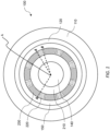
- FIG. 1 shows an example rotary machine 100 comprising a shaft 140, a rotor back iron 210, and a plurality of magnetic elements 220, 230.
- the expression "back iron” is a term of the art related to magnetic rotary machines, and does not imply that it comprises or consists of iron.
- the rotor back iron may comprise an axially-laminated stack of elements, for example comprising silicon steel (also known as electrical steel) or a cobalt-iron alloy.
- the shaft 140 is configured to rotate about a rotor axis A, and the rotor back iron 210 and the plurality of magnetic elements 220, 230 are each concentrically arranged with respect to the rotor axis A
- the rotor back 210 extends radially outwardly from the shaft 140, and the magnetic elements 220, 230 are supported on the rotor back iron 210 to extend radially outwardly from the rotor back iron 210.
- radial and angular as used herein with respect to such elements relates to the orientation direction magnetisation, with the radial elements being provided to have a radial orientation direction between poles, and the angular elements being provided to have an angular orientation direction between poles (which may be an orientation direction corresponding to a local angular direction or a tangent to a local angular direction at the respective element).
- a reference herein to a radial or angular element refers to those elements being provided to have such an orientation direction.
- the elements may be magnetised and demagnetised, and as such during application of the methods disclosed herein an element may be in a demagnetised state without a particular orientation direction, while still being referred to as an angular or radial element.
- Demagnetised elements may also retain their orientation direction when demagnetised.
- a Halbach array is a term of the art corresponding to a sequence of orientation directions for an array of adjacent magnetic elements, with advantages concerning augmentation of the magnetic field on one side of the array, and minimisation of the magnetic field on the opposing side of the array.
- a Halbach array may be defined by reference to the orientation directions of an alternating sequence of radial and angular magnetic elements.
- the Halbach array has a main side and an auxiliary side, with alternating radial elements having orientation directions towards the main side and auxiliary side respectively. The orientation directions of each angular element is always towards the adjacent radial element which has an orientation direction towards the main side.
- the rotary machine 100 shown in FIG. 1 further comprises a magnet retention sleeve 150 disposed radially outwardly of the magnetic elements 220, 230, and a stator lamination stack 110 disposed radially outwardly of the rotor and incorporating windings.
- a rotor is formed by the plurality of magnet elements 220, 230 mounted on the shaft 140, together with the rotor back iron 210 and the retention sleeve 150.
- a stator is formed by the stator lamination stack 110 and the windings, which is separated from the rotor by an air-gap 120.
- FIG. 1 illustrates an example rotary machine, and that the arrangements and methods disclosed herein are more generally applicable to a rotary machine or rotor comprising magnetic elements, preferably to magnetic elements arranged to form a Halbach array.
- the disclosure relates to methods and apparatus for selectively magnetising and demagnetising a subset of the magnetic elements 220, 230 that form an annular array of magnetic elements.
- the methods and apparatus disclosed below relate to controlling magnetic flux (e.g. controlling) for a magnetisation or demagnetisation effect in the subset of elements, while inhibiting the magnetisation or demagnetisation effect in the remaining elements (i.e. the remaining elements of the plurality, not belonging to the subset).
- the expression “primary” is to be used with respect to elements where a magnetisation or demagnetisation effect is to be directed, whereas the expression “secondary” is to be used with respect to an adjacent element where the respective effect is to be inhibited.
- FIG. 2 shows a partial cross-sectional view of an annular segment of the plurality of magnetic elements disposed on the rotor back iron 210, together with a magnetizer 310.
- the magnetizer 310 is disposed radially outside of the magnetic elements, at an angular location (with respect to an axis of the rotor) corresponding to a primary angular element 222.
- FIG. 2 also depicts the orientation directions corresponding to the magnetic elements, with radial arrows corresponding to radial elements and angular arrows (or arrows tangent to a local angular direction) corresponding to angular elements.
- the orientation directions correspond to a Halbach array.
- the radial elements adjacent to the primary angular element are referred to herein as primary radial elements 232, 234.
- the primary magnetic elements 222, 232, 234 (comprising the primary angular element and the or each primary radial element) is referred to herein as the primary set of magnetic elements.
- the magnetizer 310 causes a magnetic field 320 centred on the magnetizer 310, which corresponds to magnetic flux being induced in magnetic elements of the annular component.
- the resulting field lines of the magnetic field 320 correspond to the orientation directions of the primary set of magnetic elements 232, 222, 234.
- the field lines are clearly curved, they are generally aligned with the angular direction in the primary angular element, and generally aligned with the radial direction in the primary radial elements.
- the field lines may correspond to the respective orientation direction for a magnetic element when the angle between the orientation direction and the field line is less than an angle between the field line and an orthogonal orientation direction (where the orthogonal direction is a radial direction for an angular element, and is the angular direction for a radial element).
- FIG. 2 schematically shows how the field lines of the magnetic field do not correspond with the orientation directions for other magnetic elements adjacent to the primary set, in particular a secondary angular pole element 226 adjacent to the primary radial element 232.
- the field lines 320 are substantially perpendicular to the pole orientation. This may cause the respective magnetic element(s) to be incorrectly magnetised or demagnetised.
- the field lines do not correspond with the orientation direction of a secondary angular pole element 226, for other elements the field lines may be aligned but the magnetising effect may be opposite to the intended orientation direction. For example, it is apparent from FIG.
- FIG. 2 shows the magnetizer 310 disposed at a radial location relative to the magnetic elements so that the magnetizer is radially spaced apart from the primary angular pole element 222 by a radial distance referred to herein as a field separation. It may be that the field separation is relatively low to promote field line turning at the interface between the primary angular element and the primary radial element(s).
- the field lines may turn through a relatively low angle as they extend through the primary radial element(s) and the primary angular element; whereas the field lines may turn through a relatively higher angle when the field separation is relatively low, permitting the field lines to correspond to the radial orientation direction in the radial element(s), and to correspond to the angular orientation direction in the angular element(s). It may be that the field separation is not more than three times the radial thickness of the primary angular element 222, for example no more than twice the radial thickness of the primary angular element 222 or no more than the radial thickness of the primary angular element. In other examples arrangements, the field separation may be greater.
- the disclosure envisages placing a sleeve (e.g. a nonmagnetic sleeve) between the magnetizer and the respective magnetic element, and it may be that the radial thickness of the sleeve corresponds to or is less than the field separation.
- a sleeve e.g. a nonmagnetic sleeve
- each shield element 400, 410 has a rectilinear for example square, cross-section normal to the axis of the rotor.
- a shield element may have any suitable cross-sectional shape.
- each shield element 400, 410 is provided in the form of a busbar having an extent along the rotor axis A.
- the disclosure envisages a rotor comprising a plurality of annular rotor stacks, each rotor stack comprising an annular arrangement of magnetic elements as described herein.
- the annular arrangements of magnetic elements may be angularly offset over the stacks, for example such that there is an angular offset between corresponding angular elements having the same (angular) orientation direction.
- the shield element may be have a shape corresponding to the offset between stacks, for example with angularly-offset portions corresponding to respective rotor stacks.
- the shield element may have a stepped (e.g.
- the angular offset may be configured so that the angular position of the shield element along the rotor axis corresponds to an angular offset between corresponding elements of the rotor stacks, for example to correspond to the angular location of an angular element (e.g. a secondary angular element) as described above.
- the shield element(s) 400, 410 and magnetiser 310 may be provided on a common support structure, such as a support frame, which is configured to maintain the shield element(s) 400, 410 and magnetiser 310 at predetermined relative locations.
- the common support structure may be configured to maintain the shield element(s) 400, 410 and magnetiser 310 at a substantially equal radial location relative to a support axis of the support structure, and at an angular separation relative to the support axis which corresponds to the angular separation of the magnetiser 310 and shield element(s) for use in a magnetising or demagnetising operation as described herein (e.g. at angular locations corresponding to primary and secondary angular elements of a component as described herein).
- the common support structure may be configured to receive an annular component having a central axis (e.g.
- the shield element 400,410 is configured to inhibit magnetic flux from the magnetizer at the angular location corresponding to the shield element, including the magnetic element at that location, which is the secondary angular element 226 in the example of FIG. 3 .
- the shield element 400, 410 may further inhibit magnetic flex at angular locations beyond the shield element (e.g. on an opposite side of the shield element away from the magnetizer), for example the secondary radial element 236 as discussed above.
- a shield element may be configured to have that effect in a number of different ways relying on associated magnetic principles.
- the magnetic elements may comprise (e.g. consist of) permanent magnet material, for example rare earth permanent magnetic material such as Nedymium-lron-Boron alloys (Nd-Fe-B) or Samarium-Cobalt alloys (Sm-Co).
- permanent magnet material for example rare earth permanent magnetic material such as Nedymium-lron-Boron alloys (Nd-Fe-B) or Samarium-Cobalt alloys (Sm-Co).
- Example commercially available permanent magnets may be selected from the VACODYM (RTM) and VACOMAX (RTM) ranges available from VacuumSchmelze GmbH & Co. KG (VAC) of Hanau, Germany.
- a typical electrical resistivity for such Nd-Fe-B alloys may be in the range 1.2-1.6 ⁇ Ohm.m (electrical conductivity between 0.62-0.83 MS/m; and a typical electrical resistivity for such Sm-Co alloys may be 0.4-0.9 ⁇ Ohm/m (electrical conductivity of approximately 1.1 - 2.5 MS/m) (datasheet available at https://web.archive.org/web/20230118143719/https://vacuumschmelze.com/03 Docum ents/Brochures/VACODYM-VACOMAX%20en.pdf - see page 18).
- Other permanent magnet materials are known and may have electrical conductivities which are lower than the electrical conductivity of a selected shield material, for example less than 30MS/m, or between 0.1-30MS/m, for example between 0.1-10 MS/m, 0.1-5MS/m, or 0.5-5MS/m, or 0.5-2.5MS/m.
- NdFeB magnets available from Bunting Magnetics, UK may have an electrical conductivity of approximately 0.1 MS/m (datasheet available at /web/20230118142624/https://e-magnetsuk.com/introduction-to-neodymium-magnets/characteristics-of-ndfeb-magnets/ ) Copper has an electrical conductivity of 58 MS/m, and aluminium has an electrical conductivity of 35 MS/m.
- the shield element is not limited to comprising copper or aluminium, and may comprise any material or combination of materials which result in a shield element 400, 410 having a relatively higher electrical conductivity (or relatively lower electrical resistivity) than that of the or each magnetic element disposed about the periphery of the annular component 200.
- the shield element has a relatively higher thermal conductivity than the or each magnetic element.
- the thermal conductivity is related to the flux-inhibiting effect because a relatively high thermal conductivity permits heat generated by the induced eddy current to dissipate, and the electrical conductivity that provides the shielding effect may reduce if heat is not dissipated.
- the shield element 400 may cause the orientation of the field lines 320 passing through the primary radial elements 232, 234 to more closely correspond to the orientation direction of the primary radial elements 232, 234, in particular so that the local direction of the field lines is angularly offset from the local radial direction by a smaller amount, compared to the corresponding angle in the absence of the shield element(s).
- the shield element 400 may therefore concentrate/increase the magnetic flux in the primary set of magnetic elements 222, 232, 234, and may reduce the magnetic flux from the adjacent secondary angular pole elements 226.
- the magnetiser and shield element of the invention permits selective magnetisation and demagnetisation of magnet elements of a rotary machine.
- the option to selectively demagnetize (and magnetise) a rotary machine 100 facilitates easier inspection and safer disassembly of rotary machines 100.
- Selective demagnetisation and magnetisation permits selective disassembly (e.g. removal of a subset of the magnetic elements) without the hindrance of working against strong magnetic forces.
- the selective demagnetisation and magnetisation also reduces a requirement for specialist tooling required for handling and manipulating components (e.g. the magnetic elements) in the presence of strong magnetic forces. In contrast, more conventional or COTS (commercial off-the-shelf) tools may be used.
- the respective set of magnetic elements may be identified and demagnetized in isolation; rather than the user needing to demagnetize the entirety of the rotary machine to repair/inspect that one set of magnetic elements.
- the magnetising equipment may be configured and rate for lower electrical loads.
- a lower number of magnetisers may be required, for example only one magnetiser, as compared with an array of magnetisers for demagnetisation/magnetisation of an annular component.
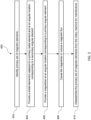
- FIG. 5 is a flowchart showing steps of a method for demagnetising a primary set of magnetic elements of an annular component of a rotary machine, and will be described with reference to the example of FIGs 3 and 4 .
- a primary set of magnetic elements to demagnetize is identified, for example comprising a primary angular element and one or two primary radial elements.
- a shield element is disposed at an angular location corresponding to a secondary angular pole element that is adjacent to a primary radial pole element.
- two shield elements are disposed at angular locations corresponding to secondary angular pole elements adjacent to the primary radial pole elements.
- the shield element(s) may be disposed radially outwardly or radially inwardly of the corresponding secondary angular pole element.
- a magnetizer is disposed at an angular location corresponding to a primary angular pole element.
- the magnetizer may further be disposed relative to the primary angular pole element so that the centre of the field lines of the magnetic field from the magnetizer is radially spaced apart from the primary angular pole element by a field separation.
- the field separation may not be more than twice the radial thickness of the primary angular pole element.
- the field separation may not be limited to twice the radial thickness of the primary angular pole element.
- Steps 404 and 406 can be conducted in any order.
- the magnetizer is caused to induce a magnetic flux in the rotor components of the annular component, thereby demagnetizing the primary set of magnetic elements in a demagnetising operation. Due to the presence of the shield element, the magnetizer induces a magnetic flux which is concentrated in the primary set of magnetic elements, whilst the magnetic flux in secondary angular pole elements is inhibited.
- the magnetic flux may be caused by providing a short duration pulse of electrical power through a magnetising coil of the magnetizer, which may be provided from a capacitor or capacitor bank, with a non-sinusoidal wave-form.
- step 410 following a demagnetisation operation, the user may disassemble and/or uninstall one or more of elements of the primary set from the rotary machine.
- the disassembled or removed element may subsequently be returned, or a replacement may be re-installed.
- the user may inspect and/or repair the primary set of magnetic elements.
- the user may carry out any process or procedure on the demagnetized primary set of magnetic elements, for example a maintenance procedure.
- the method 400 may be repeated to demagnetize one or more further sets of magnetic elements from the annular component of the rotary machine, each set being considered a respective "primary set" with respect to each further demagnetisation operation.
- FIG. 6 is a flowchart showing steps of a method for magnetising a primary set of magnetic elements of an annular component of a rotary machine.
- a set of demagnetized magnetic elements are installed onto the annular component of the rotary machine, for example corresponding to a primary set of magnetic elements as described herein. Otherwise, such magnetic elements may already be in place on the rotary machine.
- a primary set of magnetic elements to magnetize is identified, for example comprising a primary angular element and one or two primary radial elements as described herein.
- a magnetizer is disposed at an angular location corresponding to the primary angular element.
- the magnetizer may further be disposed relative to the primary angular pole element so that the centre of the field lines of the magnetic field from the magnetizer is radially spaced apart from the primary angular pole element by a field separation.
- the field separation may not be more than twice the radial thickness of the primary angular pole element.
- the field separation may not be limited to twice the radial thickness of the primary angular pole element.
- a shield element is disposed at an angular location corresponding to a secondary angular element that is adjacent to a primary radial pole element.
- two shield elements are disposed at angular locations corresponding to secondary angular pole elements adjacent to two primary radial pole elements.
- the shield element may be disposed radially outwardly or radially inwardly of the corresponding secondary angular element.
- Steps 506 and 508 may be conducted in any order.
- the magnetizer is caused to induce a magnetic flux in the rotor components of the annular component, thereby magnetizing the primary set of magnetic elements in a magnetisation operation.
- the polarity of the magnetic flux may be opposite to that of a magnetic flux that may be induced for demagnetisation. Due to the presence of the shield element, the magnetizer concentrates the magnetic flux in the primary set of magnetic elements, whilst the magnetic flux in secondary angular pole elements is inhibited.
- the method 500 may be repeated for further sets (primary sets) of magnetic elements of the annular component.
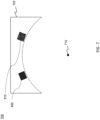
- FIG. 7 shows a flux assembly 700 for a flux arrangement, for example as described above with respect to FIG. 4 and FIG. 5 .
- the flux assembly 700 comprises a magnetiser 310 and a shield element 400 corresponding to those described above, mounted to a common support structure.
- FIG. 7 illustrates how the magnetiser 310 and shield element 400 are mutually arranged to be disposed relative to (e.g. around) an annular component, a location for which is indicated by the dashed line.
- the flux assembly has a support axis 710 along which it is configured to receive an annular component to be disposed radially within the magnetiser and the shield element.
- the support axis 710 is defined as a central axis of a cylindrical datum surface that intersects or opposes the magnetiser 310 and shield element 400, as shown by the dashed line in FIG. 7 .
- the magnetiser 310 and shield element 400 are disposed at positions which may correspond to angular locations of a primary angular element and a secondary angular element respectively. (e.g. by suitable positioning for a particular annular component).
- the flux assembly may comprise one or more further magnetiser(s) and one or more further shield elements.
- magnetising arrangements described elsewhere herein may comprise a flux assembly as described by way of example with respect to FIG. 7 .
- magnetising arrangements may comprise a common support structure which determines the relative position of the magnetiser(s) and shield element(s).
- the arrangements disclosed herein have advantages concerning flux leakage prevention, and in particular provide a means to prevent flux leakage with minimal equipment complexity and cost.
- the arrangements disclosed herein can achieve the magnetising and de-magnetising effects described herein with only one magnetizer (e.g. one magnetizer at an angular location, for example one magnetizer coil), avoiding additional equipment complexity, cost, and energy use associated with multi-coil or multi-magnetiser arrangements.
- Multi-coil arrangements may also require specific calibration and design of coils tailored to a shape and size of a magnetic element to mitigate flux leakage, whereas the arrangements disclosed herein mitigate flux leakage using a shield disposed at an appropriate angular location, and is considered to be more adaptable for magnetising and de-magnetising components of various shapes and sizes.
Landscapes
- Engineering & Computer Science (AREA)
- Power Engineering (AREA)
- Manufacturing & Machinery (AREA)
- Physics & Mathematics (AREA)
- Electromagnetism (AREA)
- Permanent Field Magnets Of Synchronous Machinery (AREA)
Abstract
A method of magnetising or demagnetising an annular component 200 for a rotary machine is disclosed, the annular component comprising an alternating arrangement of radial elements and angular elements for forming a Halbach array. A magnetizer 310 is caused to induce magnetic flux in a primary set of elements of the annular component comprising a primary radial element 232 and an adjacent primary angular element 222. A shield element 400 shields a secondary angular element 226 of the annular component from magnetic flux from the magnetizer. A flux arrangement for performing a magnetising or demagnetising method is also disclosed, and a flux assembly for such a flux arrangement.
Description
- The invention relates to methods of magnetising or demagnetising an annular component for a rotary machine, and a magnetising arrangement.
- It is known to magnetise and demagnetise elements of a permanent magnet component, such as a permanent magnet rotor for use in an electric machine. Known methods include pulse magnetisation and pulse demagnetisation, in which one or more magnetizers are controlled to cause magnetic flux in elements of the component to cause either magnetisation or demagnetisation of the respective elements. In the case of a permanent magnet rotor, it is known to conduct a magnetisation or demagnetisation operation for all elements of a permanent magnetic rotor at once, for example in a single pulse magnetisation or single pulse demagnetisation process.
- Simultaneous magnetisation or demagnetisation of a plurality (e.g. all) elements of a component may present practical difficulties, particularly with increasing component size. In particular, there may be practical limitations or difficulties associated with the design and configuration of an arrangement of magnetizers for such a magnetisation or demagnetisation operation, with complexity and cost of power electronics components scaling with size.
- The manufacture (e.g. assembly) and repair or maintenance of permanent magnetic rotors requires access to suitable magnetizers for magnetisation and/or demagnetisation operations. It is considered that many permanent magnet rotors may not be designed or commissioned on the basis of a requirement for future servicing and repair, which may require demagnetisation and subsequent magnetisation.
- According to a first aspect there is disclosed a method of magnetising or demagnetising an annular component for a rotary machine, the annular component comprising an alternating arrangement of radial elements and angular elements for forming a Halbach array in which the elements have respective radial and angular magnetic orientation directions, the method comprising:
- causing a magnetizer to induce magnetic flux in a primary set of elements of the annular component comprising a primary radial element and an adjacent primary angular element;
- wherein the magnetizer is disposed at an angular location corresponding to the primary angular element; and a shield element shielding a secondary angular element of the annular component from magnetic flux from the magnetizer;
- wherein the secondary angular element is adjacent to the primary radial element, and
- wherein the shield element is disposed at an angular location corresponding to the secondary angular element.
- It may be that the shield element is disposed radially outward of the secondary angular element.
- It may be that the primary set of elements of the annular component comprises the primary angular element and a plurality of primary radial elements.
- It may be that the primary set of elements of the annular component comprises the primary angular element disposed between two primary radial elements.
- It may be that the shield element comprises a shield material and each of the plurality of radial and angular elements of the component comprises a respective pole material. The electrical conductivity of the shield material may be greater than the electrical conductivity of the pole material of the primary radial element disposed between the primary angular element and the secondary angular element.
- It may be that the shield material has an electrical conductivity greater than the electrical conductivity of each of the plurality of radial and angular elements of the component, for example greater than the electrical conductivity of each respective pole material associated with the plurality of radial and angular elements.
- It may be that the shield element has an electrical conductivity of at least 9 MS/m, for example at least 25 MS/m or at least 30 MS/m. For example, the shield material may have an electrical conductivity of 9-63 MS/, for example between 20-63 MS/m, or 30-63 MS/m. By way of example, suitable materials for the shield material include silver 63 MS/m; copper (59.6 MS/m; aluminium 37.7 MS/m; iron 9.93 x10⁶ S/m.
- The or each pole material may have an electrical conductivity of less than the shield material, for example 0.01-30MS/m, 0.1-30MS/m, for example between 0.01-10 MS/m, 0.1-10 MS/m, 0.1-5MS/m, or 0.5-5MS/m, or 0.5-2.5MS/m.
- It may be that the shield element comprises a shield material and each of the plurality of radial and angular elements of the component comprises a respective pole material. It may be that the thermal conductivity of the shield material is greater than the thermal conductivity of the pole material of the primary radial element disposed between the primary angular element and the secondary angular element.
- It may be that the shield material has a thermal conductivity greater than the thermal conductivity of each of the plurality of radial and angular elements of the component, for example greater than the thermal conductivity of each respective pole material associated with the plurality of radial and angular elements.
- It may be that the shield element has a thermal conductivity of at least 50 W/m K, for example at least 90 W/m K or at least 200 W/m K. The thermal conductivity of the shield element may be 50-413 W/m K, for example in the range 90-413 W/m K. By way of example, suitable materials include silver (403 W/m K); copper (413 W/m K); (Aluminium 273W/m K); and iron 94 W/m K).
- The or each pole material may have a thermal conductivity of less than 50 W/m K, for example between 5-50 W/m K or between 5-15 W/m K (which is a typical range of thermal conductivity for Nd-Fe-B alloy or Sm-Co alloy pole material.
- The shield element may comprise (e.g. consist of) silver, copper, aluminium, or an alloy including any of these elements. The primary radial element between the primary and secondary angular elements may comprise (e.g. consist of) an Sm-Co alloy, an Nd-Fe-B alloy, an Al-Ni-Co alloy, or a ferrite magnetic material. The plurality of radial and angular elements of the component may comprise (e.g. consist of) an Sm-Co alloy, an Nd-Fe-B alloy, an Al-Ni-Co alloy, or a ferrite magnetic material
- It may be that there is an interface between the primary radial element and the secondary angular element, and wherein the shield element has a boundary at an angular location corresponding to the interface.
- It may be that the primary angular element has a radial thickness, and the magnetizer may be radially spaced apart from the primary angular element by a field separation. The field separation may be no more than twice the radial thickness of the primary angular element. The field separation may be no more than the radial thickness of the primary angular element. There may be a radial gap between the magnetizer and the annular component (e.g. an air gap).
- It may be that the magnetizer is caused to induce magnetic flux to demagnetize the primary set of elements in a demagnetisation operation; and the method may further comprise: conducting a maintenance operation for a maintenance element of the primary set of elements
- The maintenance operation may comprise: removing the maintenance element; and re-installing the maintenance element or installing a replacement maintenance element. The method may method further comprise: subsequently causing the magnetizer to induce a magnetic flux in the primary set of elements to magnetise the maintenance element in a magnetisation operation.
- It may be that at least some radial or angular elements of the annular component remain in place during the maintenance operation and the subsequent magnetisation of the maintenance element. It may be that each such remaining element is not subject to a demagnetisation operation and thereby remains magnetised throughout the demagnetisation operation, maintenance operation and magnetisation operation conducted for the maintenance element.
- The method may comprise a sequence of demagnetisation operations conducted for respective primary sets of elements of the annular component; and/or may comprise a sequence of magnetisation operations conducted for respective primary sets of elements of the annular component.
- The annular component may be a rotor for a rotary machine.
- According to a second aspect there is disclosed a magnetising arrangement comprising:
- an annular component for a rotary machine, the annular component comprising an alternating arrangement of radial elements and angular elements for forming a Halbach array in which the elements have respective radial and angular magnetic orientation directions;
- a flux assembly comprising:
- a magnetizer configured to induce a magnetic flux in the elements of the annular component; and
- a shield element;
- It may be that the flux assembly comprises a common support structure which supports the magnetizer and the shield element and is configured to receive the annular component radially within the magnetizer and the shield element so that the centroidal axis of the annular component is coincident with a support axis of the support structure.
- It may be that the magnetizer and the shield element are at a common radial position with respect to the support axis.
- According to a third aspect there is provided a flux assembly for a magnetising arrangement in accordance with the second aspect.
- The skilled person will appreciate that except where mutually exclusive, a feature described in relation to any one of the above aspects may be applied mutatis mutandis to any other aspect. Furthermore, except where mutually exclusive any feature described herein may be applied to any aspect and/or combined with any other feature described herein.
- Exemplary embodiments will now be described, by way of example only, with reference to the following drawings, in which:
-
FIG. 1 is a sectional front view of an example rotary machine showing radial and angular magnetic elements of a rotor arranged in a Halbach array; -
FIG. 2 is a sectional front view of the rotor (A-A) ofFIG. 1 provided with a magnetizer for inducing flux in magnetic elements of the rotor; -
FIG. 3 is a sectional front view of the rotor (A-B) ofFIG. 1 provided with a magnetizer and two shield elements; -
FIG. 4 is a sectional front view of the rotor (A-A) ofFIG. 1 provided with a magnetizer and shield element, with illustrated magnetic field lines; -
FIG. 5 is a flow chart of an example method for demagnetizing a primary set of magnetic elements of an example component; -
FIG. 6 is a flow chart of an example method for magnetizing a primary set of magnetic elements of an example component; and -
FIG. 7 is a sectional front view of an example flux assembly. -
FIG. 1 shows an examplerotary machine 100 comprising ashaft 140, a rotor backiron 210, and a plurality ofmagnetic elements shaft 140 is configured to rotate about a rotor axis A, and the rotor backiron 210 and the plurality ofmagnetic elements - As shown in
FIG. 1 , the rotor back 210 extends radially outwardly from theshaft 140, and themagnetic elements iron 210 to extend radially outwardly from the rotor backiron 210. - The plurality of
magnetic elements iron 210. The plurality ofmagnetic elements angular elements 220 andradial elements 230 in an alternating arrangement about the periphery of the rotor backiron 210. Each of the radial and angular elements is in the form of an angular segment of an annulus. The expressions "radial" and "angular" as used herein with respect to such elements relates to the orientation direction magnetisation, with the radial elements being provided to have a radial orientation direction between poles, and the angular elements being provided to have an angular orientation direction between poles (which may be an orientation direction corresponding to a local angular direction or a tangent to a local angular direction at the respective element). - A reference herein to a radial or angular element refers to those elements being provided to have such an orientation direction. As will become apparent from the further description below, the elements may be magnetised and demagnetised, and as such during application of the methods disclosed herein an element may be in a demagnetised state without a particular orientation direction, while still being referred to as an angular or radial element. Demagnetised elements may also retain their orientation direction when demagnetised.
- In the example of
Figure 1 , the radial and angular elements are provided to form a Halbach array. A Halbach array is a term of the art corresponding to a sequence of orientation directions for an array of adjacent magnetic elements, with advantages concerning augmentation of the magnetic field on one side of the array, and minimisation of the magnetic field on the opposing side of the array. For the purposes of the present disclosure in relation to an annular set of magnetic elements, a Halbach array may be defined by reference to the orientation directions of an alternating sequence of radial and angular magnetic elements. In particular, the Halbach array has a main side and an auxiliary side, with alternating radial elements having orientation directions towards the main side and auxiliary side respectively. The orientation directions of each angular element is always towards the adjacent radial element which has an orientation direction towards the main side. - The
rotary machine 100 shown inFIG. 1 further comprises amagnet retention sleeve 150 disposed radially outwardly of themagnetic elements stator lamination stack 110 disposed radially outwardly of the rotor and incorporating windings. In this example, a rotor is formed by the plurality ofmagnet elements shaft 140, together with the rotor backiron 210 and theretention sleeve 150. In this example, a stator is formed by thestator lamination stack 110 and the windings, which is separated from the rotor by an air-gap 120. - It will be appreciated that
FIG. 1 illustrates an example rotary machine, and that the arrangements and methods disclosed herein are more generally applicable to a rotary machine or rotor comprising magnetic elements, preferably to magnetic elements arranged to form a Halbach array. - The disclosure relates to methods and apparatus for selectively magnetising and demagnetising a subset of the
magnetic elements - As discussed above, while it is known to magnetise an entire annular set of magnetic elements simultaneously (e.g. by pulse magnetisation), there are also disadvantages to such an approach. These include the amount of energy required, and the complexity and expense of providing magnetisation equipment that circumscribes the full rotor. The methods and apparatus disclosed below permit a subset of the
magnetic elements - The methods and apparatus disclosed below relate to controlling magnetic flux (e.g. controlling) for a magnetisation or demagnetisation effect in the subset of elements, while inhibiting the magnetisation or demagnetisation effect in the remaining elements (i.e. the remaining elements of the plurality, not belonging to the subset).
- To aid the related further discussion, the expression "primary" is to be used with respect to elements where a magnetisation or demagnetisation effect is to be directed, whereas the expression "secondary" is to be used with respect to an adjacent element where the respective effect is to be inhibited.
-
FIG. 2 shows a partial cross-sectional view of an annular segment of the plurality of magnetic elements disposed on the rotor backiron 210, together with amagnetizer 310. - In the arrangement of
FIG. 2 , themagnetizer 310 is disposed radially outside of the magnetic elements, at an angular location (with respect to an axis of the rotor) corresponding to a primaryangular element 222. -
FIG. 2 also depicts the orientation directions corresponding to the magnetic elements, with radial arrows corresponding to radial elements and angular arrows (or arrows tangent to a local angular direction) corresponding to angular elements. In this example, the orientation directions correspond to a Halbach array. - The radial elements adjacent to the primary angular element are referred to herein as primary
radial elements magnetic elements - As shown in
FIG. 2 , themagnetizer 310 causes amagnetic field 320 centred on themagnetizer 310, which corresponds to magnetic flux being induced in magnetic elements of the annular component. - In this example arrangement, with the
magnetizer 310 disposed at the angular location corresponding to the primaryangular pole element 222, the resulting field lines of themagnetic field 320 correspond to the orientation directions of the primary set ofmagnetic elements -
FIG. 2 schematically shows how the field lines of the magnetic field do not correspond with the orientation directions for other magnetic elements adjacent to the primary set, in particular a secondaryangular pole element 226 adjacent to the primaryradial element 232. In contrast, thefield lines 320 are substantially perpendicular to the pole orientation. This may cause the respective magnetic element(s) to be incorrectly magnetised or demagnetised. Further, while the field lines do not correspond with the orientation direction of a secondaryangular pole element 226, for other elements the field lines may be aligned but the magnetising effect may be opposite to the intended orientation direction. For example, it is apparent fromFIG. 2 that further magnetic field lines beyond those shown would generally be aligned with the orientation direction for a secondaryradial element 236 adjacent to the secondaryangular element 226, but the magnetising effect may be opposite. Accordingly, when magnetised, theelement 236 may be partially demagnetised; and when de-magnetised, theelement 236 may be magnetised in the wrong direction. -
FIG. 2 shows themagnetizer 310 disposed at a radial location relative to the magnetic elements so that the magnetizer is radially spaced apart from the primaryangular pole element 222 by a radial distance referred to herein as a field separation. It may be that the field separation is relatively low to promote field line turning at the interface between the primary angular element and the primary radial element(s). In particular, if the field separation is relatively high, then the field lines may turn through a relatively low angle as they extend through the primary radial element(s) and the primary angular element; whereas the field lines may turn through a relatively higher angle when the field separation is relatively low, permitting the field lines to correspond to the radial orientation direction in the radial element(s), and to correspond to the angular orientation direction in the angular element(s). It may be that the field separation is not more than three times the radial thickness of the primaryangular element 222, for example no more than twice the radial thickness of the primaryangular element 222 or no more than the radial thickness of the primary angular element. In other examples arrangements, the field separation may be greater. The disclosure envisages placing a sleeve (e.g. a nonmagnetic sleeve) between the magnetizer and the respective magnetic element, and it may be that the radial thickness of the sleeve corresponds to or is less than the field separation. -
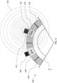
FIG. 3 shows amagnetising arrangement 300 which corresponds to the arrangement described above with respect toFIG. 2 , but in which ashield element 400 is provided and disposed at an angular location corresponding to a secondaryangular element 226 which is adjacent to the primaryradial element 232. In this example, there are primary radial elements on both anticlockwise and clockwise sides of the primaryangular element 222, and consequently there may be two corresponding secondary angular elements at respective clockwise and anticlockwise locations. Theshield element 400 inFIG. 3 is disposed at an anticlockwise location relative to the primaryangular element 222 and themagnetiser 310. There may optionally be afurther shield element 410 disposed at a corresponding clockwise secondary angular element, as in the example ofFIG. 3 . - In the example of
FIG. 3 , theshield elements angular pole elements 226. In other examples, the shield element(s) 400, 410 may be disposed radially inwardly of a secondaryangular pole element 226. A radially outward configuration for the shield element(s) may be more practical and convenient for a rotor, but for other annular components a radially-inward configuration may be more practical and convenient. - As shown in the example of
FIG. 3 , eachshield element - In the example of
FIG. 3 , eachshield element magnetiser 310 may be provided on a common support structure, such as a support frame, which is configured to maintain the shield element(s) 400, 410 andmagnetiser 310 at predetermined relative locations. The common support structure may be configured to maintain the shield element(s) 400, 410 andmagnetiser 310 at a substantially equal radial location relative to a support axis of the support structure, and at an angular separation relative to the support axis which corresponds to the angular separation of themagnetiser 310 and shield element(s) for use in a magnetising or demagnetising operation as described herein (e.g. at angular locations corresponding to primary and secondary angular elements of a component as described herein). The common support structure may be configured to receive an annular component having a central axis (e.g. a rotor axis as described herein) along the support axis, such that when the central axis and support axis are coincident the magnetiser and shield element(s) are positioned to perform the respective demagnetisation or magnetisation operations. The support structure may be configured to angularly rotate the magnetiser and shield element(s) together around the support axis for conducting such operations with respect to selected sets of magnetic elements. The support structure may be configured to permit repositioning of the magnetiser and shield elements at various angular locations corresponding for conducting such operations with respect to selected sets of magnetic elements. - In the arrangements shown in
FIG. 1 -FIG. 4 there is an angular gap (e.g. an air gap) formed between adjacent magnetic elements of theannular component 200. For example, there is an angular gap formed between the secondaryangular element 226, and the adjacent primaryradial element 232. Theshield element angular element 226 that is adjacent to the primaryradial pole element angular pole element 226 and the adjacent primaryradial pole element - The
shield element radial pole element 232, 234). - The
shield element radial pole element angular pole element 226. - In other arrangements, there may be no such angular gap formed between adjacent magnetic elements, as such, there may be a contact interface between a primary
radial pole element 232 and a secondaryangular pole element 226. In such examples, the shield element 400,410 may have a boundary at the angular location of the interface. - The shield element 400,410 is configured to inhibit magnetic flux from the magnetizer at the angular location corresponding to the shield element, including the magnetic element at that location, which is the secondary
angular element 226 in the example ofFIG. 3 . Theshield element radial element 236 as discussed above. A shield element may be configured to have that effect in a number of different ways relying on associated magnetic principles. - For example, a shield element may have a higher electrical conductivity (or lower electrical resistivity) than the or each corresponding magnetic element of the respective component (e.g. higher than the primary radial element(s) 232, 234. Without wishing to be bound by theory, it is considered that a shield element having a higher electrical conductivity (or lower electrical resistivity) than the respective magnetic element(s) can inhibit local magnetic flux owing to eddy currents. In particular, when disposed in the electric field corresponding to the magnetiser, eddy currents will form in a conductive shield element, and those eddy currents will generate their own magnetic flux that opposes the flux corresponding to the magnetizer, to provide a cancelling effect to significantly reduce (inhibit) the local flux at the angular location of the shield element. Accordingly, when visualised with the common concept of magnetic flux lines, the shield element may be considered to have the effect of inhibiting magnetic flux through at the angular location corresponding to the shield element, and concentrating magnetic flux in the angular location between the magnetiser and the shield element. The
shield element shield element annular component 200. - Similarly, it may be that the shield element has a relatively higher thermal conductivity than the or each magnetic element. The thermal conductivity is related to the flux-inhibiting effect because a relatively high thermal conductivity permits heat generated by the induced eddy current to dissipate, and the electrical conductivity that provides the shielding effect may reduce if heat is not dissipated.
-
FIG. 4 schematically shows the flux-inhibiting effect of theshield element 400, illustrated with respect to magnetic field lines associated with the magnetiser. As shown and in comparison withFIG. 2 , the shield element has the effect of re-directing thefield lines 320, such that the shield element may be considered to be configured to present an angular barrier that inhibits magnetic flux, and may therefore inhibit (e.g. substantially reduce) magnetic flux in the secondaryangular element 226. As such, themagnetizer 310 andshield element 400 are together configured to concentrate an induced magnetic flux in the primary set of magnetic elements of the annular component. - By re-directing the field lines 320 (e.g. as compared with those of
FIG. 2 ), theshield element 400 may cause the orientation of thefield lines 320 passing through the primaryradial elements radial elements shield element 400 may therefore concentrate/increase the magnetic flux in the primary set ofmagnetic elements angular pole elements 226. - By concentrating and/or improving an orientation of magnetic flux in magnetic elements for a magnetising or demagnetising effect, the magnetiser and shield element of the invention permits selective magnetisation and demagnetisation of magnet elements of a rotary machine.
- The option to selectively demagnetize (and magnetise) a
rotary machine 100, for example by demagnetising one set of magnetic elements at a time, facilitates easier inspection and safer disassembly ofrotary machines 100. Selective demagnetisation and magnetisation permits selective disassembly (e.g. removal of a subset of the magnetic elements) without the hindrance of working against strong magnetic forces. The selective demagnetisation and magnetisation also reduces a requirement for specialist tooling required for handling and manipulating components (e.g. the magnetic elements) in the presence of strong magnetic forces. In contrast, more conventional or COTS (commercial off-the-shelf) tools may be used. - Furthermore, in the event that a limited repair or inspection is required, for example on one or a subset of magnetic elements of the component, the respective set of magnetic elements may be identified and demagnetized in isolation; rather than the user needing to demagnetize the entirety of the rotary machine to repair/inspect that one set of magnetic elements.
- In addition to advantages associated with component handling, removal and repair, there are also advantages associated with the provision of the magnetising equipment. In particular, the power and current draw for selectively demagnetising/magnetising a subset of the magnetic elements of a component is commensurately lower than the power and current draw for demagnetising/magnetising a full annular component. Accordingly, the magnetising equipment may be configured and rate for lower electrical loads. Yet further, a lower number of magnetisers may be required, for example only one magnetiser, as compared with an array of magnetisers for demagnetisation/magnetisation of an annular component.
- Similar principles and advantages apply with respect to magnetisation (e.g. re-magnetisation).
- Although an example has been described in which there are two shield elements associated with one magnetiser, in other arrangements there may be only one shield element disposed at an angular location corresponding to a secondary angular pole element that is adjacent to a primary radial pole element.
-
FIG. 5 is a flowchart showing steps of a method for demagnetising a primary set of magnetic elements of an annular component of a rotary machine, and will be described with reference to the example ofFIGs 3 and4 . - In
step 402, a primary set of magnetic elements to demagnetize is identified, for example comprising a primary angular element and one or two primary radial elements. Instep 404, a shield element is disposed at an angular location corresponding to a secondary angular pole element that is adjacent to a primary radial pole element. Preferably, and as shown inFIG. 3 , instep 404, two shield elements are disposed at angular locations corresponding to secondary angular pole elements adjacent to the primary radial pole elements. - The shield element(s) may be disposed radially outwardly or radially inwardly of the corresponding secondary angular pole element.
- In
step 406, a magnetizer is disposed at an angular location corresponding to a primary angular pole element. Instep 406, the magnetizer may further be disposed relative to the primary angular pole element so that the centre of the field lines of the magnetic field from the magnetizer is radially spaced apart from the primary angular pole element by a field separation. The field separation may not be more than twice the radial thickness of the primary angular pole element. - For example, the field separation may not be limited to twice the radial thickness of the primary angular pole element.
Steps step 408, the magnetizer is caused to induce a magnetic flux in the rotor components of the annular component, thereby demagnetizing the primary set of magnetic elements in a demagnetising operation. Due to the presence of the shield element, the magnetizer induces a magnetic flux which is concentrated in the primary set of magnetic elements, whilst the magnetic flux in secondary angular pole elements is inhibited. For example, the magnetic flux may be caused by providing a short duration pulse of electrical power through a magnetising coil of the magnetizer, which may be provided from a capacitor or capacitor bank, with a non-sinusoidal wave-form. Instep 410, following a demagnetisation operation, the user may disassemble and/or uninstall one or more of elements of the primary set from the rotary machine. The disassembled or removed element may subsequently be returned, or a replacement may be re-installed. Additionally or alternatively, instep 410, the user may inspect and/or repair the primary set of magnetic elements. Additionally or alternatively, instep 410, the user may carry out any process or procedure on the demagnetized primary set of magnetic elements, for example a maintenance procedure. - The
method 400 may be repeated to demagnetize one or more further sets of magnetic elements from the annular component of the rotary machine, each set being considered a respective "primary set" with respect to each further demagnetisation operation. -
FIG. 6 is a flowchart showing steps of a method for magnetising a primary set of magnetic elements of an annular component of a rotary machine. - Optionally in
step 502, a set of demagnetized magnetic elements are installed onto the annular component of the rotary machine, for example corresponding to a primary set of magnetic elements as described herein. Otherwise, such magnetic elements may already be in place on the rotary machine. Instep 504, a primary set of magnetic elements to magnetize is identified, for example comprising a primary angular element and one or two primary radial elements as described herein. - In
step 506, a magnetizer is disposed at an angular location corresponding to the primary angular element. Instep 506, the magnetizer may further be disposed relative to the primary angular pole element so that the centre of the field lines of the magnetic field from the magnetizer is radially spaced apart from the primary angular pole element by a field separation. The field separation may not be more than twice the radial thickness of the primary angular pole element. For example, the field separation may not be limited to twice the radial thickness of the primary angular pole element. - In
step 508, a shield element is disposed at an angular location corresponding to a secondary angular element that is adjacent to a primary radial pole element. Preferably, and as shown inFIG. 3 , instep 508, two shield elements are disposed at angular locations corresponding to secondary angular pole elements adjacent to two primary radial pole elements. - The shield element may be disposed radially outwardly or radially inwardly of the corresponding secondary angular element.
-
Steps - In
step 510, the magnetizer is caused to induce a magnetic flux in the rotor components of the annular component, thereby magnetizing the primary set of magnetic elements in a magnetisation operation. The polarity of the magnetic flux may be opposite to that of a magnetic flux that may be induced for demagnetisation. Due to the presence of the shield element, the magnetizer concentrates the magnetic flux in the primary set of magnetic elements, whilst the magnetic flux in secondary angular pole elements is inhibited. - The
method 500 may be repeated for further sets (primary sets) of magnetic elements of the annular component. -
FIG. 7 shows aflux assembly 700 for a flux arrangement, for example as described above with respect toFIG. 4 andFIG. 5 . Theflux assembly 700 comprises amagnetiser 310 and ashield element 400 corresponding to those described above, mounted to a common support structure.FIG. 7 illustrates how themagnetiser 310 andshield element 400 are mutually arranged to be disposed relative to (e.g. around) an annular component, a location for which is indicated by the dashed line. The flux assembly has asupport axis 710 along which it is configured to receive an annular component to be disposed radially within the magnetiser and the shield element. In this example, thesupport axis 710 is defined as a central axis of a cylindrical datum surface that intersects or opposes themagnetiser 310 andshield element 400, as shown by the dashed line inFIG. 7 . - The
magnetiser 310 andshield element 400 are disposed at positions which may correspond to angular locations of a primary angular element and a secondary angular element respectively. (e.g. by suitable positioning for a particular annular component). As disclosed elsewhere herein, the flux assembly may comprise one or more further magnetiser(s) and one or more further shield elements. - The magnetising arrangements described elsewhere herein (i.e. including an annular component, magnetiser(s) and shield element(s)) may comprise a flux assembly as described by way of example with respect to
FIG. 7 . In particular, such magnetising arrangements may comprise a common support structure which determines the relative position of the magnetiser(s) and shield element(s). - The arrangements disclosed herein have advantages concerning flux leakage prevention, and in particular provide a means to prevent flux leakage with minimal equipment complexity and cost. The arrangements disclosed herein can achieve the magnetising and de-magnetising effects described herein with only one magnetizer (e.g. one magnetizer at an angular location, for example one magnetizer coil), avoiding additional equipment complexity, cost, and energy use associated with multi-coil or multi-magnetiser arrangements. Multi-coil arrangements may also require specific calibration and design of coils tailored to a shape and size of a magnetic element to mitigate flux leakage, whereas the arrangements disclosed herein mitigate flux leakage using a shield disposed at an appropriate angular location, and is considered to be more adaptable for magnetising and de-magnetising components of various shapes and sizes.
- The inventors have also found that providing the shield element significantly reduces mechanical stress in a coil of the magnetiser during a magnetising or de-magnetising operation.
- As mentioned elsewhere herein, the use of the shield element localises a magnetising or de-magnetising effect, permitting a sequential or partial magnetising or de-magnetising operation applied to a subset of magnetic elements of a larger component, thereby reducing a peak energy requirement for the magnetising or de-magnetising operation compared to arrangements which act on all elements of a component.
wherein the shield element is configured to present a barrier to inhibit magnetic flux in the annular component at an angular location corresponding to the shield element; wherein the flux assembly is configured to be disposed relative to the annular component so that, with the magnetizer at an angular location corresponding to a primary angular element and the shield element at an angular location corresponding to a secondary angular element, the magnetizer is configured to induce magnetic flux in a primary set of elements comprising the primary radial element and an adjacent primary angular element, with the shield element shielding the secondary angular element from the magnetic flux.
Claims (15)
- A method of magnetising or demagnetising an annular component for a rotary machine, the annular component comprising an alternating arrangement of radial elements and angular elements for forming a Halbach array in which the elements have respective radial and angular magnetic orientation directions, the method comprising:causing a magnetizer to induce magnetic flux in a primary set of elements of the annular component comprising a primary radial element and an adjacent primary angular element;
wherein the magnetizer is disposed at an angular location corresponding to the primary angular element; and a shield element shielding a secondary angular element of the annular component from magnetic flux from the magnetizer;wherein the secondary angular element is adjacent to the primary radial element, and wherein the shield element is disposed at an angular location corresponding to the secondary angular element. - The method claim 1, wherein the shield element is disposed radially outward of the secondary angular element.
- The method of claim 1 or 2, wherein the primary set of elements of the annular component comprises the primary angular element and a plurality of primary radial elements.
- The method of any preceding claim, wherein the shield element comprises a shield material and each of the plurality of radial and angular elements of the component comprises a respective pole material;
wherein the electrical conductivity of the shield material is greater than the electrical conductivity of the pole material of the primary radial element disposed between the primary angular element and the secondary angular element. - The method of any preceding claim, wherein the shield element has an electrical conductivity of at least 9 MS/m, for example at least 25 MS/m or at least 30 MS/m.
- The method of any preceding claim, wherein the shield element comprises a shield material and each of the plurality of radial and angular elements of the component comprises a respective pole material;
wherein the thermal conductivity of the shield material is greater than the thermal conductivity of the pole material of the primary radial element disposed between the primary angular element and the secondary angular element. - The method of any preceding claim, wherein the shield element has a thermal conductivity of at least 50 W/m K, for example at least 90 W/m K or at least 200 W/m K.
- The method of any preceding claim 1, wherein there is an interface between the primary radial element and the secondary angular element, and wherein the shield element has a boundary at an angular location corresponding to the interface.
- The method of any preceding claim, where the primary angular element has a radial thickness; andwherein the magnetizer is radially spaced apart from the primary angular element by a field separation; andwherein the field separation is no more than twice the radial thickness of the primary angular element.
- The method of any preceding claim, wherein the magnetizer is caused to induce magnetic flux to demagnetize the primary set of elements in a demagnetisation operation; the method further comprising:
conducting a maintenance operation for a maintenance element of the primary set of elements. - The method of claim 10, wherein the maintenance operation comprises:removing the maintenance element; andre-installing the maintenance element or installing a replacement maintenance element; and
wherein the method further comprises:subsequently causing the magnetizer to induce a magnetic flux in the primary set of elements to magnetise the maintenance element in a magnetisation operation. - The method of claim 11, wherein at least some radial or angular elements of the annular component remain in place without during the maintenance operation and the subsequent magnetisation of the maintenance element.
- A magnetising arrangement comprising:an annular component for a rotary machine, the annular component comprising an alternating arrangement of radial elements and angular elements for forming a Halbach array in which the elements have respective radial and angular magnetic orientation directions;a flux assembly comprising:a magnetizer configured to induce a magnetic flux in the elements of the annular component; anda shield element;wherein the magnetizer and shield element are angularly spaced apart with respect to a centroidal axis of the annular component;wherein the shield element is configured to present a barrier to inhibit magnetic flux in the annular component at an angular location corresponding to the shield element;wherein the flux assembly is configured to be disposed relative to the annular component so that, with the magnetizer at an angular location corresponding to a primary angular element and the shield element at an angular location corresponding to a secondary angular element, the magnetizer is configured to induce magnetic flux in a primary set of elements comprising the primary radial element and an adjacent primary angular element, with the shield element shielding the secondary angular element from the magnetic flux.
- A magnetising arrangement according to claim 13, wherein the flux assembly comprises a common support structure which supports the magnetizer and the shield element, and is configured to receive the annular component radially within the magnetizer and the shield element so that the centroidal axis of the annular component is coincident with a support axis of the support structure.
- A magnetising arrangement according to claim 14, wherein the magnetizer and the shield element are at a common radial position with respect to the support axis.
Applications Claiming Priority (1)
| Application Number | Priority Date | Filing Date | Title |
|---|---|---|---|
| GBGB2305114.7A GB202305114D0 (en) | 2023-04-06 | 2023-04-06 | Magnetisation and demagnetisation of a component |
Publications (1)
| Publication Number | Publication Date |
|---|---|
| EP4451297A1 true EP4451297A1 (en) | 2024-10-23 |
Family
ID=86378860
Family Applications (1)
| Application Number | Title | Priority Date | Filing Date |
|---|---|---|---|
| EP24162000.4A Withdrawn EP4451297A1 (en) | 2023-04-06 | 2024-03-07 | Magnetisation and demagnetisation of a component |
Country Status (3)
| Country | Link |
|---|---|
| US (1) | US12609566B2 (en) |
| EP (1) | EP4451297A1 (en) |
| GB (1) | GB202305114D0 (en) |
Families Citing this family (1)
| Publication number | Priority date | Publication date | Assignee | Title |
|---|---|---|---|---|
| CN119420062A (en) * | 2024-11-05 | 2025-02-11 | 河南科技大学 | 12:4 slot-pole ratio inter-pole bearingless brushless DC motor and manufacturing method |
Citations (4)
| Publication number | Priority date | Publication date | Assignee | Title |
|---|---|---|---|---|
| US20060220484A1 (en) * | 2005-03-31 | 2006-10-05 | Stephens Charles M | System and method for magnetization of permanent magnet rotors in electrical machines |
| US20090009012A1 (en) * | 2007-07-03 | 2009-01-08 | General Electric Company | Assembly and method for magnetization of permanent magnet rotors in electrical machines |
| WO2014187792A1 (en) * | 2013-05-23 | 2014-11-27 | Asml Netherlands B.V. | Lithographic apparatus and device manufacturing method |
| CN115188557A (en) * | 2022-05-23 | 2022-10-14 | 宁波科星材料科技有限公司 | Magnetizing device and magnetizing method |
Family Cites Families (2)
| Publication number | Priority date | Publication date | Assignee | Title |
|---|---|---|---|---|
| US8141234B2 (en) * | 2009-10-19 | 2012-03-27 | General Electric Company | Optimal magnetization of non-magnetized permanent magnet segments in electrical machines |
| CN113903542B (en) | 2021-09-02 | 2022-05-20 | 华中科技大学 | Magnetizing method and device for linear Halbach array |
-
2023
- 2023-04-06 GB GBGB2305114.7A patent/GB202305114D0/en not_active Ceased
-
2024
- 2024-03-07 EP EP24162000.4A patent/EP4451297A1/en not_active Withdrawn
- 2024-03-12 US US18/602,254 patent/US12609566B2/en active Active
Patent Citations (4)
| Publication number | Priority date | Publication date | Assignee | Title |
|---|---|---|---|---|
| US20060220484A1 (en) * | 2005-03-31 | 2006-10-05 | Stephens Charles M | System and method for magnetization of permanent magnet rotors in electrical machines |
| US20090009012A1 (en) * | 2007-07-03 | 2009-01-08 | General Electric Company | Assembly and method for magnetization of permanent magnet rotors in electrical machines |
| WO2014187792A1 (en) * | 2013-05-23 | 2014-11-27 | Asml Netherlands B.V. | Lithographic apparatus and device manufacturing method |
| CN115188557A (en) * | 2022-05-23 | 2022-10-14 | 宁波科星材料科技有限公司 | Magnetizing device and magnetizing method |
Also Published As
| Publication number | Publication date |
|---|---|
| US20240339897A1 (en) | 2024-10-10 |
| US12609566B2 (en) | 2026-04-21 |
| GB202305114D0 (en) | 2023-05-24 |
Similar Documents
| Publication | Publication Date | Title |
|---|---|---|
| US3296471A (en) | Dynamoelectric machine | |
| Rahman et al. | Performance of large line-start permanent magnet synchronous motors | |
| US8258906B2 (en) | Superconducting magnetizer | |
| US12609566B2 (en) | Magnetisation and demagnetisation of a component | |
| US3678436A (en) | Magnetizing apparatus and method | |
| EP2020662A2 (en) | Assembly and method for magnetization of permanent magnet rotors in electrical machines | |
| EP1739808A2 (en) | System and method for protecting magnetic elements of an electrical machine from demagnetization | |
| US8151439B2 (en) | Method for mounting a magnetic pole and associated rotor | |
| KR101263350B1 (en) | axial flux permanent magnet generator | |
| EP3249792A1 (en) | Rotor assembly for a power generation system | |
| JPS5886835A (en) | rotating electric machine | |
| US9620275B2 (en) | Method of constructing a rotor for a line start interior permanent magnet motor | |
| US20200059140A1 (en) | Production method and disassembly method for a rotary permanently excited electrical machine | |
| EP2919369A1 (en) | Electromagnetic generator | |
| JP2002238194A (en) | Rotor structure of permanent magnet motor | |
| US7291958B2 (en) | Rotating back iron for synchronous motors/generators | |
| US20170025906A1 (en) | Core for electrical machine | |
| US8344843B2 (en) | Flux transfer device | |
| JP7117978B2 (en) | Annealing method for rotary electric machine stator core | |
| JP2021068594A (en) | Induction heating device and induction heating method for rotating electric machine stator core | |
| JP2013121186A (en) | Permanent magnet rotary electric machine | |
| CN101986530A (en) | High-power density motor with multidirectional magnetic field | |
| Zhu et al. | Structural Design for Post-Assembly Magnetization of Low-Speed High-Torque PMSM in Consideration of Eddy Current Effect | |
| JP6525206B2 (en) | Rotor and rotating electric machine | |
| JP7334103B2 (en) | Induction heating device and induction heating method for rotary electric machine stator core |
Legal Events
| Date | Code | Title | Description |
|---|---|---|---|
| PUAI | Public reference made under article 153(3) epc to a published international application that has entered the european phase |
Free format text: ORIGINAL CODE: 0009012 |
|
| STAA | Information on the status of an ep patent application or granted ep patent |
Free format text: STATUS: THE APPLICATION HAS BEEN PUBLISHED |
|
| AK | Designated contracting states |
Kind code of ref document: A1 Designated state(s): AL AT BE BG CH CY CZ DE DK EE ES FI FR GB GR HR HU IE IS IT LI LT LU LV MC ME MK MT NL NO PL PT RO RS SE SI SK SM TR |
|
| STAA | Information on the status of an ep patent application or granted ep patent |
Free format text: STATUS: THE APPLICATION IS DEEMED TO BE WITHDRAWN |
|
| 18D | Application deemed to be withdrawn |
Effective date: 20250424 |