EP4451187A1 - Occupation rate determining module, system and method of determining an occupancy of a cargo repository - Google Patents
Occupation rate determining module, system and method of determining an occupancy of a cargo repository Download PDFInfo
- Publication number
- EP4451187A1 EP4451187A1 EP23168694.0A EP23168694A EP4451187A1 EP 4451187 A1 EP4451187 A1 EP 4451187A1 EP 23168694 A EP23168694 A EP 23168694A EP 4451187 A1 EP4451187 A1 EP 4451187A1
- Authority
- EP
- European Patent Office
- Prior art keywords
- cargo
- repository
- occupation rate
- camera
- determining module
- Prior art date
- Legal status (The legal status is an assumption and is not a legal conclusion. Google has not performed a legal analysis and makes no representation as to the accuracy of the status listed.)
- Withdrawn
Links
Images







Classifications
-
- G—PHYSICS
- G06—COMPUTING OR CALCULATING; COUNTING
- G06Q—INFORMATION AND COMMUNICATION TECHNOLOGY [ICT] SPECIALLY ADAPTED FOR ADMINISTRATIVE, COMMERCIAL, FINANCIAL, MANAGERIAL OR SUPERVISORY PURPOSES; SYSTEMS OR METHODS SPECIALLY ADAPTED FOR ADMINISTRATIVE, COMMERCIAL, FINANCIAL, MANAGERIAL OR SUPERVISORY PURPOSES, NOT OTHERWISE PROVIDED FOR
- G06Q10/00—Administration; Management
- G06Q10/08—Logistics, e.g. warehousing, loading or distribution; Inventory or stock management
-
- B—PERFORMING OPERATIONS; TRANSPORTING
- B60—VEHICLES IN GENERAL
- B60R—VEHICLES, VEHICLE FITTINGS, OR VEHICLE PARTS, NOT OTHERWISE PROVIDED FOR
- B60R1/00—Optical viewing arrangements; Real-time viewing arrangements for drivers or passengers using optical image capturing systems, e.g. cameras or video systems specially adapted for use in or on vehicles
- B60R1/20—Real-time viewing arrangements for drivers or passengers using optical image capturing systems, e.g. cameras or video systems specially adapted for use in or on vehicles
- B60R1/29—Real-time viewing arrangements for drivers or passengers using optical image capturing systems, e.g. cameras or video systems specially adapted for use in or on vehicles for viewing an area inside the vehicle, e.g. for viewing passengers or cargo
-
- B—PERFORMING OPERATIONS; TRANSPORTING
- B60—VEHICLES IN GENERAL
- B60R—VEHICLES, VEHICLE FITTINGS, OR VEHICLE PARTS, NOT OTHERWISE PROVIDED FOR
- B60R11/00—Arrangements for holding or mounting articles, not otherwise provided for
- B60R11/04—Mounting of cameras operative during drive; Arrangement of controls thereof relative to the vehicle
-
- G—PHYSICS
- G01—MEASURING; TESTING
- G01S—RADIO DIRECTION-FINDING; RADIO NAVIGATION; DETERMINING DISTANCE OR VELOCITY BY USE OF RADIO WAVES; LOCATING OR PRESENCE-DETECTING BY USE OF THE REFLECTION OR RERADIATION OF RADIO WAVES; ANALOGOUS ARRANGEMENTS USING OTHER WAVES
- G01S15/00—Systems using the reflection or reradiation of acoustic waves, e.g. sonar systems
- G01S15/02—Systems using the reflection or reradiation of acoustic waves, e.g. sonar systems using reflection of acoustic waves
- G01S15/06—Systems determining the position data of a target
- G01S15/08—Systems for measuring distance only
-
- G—PHYSICS
- G01—MEASURING; TESTING
- G01S—RADIO DIRECTION-FINDING; RADIO NAVIGATION; DETERMINING DISTANCE OR VELOCITY BY USE OF RADIO WAVES; LOCATING OR PRESENCE-DETECTING BY USE OF THE REFLECTION OR RERADIATION OF RADIO WAVES; ANALOGOUS ARRANGEMENTS USING OTHER WAVES
- G01S15/00—Systems using the reflection or reradiation of acoustic waves, e.g. sonar systems
- G01S15/88—Sonar systems specially adapted for specific applications
-
- G—PHYSICS
- G01—MEASURING; TESTING
- G01S—RADIO DIRECTION-FINDING; RADIO NAVIGATION; DETERMINING DISTANCE OR VELOCITY BY USE OF RADIO WAVES; LOCATING OR PRESENCE-DETECTING BY USE OF THE REFLECTION OR RERADIATION OF RADIO WAVES; ANALOGOUS ARRANGEMENTS USING OTHER WAVES
- G01S17/00—Systems using the reflection or reradiation of electromagnetic waves other than radio waves, e.g. lidar systems
- G01S17/02—Systems using the reflection of electromagnetic waves other than radio waves
- G01S17/06—Systems determining position data of a target
- G01S17/08—Systems determining position data of a target for measuring distance only
-
- G—PHYSICS
- G06—COMPUTING OR CALCULATING; COUNTING
- G06V—IMAGE OR VIDEO RECOGNITION OR UNDERSTANDING
- G06V20/00—Scenes; Scene-specific elements
- G06V20/50—Context or environment of the image
- G06V20/52—Surveillance or monitoring of activities, e.g. for recognising suspicious objects
-
- B—PERFORMING OPERATIONS; TRANSPORTING
- B60—VEHICLES IN GENERAL
- B60R—VEHICLES, VEHICLE FITTINGS, OR VEHICLE PARTS, NOT OTHERWISE PROVIDED FOR
- B60R11/00—Arrangements for holding or mounting articles, not otherwise provided for
- B60R2011/0001—Arrangements for holding or mounting articles, not otherwise provided for characterised by position
- B60R2011/0003—Arrangements for holding or mounting articles, not otherwise provided for characterised by position inside the vehicle
- B60R2011/0036—Luggage compartment
-
- H—ELECTRICITY
- H04—ELECTRIC COMMUNICATION TECHNIQUE
- H04N—PICTORIAL COMMUNICATION, e.g. TELEVISION
- H04N23/00—Cameras or camera modules comprising electronic image sensors; Control thereof
- H04N23/57—Mechanical or electrical details of cameras or camera modules specially adapted for being embedded in other devices
Definitions
- Embodiments according to the invention related to an occupation rate determining module and a method of determining an occupancy of a cargo repository.
- US2007/0040677 describes a device that detects the presence of cargo within a container using microwave radio frequency (RF) energy.
- RF microwave radio frequency
- the cargo sensor is placed within the inside wall of the cargo trailer such that portions of its housing extend within a space created between the inside wall and outside wall. This makes it difficult to install the sensor within the container as an add-on device, since the truck inside has to be modified.
- the inventors of the present application realized that one problem encountered when trying to install a device for monitoring an occupancy of a cargo repository stems from the fact that sometimes a power supply is not available in the cargo repository, that sometimes the cargo repository itself has to be modified and that the device may be hit by cargo loaded onto or unloaded from the cargo repository.
- This difficulty is overcome by limiting a determination of the occupation rate of the cargo repository to times at which a state of a door of the cargo repository changes so that a power consumption of the device is reduced.
- the senor for detecting a state of the door, the camera for taking an image of the loading area and the processor for determining the occupation rate of the cargo repository are accommodated in a common housing. This allows an easy installation of the device within the cargo repository, since the sensor, the camera and the processor do not have to be installed separately. Even further, the housing provides a protection of the sensor, the camera and the processor from being hit by cargo.
- An embodiment relates to an occupation rate determining module configured to determine an occupancy of a cargo repository equipped with a door.
- the occupation rate determining module comprises a sensor configured to detect a state of the door of the cargo repository, a camera having a field of view including all corners of a loading area of the cargo repository and a processor configured to determine, based on an image taken by the camera, the occupation rate of the cargo repository when the sensor detects a change of the state of the door from an open state to a closed state and/or from a closed state to an open state.
- the occupation rate determining module comprises a housing accommodating the sensor, the camera and the processor.
- a further embodiment relates to a system comprising a cargo repository and the occupation rate determining module.
- the housing of the occupation rate determining module is mounted to the cargo repository to direct the sensor to the door of the cargo repository and to direct the camera to the loading area of the cargo repository with the field of view including all corners of the loading area of the cargo repository.
- a position or relative arrangement of the camera and the sensor within the housing may be fixed and only the mounting of the housing to the cargo repository may be flexible. This reduces a complexity at a mounting of the occupation rate determining module, since it is not necessary to mount the sensor, the camera and the processor individually and check whether same are directed to the correct areas within the cargo repository.
- An even further embodiment is directed to a method of determining an occupancy of a cargo repository equipped with a door using the occupation rate determining module.
- the method comprises taking an image of a loading area of the cargo repository using a camera having a field of view including all corners of the loading area; detecting a change of the state of the door of the cargo repository from an open state to a closed state and/or from a closed state to an open state; upon detecting the change of the state of the door, determining, based on the image taken by the camera, the occupation rate of the cargo repository; and not determining the occupation rate of the cargo repository unless a change of the state of the door is detected.
- Fig. 1 shows an occupation rate determining module 10 configured to determine an occupancy of a cargo repository 20 equipped with a door 22.
- the cargo repository 20 may be a trailer, a truck hold, a cargo container or a storage room.
- the door 22 may be a conventional door or a flap or hatch configured to be opened and/or closed.
- the occupation rate determining module 10 comprises a sensor 12, a camera 14 and a processor 16.
- the sensor 12, the camera 14 and the processor 16 are arranged within a housing 18.
- the housing 18 may define a relative position between the sensor 12 and the camera 14. Therefore it is not necessary to arrange the individual units of the occupation rate determining module 10 individually. Instead, with the arrangement of the housing 18 within the cargo repository 20 a field of view 13 of the sensor 12 and a field of view 15 of the camera 14, i.e. a camera scope range, can be defined. Thus it is easy to install the occupation rate determining module 10 within the cargo repository 20, since only one module is to be arranged or mounted.
- a mounting surface 17 of the housing 18, which is fixable or mountable to a surface of the cargo repository 20, is inclined, e.g., has a predetermined gradient, slope or tilt, so that the loading area is covered by the camera 14, the position of which, e.g., is fixed within the housing 18, and so that the door 22 is monitored by the sensor 12, the position of which, e.g., is fixed within the housing 18.
- a structure of the module 10, e.g., the housing 18, may have already the necessary tilt to cover the loadin area of the cargo repository 20 without an additional hinge 34 as shown in Fig. 2a to 3b .
- the mounting surface 17 may be mounted to the surface of the cargo repository 20 by a coupling member, e.g., an adhesive or a plurality of screws.
- the housing 18 may be configured to be mounted on an inner top surface 23, i.e. a roof, a top cover, a lid or a cap, of the cargo repository 20 near the door 22.
- the position of the sensor 12 and/or of the camera 14 may be fixed within the housing 18, e.g., at a predetermined sensor position and/or a predetermined camera position respectively.
- An angle of the sensor 12 at its predetermined sensor position and/or an angle of the camera 14 at its predetermined camera position may be fixed or adjustable.
- the respective angle may be a tilt angle and/or a rotational angle.
- the field of view 13 of the sensor 12 and/or the field of view 15 of the camera 14 are solely defined by the arrangement of the housing 18 within the cargo repository 20, e.g., by the gradient/tilt of the mounting surface 17 of the housing and/or by a position of the housing within the cargo repository 20, like a position on the top surface 23 and/or like a distance to the door 22.
- an area for the field of view 13 of the sensor 12 and/or an area for the field of view 15 of the camera 14 are defined by the arrangement of the housing 18 within the cargo repository 20 and the final field of view 13 of the sensor 12 and/or the final field of view 15 of the camera 14 may be individually fine-adjusted by tuning/adjusting the angle of the sensor 12 and/or the angle of the camera 14.
- the sensor 12 may be arranged within the housing 18 at a first surface of the housing 18 and the camera 14 may be arranged within the housing 18 at a second surface of the housing 18, wherein the second surface is arranged perpendicular to the first surface.
- the first surface may be opposite to the mounting surface 17 of the housing 18.
- the housing 18 may comprise light-transmissive material, like glas or acrylic glas, so that the sensor 12 and the camera can be encapsulated by the housing without disturbing their functionality or operation.
- the housing comprises another material.
- the housing may comprise a first opening within the first surface through which the sensor 12 may have access to the surrounding and a second opening within the second surface through which the camera 14 may have access to the surrounding.
- a protective film transmissive for light may cover the first opening and/or the second opening.
- the housing 18 protects the units of the occupation rate determining module 10, e.g., the sensor 12, the camera 14 and the processor 16, from being hit by cargo 24, from dust and/or from water.
- the camera 14 has a field of view 15 including all corners 21 of a loading area of the cargo repository 20 and the sensor 12 may have a field of view 13 including at least a part of the door 22 of the cargo repository 20.
- the sensor 12 e.g., a time of flight (TOF) sensor or an ultrasonic sensor, is configured to detect a state of the door 22 of the cargo repository 20.
- the sensor 12 is configured to detect whether the door 22 is open or closed.
- the sensor 12 may be a time of flight sensor.
- the housing 18 may be configured to pass light of the time of flight sensor towards the door 22, e.g., through the light-transmissive material, through the first opening or through the light-transmissive protective film covering the first opening.
- the time of flight sensor is configured to measure a distance between the sensor 12 and the door 22. A change of the distance is indicative of a change of the state of the door 22.
- a predetermined distance detected by the sensor 12 is indicative of a closed door 22 and a distance being different from the first predetermined distance may be indicative of an opened door 22.
- the processor 16 may be configured to check whether the distance measured by the sensor 12 is equal to the first predetermined distance.
- the processor 16 may be configured to check whether the distance measured by the sensor 12 is less than the first predetermined distance.
- a distance being smaller than the first predetermined distance may be indicative of an opened door 22.
- the sensor 12 can alternatively be configured to detect a state of the door 22 of the cargo repository 20 using a different method, like a mechanical method, a magnetic method or an electrical method.
- the processor 16 is configured to determine, based on an image taken by the camera 14, the occupation rate of the cargo repository 20 when the sensor 12 detects a change of the state of the door 22 from an open state to a closed state and/or from a closed state to an open state. Therefore, the determination by the processor 16 is triggered by data received from the sensor 12.
- the determination of the occupation rate may only be triggered by a change of the state of the door 22, i.e., the processor 16 may be configured to determine the occupation rate of the cargo repository 20 only at times at which a change of the state of the door 22 is detected. Therefore, the processor 16 performs the energy consuming determination only at certain relevant time instances, i.e. at time instances at which an occupation of the cargo repository may change due to loading or unloading of cargo 24.
- the processor 16 may be configured to obtain from the camera 14 the image of the loading area and analyze same to determine the occupation rate of the cargo repository 20.
- the camera 14 may be configured to take continuously pictures, e.g., a video, or take periodically pictures, e.g., at regular intervals. Alternatively, the camera 14 is configured to take the picture of the loading area or multiple pictures of the loading area when the sensor 12 detects the change of the state of the door 22.
- the camera for example, is triggered only when the door 22 is opened or closed, i.e., is activated only when the situation changes. This is important to save energy.
- the processor 16 may be configured to obtain the picture taken by the camera 14 at the time instant at which the change of the state of the door 22 is detected or obtain a picture out of multiple pictures taken during a time interval comprising the time instant at which the change of the state of the door 22 is detected or taken during a time interval preceding or following the time instant at which the change of the state of the door 22 is detected, e.g., a picture out of multiple pictures taken in a last capturing window period or taken in a following capturing window period.
- the processor 16 is configured to determine the occupation rate based on a best brightness image, e.g., by selecting the picture with the best brightness out of the multiple pictures taken during the time interval.
- the occupation rate determining module 10 can comprise features and/or functionalities as described with regard to the occupation rate determining module 10 in Fig. 2a-3b , 5a , 5b and can perform the determination of the occupation rate as described with regard to Fig. 9 .
- Fig. 1 shows a system 100 comprising the cargo repository 20 and the occupation rate determining module 10.
- the housing 18 of the occupation rate determining module 10 is mounted to the cargo repository 20 to direct the sensor 12 to the door 22 of the cargo repository 20 and to direct the camera 14 to the loading area of the cargo repository 20 with the field of view 15 including all corners 21 of the loading area of the cargo repository 20.
- the cargo repository 20 may comprise a roof and a horizontal pillar 28 between the roof and the door 22 of the cargo repository 20.
- the occupation rate determining module 10 is mounted in the cargo repository 20 adjacent to the horizontal pillar 28 so as not to protrude beyond a lower edge of the horizontal pillar 28.
- the system 100 can further comprise features and/or functionalities as described with regard to the system 100 in Fig. 2a-3b , 5a , 5b and can perform the determination of the occupation rate as described with regard to Fig. 9 .
- Fig. 2a shows a front view, i.e. a view from inside the cargo repository 20 to the door 22 or to the outside, of a part of the system 100 and Fig. 2b shows a side view of a part of the system 100.
- Fig. 2a shows two side walls 26, a roof 27, a horizontal pillar 28 and the door 22 of the cargo repository 20 and Fig. 2b shows the roof 27, the horizontal pillar 28 and the door 22 of the cargo repository 20.
- the occupation rate determining module 10 comprises a sensor 12, a camera 14 and a processor 16, as already described with regard to Fig. 1 .
- the occupation rate determining module 10 may further comprise a mounting device 30 configured to mount the housing 18 to the cargo repository 20 to arrange the camera 14 with the field of view including all corners of the loading area of the cargo repository 20.
- the mounting device 30 simplifies the arrangement of the occupation rate determining module 10 within the cargo repository 20, especially the field of view of the camera 14 and/or of the sensor 12 can be easily adjusted according to the geometries of the cargo repository 20 with the mounting device 30.
- the mounting device 30 may comprise a plate member 32 to be fixed to the cargo repository 20 and/or a coupling member, e.g., a hinge 34, a static element, an adhesive or screws, coupling the housing 18 to the plate member 32 or to a surface of the cargo repository 20, so that the housing 18 is arranged at a specific rotation angle 36 and tilt angle 38, see the coordinate system on the right in Fig. 3a for an exemplary definition of the angles 36 and 38.
- Fig. 2a and 2b show exemplarily a rotation angle 36 being zero and a tilt angle 38 being 180°.
- Fig. 2a and 2b show exemplarily the hinge 34 as the coupling member coupling the plate member 32 to the housing 18.
- the hinge 34 is configured to adjust a tilt angle and/or a rotational angle of the housing 18, as can be seen in more detail in Fig. 3a and 3b .
- the hinge 34 for example, is a 360° adjustable hinge, e.g., a spherically adjustable hinge, for detailed camera view adjustment, e.g., in all three planes, i.e., in x, y and z direction.
- the coupling member may be a static, e.g., immobile or stiff, element, e.g., an element with a predefined angle, e.g., a fixed or immobile hinge.
- the static element may be fixed with one end to the housing 18 and with the other end to the plate member 32 or may be fixed with one end to the housing 18 and may be fixable with the other end to a surface of the cargo repository 20.
- the static element may define the rotation angle 36 and/or the tilt angle 38.
- the tilt angle 38 may be fixed, i.e. predefined by the coupling element.
- the rotational angle 38 may be adjustable at a mounting of the plate member 32 or the coupling member 34 within the cargo repository 20, e.g., by fixing the respective member at a certain rotational angel at an inner surface, e.g., a top surface 23, of the cargo repository 20.
- the plate member 32 for example, is a metal plate.
- the plate member 32 may provide a horizontal adjustment for the occupation rate determining module 10 within the cargo repository 20, e.g. an adjustment within the x-y plane.
- the plate member 32 for example, may be fixed to an inner surface, e.g., the top surface 23, of the cargo repository 20 with a certain rotational angle, e.g., defining the rotational angle of the housing 18.
- a mounting surface 31 or a coupling surface 33 of the plate member 32 may be inclined, i.e. having a gradient, slope or tilt, providing a vertical adjustment, e.g., defining a tilt angle of the housing 18.
- the housing 18 may be directly fixed to the plate member 32, e.g., via an adhesive or screws as the coupling element, in which case the plate member 32 defines the rotational and/or tilt angle of the housing 18.
- the structure of the module 10 with the plate member 32 may already have the necessary tilt to cover the loadin area of cargo repository 20 without an additional hinge 34.
- the coupling element is the hinge 34 coupling the plate member 32 and the housing 18.
- the plate member 32 enables an easy and stable fixation of the occupation rate determining module 10 to the cargo repository 20 and the hinge 34 enables an easy adjustment of the field of view of the camera 14 and/or of the sensor 12.
- the plate member 32 comprises bores adapted to permit the plate member 32 to be fixed to the cargo repository 20 using screw holes provided in the roof 27 of the cargo repository 20.
- the occupation rate determining module 10 may be mounted to the roof of the cargo repository 20 using standard screw holes in the roof of the cargo repository 20, which are not specifically dedicated for mounting the occupation rate determining module 10.
- the occupation rate determining module 10 can be easily installed as an add-on device for existing cargo repository 20 without having to modify the cargo repository 20 for being able to mount the occupation rate determining module 10 to the cargo repository 20.
- the usage of cargo repository's inherent bolts 29 are used to mount the plate member 32 to the roof 27 of the cargo repository 20.
- FIG. 2a and Fig. 2b show exemplarily the usage of two bolts 29, but it is clear that also one bolt 29 could be enough or that more than two bolts 29 could be used.
- a horizontal rotation of the occupation rate determining module 10 can be adjusted or set and with the hinge 34 a vertical tilt of the occupation rate determining module 10 can be adjusted.
- Fig. 2a and Fig. 2b show exemplarily a TOF sensor, i.e. a time of flight sensor, as the sensor 12.
- the housing comprises exemplarily an opening covered by a laser pass film 19, i.e. a protective film transmissive for the light of the time of flight sensor. Since the TOF sensor cannot penetrate the housing 18, a hole may be created to the casing. The hole is created as an opening for the sensor's view. To ensure the entire module's water/dust proofing, this hole is covered with the laser pass film 19. This film is specifically chosen to not obstruct the performance of ToF and has a high penetration rate for ToF's laser wavelength.
- the film covering, i.e. the laser pass film 19, passes the TOF sensor's laser.
- the entire module is assembled inside a casing, i.e. the housing 18. That means the sensor 12, the camera 14 and the processor 16 are arranged within the housing 18.
- the housing for example, is dustproof and waterproof.
- the camera 14 cannot be tilt inside the housing 18 to avoid seeing an edge and/or corner of the housing 18, i.e. the camera 14 is fixed within the housing 18.
- the camera position cannot individually be adjusted within the housing 18. Instead the entire housing 18 needs to be adjusted by tilting or rotating the housing 18.
- the camera may have a 160° field of view.
- a location adjustment of the camera 14 and the sensor 12 is described in more detail with regard to Fig. 3a and Fig. 3b .
- the position of the camera 14 and the sensor 12 within the housing 18 can be determined as described in the following.
- the relative position between the camera 14 and the sensor 12 within the housing 18 may be different for different cargo repository 20.
- the herein described occupation rate determining module 10 can be easily individualized for different cargo repository 20, so that same can be easily mounted to the respective cargo repository without having to modify the respective cargo repository and/or so that same can be easily mounted without having to adjust the camera and the sensor individually.
- the method comprises determining a tilt angle 36 for camera view, e.g., an angle of the housing 18, so that the field of view 15 of the camera 14 includes all corners 21 of the loading area of the cargo repository 20.
- the tilt angel 36 can be set using the hinge 34.
- the housing 18 can be tilted, e.g. performing a vertical adjustment, and rotated, e.g. performing a horizontal adjustment, using the hinge 34.
- the tilt angle ⁇ 36 may be approximated and a rotation angle ⁇ 38 can be led by transformation from a Spherical coordinate system to a Cartesian coordinate system.
- the coordinate transformation from Cartesian coordinates (x, y, z) to spherical coordinates (r, ⁇ , ⁇ ) may be performed using the following equations:
- the method comprises, as shown in Fig. 3b , locating the sensor 12 by considering the estimated tilt angle 36. Based on the approximated tilt angle ⁇ 36 and rotation angle ⁇ 38 the sensor location may be determined.
- the hole size for the sensor 12 within the housing i.e. the size of the opening covered by the laser pass film 19, may be determined by considering sensor specification like angles or a distance to other obstacles like walls of the cargo repository 20.
- Figures 4 to 7 show exemplarily a container as the cargo repository 20 and a positioning of the occupation rate determining module 10 within the cargo repository 20.
- the container for example, comprises above the door 22 a horizontal pillar 28.
- the pillar 28 may extend about 9 cm from the roof 27 of the cargo repository 20 towards a bottom of the cargo repository 20, i.e. toward the loading area.
- the occupation rate determining module 10 may be mounted to the roof 27 near the pillar 28.
- the dimensions of the occupation rate determining module 10 are chosen such that same does not protrude over the pillar 28.
- the dimensions, e.g., a height of the occupation rate determining module 10 may depend on a height of the pillar 28.
- Fig. 5a shows schematically a sectional view A-A of Fig. 4
- Fig. 5b shows a detailed view of Fig. 5a .
- the occupation rate determining module 10 should be placed higher than the upper horizontal pillar 28 of an entrance side, i.e. the pillar 28 above the door 22, to avoid being hit by loading cargos.
- the occupation rate determining module 10 comprises the sensor 12 for detecting a state of the door 22 of the cargo repository 20, the camera 14, and the processor 16.
- the camera 14, may comprise a camera module 14 2 directed to the loading area of the cargo repository 20.
- the processor 16 may comprise a DC-DC converter and a micro controller.
- the occupation rate determining module 10 may comprise a battery, e.g., as back up, if a power source of the cargo repository 20 is temporarily unavailable or if the cargo repository 20 has no power source to which the occupation rate determining module 10 could be connected.
- occupation rate determining module 10 may comprise the battery to supply the sensor 12, the camera 14 and the processor 16 with energy.
- the occupation rate determining module 10 may further comprise a proximity sensor 11 or the sensor 12 may represent a proximity sensor, which is able to detect a state of the door 22 by determining a distance between the sensor and a closed or opened door 22.
- the housing 18 may have an opening where the sensor 12 and/or the proximity sensor 11 are positioned, which is covered by a film.
- the film i.e. the protective film, may function as a filter.
- the occupation rate determining module 10 should be initially adjusted to be able to see all the four corners 21 of the cargo repository 20, e.g., using the metal plate 32 and the hinge 34.
- the camera FOV i.e. the field of view 15
- the position of the sensor 12 for detecting the state of the door 22 ensures that the FOV 13 of the sensor is fully focused only on the 'Door', e.g., see Fig. 3b . This is accomplished by the predefined relative arrangement of the camera 14 and sensor 12 within the housing 18.
- the sensor 12 will efficiently detect the opening and closing of the door 22 and automatically trigger the processor 16 to start the occupancy calculation.
- the Horizontal pillar 28 is a short barrier within the cargo repository 20.
- the position of the sensor 12 within the housing 18 will ensure that its FOV 13 does not lie within the barrier area.
- the hinge design when adjusted as shown in Fig. 3a and Fig. 3b ensures that the occupation rate determining module 10 will not protrude below the horizontal pillar 28. Hence, it will not obstruct any equipment or vehicles moving in and out the cargo repository 20 during loading and/or unloading.
- the occupation rate determining module 10 for example, is adapted to be attached to a roof of a truck using existing screw holes, wherein investigations of the inventors showed that corresponding screw holes are provided in an upper left corner of the truck.
- the occupation rate determining module 10 comprises an interface or communication link to a user interface (UI) or to a receiver, like a computer, a mobile device, a memory device or the like.
- the interface or communication link may be configured to transmit data on a transmission medium such as a wireless transmission medium or a wired transmission medium.
- the transmission medium for example, is the Internet or Bluetooth.
- the occupation rate determining module 10 may be configured to communicate with an app or UI via the interface, e.g., by transferring the determined occupation rate, e.g., to the UI or receiver, and or by receiving data, e.g., from the UI or receiver.
- the occupation rate determining module 10 may comprise a transmitter configured to transmit the determined occupation rate to an external receiver.
- a user may manually mark coordinates of the loading area, e.g., of a truck trailer floor, through the UI or App.
- the coordinates may correspond to the four corners 21 of the loading area of the cargo repository 20, which are in the field of view of the camera 14 of the occupation rate determining module 10, as can be seen in Fig. 8a and Fig. 8b .
- the occupation rate determining module 10 may comprise an interface permitting a user to mark the corners 21 of the loading area in the image taken by the camera 14.
- the user may mark the four coordinates only once for the loading area of the cargo repository 20 in which the occupation rate determining module 10 is mounted.
- the occupation rate determining module 10 may be configured to transmit an image of the cargo repository 20 in an empty state and the user may mark the four corners 21 of the loading area of the cargo repository 20.
- the occupation rate determining module 10 may be configured to obtain the coordinates via the interface.
- the occupation rate determining module 10 may be configured to save or store the coordinates on a storage medium comprised by the occupation rate determining module 10.
- the processor 16 of the occupation rate determining module 10 may be configured to perform a perspective transformation 200 of an image 201, e.g., a first image, taken by the camera 14 based on the four coordinates marked by the user, e.g., to obtain a loading area image 202.
- the processor 16 is configured to transform a 3D-view of the cargo repository 20 into a 2D-view, e.g., a plan view or top view, of the loading area of the cargo repository 20 using the perspective transformation 200.
- a 3D-view of the cargo repository 20 into a 2D-view, e.g., a plan view or top view, of the loading area of the cargo repository 20 using the perspective transformation 200.
- the loading area image 202 shows the inside of the cargo repository 20 from above, i.e. the loading area from above.
- the image 201 undergoing the perspective transformation 200 may correspond to the image taken by the camera 14 when the sensor 12 detected the change of the state of the door 22.
- the processor 16 may be configured to select the image 201, which should undergo the perspective transformation 200, out of multiple images taken during a time interval comprising the time instant at which the change of the state of the door 22 is detected or taken during a time interval preceding or following the time instant at which the change of the state of the door 22 is detected, e.g., the image 201 may correspond to the best brightness image of the multiple images.
- the four coordinates may be determined by the user only once for an empty state of the cargo repository 20 and the processor 16 may be configured to use always the same four coordinate at the perspective transformations 200.
- the four coordinates may be updated after a certain time interval or may be determined by the user for each image 201 to be transformed by the perspective transformation 200 individually.
- the processor 16 may be configured to transform 210 the loading area image 202, e.g., a second image, to a grayscale loading area image 203, e.g., a third image, and perform a filtering 220 of the grayscale loading area image 203 to emphasize edges and, e.g., obtain an edge emphasized loading area image 204, e.g., a fourth image. Further, the processor 16 may be configured to perform an edge detection 230. The edge detection 230 may be applied to the edge emphasized loading area image 204 to obtain an edge detected loading area image 205, e.g., a fifth image.
- the processor 16 may be configured to perform a line detection and filling 240, e.g., to obtain a cargo identified loading area image 206, e.g., a sixth image, based on the edge detected loading area image 205.
- the processor 16 may be configured to determine 250 the occupation rate, e.g., calculate a fill rate, based on the cargo identified loading area image 206.
- the processor may be configured to perform the perspective transformation 200 of the image 201 taken by the camera 14 to a transformed image, i.e. the loading area image 202, representing a top view of the loading area, to perform the edge detection 230 using the transformed image, to determine filled regions of the loading area, e.g., see cargo identified loading area image 206, based on the detected edges and to determine 250 the occupation rate using the determined filled regions.
- the processor 16 may be configured to, before performing the edge detection 230, transform 210 the transformed image to grayscale to generate a grayscale image, i.e.
- the grayscale loading area image 203 and/or to filter 220 the transformed image or the grayscale image to emphasize edges in the transformed image or the grayscale image.
- This optional transformation 210 and optional filtering 220 enhances the edge detection 230 and improves therefore an accuracy and an efficiency at the occupation rate determination.
- the output i.e. the determined occupation rate
- the processor 16 may be configured to determine the floor coverage of the loading area as the occupation rate, i.e., the ratio of the floor which is covered by cargo independent of the height of the specific cargo. For example, independent of whether low cargo or high cargo is arranged over the whole loading area of the cargo repository 20, an occupation rate of 100% would be obtained.
- the invention represents a mechanical architecture for a system that calculates the empty area of a floor space of a cargo repository, like a truck.
- the occupation rate may be a percentage representing a ratio of an area filled with cargo to an area not filled with cargo within the loading area, or may be the area filled with cargo within the loading area or may be the area not filled with cargo.
- the algorithm starts from the assumption that the cargo repository 20 is filled up with cargo starting from the part most distant from the camera 14 towards the camera 14, i.e. starting from the back of the cargo repository 20, i.e. an end of the cargo repository 20 opposite to the door 22, towards the door 22.
- the processor 16, for example is configured to assume that no empty spaces are between cargo behind an edge detected closest to the camera 14, i.e. that the loading area is completely filled with cargo behind the edge detected closest to the camera 14, i.e. without empty spaces on a floor of the cargo repository 20.
- the processor 16, for example is configured to completely fill 240 an area behind the edge detected closest to the camera 14, e.g., in camera direction 300.
- the camera direction 300 may be defined as a direction from the door 22 of the cargo repository 20 to an opposite side of the cargo repository 20.
- the edge detected closest to the camera 14 may be an edge perpendicular to the camera direction 300.
- the processor 16 is configured to detect in camera direction 300 one or more further edges, i.e. edges perpendicular to the camera direction 300. Thus, it is possible to detect an empty space behind cargo or between two cargoes.
- the processor 16 assumes that an area between an edge detected closest to the camera 14 and a subsequent edge in camera direction 300 represents cargo and, for example, is to be filled 240, and that an area between the subsequent edge and the back of the cargo repository 20 or a further subsequent edge is not to be filled.
- the processor 16, for example is configured to, in camera direction 300, alternately fill in or not fill in areas between an edge and a subsequent edge starting at the edge detected closest to the camera 14, wherein filled in areas represent cargo and not filled in areas represent empty spaces.
- the processor 16 may be configured to compare a color or structure of the loading area within the loading area image 202 with a reference image showing the cargo repository 20 in an empty state. If the color or structure of the loading area within the loading area image 202 and within a reference image is the same, the processor 16 may be configured to determine an occupation rate of 0 % and if the color or structure of the loading area within the loading area image 202 and within the reference image is not the same, the processor 16 may be configured to determine an occupation rate of 100 %.
- the processor 16 may be configured to indicate that the calculation of the occupation area is not possible or not sure and/or the processor 16 may be configured to indicate that the cargo repository 20 is empty, e.g., it may return 0/33, wherein the first number, i.e. 0, indicates a number of areas occupied by cargo and the second number, i.e. 33, indicates a capacity of the cargo repository 20, e.g. a maximum available number of areas for cargo.
- the second number depends on the cargo repository 20, i.e. the second number may be different for different cargo repositories 20. This, for example, may be the case, if the loading area image 202 is taken by the camera 14 at a low light condition within the cargo repository 20.
- the algorithm is based on the assumption that the cargo repository 20 is filled up with cargo of linear shape, i.e. of cargo with uniform dimensions, especially with regard to a dimension perpendicular to the loading area, i.e. the height of the cargo.
- the processor 16 for example, is configured to assume that all cargo behind an edge detected closest to the camera 14 has the same height.
- the height of individual cargo within the cargo repository 20 may not be relevant for the occupation rate determining module 10, since same may only determine a floor coverage of the loading area as the occupation rate. Further, it may be irrelevant whether first cargo is positioned over second cargo within the cargo repository 20, i.e. whether cargo is stacked or not. It is also not relevant whether lower cargo is arranged behind higher cargo and is hidden from the camera 14, since the processor 16 may be configured to assume that, in camera direction, a detected edge closest to the camera 14 represents an end of an occupied area, i.e. an area occupied by cargo.
- All calculation of the occupation rate is done within the occupation rate determining module 10 by a microcomputer or a microprocessor, i.e. the processor 16, which is programmed accordingly.
- the occupation rate determining module 10 and/or the system 100 can comprise one or more features and/or functionalities of the following sections "Mechanical Structure and Emplacement”, “Sensing” and “Image Processing” individually or in combination.
- This technology could be used in various areas, especially for object detection and space calculation that changes over time. For example, container occupancy, elevator crowdedness and garbage bin full or not.
- Fig. 10 shows a method 400 of determining an occupancy of a cargo repository equipped with a door.
- the method 400 uses a herein described occupation rate determining module 10.
- the method 400 is based on the same considerations as the above-described system 100 and occupation rate determining module 10.
- the method 400 can, by the way, be completed with all features and/or functionalities, which are also described with regard to the system 100 and/or the occupation rate determining module 10.
- corresponding method steps may be derivable from features an and/or functionalities described with regard to the system 100 and/or the occupation rate determining module 10.
- the method 400 comprises taking 410 an image of a loading area of the cargo repository using a camera having a field of view including all corners of the loading area and detecting 420 a change of the state of the door of the cargo repository from an open state to a closed state and/or from a closed state to an open state.
- the taking 410 of the image may be triggered 412 by the detected change of the state of the door or may be triggered manually or remotely, e.g., by a user.
- the method 400 comprises determining 430, based on the image taken by the camera, the occupation rate of the cargo repository. Further, the method 400 comprises not determining 430 the occupation rate of the cargo repository unless a change of the state of the door or a trigger by a user is detected 420.
- the occupation rate determining module 10 may comprise an interface to a cloud or app, such as a smartphone app.
- the triggering by the user may be performed by a remote user, e.g., via a user interface, such as a smartphone app, e.g., a cloud based smartphone app.
- the method 400 comprises adjusting the orientation of the camera so that the field of view includes all corners of the loading area of the cargo repository, marking the corners of the loading area of the cargo repository, and determining 430 the occupation rate of the cargo repository using the image taken 410 by the camera in which the corners of the loading area are marked.
Landscapes
- Engineering & Computer Science (AREA)
- Physics & Mathematics (AREA)
- Radar, Positioning & Navigation (AREA)
- Remote Sensing (AREA)
- General Physics & Mathematics (AREA)
- Multimedia (AREA)
- Business, Economics & Management (AREA)
- Computer Networks & Wireless Communication (AREA)
- Electromagnetism (AREA)
- Economics (AREA)
- Mechanical Engineering (AREA)
- Acoustics & Sound (AREA)
- Theoretical Computer Science (AREA)
- Human Resources & Organizations (AREA)
- Entrepreneurship & Innovation (AREA)
- Development Economics (AREA)
- Marketing (AREA)
- Operations Research (AREA)
- Quality & Reliability (AREA)
- Strategic Management (AREA)
- Tourism & Hospitality (AREA)
- General Business, Economics & Management (AREA)
- Studio Devices (AREA)
Abstract
An occupation rate determining module configured to determine an occupancy of a cargo repository equipped with a door. The occupation rate determining module comprises a sensor configured to detect a state of the door of the cargo repository, a camera having a field of view including all corners of a loading area of the cargo repository and a processor configured to determine, based on an image taken by the camera, the occupation rate of the cargo repository when the sensor detects a change of the state of the door from an open state to a closed state and/or from a closed state to an open state. Further the occupation rate determining module comprises a housing accommodating the sensor, the camera and the processor.
Description
- Embodiments according to the invention related to an occupation rate determining module and a method of determining an occupancy of a cargo repository.
- Currently there exist different systems or manual methods to assess a loading and/or unloading of cargo.
-
US2007/0040677 , for example, describes a device that detects the presence of cargo within a container using microwave radio frequency (RF) energy. The cargo sensor is placed within the inside wall of the cargo trailer such that portions of its housing extend within a space created between the inside wall and outside wall. This makes it difficult to install the sensor within the container as an add-on device, since the truck inside has to be modified. - Thus, there may be a need to provide improvements for a cargo detection, especially, in terms of optimizing an installation of the cargo detection device, e.g., with regard to efficiency, costs and a dependency on the repository.
- This is achieved by the subject matter of the independent claims of the present application.
- Further embodiments according to the invention are defined by the subject matter of the dependent claims of the present application.
- The inventors of the present application realized that one problem encountered when trying to install a device for monitoring an occupancy of a cargo repository stems from the fact that sometimes a power supply is not available in the cargo repository, that sometimes the cargo repository itself has to be modified and that the device may be hit by cargo loaded onto or unloaded from the cargo repository. This difficulty is overcome by limiting a determination of the occupation rate of the cargo repository to times at which a state of a door of the cargo repository changes so that a power consumption of the device is reduced.
- This is based on the idea that an occupancy of a cargo repository does not change when the door of the cargo repository is closed. It may only change when the door is open, since then the cargo can be loaded onto or unloaded from the cargo repository. Therefore, it is advantageous to take an image of a loading area of the cargo repository when the door is opened and/or closed. This enables an automatic triggering of the determination of the occupation rate. By refraining from performing a continuous monitoring and determination of the occupation rate, it is possible to reduce the power consumption so that the device can be used in a cargo repository with a limited power source or so that the device can be used over a long period of time with an own power source, like a battery. This enables an installation and usage of the device regardless of whether the cargo repository to be monitored has a good power source or not for the device. Concurrently, the sensor for detecting a state of the door, the camera for taking an image of the loading area and the processor for determining the occupation rate of the cargo repository are accommodated in a common housing. This allows an easy installation of the device within the cargo repository, since the sensor, the camera and the processor do not have to be installed separately. Even further, the housing provides a protection of the sensor, the camera and the processor from being hit by cargo.
- An embodiment relates to an occupation rate determining module configured to determine an occupancy of a cargo repository equipped with a door. The occupation rate determining module comprises a sensor configured to detect a state of the door of the cargo repository, a camera having a field of view including all corners of a loading area of the cargo repository and a processor configured to determine, based on an image taken by the camera, the occupation rate of the cargo repository when the sensor detects a change of the state of the door from an open state to a closed state and/or from a closed state to an open state. Further the occupation rate determining module comprises a housing accommodating the sensor, the camera and the processor.
- A further embodiment relates to a system comprising a cargo repository and the occupation rate determining module. The housing of the occupation rate determining module is mounted to the cargo repository to direct the sensor to the door of the cargo repository and to direct the camera to the loading area of the cargo repository with the field of view including all corners of the loading area of the cargo repository. A position or relative arrangement of the camera and the sensor within the housing may be fixed and only the mounting of the housing to the cargo repository may be flexible. This reduces a complexity at a mounting of the occupation rate determining module, since it is not necessary to mount the sensor, the camera and the processor individually and check whether same are directed to the correct areas within the cargo repository.
- An even further embodiment is directed to a method of determining an occupancy of a cargo repository equipped with a door using the occupation rate determining module. The method comprises taking an image of a loading area of the cargo repository using a camera having a field of view including all corners of the loading area; detecting a change of the state of the door of the cargo repository from an open state to a closed state and/or from a closed state to an open state; upon detecting the change of the state of the door, determining, based on the image taken by the camera, the occupation rate of the cargo repository; and not determining the occupation rate of the cargo repository unless a change of the state of the door is detected.
- The drawings are not necessarily to scale, emphasis instead generally being placed upon illustrating the principles of the invention. In the following description, various embodiments of the invention are described with reference to the following drawings, in which:
- Fig. 1
- shows an embodiment of an inventive system and occupation rate determining module;
- Fig. 2a
- shows a front view of an embodiment with details regarding a mounting of the occupation rate determining module;
- Fig. 2b
- shows a side view of an embodiment with details regarding a mounting of the occupation rate determining module;
- Fig. 3a
- shows schematically a field of view of a camera of the occupation rate determining module;
- Fig. 3b
- shows schematically a field of view of a sensor of the occupation rate determining module;
- Fig. 4
- shows an entrance of a container with a door;
- Fig. 5a
- shows schematically a positioning of an occupation rate determining module within a cargo repository;
- Fig. 5b
- shows further optional features of an occupation rate determining module;
- Fig. 6
- shows a horizontal pillar above a door of the cargo repository;
- Fig. 7
- shows detail with regard to dimensions of the horizontal pillar;
- Fig. 8a
- shows a first image of the cargo repository taken by a camera of the occupation rate determining module;
- Fig. 8b
- shows a second image of the cargo repository taken by a camera of the occupation rate determining module;
- Fig. 9
- shows a determination of an occupation rate by the inventive system or the occupation rate determining module;
- Fig. 10
- shows an embodiment of an inventive method for determining the occupation rate of a cargo repository.
- Equal or equivalent elements or elements with equal or equivalent functionality are denoted in the following description by equal or equivalent reference numerals even if occurring in different figures.
- In the following description, a plurality of details is set forth to provide a more throughout explanation of embodiments of the present invention. However, it will be apparent to those skilled in the art that embodiments of the present invention may be practiced without these specific details. In other instances, well-known structures and devices are shown in block diagram form rather than in detail in order to avoid obscuring embodiments of the present invention. In addition, features of the different embodiments described herein after may be combined with each other, unless specifically noted otherwise.
-
Fig. 1 shows an occupationrate determining module 10 configured to determine an occupancy of acargo repository 20 equipped with adoor 22. Thecargo repository 20 may be a trailer, a truck hold, a cargo container or a storage room. Thedoor 22 may be a conventional door or a flap or hatch configured to be opened and/or closed. The occupationrate determining module 10 comprises asensor 12, acamera 14 and aprocessor 16. - The
sensor 12, thecamera 14 and theprocessor 16 are arranged within ahousing 18. Thehousing 18 may define a relative position between thesensor 12 and thecamera 14. Therefore it is not necessary to arrange the individual units of the occupationrate determining module 10 individually. Instead, with the arrangement of thehousing 18 within the cargo repository 20 a field of view 13 of thesensor 12 and a field ofview 15 of thecamera 14, i.e. a camera scope range, can be defined. Thus it is easy to install the occupationrate determining module 10 within thecargo repository 20, since only one module is to be arranged or mounted. Optionally, a mountingsurface 17 of thehousing 18, which is fixable or mountable to a surface of thecargo repository 20, is inclined, e.g., has a predetermined gradient, slope or tilt, so that the loading area is covered by thecamera 14, the position of which, e.g., is fixed within thehousing 18, and so that thedoor 22 is monitored by thesensor 12, the position of which, e.g., is fixed within thehousing 18. In other words, a structure of themodule 10, e.g., thehousing 18, may have already the necessary tilt to cover the loadin area of thecargo repository 20 without anadditional hinge 34 as shown inFig. 2a to 3b . The mountingsurface 17 may be mounted to the surface of thecargo repository 20 by a coupling member, e.g., an adhesive or a plurality of screws. Thehousing 18 may be configured to be mounted on an innertop surface 23, i.e. a roof, a top cover, a lid or a cap, of thecargo repository 20 near thedoor 22. - The position of the
sensor 12 and/or of thecamera 14 may be fixed within thehousing 18, e.g., at a predetermined sensor position and/or a predetermined camera position respectively. An angle of thesensor 12 at its predetermined sensor position and/or an angle of thecamera 14 at its predetermined camera position may be fixed or adjustable. The respective angle may be a tilt angle and/or a rotational angle. If the angle of thesensor 12 and/or the angle of thecamera 14 is fixed, the field of view 13 of thesensor 12 and/or the field ofview 15 of thecamera 14 are solely defined by the arrangement of thehousing 18 within thecargo repository 20, e.g., by the gradient/tilt of the mountingsurface 17 of the housing and/or by a position of the housing within thecargo repository 20, like a position on thetop surface 23 and/or like a distance to thedoor 22. If the angle of thesensor 12 and/or the angle of thecamera 14 is adjustable, an area for the field of view 13 of thesensor 12 and/or an area for the field ofview 15 of thecamera 14 are defined by the arrangement of thehousing 18 within thecargo repository 20 and the final field of view 13 of thesensor 12 and/or the final field ofview 15 of thecamera 14 may be individually fine-adjusted by tuning/adjusting the angle of thesensor 12 and/or the angle of thecamera 14. - The
sensor 12 may be arranged within thehousing 18 at a first surface of thehousing 18 and thecamera 14 may be arranged within thehousing 18 at a second surface of thehousing 18, wherein the second surface is arranged perpendicular to the first surface. The first surface may be opposite to the mountingsurface 17 of thehousing 18. Thehousing 18 may comprise light-transmissive material, like glas or acrylic glas, so that thesensor 12 and the camera can be encapsulated by the housing without disturbing their functionality or operation. However, it is also possible that the housing comprises another material. In this case the housing may comprise a first opening within the first surface through which thesensor 12 may have access to the surrounding and a second opening within the second surface through which thecamera 14 may have access to the surrounding. Optionally, a protective film transmissive for light may cover the first opening and/or the second opening. - The
housing 18 protects the units of the occupationrate determining module 10, e.g., thesensor 12, thecamera 14 and theprocessor 16, from being hit bycargo 24, from dust and/or from water. - The
camera 14 has a field ofview 15 including allcorners 21 of a loading area of thecargo repository 20 and thesensor 12 may have a field of view 13 including at least a part of thedoor 22 of thecargo repository 20. - The
sensor 12, e.g., a time of flight (TOF) sensor or an ultrasonic sensor, is configured to detect a state of thedoor 22 of thecargo repository 20. For example, thesensor 12 is configured to detect whether thedoor 22 is open or closed. Thesensor 12 may be a time of flight sensor. Thehousing 18 may be configured to pass light of the time of flight sensor towards thedoor 22, e.g., through the light-transmissive material, through the first opening or through the light-transmissive protective film covering the first opening. The time of flight sensor is configured to measure a distance between thesensor 12 and thedoor 22. A change of the distance is indicative of a change of the state of thedoor 22. For example, a predetermined distance detected by thesensor 12 is indicative of aclosed door 22 and a distance being different from the first predetermined distance may be indicative of an openeddoor 22. Theprocessor 16 may be configured to check whether the distance measured by thesensor 12 is equal to the first predetermined distance. Alternatively, theprocessor 16 may be configured to check whether the distance measured by thesensor 12 is less than the first predetermined distance. A distance being smaller than the first predetermined distance may be indicative of an openeddoor 22. It is to be noted that thesensor 12 can alternatively be configured to detect a state of thedoor 22 of thecargo repository 20 using a different method, like a mechanical method, a magnetic method or an electrical method. - The
processor 16 is configured to determine, based on an image taken by thecamera 14, the occupation rate of thecargo repository 20 when thesensor 12 detects a change of the state of thedoor 22 from an open state to a closed state and/or from a closed state to an open state. Therefore, the determination by theprocessor 16 is triggered by data received from thesensor 12. The determination of the occupation rate may only be triggered by a change of the state of thedoor 22, i.e., theprocessor 16 may be configured to determine the occupation rate of thecargo repository 20 only at times at which a change of the state of thedoor 22 is detected. Therefore, theprocessor 16 performs the energy consuming determination only at certain relevant time instances, i.e. at time instances at which an occupation of the cargo repository may change due to loading or unloading ofcargo 24. When the determination of the occupation rate is triggered, theprocessor 16 may be configured to obtain from thecamera 14 the image of the loading area and analyze same to determine the occupation rate of thecargo repository 20. - It is to be assumed that it is less energy consuming to continuously determine the state of the door with the
sensor 12 and perform the determination of the occupation rate of thecargo repository 20 only when triggered by the sensor than continuously determining the occupation rate of thecargo repository 20. The power consumption can be even further reduced, if thesensor 12 operates only periodically, i.e. at regular intervals, for example, if thesensor 12 is configured to determine the state of thedoor 22 every minute, all two minutes or all five minutes. - The
camera 14 may be configured to take continuously pictures, e.g., a video, or take periodically pictures, e.g., at regular intervals. Alternatively, thecamera 14 is configured to take the picture of the loading area or multiple pictures of the loading area when thesensor 12 detects the change of the state of thedoor 22. The camera, for example, is triggered only when thedoor 22 is opened or closed, i.e., is activated only when the situation changes. This is important to save energy. Theprocessor 16 may be configured to obtain the picture taken by thecamera 14 at the time instant at which the change of the state of thedoor 22 is detected or obtain a picture out of multiple pictures taken during a time interval comprising the time instant at which the change of the state of thedoor 22 is detected or taken during a time interval preceding or following the time instant at which the change of the state of thedoor 22 is detected, e.g., a picture out of multiple pictures taken in a last capturing window period or taken in a following capturing window period. For example, theprocessor 16 is configured to determine the occupation rate based on a best brightness image, e.g., by selecting the picture with the best brightness out of the multiple pictures taken during the time interval. - The occupation
rate determining module 10 can comprise features and/or functionalities as described with regard to the occupationrate determining module 10 inFig. 2a-3b ,5a ,5b and can perform the determination of the occupation rate as described with regard toFig. 9 . -
Fig. 1 shows asystem 100 comprising thecargo repository 20 and the occupationrate determining module 10. Thehousing 18 of the occupationrate determining module 10 is mounted to thecargo repository 20 to direct thesensor 12 to thedoor 22 of thecargo repository 20 and to direct thecamera 14 to the loading area of thecargo repository 20 with the field ofview 15 including allcorners 21 of the loading area of thecargo repository 20. - As shown in
Fig. 1 , but described in more detail with regard toFig. 2b ,4 ,5a ,6 and7 , thecargo repository 20 may comprise a roof and ahorizontal pillar 28 between the roof and thedoor 22 of thecargo repository 20. The occupationrate determining module 10, for example, is mounted in thecargo repository 20 adjacent to thehorizontal pillar 28 so as not to protrude beyond a lower edge of thehorizontal pillar 28. - The
system 100 can further comprise features and/or functionalities as described with regard to thesystem 100 inFig. 2a-3b ,5a ,5b and can perform the determination of the occupation rate as described with regard toFig. 9 . -
Fig. 2a shows a front view, i.e. a view from inside thecargo repository 20 to thedoor 22 or to the outside, of a part of thesystem 100 andFig. 2b shows a side view of a part of thesystem 100.Fig. 2a shows twoside walls 26, aroof 27, ahorizontal pillar 28 and thedoor 22 of thecargo repository 20 andFig. 2b shows theroof 27, thehorizontal pillar 28 and thedoor 22 of thecargo repository 20. - As shown in
Fig. 2a andFig. 2b , the occupationrate determining module 10 comprises asensor 12, acamera 14 and aprocessor 16, as already described with regard toFig. 1 . The occupationrate determining module 10 may further comprise a mountingdevice 30 configured to mount thehousing 18 to thecargo repository 20 to arrange thecamera 14 with the field of view including all corners of the loading area of thecargo repository 20. The mountingdevice 30 simplifies the arrangement of the occupationrate determining module 10 within thecargo repository 20, especially the field of view of thecamera 14 and/or of thesensor 12 can be easily adjusted according to the geometries of thecargo repository 20 with the mountingdevice 30. - The mounting
device 30 may comprise aplate member 32 to be fixed to thecargo repository 20 and/or a coupling member, e.g., ahinge 34, a static element, an adhesive or screws, coupling thehousing 18 to theplate member 32 or to a surface of thecargo repository 20, so that thehousing 18 is arranged at aspecific rotation angle 36 andtilt angle 38, see the coordinate system on the right inFig. 3a for an exemplary definition of theangles Fig. 2a and2b show exemplarily arotation angle 36 being zero and atilt angle 38 being 180°. -
Fig. 2a and2b show exemplarily thehinge 34 as the coupling member coupling theplate member 32 to thehousing 18. Thehinge 34 is configured to adjust a tilt angle and/or a rotational angle of thehousing 18, as can be seen in more detail inFig. 3a and3b . Thehinge 34, for example, is a 360° adjustable hinge, e.g., a spherically adjustable hinge, for detailed camera view adjustment, e.g., in all three planes, i.e., in x, y and z direction. Alternatively, the coupling member may be a static, e.g., immobile or stiff, element, e.g., an element with a predefined angle, e.g., a fixed or immobile hinge. The static element may be fixed with one end to thehousing 18 and with the other end to theplate member 32 or may be fixed with one end to thehousing 18 and may be fixable with the other end to a surface of thecargo repository 20. The static element may define therotation angle 36 and/or thetilt angle 38. Thetilt angle 38 may be fixed, i.e. predefined by the coupling element. Therotational angle 38 may be adjustable at a mounting of theplate member 32 or thecoupling member 34 within thecargo repository 20, e.g., by fixing the respective member at a certain rotational angel at an inner surface, e.g., atop surface 23, of thecargo repository 20. - The
plate member 32, for example, is a metal plate. Theplate member 32 may provide a horizontal adjustment for the occupationrate determining module 10 within thecargo repository 20, e.g. an adjustment within the x-y plane. Theplate member 32, for example, may be fixed to an inner surface, e.g., thetop surface 23, of thecargo repository 20 with a certain rotational angle, e.g., defining the rotational angle of thehousing 18. Optionally, a mountingsurface 31 or a coupling surface 33 of theplate member 32 may be inclined, i.e. having a gradient, slope or tilt, providing a vertical adjustment, e.g., defining a tilt angle of thehousing 18. Thehousing 18 may be directly fixed to theplate member 32, e.g., via an adhesive or screws as the coupling element, in which case theplate member 32 defines the rotational and/or tilt angle of thehousing 18. The structure of themodule 10 with theplate member 32 may already have the necessary tilt to cover the loadin area ofcargo repository 20 without anadditional hinge 34. - According to an embodiment, the coupling element is the
hinge 34 coupling theplate member 32 and thehousing 18. Theplate member 32 enables an easy and stable fixation of the occupationrate determining module 10 to thecargo repository 20 and thehinge 34 enables an easy adjustment of the field of view of thecamera 14 and/or of thesensor 12. - Optionally, the
plate member 32 comprises bores adapted to permit theplate member 32 to be fixed to thecargo repository 20 using screw holes provided in theroof 27 of thecargo repository 20. In other words, the occupationrate determining module 10 may be mounted to the roof of thecargo repository 20 using standard screw holes in the roof of thecargo repository 20, which are not specifically dedicated for mounting the occupationrate determining module 10. Thus, the occupationrate determining module 10 can be easily installed as an add-on device for existingcargo repository 20 without having to modify thecargo repository 20 for being able to mount the occupationrate determining module 10 to thecargo repository 20. InFig. 2a andFig. 2b , for example the usage of cargo repository'sinherent bolts 29 are used to mount theplate member 32 to theroof 27 of thecargo repository 20.Fig. 2a andFig. 2b show exemplarily the usage of twobolts 29, but it is clear that also onebolt 29 could be enough or that more than twobolts 29 could be used. With thebolts 29 and the metal plate 32 a horizontal rotation of the occupationrate determining module 10 can be adjusted or set and with the hinge 34 a vertical tilt of the occupationrate determining module 10 can be adjusted. -
Fig. 2a andFig. 2b show exemplarily a TOF sensor, i.e. a time of flight sensor, as thesensor 12. The housing comprises exemplarily an opening covered by alaser pass film 19, i.e. a protective film transmissive for the light of the time of flight sensor. Since the TOF sensor cannot penetrate thehousing 18, a hole may be created to the casing. The hole is created as an opening for the sensor's view. To ensure the entire module's water/dust proofing, this hole is covered with thelaser pass film 19. This film is specifically chosen to not obstruct the performance of ToF and has a high penetration rate for ToF's laser wavelength. The film covering, i.e. thelaser pass film 19, passes the TOF sensor's laser. - The entire module is assembled inside a casing, i.e. the
housing 18. That means thesensor 12, thecamera 14 and theprocessor 16 are arranged within thehousing 18. The housing, for example, is dustproof and waterproof. - According to an embodiment, the
camera 14 cannot be tilt inside thehousing 18 to avoid seeing an edge and/or corner of thehousing 18, i.e. thecamera 14 is fixed within thehousing 18. The camera position cannot individually be adjusted within thehousing 18. Instead theentire housing 18 needs to be adjusted by tilting or rotating thehousing 18. The camera may have a 160° field of view. - In the following a location adjustment of the
camera 14 and thesensor 12 is described in more detail with regard toFig. 3a andFig. 3b . In other words, the position of thecamera 14 and thesensor 12 within thehousing 18 can be determined as described in the following. - The relative position between the
camera 14 and thesensor 12 within thehousing 18 may be different fordifferent cargo repository 20. With the method described in the following the herein described occupationrate determining module 10 can be easily individualized fordifferent cargo repository 20, so that same can be easily mounted to the respective cargo repository without having to modify the respective cargo repository and/or so that same can be easily mounted without having to adjust the camera and the sensor individually. - As shown in
Fig. 3a the method comprises determining atilt angle 36 for camera view, e.g., an angle of thehousing 18, so that the field ofview 15 of thecamera 14 includes allcorners 21 of the loading area of thecargo repository 20. Thetilt angel 36 can be set using thehinge 34. In order to see the all fourcorners 21 of the loading area, thehousing 18 can be tilted, e.g. performing a vertical adjustment, and rotated, e.g. performing a horizontal adjustment, using thehinge 34. Thetilt angle θ 36 may be approximated and arotation angle φ 38 can be led by transformation from a Spherical coordinate system to a Cartesian coordinate system. The coordinate transformation from Cartesian coordinates (x, y, z) to spherical coordinates (r, θ, φ) may be performed using the following equations:


- Further the method comprises, as shown in
Fig. 3b , locating thesensor 12 by considering the estimatedtilt angle 36. Based on the approximatedtilt angle θ 36 androtation angle φ 38 the sensor location may be determined. The hole size for thesensor 12 within the housing, i.e. the size of the opening covered by thelaser pass film 19, may be determined by considering sensor specification like angles or a distance to other obstacles like walls of thecargo repository 20. -
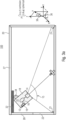
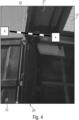
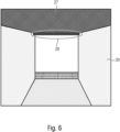
Figures 4 to 7 show exemplarily a container as thecargo repository 20 and a positioning of the occupationrate determining module 10 within thecargo repository 20. The container, for example, comprises above the door 22 ahorizontal pillar 28. As shown inFig. 7 , thepillar 28 may extend about 9 cm from theroof 27 of thecargo repository 20 towards a bottom of thecargo repository 20, i.e. toward the loading area. The occupationrate determining module 10 may be mounted to theroof 27 near thepillar 28. The dimensions of the occupationrate determining module 10 are chosen such that same does not protrude over thepillar 28. The dimensions, e.g., a height of the occupationrate determining module 10, may depend on a height of thepillar 28. - The positioning of the occupation
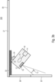
rate determining module 10 within thecargo repository 20 is shown in more detail inFig. 5a andFig. 5b .Fig. 5a shows schematically a sectional view A-A ofFig. 4 andFig. 5b shows a detailed view ofFig. 5a . As shown inFigures 5a and5b , the occupationrate determining module 10 should be placed higher than the upperhorizontal pillar 28 of an entrance side, i.e. thepillar 28 above thedoor 22, to avoid being hit by loading cargos. - As shown in
Fig. 5b , the occupationrate determining module 10 comprises thesensor 12 for detecting a state of thedoor 22 of thecargo repository 20, thecamera 14, and theprocessor 16. Thecamera 14, may comprise acamera module 142 directed to the loading area of thecargo repository 20. Theprocessor 16 may comprise a DC-DC converter and a micro controller. Further the occupationrate determining module 10 may comprise a battery, e.g., as back up, if a power source of thecargo repository 20 is temporarily unavailable or if thecargo repository 20 has no power source to which the occupationrate determining module 10 could be connected. For example, occupationrate determining module 10 may comprise the battery to supply thesensor 12, thecamera 14 and theprocessor 16 with energy. Between thehousing 18 and theroof 27 of the cargo repository 20 a hinge may be arranged for tilting and/or rotating thehousing 18. Optionally, the occupationrate determining module 10 may further comprise a proximity sensor 11 or thesensor 12 may represent a proximity sensor, which is able to detect a state of thedoor 22 by determining a distance between the sensor and a closed or openeddoor 22. Thehousing 18 may have an opening where thesensor 12 and/or the proximity sensor 11 are positioned, which is covered by a film. The film, i.e. the protective film, may function as a filter. - As shown in
Fig. 1 ,3a ,8a and8b , the occupationrate determining module 10 should be initially adjusted to be able to see all the fourcorners 21 of thecargo repository 20, e.g., using themetal plate 32 and thehinge 34. With the camera FOV, i.e. the field ofview 15, covering all the fourcorners 21 of the loading area of thecargo repository 20, e.g. a truck-trailer floor, the position of thesensor 12 for detecting the state of thedoor 22 ensures that the FOV 13 of the sensor is fully focused only on the 'Door', e.g., seeFig. 3b . This is accomplished by the predefined relative arrangement of thecamera 14 andsensor 12 within thehousing 18. Hence thesensor 12 will efficiently detect the opening and closing of thedoor 22 and automatically trigger theprocessor 16 to start the occupancy calculation. TheHorizontal pillar 28 is a short barrier within thecargo repository 20. The position of thesensor 12 within thehousing 18 will ensure that its FOV 13 does not lie within the barrier area. The hinge design when adjusted as shown inFig. 3a andFig. 3b ensures that the occupationrate determining module 10 will not protrude below thehorizontal pillar 28. Hence, it will not obstruct any equipment or vehicles moving in and out thecargo repository 20 during loading and/or unloading. The occupationrate determining module 10, for example, is adapted to be attached to a roof of a truck using existing screw holes, wherein investigations of the inventors showed that corresponding screw holes are provided in an upper left corner of the truck. - According to an embodiment, the occupation
rate determining module 10 comprises an interface or communication link to a user interface (UI) or to a receiver, like a computer, a mobile device, a memory device or the like. The interface or communication link may be configured to transmit data on a transmission medium such as a wireless transmission medium or a wired transmission medium. The transmission medium, for example, is the Internet or Bluetooth. The occupationrate determining module 10 may be configured to communicate with an app or UI via the interface, e.g., by transferring the determined occupation rate, e.g., to the UI or receiver, and or by receiving data, e.g., from the UI or receiver. The occupationrate determining module 10 may comprise a transmitter configured to transmit the determined occupation rate to an external receiver. - A user may manually mark coordinates of the loading area, e.g., of a truck trailer floor, through the UI or App. The coordinates may correspond to the four
corners 21 of the loading area of thecargo repository 20, which are in the field of view of thecamera 14 of the occupationrate determining module 10, as can be seen inFig. 8a andFig. 8b . In other words, the occupationrate determining module 10 may comprise an interface permitting a user to mark thecorners 21 of the loading area in the image taken by thecamera 14. The user may mark the four coordinates only once for the loading area of thecargo repository 20 in which the occupationrate determining module 10 is mounted. For example, the occupationrate determining module 10 may be configured to transmit an image of thecargo repository 20 in an empty state and the user may mark the fourcorners 21 of the loading area of thecargo repository 20. - The occupation
rate determining module 10 may be configured to obtain the coordinates via the interface. Optionally, the occupationrate determining module 10 may be configured to save or store the coordinates on a storage medium comprised by the occupationrate determining module 10. As can be seen inFig. 9 , theprocessor 16 of the occupationrate determining module 10 may be configured to perform aperspective transformation 200 of animage 201, e.g., a first image, taken by thecamera 14 based on the four coordinates marked by the user, e.g., to obtain aloading area image 202. Theprocessor 16, for example, is configured to transform a 3D-view of thecargo repository 20 into a 2D-view, e.g., a plan view or top view, of the loading area of thecargo repository 20 using theperspective transformation 200. Thus, instead of showing an inside of thecargo repository 20 out of the view of thecamera 14, e.g. including walls and/or a roof of thecargo repository 20 together with the loading area, theloading area image 202 shows the inside of thecargo repository 20 from above, i.e. the loading area from above. - The
image 201 undergoing theperspective transformation 200, for example, may correspond to the image taken by thecamera 14 when thesensor 12 detected the change of the state of thedoor 22. Alternatively, theprocessor 16 may be configured to select theimage 201, which should undergo theperspective transformation 200, out of multiple images taken during a time interval comprising the time instant at which the change of the state of thedoor 22 is detected or taken during a time interval preceding or following the time instant at which the change of the state of thedoor 22 is detected, e.g., theimage 201 may correspond to the best brightness image of the multiple images. - The four coordinates, e.g., of the
corners 21, may be determined by the user only once for an empty state of thecargo repository 20 and theprocessor 16 may be configured to use always the same four coordinate at theperspective transformations 200. Alternatively, the four coordinates may be updated after a certain time interval or may be determined by the user for eachimage 201 to be transformed by theperspective transformation 200 individually. - The
processor 16 may be configured to transform 210 theloading area image 202, e.g., a second image, to a grayscaleloading area image 203, e.g., a third image, and perform afiltering 220 of the grayscaleloading area image 203 to emphasize edges and, e.g., obtain an edge emphasizedloading area image 204, e.g., a fourth image. Further, theprocessor 16 may be configured to perform anedge detection 230. Theedge detection 230 may be applied to the edge emphasizedloading area image 204 to obtain an edge detectedloading area image 205, e.g., a fifth image. In addition, theprocessor 16 may be configured to perform a line detection and filling 240, e.g., to obtain a cargo identifiedloading area image 206, e.g., a sixth image, based on the edge detectedloading area image 205. Theprocessor 16 may be configured to determine 250 the occupation rate, e.g., calculate a fill rate, based on the cargo identifiedloading area image 206. - It may not be necessary to perform all steps shown in
Fig. 9 . The processor, for example, may be configured to perform theperspective transformation 200 of theimage 201 taken by thecamera 14 to a transformed image, i.e. theloading area image 202, representing a top view of the loading area, to perform theedge detection 230 using the transformed image, to determine filled regions of the loading area, e.g., see cargo identifiedloading area image 206, based on the detected edges and to determine 250 the occupation rate using the determined filled regions. This has the advantage that the occupation rate can be determined very efficiently. As described above and shown inFig. 9 , additionally, theprocessor 16 may be configured to, before performing theedge detection 230, transform 210 the transformed image to grayscale to generate a grayscale image, i.e. the grayscaleloading area image 203, and/or to filter 220 the transformed image or the grayscale image to emphasize edges in the transformed image or the grayscale image. Thisoptional transformation 210 andoptional filtering 220 enhances theedge detection 230 and improves therefore an accuracy and an efficiency at the occupation rate determination. - In the example shown in
Fig. 9 the output, i.e. the determined occupation rate, would be that two out of 33 cargo placement areas are occupied. According to an embodiment, theprocessor 16 may be configured to determine the floor coverage of the loading area as the occupation rate, i.e., the ratio of the floor which is covered by cargo independent of the height of the specific cargo. For example, independent of whether low cargo or high cargo is arranged over the whole loading area of thecargo repository 20, an occupation rate of 100% would be obtained. The invention represents a mechanical architecture for a system that calculates the empty area of a floor space of a cargo repository, like a truck. For example, the occupation rate may be a percentage representing a ratio of an area filled with cargo to an area not filled with cargo within the loading area, or may be the area filled with cargo within the loading area or may be the area not filled with cargo. - According to an embodiment, the algorithm starts from the assumption that the
cargo repository 20 is filled up with cargo starting from the part most distant from thecamera 14 towards thecamera 14, i.e. starting from the back of thecargo repository 20, i.e. an end of thecargo repository 20 opposite to thedoor 22, towards thedoor 22. Theprocessor 16, for example, is configured to assume that no empty spaces are between cargo behind an edge detected closest to thecamera 14, i.e. that the loading area is completely filled with cargo behind the edge detected closest to thecamera 14, i.e. without empty spaces on a floor of thecargo repository 20. Thus, theprocessor 16, for example, is configured to completely fill 240 an area behind the edge detected closest to thecamera 14, e.g., incamera direction 300. Thecamera direction 300 may be defined as a direction from thedoor 22 of thecargo repository 20 to an opposite side of thecargo repository 20. The edge detected closest to thecamera 14 may be an edge perpendicular to thecamera direction 300. - Alternatively, the
processor 16 is configured to detect incamera direction 300 one or more further edges, i.e. edges perpendicular to thecamera direction 300. Thus, it is possible to detect an empty space behind cargo or between two cargoes. Theprocessor 16, for example, assumes that an area between an edge detected closest to thecamera 14 and a subsequent edge incamera direction 300 represents cargo and, for example, is to be filled 240, and that an area between the subsequent edge and the back of thecargo repository 20 or a further subsequent edge is not to be filled. Theprocessor 16, for example, is configured to, incamera direction 300, alternately fill in or not fill in areas between an edge and a subsequent edge starting at the edge detected closest to thecamera 14, wherein filled in areas represent cargo and not filled in areas represent empty spaces. - In case no edge is detected by the
processor 16, theprocessor 16 may be configured to compare a color or structure of the loading area within theloading area image 202 with a reference image showing thecargo repository 20 in an empty state. If the color or structure of the loading area within theloading area image 202 and within a reference image is the same, theprocessor 16 may be configured to determine an occupation rate of 0 % and if the color or structure of the loading area within theloading area image 202 and within the reference image is not the same, theprocessor 16 may be configured to determine an occupation rate of 100 %. - Alternatively, if no edge is detected by the
processor 16 within theloading area image 202, theprocessor 16 may be configured to indicate that the calculation of the occupation area is not possible or not sure and/or theprocessor 16 may be configured to indicate that thecargo repository 20 is empty, e.g., it may return 0/33, wherein the first number, i.e. 0, indicates a number of areas occupied by cargo and the second number, i.e. 33, indicates a capacity of thecargo repository 20, e.g. a maximum available number of areas for cargo. The second number depends on thecargo repository 20, i.e. the second number may be different fordifferent cargo repositories 20. This, for example, may be the case, if theloading area image 202 is taken by thecamera 14 at a low light condition within thecargo repository 20. - According to an embodiment, the algorithm is based on the assumption that the
cargo repository 20 is filled up with cargo of linear shape, i.e. of cargo with uniform dimensions, especially with regard to a dimension perpendicular to the loading area, i.e. the height of the cargo. Thus, theprocessor 16, for example, is configured to assume that all cargo behind an edge detected closest to thecamera 14 has the same height. - The height of individual cargo within the
cargo repository 20 may not be relevant for the occupationrate determining module 10, since same may only determine a floor coverage of the loading area as the occupation rate. Further, it may be irrelevant whether first cargo is positioned over second cargo within thecargo repository 20, i.e. whether cargo is stacked or not. It is also not relevant whether lower cargo is arranged behind higher cargo and is hidden from thecamera 14, since theprocessor 16 may be configured to assume that, in camera direction, a detected edge closest to thecamera 14 represents an end of an occupied area, i.e. an area occupied by cargo. - All calculation of the occupation rate is done within the occupation
rate determining module 10 by a microcomputer or a microprocessor, i.e. theprocessor 16, which is programmed accordingly. - The occupation
rate determining module 10 and/or thesystem 100, e.g., as described with regard tofigures 1 to 9 , can comprise one or more features and/or functionalities of the following sections "Mechanical Structure and Emplacement", "Sensing" and "Image Processing" individually or in combination. -
- The
camera 14, one or more processors, e.g., comprising theprocessor 16, and one or more sensors, e.g., comprising thesensor 12, are mounted in one module, i.e. the occupationrate determining module 10, together. Thus, the module installation is done in one place. (seeFig. 1-3b ) - The
module 10, for example, is emplaced onto anywhere of the roof edge of a truck, e.g., of thecargo repository 20, where a loading gate exists for image processing and detecting the door open/close. It is not necessary to install themodule 10 in an exact location provided that it is mounted to a roof edge of a cargo repository, like a truck, where, e.g., a loading gate exists, and that thecamera 14 is visible to scope the fourcorners 21 of the loading area, e.g., the truck floor (e.g., seeFig. 4 andFig. 6 ) - Place the
module 10 close to thedoor 22 to detect the door's open/close status. Themodule 10 should be placed within a distance from thedoor 22 where thesensor 12, e.g., a proximity sensor, can detect thedoor 22. The distance should be in the range of 2 cm to 20 cm, 2 cm to 15 cm or 5 cm to 15 cm, like at a distance of 10cm. (seeFig. 1 andFig. 3b ) - Truck inside, i.e. the inside of the
cargo repository 20, does not need to be modified for themodule 10 installation because themodule 10 can be installed by a bolt or multiple bolts that the truck inherently owns. This enables an easy installation. (seeFig. 2a and2b ) - The system module height should be lower/smaller than 9 cm, otherwise the
module 10 may be hit by loading cargo. In other words, place themodule 10 higher than an upper horizontal pillar of an entrance side of thecargo repository 20 to avoid being hit by loading cargos. (seeFig. 5a ,5b and7 ) - The
module 10 may have its own battery to cover the period when there is no power supply from the truck's own power source, i.e. from the power source of thecargo repository 20. The truck's own power source is sometimes not available -
- The main purpose of the
sensor 12 is reducing power consumption because the power source is limited in acargo repository 20 like a truck. (Truck's battery and module's battery) - The
sensor 12 contributes to reducing the power consumption by limiting occupancy calculation only around the door open-close timing - To trigger the image processing automatically, several types of sensors may be comprised by the occupation rate determining module 10: Proximity sensor or TOF sensor, Ambient light sensor and Accelerometer to detect a status of the truck. (For example, door-open/close, truck is moving/parking etc.; see
Fig. 5b ) -
- Using a
single camera 14 and aprocessor 16 to calculate the empty area of the loading area, e.g., the truck floor - The entire truck floor should be visible by the
camera 14 of themodule 10. Place thecamera 14 where it can see all the fourcorners 21 of the loading area, e.g., a truck floor, for the image processing algorithm (seeFig. 1 ,Fig. 3a ,Fig. 8a and8b ) - In addition, the user may regularly calibrate the system that specifies the 4
corners 21 of the truck floor (seeFig. 8a and8b ) - The
system 100 may return 'calculation is impossible, or calculation result is not sure' under complex situation. For example, under dark lightning condition, irregular cargo in alignment, shape, or color etc., - Currently by using a
single camera 14 and aprocessor 16, empty floor calculation can be executed (seeFig. 9 ). However, the calculation may work under the following specific conditions:- Cargo must be loaded from the back
- The shape of the load must be linear
- The inside of the truck must be enough bright for the camera to see the corners of the floor
- The invention reduces power consumption by limiting occupancy calculation only around the door open-close timing that, for example, relates to the end of loading cargos
- This technology could be used in various areas, especially for object detection and space calculation that changes over time. For example, container occupancy, elevator crowdedness and garbage bin full or not.
-
Fig. 10 shows amethod 400 of determining an occupancy of a cargo repository equipped with a door. Themethod 400, for example, uses a herein described occupationrate determining module 10. Themethod 400 is based on the same considerations as the above-describedsystem 100 and occupationrate determining module 10. Themethod 400 can, by the way, be completed with all features and/or functionalities, which are also described with regard to thesystem 100 and/or the occupationrate determining module 10. For example, corresponding method steps may be derivable from features an and/or functionalities described with regard to thesystem 100 and/or the occupationrate determining module 10. - The
method 400 comprises taking 410 an image of a loading area of the cargo repository using a camera having a field of view including all corners of the loading area and detecting 420 a change of the state of the door of the cargo repository from an open state to a closed state and/or from a closed state to an open state. Optionally, the taking 410 of the image may be triggered 412 by the detected change of the state of the door or may be triggered manually or remotely, e.g., by a user. Upon detecting the change of the state of the door or a trigger by a user, themethod 400 comprises determining 430, based on the image taken by the camera, the occupation rate of the cargo repository. Further, themethod 400 comprises not determining 430 the occupation rate of the cargo repository unless a change of the state of the door or a trigger by a user is detected 420. - Optionally, the occupation
rate determining module 10 may comprise an interface to a cloud or app, such as a smartphone app. The triggering by the user may be performed by a remote user, e.g., via a user interface, such as a smartphone app, e.g., a cloud based smartphone app. - Optionally, the
method 400 comprises adjusting the orientation of the camera so that the field of view includes all corners of the loading area of the cargo repository, marking the corners of the loading area of the cargo repository, and determining 430 the occupation rate of the cargo repository using the image taken 410 by the camera in which the corners of the loading area are marked.
Claims (15)
- An occupation rate determining module (10) configured to determine an occupancy of a cargo repository (20) equipped with a door (22), the occupation rate determining module (10) comprising:a sensor (12) configured to detect a state of the door (22) of the cargo repository (20);a camera (14) having a field of view (15) including all corners (21) of a loading area of the cargo repository (20);a processor (16) configured to determine, based on an image (201) taken by the camera (14), the occupation rate of the cargo repository (20) when the sensor (12) detects a change of the state of the door (22) from an open state to a closed state and/or from a closed state to an open state,a housing (18) accommodating the sensor (12), the camera (14) and the processor (16).
- The occupation rate determining module (10) of claim 1, wherein the processor (16) is configured to determine the occupation rate based on a best brightness image in a last capturing window period.
- The occupation rate determining module (10) of claim 1 or 2 comprising a mounting device (30) configured to mount the housing (18) to the cargo repository (20) to arrange the camera (14) with the field of view (15) including all corners (21) of the loading area of the cargo repository (20).
- The occupation rate determining module (10) of claim 3, wherein the mounting device (30) comprises a plate member (32) to be fixed to the cargo repository (20) and a coupling member coupling the housing to the plate member so that the housing is arranged at a specific rotation angle and tilt angle, optionally, the plate member (32) comprises bores adapted to permit the plate member (32) to be fixed to the cargo repository (20) using screw holes provided in the roof of the cargo repository (20).
- The occupation rate determining module (10) of one of claims 1 to 4, wherein the sensor (12) is an object detection sensor, such as an ultrasonic sensor or a time of flight sensor, wherein the housing (18) has an opening configured to pass light of the time of flight sensor toward the door (22) of the cargo repository (20), wherein a protective film (19) transmissive for the light of the time of flight sensor covers the opening of the housing (18).
- The occupation rate determining module (10) of one of claims 1 to 5, wherein the processor (16) is configured to perform a perspective transformation (200) of the image (201) taken by the camera (14) to a transformed image (202) representing a top view of the loading area, to perform an edge detection (230) using the transformed image (202), to determine filled regions of the loading area based on the detected edges and to determine the occupation rate using the determined filled regions.
- The occupation rate determining module (10) of claim 6, wherein the processor (16) is configured to, before performing the edge detection (230), transform (210) the transformed image (202) to grayscale to generate a grayscale image (203), and/or to filter (220) the transformed image (202) or the grayscale image (203) to emphasize edges in the transformed image (202) or the grayscale image (203).
- The occupation rate determining module (10) of one of claims 1 to 7, comprising a transmitter configured to transmit the determined occupation rate to an external receiver and/or a battery to supply the sensor (12), the camera (14) and the processor (16) with energy.
- The occupation rate determining module (10) of one of claims 1 to 8, comprising an interface permitting a user to mark the corners (21) of the loading area in the image taken by the camera (14).
- A system (100) comprising a cargo repository (20) and the occupation rate determining module (10) of one of claims 1 to 9, wherein the housing (18) of the occupation rate determining module (10) is mounted to the cargo repository (20) to direct the sensor (12) to the door (22) of the cargo repository (20) and to direct the camera (14) to the loading area of the cargo repository (20) with the field of view including all corners (21) of the loading area of the cargo repository (20).
- The system (100) of claim 10, wherein the cargo repository (20) comprises a the roof and a horizontal pillar (28) between the roof and the door (22) of the cargo repository (20), wherein the occupation rate determining module (10) is mounted in the cargo repository (20) adjacent to the horizontal pillar (28) so as not to protrude beyond a lower edge of the horizontal pillar.
- The system (100) of claim 10 or 11, wherein the cargo repository (20) is a trailer or a truck hold.
- The system (100) of claim 12, wherein the occupation rate determining module (10) is mounted to the roof of the cargo repository (20) using standard screw holes in the roof of the cargo repository (20), which are not specifically dedicated for mounting the occupation rate determining module (10).
- A method (400) of determining an occupancy of a cargo repository equipped with a door using the occupation rate determining module according to one of claims 1 to 9, the method comprising:taking (410) an image of a loading area of the cargo repository using a camera having a field of view including all corners of the loading area;detecting (420) a change of the state of the door of the cargo repository from an open state to a closed state and/or from a closed state to an open state;upon detecting the change of the state of the door or a trigger by a user, determining (430), based on the image taken by the camera, the occupation rate of the cargo repository; andnot determining (430) the occupation rate of the cargo repository unless a change of the state of the door or a trigger by a user is detected.
- The method (400) of claim 14 comprising:adjusting the orientation of the camera so that the field of view includes all corners of the loading area of the cargo repository;marking the corners of the loading area of the cargo repository; anddetermining (430) the occupation rate of the cargo repository using the image taken by the camera in which the corners of the loading area are marked.
Priority Applications (1)
| Application Number | Priority Date | Filing Date | Title |
|---|---|---|---|
| EP23168694.0A EP4451187A1 (en) | 2023-04-19 | 2023-04-19 | Occupation rate determining module, system and method of determining an occupancy of a cargo repository |
Applications Claiming Priority (1)
| Application Number | Priority Date | Filing Date | Title |
|---|---|---|---|
| EP23168694.0A EP4451187A1 (en) | 2023-04-19 | 2023-04-19 | Occupation rate determining module, system and method of determining an occupancy of a cargo repository |
Publications (1)
| Publication Number | Publication Date |
|---|---|
| EP4451187A1 true EP4451187A1 (en) | 2024-10-23 |
Family
ID=86185231
Family Applications (1)
| Application Number | Title | Priority Date | Filing Date |
|---|---|---|---|
| EP23168694.0A Withdrawn EP4451187A1 (en) | 2023-04-19 | 2023-04-19 | Occupation rate determining module, system and method of determining an occupancy of a cargo repository |
Country Status (1)
| Country | Link |
|---|---|
| EP (1) | EP4451187A1 (en) |
Citations (4)
| Publication number | Priority date | Publication date | Assignee | Title |
|---|---|---|---|---|
| US20070040677A1 (en) | 2005-08-17 | 2007-02-22 | Blair Herbert W Jr | Detecting cargo status and load activity |
| US20130342653A1 (en) * | 2012-06-20 | 2013-12-26 | Honeywell International Inc. | Cargo sensing |
| US20190271582A1 (en) * | 2018-01-22 | 2019-09-05 | Blackberry Limited | Method and system for cargo load detection |
| US20220318963A1 (en) * | 2021-04-01 | 2022-10-06 | Xirgo Technologies, Llc | Gateway device for volumetric sensing |
-
2023
- 2023-04-19 EP EP23168694.0A patent/EP4451187A1/en not_active Withdrawn
Patent Citations (4)
| Publication number | Priority date | Publication date | Assignee | Title |
|---|---|---|---|---|
| US20070040677A1 (en) | 2005-08-17 | 2007-02-22 | Blair Herbert W Jr | Detecting cargo status and load activity |
| US20130342653A1 (en) * | 2012-06-20 | 2013-12-26 | Honeywell International Inc. | Cargo sensing |
| US20190271582A1 (en) * | 2018-01-22 | 2019-09-05 | Blackberry Limited | Method and system for cargo load detection |
| US20220318963A1 (en) * | 2021-04-01 | 2022-10-06 | Xirgo Technologies, Llc | Gateway device for volumetric sensing |
Similar Documents
| Publication | Publication Date | Title |
|---|---|---|
| US11185183B2 (en) | Package receptacle having a locking mechanism | |
| US20240270385A1 (en) | Drone Delivery System | |
| US5089972A (en) | Moored ship motion determination system | |
| KR102715334B1 (en) | Apparatus and method for tracking air cargo | |
| US11679726B2 (en) | Vehicle sensor systems | |
| EP3514573B1 (en) | Method and system for cargo load detection | |
| US11835847B2 (en) | Surveillance device | |
| US20160328961A1 (en) | Vehicle detection system | |
| KR102334984B1 (en) | A truck equipped with height controlled container | |
| CA3036565C (en) | Rf antenna sector monitoring device and method | |
| KR20210097241A (en) | System for integrated management of smart container for optimizing port logistics | |
| EP4451187A1 (en) | Occupation rate determining module, system and method of determining an occupancy of a cargo repository | |
| US12152411B2 (en) | Lock sensor assembly | |
| US12182759B2 (en) | Sensor assembly for equipment for aiding the traceability of agri-food products | |
| US11601781B2 (en) | Inspection tracking system | |
| KR20230083806A (en) | Movable type surveillance camera apparatus | |
| JP7037155B2 (en) | Container damage inspection equipment and container damage inspection method | |
| CN117647780A (en) | Calibration system and calibration method for vehicle sensors | |
| RU160926U1 (en) | DEVICE FOR OPERATIONAL PLACEMENT OF PHOTO RADAR ON A VEHICLE | |
| KR102249033B1 (en) | Atmospheric chemical detection equipment installable vehicle | |
| EP4246273B1 (en) | Modular sensor kit for the collection of vehicle-related data | |
| KR102094600B1 (en) | Apparatus for managing parking lots using used mobile phones | |
| KR102637714B1 (en) | loading ststus information supply system for loading box of truck | |
| EP4260025B1 (en) | Sealed sensor assembly for an equipment for aiding traceability of agri-food products | |
| KR20250152353A (en) | Mobile radar test system and radar test method using the same |
Legal Events
| Date | Code | Title | Description |
|---|---|---|---|
| PUAI | Public reference made under article 153(3) epc to a published international application that has entered the european phase |
Free format text: ORIGINAL CODE: 0009012 |
|
| STAA | Information on the status of an ep patent application or granted ep patent |
Free format text: STATUS: THE APPLICATION HAS BEEN PUBLISHED |
|
| AK | Designated contracting states |
Kind code of ref document: A1 Designated state(s): AL AT BE BG CH CY CZ DE DK EE ES FI FR GB GR HR HU IE IS IT LI LT LU LV MC ME MK MT NL NO PL PT RO RS SE SI SK SM TR |
|
| STAA | Information on the status of an ep patent application or granted ep patent |
Free format text: STATUS: THE APPLICATION IS DEEMED TO BE WITHDRAWN |
|
| 18D | Application deemed to be withdrawn |
Effective date: 20250424 |