EP4451028A1 - Optical fiber cable - Google Patents
Optical fiber cable Download PDFInfo
- Publication number
- EP4451028A1 EP4451028A1 EP22907534.6A EP22907534A EP4451028A1 EP 4451028 A1 EP4451028 A1 EP 4451028A1 EP 22907534 A EP22907534 A EP 22907534A EP 4451028 A1 EP4451028 A1 EP 4451028A1
- Authority
- EP
- European Patent Office
- Prior art keywords
- optical fiber
- optical fibers
- fiber cable
- tensile strength
- cable
- Prior art date
- Legal status (The legal status is an assumption and is not a legal conclusion. Google has not performed a legal analysis and makes no representation as to the accuracy of the status listed.)
- Pending
Links
- 239000013307 optical fiber Substances 0.000 title claims abstract description 212
- 239000011521 glass Substances 0.000 claims abstract description 33
- 239000000835 fiber Substances 0.000 claims abstract description 8
- 238000005452 bending Methods 0.000 claims description 24
- 230000008878 coupling Effects 0.000 claims description 24
- 238000010168 coupling process Methods 0.000 claims description 24
- 238000005859 coupling reaction Methods 0.000 claims description 24
- 229920005989 resin Polymers 0.000 description 34
- 239000011347 resin Substances 0.000 description 34
- 239000011247 coating layer Substances 0.000 description 15
- 238000005253 cladding Methods 0.000 description 11
- 238000010521 absorption reaction Methods 0.000 description 10
- XLYOFNOQVPJJNP-UHFFFAOYSA-N water Substances O XLYOFNOQVPJJNP-UHFFFAOYSA-N 0.000 description 10
- 229920002430 Fibre-reinforced plastic Polymers 0.000 description 7
- 239000011151 fibre-reinforced plastic Substances 0.000 description 7
- 230000001965 increasing effect Effects 0.000 description 6
- 230000000052 comparative effect Effects 0.000 description 5
- 239000010410 layer Substances 0.000 description 5
- 239000000463 material Substances 0.000 description 5
- 230000004048 modification Effects 0.000 description 4
- 238000012986 modification Methods 0.000 description 4
- RNFJDJUURJAICM-UHFFFAOYSA-N 2,2,4,4,6,6-hexaphenoxy-1,3,5-triaza-2$l^{5},4$l^{5},6$l^{5}-triphosphacyclohexa-1,3,5-triene Chemical compound N=1P(OC=2C=CC=CC=2)(OC=2C=CC=CC=2)=NP(OC=2C=CC=CC=2)(OC=2C=CC=CC=2)=NP=1(OC=1C=CC=CC=1)OC1=CC=CC=C1 RNFJDJUURJAICM-UHFFFAOYSA-N 0.000 description 3
- VYPSYNLAJGMNEJ-UHFFFAOYSA-N Silicium dioxide Chemical compound O=[Si]=O VYPSYNLAJGMNEJ-UHFFFAOYSA-N 0.000 description 3
- 239000003795 chemical substances by application Substances 0.000 description 3
- 239000003063 flame retardant Substances 0.000 description 3
- 239000011342 resin composition Substances 0.000 description 3
- 239000004698 Polyethylene Substances 0.000 description 2
- XUIMIQQOPSSXEZ-UHFFFAOYSA-N Silicon Chemical compound [Si] XUIMIQQOPSSXEZ-UHFFFAOYSA-N 0.000 description 2
- 239000002131 composite material Substances 0.000 description 2
- 230000000694 effects Effects 0.000 description 2
- 229910052809 inorganic oxide Inorganic materials 0.000 description 2
- 239000002245 particle Substances 0.000 description 2
- 230000002093 peripheral effect Effects 0.000 description 2
- 229920000728 polyester Polymers 0.000 description 2
- 229920000573 polyethylene Polymers 0.000 description 2
- 229910052710 silicon Inorganic materials 0.000 description 2
- 239000010703 silicon Substances 0.000 description 2
- OKTJSMMVPCPJKN-UHFFFAOYSA-N Carbon Chemical compound [C] OKTJSMMVPCPJKN-UHFFFAOYSA-N 0.000 description 1
- 229920000106 Liquid crystal polymer Polymers 0.000 description 1
- 239000004977 Liquid-crystal polymers (LCPs) Substances 0.000 description 1
- 239000006087 Silane Coupling Agent Substances 0.000 description 1
- 239000000654 additive Substances 0.000 description 1
- 230000000996 additive effect Effects 0.000 description 1
- WNROFYMDJYEPJX-UHFFFAOYSA-K aluminium hydroxide Chemical compound [OH-].[OH-].[OH-].[Al+3] WNROFYMDJYEPJX-UHFFFAOYSA-K 0.000 description 1
- 239000004760 aramid Substances 0.000 description 1
- 229920003235 aromatic polyamide Polymers 0.000 description 1
- 229910052799 carbon Inorganic materials 0.000 description 1
- 239000011248 coating agent Substances 0.000 description 1
- 238000000576 coating method Methods 0.000 description 1
- 239000000470 constituent Substances 0.000 description 1
- KPUWHANPEXNPJT-UHFFFAOYSA-N disiloxane Chemical class [SiH3]O[SiH3] KPUWHANPEXNPJT-UHFFFAOYSA-N 0.000 description 1
- MHCLJIVVJQQNKQ-UHFFFAOYSA-N ethyl carbamate;2-methylprop-2-enoic acid Chemical compound CCOC(N)=O.CC(=C)C(O)=O MHCLJIVVJQQNKQ-UHFFFAOYSA-N 0.000 description 1
- UHESRSKEBRADOO-UHFFFAOYSA-N ethyl carbamate;prop-2-enoic acid Chemical compound OC(=O)C=C.CCOC(N)=O UHESRSKEBRADOO-UHFFFAOYSA-N 0.000 description 1
- 238000001125 extrusion Methods 0.000 description 1
- 239000004744 fabric Substances 0.000 description 1
- 230000002209 hydrophobic effect Effects 0.000 description 1
- 230000001939 inductive effect Effects 0.000 description 1
- 239000003999 initiator Substances 0.000 description 1
- 229910010272 inorganic material Inorganic materials 0.000 description 1
- 239000011147 inorganic material Substances 0.000 description 1
- VTHJTEIRLNZDEV-UHFFFAOYSA-L magnesium dihydroxide Chemical compound [OH-].[OH-].[Mg+2] VTHJTEIRLNZDEV-UHFFFAOYSA-L 0.000 description 1
- 239000000347 magnesium hydroxide Substances 0.000 description 1
- 229910001862 magnesium hydroxide Inorganic materials 0.000 description 1
- 239000000178 monomer Substances 0.000 description 1
- 230000003287 optical effect Effects 0.000 description 1
- 125000000951 phenoxy group Chemical group [H]C1=C([H])C([H])=C(O*)C([H])=C1[H] 0.000 description 1
- 229920003023 plastic Polymers 0.000 description 1
- 239000004033 plastic Substances 0.000 description 1
- -1 polyethylene Polymers 0.000 description 1
- 229920005672 polyolefin resin Polymers 0.000 description 1
- 239000004800 polyvinyl chloride Substances 0.000 description 1
- 239000000843 powder Substances 0.000 description 1
- 239000011241 protective layer Substances 0.000 description 1
- 235000012239 silicon dioxide Nutrition 0.000 description 1
- 239000002344 surface layer Substances 0.000 description 1
- 229920001187 thermosetting polymer Polymers 0.000 description 1
- 125000000391 vinyl group Chemical group [H]C([*])=C([H])[H] 0.000 description 1
- 229920002554 vinyl polymer Polymers 0.000 description 1
Images

Classifications
-
- G—PHYSICS
- G02—OPTICS
- G02B—OPTICAL ELEMENTS, SYSTEMS OR APPARATUS
- G02B6/00—Light guides; Structural details of arrangements comprising light guides and other optical elements, e.g. couplings
- G02B6/44—Mechanical structures for providing tensile strength and external protection for fibres, e.g. optical transmission cables
-
- G—PHYSICS
- G02—OPTICS
- G02B—OPTICAL ELEMENTS, SYSTEMS OR APPARATUS
- G02B6/00—Light guides; Structural details of arrangements comprising light guides and other optical elements, e.g. couplings
- G02B6/02—Optical fibres with cladding with or without a coating
-
- G—PHYSICS
- G02—OPTICS
- G02B—OPTICAL ELEMENTS, SYSTEMS OR APPARATUS
- G02B6/00—Light guides; Structural details of arrangements comprising light guides and other optical elements, e.g. couplings
- G02B6/02—Optical fibres with cladding with or without a coating
- G02B6/02042—Multicore optical fibres
-
- G—PHYSICS
- G02—OPTICS
- G02B—OPTICAL ELEMENTS, SYSTEMS OR APPARATUS
- G02B6/00—Light guides; Structural details of arrangements comprising light guides and other optical elements, e.g. couplings
- G02B6/44—Mechanical structures for providing tensile strength and external protection for fibres, e.g. optical transmission cables
- G02B6/4401—Optical cables
- G02B6/4403—Optical cables with ribbon structure
Definitions
- the present disclosure relates to an optical fiber cable.
- an optical fiber cable there is a slot type cable in which a plurality of optical fibers are accommodated in a slot rod and covered with a sheath.
- a slotless type cable in which the slot rod is omitted and a plurality of optical fibers are mounted in a cable sheath at a high density.
- a single-core fiber including one core and a multi-core fiber including a plurality of cores are known (for example, Patent Literature 1).
- Patent Literature 1 JP2015-052704A
- An optical fiber cable including:
- the slot type cable includes the slot rod, it is difficult to mount the optical fibers at a high density.
- the slotless type cable there is also a limit to increasing the density of the optical fibers with the currently commonly used optical fibers having a glass diameter of 125 ⁇ m and a core wire diameter of 250 ⁇ m.
- the intermittent coupling type optical fiber ribbon may be used as the plurality of optical fibers. By using the intermittent coupling type optical fiber ribbon, it is possible to mount the optical fibers in the optical fiber cable at a higher density.
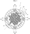
- FIG. 1 is a cross-sectional view of an optical fiber cable 2 according to an embodiment of the present disclosure.
- the optical fiber cable 2 includes a plurality of optical fibers that are in the form of a plurality of optical fiber ribbons 21, a water absorption tape 22 for example, a cable sheath 23 (a sheath), at least one tensile strength member 24, at least one tear string 25, and a plurality of protrusions 26 for example.
- the cable outer diameter of the optical fiber cable 2 is, for example, 20 mm.
- the tensile strength of the optical fiber cable 2 is 1300 N or more.
- the water absorption tape 22 is longitudinally or spirally wrapped around the whole of the plurality of optical fiber ribbons 21, for example.
- the water absorption tape 22 is, for example, a tape subjected to water absorption processing by applying a water absorption powder to a base fabric made of polyester or the like.
- the thickness of the water absorption tape 22 is, for example, 0.3 mm.
- the optical fiber cable 2 includes the water absorption tape 22.
- the optical fiber cable 2 may not include the water absorption tape 22.
- the cable sheath 23 covers the periphery of the water absorption tape 22. In other words, the cable sheath 23 covers the plurality of optical fiber ribbons 21 from the outside.
- the cable sheath 23 accommodates the plurality of optical fiber ribbons 21 (the plurality of optical fibers).
- a plurality of the tensile strength members 24 are embedded in the layer of the cable sheath 23.
- the thickness of the cable sheath 23 is, for example, 1.5 mm.
- the cable sheath 23 is made of, for example, a flame-retardant material.
- the flame-retardant material examples include a vinyl resin such as polyvinyl chloride (PVC) containing a flame-retardant inorganic material such as magnesium hydroxide or aluminum hydroxide, and a polyolefin resin such as polyethylene (PE).
- PVC polyvinyl chloride
- PE polyethylene
- the cable sheath 23 may contain a release agent.
- the release agent include silicon-based release agents such as silicon and siloxane.
- the tensile strength members 24 are arranged in the longitudinal direction of the optical fiber cable 2 along the plurality of optical fiber ribbons 21.
- the diameter of the tensile strength member 24 is, for example, 0.5 mm.
- the tensile strength member 24 is made of fiber reinforced plastic (FRP) such as aramid FRP, glass FRP, or carbon FRP.
- the tensile strength member 24 may be made of a liquid crystal polymer.
- the tensile strength member 24 is preferably non-inductive.
- the fiber-reinforced plastic (FRP) is generally a combustible material. From the viewpoint of improving the flame retardance of the entire optical fiber cable 2, the tensile strength member 24 is preferably provided not near the surface layer of the cable sheath 23 but near the center of the optical fiber cable 2, inside the cable sheath 23.
- the tensile strength member 24 has a circular cross section in the radial direction.
- eight tensile strength members 24 are embedded in the layer of the cable sheath 23.
- the eight tensile strength members 24 form pairs of two tensile strength members.
- the paired two tensile strength members 24 are collectively referred to as a tensile strength member set 240.
- the four tensile strength member sets 240 are separated from each other and embedded in the layer of the cable sheath 23.
- the four tensile strength member sets 240 are spaced apart from each other at equal intervals.
- the tensile strength member sets 240 are provided, one by one, at positions facing each other across the center of the optical fiber cable 2, in the cross section of the optical fiber cable 2 in the radial direction.
- the tensile strength member sets 240 are provided such that a straight line connecting two tensile strength member sets 240 facing each other and another straight line connecting the other two tensile strength member sets 240 facing each other are orthogonal to each other.
- the tear strings 25 are provided to tear the cable sheath 23.
- the tear strings 25 are arranged along the plurality of optical fiber ribbons 21 in the longitudinal direction of the optical fiber cable 2, in the layer of the cable sheath 23.
- two tear strings 25 are provided.
- Each of the tear strings 25 is located substantially in the middle of the adjacent tensile strength member sets 240.
- the two tear strings 25 face each other.
- the four tensile strength member sets 240 are arranged line-symmetrically with respect to a straight line L connecting centers of the tear strings 25 and the optical fiber cable 2, in the cable cross-sectional view.
- the operator can tear the cable sheath 23 in the longitudinal direction by pulling out the tear string 25 and take out the optical fiber ribbon 21.
- the tear string 25 has a fiber shape, and is made of, for example, a plastic material (for example, polyester) resistant to tension.
- a plurality of (two in the present embodiment) protrusions 26 are provided.
- the two protrusions 26 are provided along the longitudinal direction of the optical fiber cable 2.
- the protrusions 26 may be provided continuously along the longitudinal direction, or may be provided intermittently. Further, the two protrusions 26 are provided to, for example, facing each other across the center of the optical fiber cable 2 in the circumferential direction of the outer peripheral portion of the cable sheath 23, in the cross section of the optical fiber cable 2 in the radial direction.
- the protrusion 26 is provided on the straight line L connecting the centers of the tear strings 25 and the optical fiber cable 2.
- the protrusion 26 is formed on the outer peripheral portion of the cable sheath 23 in the state of protruding in the radial direction of the optical fiber cable 2.
- the protrusion 26 has a curved surface 26a in a protruding direction thereof.
- the protrusion 26 is formed integrally with the cable sheath 23 by extrusion molding.
- the optical fiber cable 2 includes the two protrusions 26.
- the optical fiber cable 2 may not include the protrusion 26.
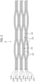
- FIG. 2 is a partially exploded view showing the optical fiber ribbon 21 in the longitudinal direction.
- the optical fiber ribbon 21 is an intermittent coupling type optical fiber ribbon.
- a coupling portion 212 in which adjacent optical fibers of some or all of the plurality of optical fibers 211A to 211L are coupled, and a non-coupling portion 213 in which the adjacent optical fibers are not coupled are intermittently provided in the longitudinal direction.
- the bending rigidity of each of the optical fibers 211A to 211L is 0.25 N ⁇ mm 2 or more.
- the 12 optical fibers 211A to 211L are arranged in parallel.
- the portion where the coupling portion 212 and the non-coupling portion 213 are intermittently provided may be between a part of the optical fibers (intermittently every two cores), or may be between all the optical fibers (intermittently every one core).
- the optical fiber ribbon 21 shown in FIG. 2 is intermittent every two cores, and the non-coupling portion 213 is not provided between the optical fibers 211A and 211B, 211C and 211D, 211E and 211F, 211G and 211H, 211I and 211J, and 211K and 211L.
- the coupling portion 212 in the optical fiber ribbon 21 is formed by applying a coupling resin 214 made of, for example, an ultraviolet curable resin or a thermosetting resin between the optical fibers.
- a coupling resin 214 made of, for example, an ultraviolet curable resin or a thermosetting resin between the optical fibers.
- the coupling resin 214 may be applied only to one surface of parallel surfaces formed by the parallel optical fibers 211A to 211L, or may be applied to both surfaces.
- the optical fiber ribbon 21 may be manufactured such that, for example, a tape resin is applied to one surface or both surfaces of the optical fibers 211A to 211L, which are arranged in parallel, to couple all the optical fibers 211A to 211L to each other, and then a part of the optical fibers 211A to 211L is cleaved by a rotary blade or the like to form the non-coupling portion 213.
- FIG. 3 is a cross-sectional view of the optical fiber 211A.
- the optical fiber 211A includes 12 cores 215, a cladding portion 216, and two coating layers 217 and 218. That is, the optical fiber 211A is a multi-core fiber including a plurality of cores 215.
- An outer diameter R1 of the optical fiber 211A is, for example, 250 ⁇ m ⁇ 15 ⁇ m.
- the core 215 is circular, in the cross section in the radial direction.
- the core 215 is made of quartz glass and contains an additive to increase the refractive index.
- the refractive index of the core 215 is higher than the refractive index of the cladding portion 216.
- the outer diameter of the core 215 is, for example, 5 ⁇ m or more and 10 ⁇ m or less.
- the cladding portion 216 integrally surrounds the 12 cores 215.
- the cladding portion 216 is made of silica glass, for example pure silica glass.
- the cladding portion 216 is circular, in the cross section in the radial direction.
- An outer diameter (a glass diameter) R2 of the cladding portion 216 is, for example, 175 ⁇ m or more and 185 ⁇ m or less, and is larger than the glass diameter of a general optical fiber.
- Both of the two coating layers 217 and 218 cover the periphery of the cladding portion 216.
- the total coating thickness of the coating layers 217 and 218 is, for example, 37.5 ⁇ m.
- the inner coating layer 217 of the two coating layers is made of a cured product of a primary resin.
- the outer coating layer 218 of the two coating layers is made of a cured product of a secondary resin.
- a soft resin with a relatively low Young's modulus is used as a buffer layer.
- a hard resin with a relatively high Young's modulus is used as a protective layer.
- the Young's modulus of the cured product of the secondary resin is, at the room temperature (for example, 23°C), 900 MPa or more, preferably 1000 MPa or more, and more preferably 1500 MPa or more.
- the secondary resin of the outer coating layer 218 is preferably a resin composition containing a base resin containing a urethane acrylate oligomer or urethane methacrylate oligomer, a monomer having a phenoxy group, a photopolymerization initiator and a silane coupling agent, and containing hydrophobic inorganic oxide particles.
- the content of inorganic oxide particles in the resin composition is 1% by mass or more and 45% by mass or less based on the total amount of the resin composition.
- Each of the optical fibers 211A to 211L includes, for example, the 12 cores 215, and in the optical fiber cable 2, for example, 24 such 12-core intermittently coupled optical fiber ribbons 21 are arranged. Therefore, the optical fiber cable 2 according to the present embodiment has a total of 3456 cores 215.
- the outer diameter of the optical fiber cable 2 according to the present embodiment is, for example, 20 mm, and the core density, which is the density of cores in the entire cross section of the optical fiber cable 2, is 11 core/mm 2 or more.
- the core density is a value obtained by dividing the total number of the cores 215 of the plurality of optical fibers accommodated in the optical fiber cable 2 by the cable cross-sectional area (the cross-sectional area obtained based on the outer diameter of the optical fiber cable 2).
- the bending rigidity of the optical fiber 211A will be described.
- the bending rigidity of the optical fibers 211B to 211L other than the optical fiber 211A is the same as the bending rigidity of the optical fiber 211A.
- the bending rigidity of a general round bar is obtained according to the following Formula 1.
- EI is the bending rigidity (N ⁇ mm 2 )
- E is the Young's modulus (N/mm 2 )
- d is the radius (mm) of the round bar.
- EI E ⁇ ⁇ ⁇ d 4 / 64
- the optical fiber 211A is regarded as a composite of a glass portion including the core 215 and the cladding portion 216, the primary resin of the inner coating layer 217, and the secondary resin of the outer coating layer 218.
- the bending rigidity of the optical fiber 211A serving as the composite is obtained by the following Formula 2.
- EI TOTAL is the bending rigidity (N ⁇ mm 2 ) of the optical fiber 211A
- E1 is the Young's modulus (N/mm 2 ) of the glass portion
- E2 is the Young's modulus (N/mm 2 ) of the primary resin
- E3 is the Young's modulus (N/mm 2 ) of the secondary resin.
- D1 is the radius (mm) of the glass portion
- D2 is the radius (mm) of the glass portion covered with the primary resin
- D3 is the radius (mm) of the glass portion covered with the primary resin and the secondary resin.
- EI TOTAL E1 ⁇ ⁇ ⁇ D1 4 / 64 + E2 ⁇ ⁇ ⁇ D2 ⁇ D1 4 / 64 + E3 ⁇ ⁇ ⁇ D3 ⁇ D2 4 / 64
- the bending rigidity of the optical fiber 211A is obtained using the above Formula 2.
- the Young's modulus E1 of the glass diameter is 80100 N/mm 2
- the Young's modulus E2 of the primary resin is 0.5 N/mm 2
- the Young's modulus E3 of the secondary resin is 1000 N/mm 2 .
- the radius D1 of the glass portion is 0.09 mm
- the radius D2 of the glass portion covered with the primary resin is 0.11 mm
- the radius D3 of the glass portion covered with the primary resin and the secondary resin is 0.125 mm.
- the bending rigidity EI TOTAL of the optical fiber 211A is 0.258 N ⁇ mm 2 . That is, the bending rigidity of the optical fiber 211A is 0.25 N ⁇ mm 2 or more.
- the bending rigidity of the optical fiber having a glass diameter of 125 ⁇ m is obtained.
- the Young's modulus E1 of the glass diameter is 80100 N/mm 2
- the Young's modulus E2 of the primary resin is 0.5 N/mm 2
- the Young's modulus E3 of the secondary resin is 1000 N/mm 2 .
- the radius D1 of the glass portion is 0.0625 mm
- the radius D2 of the glass portion covered with the primary resin is 0.11 mm
- the radius D3 of the glass portion covered with the primary resin and the secondary resin is 0.125 mm.
- the bending rigidity of the optical fiber according to the comparative example is 0.060 N ⁇ mm 2 .
- the bending rigidity of the optical fiber 211A according to the present embodiment is 4.3 times the bending rigidity of the optical fiber having a glass diameter of 125 ⁇ m, which is relatively high.
- the tensile strength of the optical fiber cable 2 is the sum of the allowable tension of the plurality of optical fibers 211A to 211L and the allowable tension of the plurality of tensile strength members 24.
- the allowable tension (N) is obtained according to cross-sectional area (mm 2 ) ⁇ Young's modulus (N/mm 2 ) ⁇ elongation strain (%).
- the radius D1 of the glass portion of the optical fiber 211A is 0.09 mm, and the Young's modulus is 47040 N/mm 2 .
- the allowable tension of the optical fiber 211A is 3.59 N.
- the allowable tension of the plurality of optical fibers is 1034 N.
- the allowable tension of the tensile strength member 24 is 36.3 N. Since the optical fiber cable 2 according to the present embodiment includes eight tensile strength members 24, the allowable tension of the plurality of tensile strength members 24 is 291 N. Accordingly, the tensile strength of the optical fiber cable 2 is 1325 N. That is, the tensile strength of the optical fiber cable 2 is 1300 N or more.
- the allowable tension of an optical fiber cable including 288 optical fibers, each having a glass diameter of 125 ⁇ m, and 16 tensile strength members is obtained.
- the allowable tension of the plurality of optical fibers is 498 N
- the allowable tension of the plurality of tensile strength members is 582 N.
- the allowable tension of the optical fiber cable according to the comparative example is 1080 N.
- the tensile strength of the optical fiber cable 2 according to the present embodiment is 1300 N or more, and is the same allowable tension as that of the optical fiber cable according to the comparative example. That is, even when the glass diameter is increased from 125 ⁇ m to 180 ⁇ m and the number of the tensile strength members 24 is reduced from 16 to 8, the same allowable tension as that of the optical fiber cable in the related art is achieved.
- the glass diameters of the optical fibers 211A to 211L are larger than 125 ⁇ m. Therefore, the number of cores per optical fiber can be increased, and the optical fiber cable 2 having a core density of 11 core/mm 2 or more can be achieved.
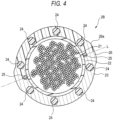
- FIG. 4 is a cross-sectional view of an optical fiber cable 2B according to a modification. The same components as those of the optical fiber cable 2 are denoted by the same reference signs, and the description thereof is omitted.
- the plurality of tensile strength members 24 are spaced apart from each other at equal intervals. Specifically, the tensile strength members 24 are provided, one by one, at positions facing each other across the center of the optical fiber cable 2B in the cross section of the optical fiber cable 2B in the radial direction.
- the same effects as those of the optical fiber cable 2 can also be attained. Further, in the optical fiber cable 2B, since the plurality of tensile strength members 24 are spaced apart from each other at equal intervals, the non-uniformity in the rigidity of the cable due to the position where the tensile strength members 24 are embedded is reduced. Therefore, it is possible to implement the optical fiber cable 2B that is less likely to be bent during the pneumatic feeding.
Landscapes
- Physics & Mathematics (AREA)
- General Physics & Mathematics (AREA)
- Optics & Photonics (AREA)
- Light Guides In General And Applications Therefor (AREA)
Abstract
Description
- The present disclosure relates to an optical fiber cable.
- The present application claims priority based on
Japanese Patent Application No. 2021-205002 filed on December 17, 2021 - In the related art, as an optical fiber cable, there is a slot type cable in which a plurality of optical fibers are accommodated in a slot rod and covered with a sheath. There is also a slotless type cable in which the slot rod is omitted and a plurality of optical fibers are mounted in a cable sheath at a high density. As the optical fiber mounted in these cables, a single-core fiber including one core and a multi-core fiber including a plurality of cores are known (for example, Patent Literature 1).
- Patent Literature 1:
JP2015-052704A - An optical fiber cable including:
- a plurality of optical fibers; and
- a sheath covering the plurality of optical fibers from an outside,
- in which each of the plurality of optical fibers is a multi-core fiber including a plurality of cores,
- in which a glass diameter of each of the plurality of optical fibers is larger than 125 µm, and
- in which a core density is 11 core/mm2 or more
-
- [
FIG. 1] FIG. 1 is a cross-sectional view of an optical fiber cable according to the present embodiment. - [
FIG. 2] FIG. 2 is a partially exploded view showing an optical fiber ribbon provided in the optical fiber cable inFIG. 1 in the longitudinal direction. - [
FIG. 3] FIG. 3 is a cross-sectional view of an optical fiber provided in the optical fiber ribbon inFIG. 2 . - [
FIG. 4] FIG. 4 is a cross-sectional view of an optical fiber cable according to a modification. - Since the slot type cable includes the slot rod, it is difficult to mount the optical fibers at a high density. In the slotless type cable, there is also a limit to increasing the density of the optical fibers with the currently commonly used optical fibers having a glass diameter of 125 µm and a core wire diameter of 250 µm.
- First, an embodiment of the present disclosure will be listed and described.
- (1) An optical fiber cable according to an aspect of the present disclosure including:
- a plurality of optical fibers; and
- a sheath covering the plurality of optical fibers from an outside,
- in which each of the plurality of optical fibers is a multi-core fiber including a plurality of cores,
- in which a glass diameter of each of the plurality of optical fibers is larger than 125 µm, and
- in which a core density is 11 core/mm2 or more.
- (2) In the above (1), bending rigidity of each of the plurality of optical fibers may be 0.25 N·mm2 or more.
Generally, In a case where an optical fiber cable is provided in a duct by the pneumatic feeding, when the bending rigidity of the optical fiber cable is low, the cable may meander. In an environment of -30°C or -40°C, the sheath contracts, and the macro bending of the optical fiber may occur within the sheath. According to the present disclosure, since the bending rigidity of each of the optical fibers is 0.25 N·mm2 or more, the bending rigidity of the optical fiber cable also becomes high, and the optical fiber cable is less likely to meander during the pneumatic feeding. The macro bending is also less likely to occur in a low temperature environment. - (3) In the above (1) or (2), a tensile strength of the optical fiber cable may be 1300 N or more.
According to the present disclosure, the tensile strength of the optical fiber cable is 1300 N or more. Therefore, it is possible to implement an optical fiber cable that can withstand general pneumatic feeding. - (4) In any one of the above (1) to (3), a glass diameter of each of the plurality of optical fibers may be 175 µm or more and 185 µm or less.
According to the present disclosure, since the glass diameters of the plurality of optical fibers are 175 µm or more and 185 µm or less, the bending rigidity of each of the optical fibers is higher than that of the optical fiber having a glass diameter of 125 µm. Therefore, the optical fiber cable is less likely to meander during the pneumatic feeding, and the macro bending is also less likely to occur in the low temperature environment. Since a wide interval between the cores can be secured, the leakage (the crosstalk) of an optical signal between the cores can be prevented. - (5) In any one of the above (1) to (4), each of the plurality of optical fibers may include 12 cores.
According to the present disclosure, since each of the optical fibers includes 12 cores, the core density can be further increased as compared with the optical fiber including a related-art number of cores. - (6) In any one of the above (1) to (5), the plurality of optical fibers may be an intermittent coupling type optical fiber ribbon in which, in a state where the plurality of optical fibers are arranged in parallel in a direction orthogonal to a longitudinal direction of the plurality of optical fibers, a coupling portion that has a state where adjacent optical fibers of some or all of the plurality of optical fibers are coupled, and a non-coupling portion that has a state where the adjacent optical fibers are not coupled are intermittently provided in the longitudinal direction.
- The intermittent coupling type optical fiber ribbon may be used as the plurality of optical fibers. By using the intermittent coupling type optical fiber ribbon, it is possible to mount the optical fibers in the optical fiber cable at a higher density.
- According to the present disclosure, it is possible to provide an optical fiber cable having a high core density.
- A specific example of an optical fiber cable according to an embodiment of the present disclosure will be described with reference to the drawings.
- It should be noted that the present disclosure is not limited to these examples, but is indicated by claims, and is intended to include all changes within the meaning and scope equivalent to the claims.
-
FIG. 1 is a cross-sectional view of anoptical fiber cable 2 according to an embodiment of the present disclosure. As shown inFIG. 1 , theoptical fiber cable 2 includes a plurality of optical fibers that are in the form of a plurality ofoptical fiber ribbons 21, awater absorption tape 22 for example, a cable sheath 23 (a sheath), at least onetensile strength member 24, at least onetear string 25, and a plurality ofprotrusions 26 for example. The cable outer diameter of theoptical fiber cable 2 is, for example, 20 mm. The tensile strength of theoptical fiber cable 2 is 1300 N or more. - The
water absorption tape 22 is longitudinally or spirally wrapped around the whole of the plurality ofoptical fiber ribbons 21, for example. Thewater absorption tape 22 is, for example, a tape subjected to water absorption processing by applying a water absorption powder to a base fabric made of polyester or the like. The thickness of thewater absorption tape 22 is, for example, 0.3 mm. In the present embodiment, theoptical fiber cable 2 includes thewater absorption tape 22. Alternatively, theoptical fiber cable 2 may not include thewater absorption tape 22. - The
cable sheath 23 covers the periphery of thewater absorption tape 22. In other words, thecable sheath 23 covers the plurality ofoptical fiber ribbons 21 from the outside. Thecable sheath 23 accommodates the plurality of optical fiber ribbons 21 (the plurality of optical fibers). A plurality of thetensile strength members 24 are embedded in the layer of thecable sheath 23. The thickness of thecable sheath 23 is, for example, 1.5 mm. Thecable sheath 23 is made of, for example, a flame-retardant material. Examples of the flame-retardant material include a vinyl resin such as polyvinyl chloride (PVC) containing a flame-retardant inorganic material such as magnesium hydroxide or aluminum hydroxide, and a polyolefin resin such as polyethylene (PE). Thecable sheath 23 may contain a release agent. Examples of the release agent include silicon-based release agents such as silicon and siloxane. - The
tensile strength members 24 are arranged in the longitudinal direction of theoptical fiber cable 2 along the plurality ofoptical fiber ribbons 21. The diameter of thetensile strength member 24 is, for example, 0.5 mm. Thetensile strength member 24 is made of fiber reinforced plastic (FRP) such as aramid FRP, glass FRP, or carbon FRP. Thetensile strength member 24 may be made of a liquid crystal polymer. Thetensile strength member 24 is preferably non-inductive. The fiber-reinforced plastic (FRP) is generally a combustible material. From the viewpoint of improving the flame retardance of the entireoptical fiber cable 2, thetensile strength member 24 is preferably provided not near the surface layer of thecable sheath 23 but near the center of theoptical fiber cable 2, inside thecable sheath 23. - The
tensile strength member 24 has a circular cross section in the radial direction. In the present embodiment, eighttensile strength members 24 are embedded in the layer of thecable sheath 23. The eighttensile strength members 24 form pairs of two tensile strength members. In the following description, the paired twotensile strength members 24 are collectively referred to as a tensile strength member set 240. - In the present embodiment, the four tensile strength member sets 240 are separated from each other and embedded in the layer of the
cable sheath 23. In theoptical fiber cable 2, the four tensile strength member sets 240 are spaced apart from each other at equal intervals. Specifically, the tensile strength member sets 240 are provided, one by one, at positions facing each other across the center of theoptical fiber cable 2, in the cross section of theoptical fiber cable 2 in the radial direction. In the cross section of theoptical fiber cable 2 in the radial direction, the tensile strength member sets 240 are provided such that a straight line connecting two tensile strength member sets 240 facing each other and another straight line connecting the other two tensile strength member sets 240 facing each other are orthogonal to each other. - The tear strings 25 are provided to tear the
cable sheath 23. The tear strings 25 are arranged along the plurality ofoptical fiber ribbons 21 in the longitudinal direction of theoptical fiber cable 2, in the layer of thecable sheath 23. In the present embodiment, twotear strings 25 are provided. Each of the tear strings 25 is located substantially in the middle of the adjacent tensile strength member sets 240. The twotear strings 25 face each other. The four tensile strength member sets 240 are arranged line-symmetrically with respect to a straight line L connecting centers of the tear strings 25 and theoptical fiber cable 2, in the cable cross-sectional view. The operator can tear thecable sheath 23 in the longitudinal direction by pulling out thetear string 25 and take out theoptical fiber ribbon 21. Thetear string 25 has a fiber shape, and is made of, for example, a plastic material (for example, polyester) resistant to tension. - A plurality of (two in the present embodiment)
protrusions 26 are provided. The twoprotrusions 26 are provided along the longitudinal direction of theoptical fiber cable 2. Theprotrusions 26 may be provided continuously along the longitudinal direction, or may be provided intermittently. Further, the twoprotrusions 26 are provided to, for example, facing each other across the center of theoptical fiber cable 2 in the circumferential direction of the outer peripheral portion of thecable sheath 23, in the cross section of theoptical fiber cable 2 in the radial direction. In the present embodiment, theprotrusion 26 is provided on the straight line L connecting the centers of the tear strings 25 and theoptical fiber cable 2. Theprotrusion 26 is formed on the outer peripheral portion of thecable sheath 23 in the state of protruding in the radial direction of theoptical fiber cable 2. Theprotrusion 26 has acurved surface 26a in a protruding direction thereof. Theprotrusion 26 is formed integrally with thecable sheath 23 by extrusion molding. In the present embodiment, theoptical fiber cable 2 includes the twoprotrusions 26. Alternatively, theoptical fiber cable 2 may not include theprotrusion 26. - Next, the
optical fiber ribbon 21 will be described in detail with reference toFIG. 2. FIG. 2 is a partially exploded view showing theoptical fiber ribbon 21 in the longitudinal direction. As shown inFIG. 2 , theoptical fiber ribbon 21 is an intermittent coupling type optical fiber ribbon. In theoptical fiber ribbon 21, in the state where a plurality ofoptical fibers 211A to 211L are arranged in parallel in a direction orthogonal to the longitudinal direction of the plurality ofoptical fibers 211A to 211L, acoupling portion 212 in which adjacent optical fibers of some or all of the plurality ofoptical fibers 211A to 211L are coupled, and anon-coupling portion 213 in which the adjacent optical fibers are not coupled are intermittently provided in the longitudinal direction. The bending rigidity of each of theoptical fibers 211A to 211L is 0.25 N·mm2 or more. - In the
optical fiber ribbon 21 according to the present embodiment, the 12optical fibers 211A to 211L are arranged in parallel. The portion where thecoupling portion 212 and thenon-coupling portion 213 are intermittently provided may be between a part of the optical fibers (intermittently every two cores), or may be between all the optical fibers (intermittently every one core). Theoptical fiber ribbon 21 shown inFIG. 2 is intermittent every two cores, and thenon-coupling portion 213 is not provided between theoptical fibers - The
coupling portion 212 in theoptical fiber ribbon 21 is formed by applying acoupling resin 214 made of, for example, an ultraviolet curable resin or a thermosetting resin between the optical fibers. By applying thecoupling resin 214 between predetermined optical fibers, thecoupling portion 212 and thenon-coupling portion 213 are intermittently provided, and theoptical fibers 211A to 211L are integrated in parallel. Thecoupling resin 214 may be applied only to one surface of parallel surfaces formed by the paralleloptical fibers 211A to 211L, or may be applied to both surfaces. Theoptical fiber ribbon 21 may be manufactured such that, for example, a tape resin is applied to one surface or both surfaces of theoptical fibers 211A to 211L, which are arranged in parallel, to couple all theoptical fibers 211A to 211L to each other, and then a part of theoptical fibers 211A to 211L is cleaved by a rotary blade or the like to form thenon-coupling portion 213. - Next, the
optical fiber 211A will be described with reference toFIG. 3 . The configurations of theoptical fibers 211B to 211L other than theoptical fiber 211A are the same as that of theoptical fiber 211A.FIG. 3 is a cross-sectional view of theoptical fiber 211A. As shown inFIG. 3 , theoptical fiber 211A includes 12cores 215, acladding portion 216, and twocoating layers optical fiber 211A is a multi-core fiber including a plurality ofcores 215. An outer diameter R1 of theoptical fiber 211A is, for example, 250 µm ± 15 µm. - The
core 215 is circular, in the cross section in the radial direction. Thecore 215 is made of quartz glass and contains an additive to increase the refractive index. The refractive index of thecore 215 is higher than the refractive index of thecladding portion 216. The outer diameter of thecore 215 is, for example, 5 µm or more and 10 µm or less. - The
cladding portion 216 integrally surrounds the 12cores 215. Thecladding portion 216 is made of silica glass, for example pure silica glass. Thecladding portion 216 is circular, in the cross section in the radial direction. An outer diameter (a glass diameter) R2 of thecladding portion 216 is, for example, 175 µm or more and 185 µm or less, and is larger than the glass diameter of a general optical fiber. - Both of the two
coating layers cladding portion 216. The total coating thickness of the coating layers 217 and 218 is, for example, 37.5 µm. Theinner coating layer 217 of the two coating layers is made of a cured product of a primary resin. Theouter coating layer 218 of the two coating layers is made of a cured product of a secondary resin. - In the primary resin of the
inner coating layer 217 that is in contact with thecladding portion 216, a soft resin with a relatively low Young's modulus is used as a buffer layer. In the secondary resin of theouter coating layer 218 that is in contact with theinner coating layer 217, a hard resin with a relatively high Young's modulus is used as a protective layer. The Young's modulus of the cured product of the secondary resin is, at the room temperature (for example, 23°C), 900 MPa or more, preferably 1000 MPa or more, and more preferably 1500 MPa or more. - The secondary resin of the
outer coating layer 218 is preferably a resin composition containing a base resin containing a urethane acrylate oligomer or urethane methacrylate oligomer, a monomer having a phenoxy group, a photopolymerization initiator and a silane coupling agent, and containing hydrophobic inorganic oxide particles. The content of inorganic oxide particles in the resin composition is 1% by mass or more and 45% by mass or less based on the total amount of the resin composition. - Each of the
optical fibers 211A to 211L includes, for example, the 12cores 215, and in theoptical fiber cable 2, for example, 24 such 12-core intermittently coupledoptical fiber ribbons 21 are arranged. Therefore, theoptical fiber cable 2 according to the present embodiment has a total of 3456cores 215. The outer diameter of theoptical fiber cable 2 according to the present embodiment is, for example, 20 mm, and the core density, which is the density of cores in the entire cross section of theoptical fiber cable 2, is 11 core/mm2 or more. - The core density is a value obtained by dividing the total number of the
cores 215 of the plurality of optical fibers accommodated in theoptical fiber cable 2 by the cable cross-sectional area (the cross-sectional area obtained based on the outer diameter of the optical fiber cable 2). - Next, the bending rigidity of the
optical fiber 211A will be described. The bending rigidity of theoptical fibers 211B to 211L other than theoptical fiber 211A is the same as the bending rigidity of theoptical fiber 211A. - In the material mechanics, the bending rigidity of a general round bar is obtained according to the following Formula 1. In Formula 1, EI is the bending rigidity (N·mm2), E is the Young's modulus (N/mm2), and d is the radius (mm) of the round bar.

- Here, the
optical fiber 211A is regarded as a composite of a glass portion including thecore 215 and thecladding portion 216, the primary resin of theinner coating layer 217, and the secondary resin of theouter coating layer 218. The bending rigidity of theoptical fiber 211A serving as the composite is obtained by the followingFormula 2. In the following formula, EITOTAL is the bending rigidity (N·mm2) of theoptical fiber 211A, E1 is the Young's modulus (N/mm2) of the glass portion, E2 is the Young's modulus (N/mm2) of the primary resin, and E3 is the Young's modulus (N/mm2) of the secondary resin. D1 is the radius (mm) of the glass portion, D2 is the radius (mm) of the glass portion covered with the primary resin, and D3 is the radius (mm) of the glass portion covered with the primary resin and the secondary resin.
- The bending rigidity of the
optical fiber 211A is obtained using theabove Formula 2. In the present embodiment, the Young's modulus E1 of the glass diameter is 80100 N/mm2, the Young's modulus E2 of the primary resin is 0.5 N/mm2, and the Young's modulus E3 of the secondary resin is 1000 N/mm2. The radius D1 of the glass portion is 0.09 mm, the radius D2 of the glass portion covered with the primary resin is 0.11 mm, and the radius D3 of the glass portion covered with the primary resin and the secondary resin is 0.125 mm. At this time, the bending rigidity EITOTAL of theoptical fiber 211A is 0.258 N·mm2. That is, the bending rigidity of theoptical fiber 211A is 0.25 N·mm2 or more. - As a comparative example, the bending rigidity of the optical fiber having a glass diameter of 125 µm is obtained. The Young's modulus E1 of the glass diameter is 80100 N/mm2, the Young's modulus E2 of the primary resin is 0.5 N/mm2, and the Young's modulus E3 of the secondary resin is 1000 N/mm2. The radius D1 of the glass portion is 0.0625 mm, the radius D2 of the glass portion covered with the primary resin is 0.11 mm, and the radius D3 of the glass portion covered with the primary resin and the secondary resin is 0.125 mm. At this time, the bending rigidity of the optical fiber according to the comparative example is 0.060 N·mm2. The bending rigidity of the
optical fiber 211A according to the present embodiment is 4.3 times the bending rigidity of the optical fiber having a glass diameter of 125 µm, which is relatively high. - Next, the tensile strength of the
optical fiber cable 2 will be described. In the present embodiment, the tensile strength of theoptical fiber cable 2 is the sum of the allowable tension of the plurality ofoptical fibers 211A to 211L and the allowable tension of the plurality oftensile strength members 24. The allowable tension (N) is obtained according to cross-sectional area (mm2) × Young's modulus (N/mm2) × elongation strain (%). - The radius D1 of the glass portion of the
optical fiber 211A is 0.09 mm, and the Young's modulus is 47040 N/mm2. When theoptical fiber 211A is elongated by 0.3%, the allowable tension of theoptical fiber 211A is 3.59 N. When theoptical fiber cable 2 includes 288 optical fibers, the allowable tension of the plurality of optical fibers is 1034 N. - When the radius of one
tensile strength member 24 is 0.25 mm, the Young's modulus is 61740 N/mm2, and thetensile strength member 24 is elongated by 0.3%, the allowable tension of thetensile strength member 24 is 36.3 N. Since theoptical fiber cable 2 according to the present embodiment includes eighttensile strength members 24, the allowable tension of the plurality oftensile strength members 24 is 291 N. Accordingly, the tensile strength of theoptical fiber cable 2 is 1325 N. That is, the tensile strength of theoptical fiber cable 2 is 1300 N or more. - As a comparative example, the allowable tension of an optical fiber cable including 288 optical fibers, each having a glass diameter of 125 µm, and 16 tensile strength members is obtained. In this case, the allowable tension of the plurality of optical fibers is 498 N, and the allowable tension of the plurality of tensile strength members is 582 N. Accordingly, the allowable tension of the optical fiber cable according to the comparative example is 1080 N.
- In this way, the tensile strength of the
optical fiber cable 2 according to the present embodiment is 1300 N or more, and is the same allowable tension as that of the optical fiber cable according to the comparative example. That is, even when the glass diameter is increased from 125 µm to 180 µm and the number of thetensile strength members 24 is reduced from 16 to 8, the same allowable tension as that of the optical fiber cable in the related art is achieved. - As described above, in the
optical fiber cable 2 according to the present embodiment, the glass diameters of theoptical fibers 211A to 211L are larger than 125 µm. Therefore, the number of cores per optical fiber can be increased, and theoptical fiber cable 2 having a core density of 11 core/mm2 or more can be achieved. - In the present embodiment, the eight
tensile strength members 24 form pairs, each pair including two. However, the arrangement of thetensile strength members 24 is not limited thereto. The eighttensile strength members 24 may be provided one by one.FIG. 4 is a cross-sectional view of anoptical fiber cable 2B according to a modification. The same components as those of theoptical fiber cable 2 are denoted by the same reference signs, and the description thereof is omitted. - As shown in
FIG. 4 , the plurality oftensile strength members 24 are spaced apart from each other at equal intervals. Specifically, thetensile strength members 24 are provided, one by one, at positions facing each other across the center of theoptical fiber cable 2B in the cross section of theoptical fiber cable 2B in the radial direction. - In the
optical fiber cable 2B according to the modification, the same effects as those of theoptical fiber cable 2 can also be attained. Further, in theoptical fiber cable 2B, since the plurality oftensile strength members 24 are spaced apart from each other at equal intervals, the non-uniformity in the rigidity of the cable due to the position where thetensile strength members 24 are embedded is reduced. Therefore, it is possible to implement theoptical fiber cable 2B that is less likely to be bent during the pneumatic feeding. - Although the present disclosure has been described in detail with reference to the specific embodiment, it is apparent to those skilled in the art that various changes and modifications can be made without departing from the spirit and scope of the present disclosure. In addition, the number, positions, shapes, and the like of the constituent members described above are not limited to those in the above embodiment, and can be changed to the numbers, positions, shapes, and the like suitable for carrying out the present disclosure.
-
- 2, 2B: optical fiber cable
- 21: optical fiber ribbon
- 22: water absorption tape
- 23: cable sheath
- 24: tensile strength member
- 25: tear string
- 26: protrusion
- 26a: surface
- 211A, 211B, 211C, 211D, 211E, 211F, 211G, 211H, 211I, 211J, 211K, 211L: optical fiber
- 212: coupling portion
- 213: non-coupling portion
- 214: coupling resin
- 215: core
- 216: cladding portion
- 217: inner coating layer
- 218: outer coating layer
- 240: tensile strength member set
- L: straight line
- R1: outer diameter of optical fiber
- R2: outer diameter (glass diameter) of cladding portion
Claims (6)
- An optical fiber cable comprising:a plurality of optical fibers; anda sheath covering the plurality of optical fibers from an outside,wherein each of the plurality of optical fibers is a multi-core fiber including a plurality of cores,wherein a glass diameter of each of the plurality of optical fibers is larger than 125 µm, andwherein a core density is 11 core/mm2 or more.
- The optical fiber cable according to claim 1,
wherein bending rigidity of each of the plurality of optical fibers is 0.25 N·mm2 or more. - The optical fiber cable according to claim 1 or 2,
wherein a tensile strength of the optical fiber cable is 1300 N or more. - The optical fiber cable according to any one of claims 1 to 3,
wherein a glass diameter of each of the plurality of optical fibers is 175 µm or more and 185 µm or less. - The optical fiber cable according to any one of claims 1 to 4,
wherein each of the plurality of optical fibers includes 12 cores. - The optical fiber cable according to any one of claims 1 to 5,
wherein the plurality of optical fibers are an intermittent coupling type optical fiber ribbon in which, in a state where the plurality of optical fibers are arranged in parallel in a direction orthogonal to a longitudinal direction of the plurality of optical fibers, a coupling portion that has a state where adjacent optical fibers of some or all of the plurality of optical fibers are coupled, and a non-coupling portion that has a state where the adjacent optical fibers are not coupled are intermittently provided in the longitudinal direction.
Applications Claiming Priority (2)
| Application Number | Priority Date | Filing Date | Title |
|---|---|---|---|
| JP2021205002 | 2021-12-17 | ||
| PCT/JP2022/046393 WO2023113012A1 (en) | 2021-12-17 | 2022-12-16 | Optical fiber cable |
Publications (2)
| Publication Number | Publication Date |
|---|---|
| EP4451028A1 true EP4451028A1 (en) | 2024-10-23 |
| EP4451028A4 EP4451028A4 (en) | 2025-03-26 |
Family
ID=86774443
Family Applications (1)
| Application Number | Title | Priority Date | Filing Date |
|---|---|---|---|
| EP22907534.6A Pending EP4451028A4 (en) | 2021-12-17 | 2022-12-16 | FIBER OPTIC CABLE |
Country Status (3)
| Country | Link |
|---|---|
| EP (1) | EP4451028A4 (en) |
| JP (1) | JPWO2023113012A1 (en) |
| WO (1) | WO2023113012A1 (en) |
Families Citing this family (1)
| Publication number | Priority date | Publication date | Assignee | Title |
|---|---|---|---|---|
| WO2025263437A1 (en) * | 2024-06-17 | 2025-12-26 | 住友電気工業株式会社 | Optical fiber ribbon and method for manufacturing optical fiber ribbon |
Family Cites Families (12)
| Publication number | Priority date | Publication date | Assignee | Title |
|---|---|---|---|---|
| WO2010001663A1 (en) * | 2008-06-30 | 2010-01-07 | 日本電信電話株式会社 | Optical fiber cable and optical fiber tape |
| US8805143B2 (en) * | 2009-10-19 | 2014-08-12 | Draka Comteq, B.V. | Optical-fiber cable having high fiber count and high fiber density |
| JP2015052704A (en) | 2013-09-06 | 2015-03-19 | 住友電気工業株式会社 | Optical fiber tape core, optical cable, optical fiber cord, and tape core connection method |
| JP6841837B2 (en) * | 2016-09-30 | 2021-03-10 | 株式会社フジクラ | Optical fiber ribbon manufacturing method and optical fiber cable manufacturing method |
| WO2019142841A1 (en) * | 2018-01-18 | 2019-07-25 | 住友電気工業株式会社 | Optical fiber cable |
| CN112867952B (en) * | 2018-11-06 | 2023-01-06 | 住友电气工业株式会社 | fiber optic cable |
| JP6715372B1 (en) * | 2019-04-25 | 2020-07-01 | 日本電信電話株式会社 | Multi-core optical fiber and design method |
| WO2020256019A1 (en) * | 2019-06-19 | 2020-12-24 | 住友電気工業株式会社 | Optical fiber cable |
| JP7326933B2 (en) * | 2019-07-03 | 2023-08-16 | 住友電気工業株式会社 | multicore optical fiber |
| WO2021201107A1 (en) * | 2020-03-31 | 2021-10-07 | 住友電気工業株式会社 | Optical fiber cable |
| EP4279965A4 (en) * | 2021-01-12 | 2024-06-05 | Sumitomo Electric Industries, Ltd. | FIBER OPTICAL CABLE AND CONNECTOR EQUIPPED CABLE |
| WO2022256287A1 (en) * | 2021-06-02 | 2022-12-08 | Corning Research & Development Corporation | High core density optical fiber cables |
-
2022
- 2022-12-16 JP JP2023567842A patent/JPWO2023113012A1/ja active Pending
- 2022-12-16 WO PCT/JP2022/046393 patent/WO2023113012A1/en not_active Ceased
- 2022-12-16 EP EP22907534.6A patent/EP4451028A4/en active Pending
Also Published As
| Publication number | Publication date |
|---|---|
| JPWO2023113012A1 (en) | 2023-06-22 |
| EP4451028A4 (en) | 2025-03-26 |
| WO2023113012A1 (en) | 2023-06-22 |
Similar Documents
| Publication | Publication Date | Title |
|---|---|---|
| US11762161B2 (en) | Optical fiber cable | |
| JP7156181B2 (en) | fiber optic cable | |
| EP3879323B1 (en) | Optical fiber cable | |
| EP1531352B1 (en) | Optical fiber cables | |
| AU2008244628B2 (en) | Tubeless fiber optic cable having torque balanced strength members | |
| EP4279965A1 (en) | Optical fiber cable and connector-equipped cable | |
| CN113056690B (en) | Fiber optic cable with spoolable ribbon and central strength member | |
| CN100399090C (en) | Fiber optic ribbon with preferential pull section | |
| EP3923052A1 (en) | Intermittent connection-type optical fiber tape core wire, optical fiber cable, and method for manufacturing intermittent connection-type optical fiber tape core wire | |
| EP4535056A1 (en) | Optical fiber ribbon | |
| JP2004206048A (en) | Optical fiber ribbon and manufacturing method thereof | |
| EP4451028A1 (en) | Optical fiber cable | |
| JP7156178B2 (en) | fiber optic cable | |
| EP4455751A1 (en) | Optical cable and method for manufacturing optical cable | |
| US20130188915A1 (en) | Plastic optical fiber unit and plastic optical fiber cable using same | |
| US20230305251A1 (en) | Optical fiber cable and cable with connector | |
| KR102770549B1 (en) | Optical Cable | |
| US20240319466A1 (en) | Optical fiber cable | |
| EP4350408B1 (en) | FIBER OPTIC CABLE AND FIBER OPTIC CABLE MANUFACTURING DEVICE | |
| WO2025057409A1 (en) | Optical fiber cable | |
| WO2025135055A1 (en) | Optical fiber cable | |
| EP4465102A1 (en) | Optical fiber cable | |
| US20210048590A1 (en) | Arrangement of optical fibre ribbon stack and an optical fibre ribbon thereof | |
| WO2023120483A1 (en) | Optical fiber cable | |
| JP2025180970A (en) | fiber optic cable |
Legal Events
| Date | Code | Title | Description |
|---|---|---|---|
| STAA | Information on the status of an ep patent application or granted ep patent |
Free format text: STATUS: THE INTERNATIONAL PUBLICATION HAS BEEN MADE |
|
| PUAI | Public reference made under article 153(3) epc to a published international application that has entered the european phase |
Free format text: ORIGINAL CODE: 0009012 |
|
| STAA | Information on the status of an ep patent application or granted ep patent |
Free format text: STATUS: REQUEST FOR EXAMINATION WAS MADE |
|
| 17P | Request for examination filed |
Effective date: 20240502 |
|
| AK | Designated contracting states |
Kind code of ref document: A1 Designated state(s): AL AT BE BG CH CY CZ DE DK EE ES FI FR GB GR HR HU IE IS IT LI LT LU LV MC ME MK MT NL NO PL PT RO RS SE SI SK SM TR |
|
| A4 | Supplementary search report drawn up and despatched |
Effective date: 20250225 |
|
| DAV | Request for validation of the european patent (deleted) | ||
| DAX | Request for extension of the european patent (deleted) | ||
| RIC1 | Information provided on ipc code assigned before grant |
Ipc: G02B 6/02 20060101ALI20250219BHEP Ipc: G02B 6/44 20060101AFI20250219BHEP |