EP4450883A1 - Ventilation system - Google Patents
Ventilation system Download PDFInfo
- Publication number
- EP4450883A1 EP4450883A1 EP22907063.6A EP22907063A EP4450883A1 EP 4450883 A1 EP4450883 A1 EP 4450883A1 EP 22907063 A EP22907063 A EP 22907063A EP 4450883 A1 EP4450883 A1 EP 4450883A1
- Authority
- EP
- European Patent Office
- Prior art keywords
- fan
- supply
- exhaust fan
- ventilation system
- control unit
- Prior art date
- Legal status (The legal status is an assumption and is not a legal conclusion. Google has not performed a legal analysis and makes no representation as to the accuracy of the status listed.)
- Granted
Links
Images




Classifications
-
- F—MECHANICAL ENGINEERING; LIGHTING; HEATING; WEAPONS; BLASTING
- F24—HEATING; RANGES; VENTILATING
- F24F—AIR-CONDITIONING; AIR-HUMIDIFICATION; VENTILATION; USE OF AIR CURRENTS FOR SCREENING
- F24F11/00—Control or safety arrangements
- F24F11/0001—Control or safety arrangements for ventilation
-
- F—MECHANICAL ENGINEERING; LIGHTING; HEATING; WEAPONS; BLASTING
- F24—HEATING; RANGES; VENTILATING
- F24F—AIR-CONDITIONING; AIR-HUMIDIFICATION; VENTILATION; USE OF AIR CURRENTS FOR SCREENING
- F24F12/00—Use of energy recovery systems in air conditioning, ventilation or screening
- F24F12/001—Use of energy recovery systems in air conditioning, ventilation or screening with heat-exchange between supplied and exhausted air
- F24F12/002—Use of energy recovery systems in air conditioning, ventilation or screening with heat-exchange between supplied and exhausted air using an intermediate heat-transfer fluid
- F24F12/003—Use of energy recovery systems in air conditioning, ventilation or screening with heat-exchange between supplied and exhausted air using an intermediate heat-transfer fluid using a heat pump
-
- F—MECHANICAL ENGINEERING; LIGHTING; HEATING; WEAPONS; BLASTING
- F04—POSITIVE - DISPLACEMENT MACHINES FOR LIQUIDS; PUMPS FOR LIQUIDS OR ELASTIC FLUIDS
- F04D—NON-POSITIVE-DISPLACEMENT PUMPS
- F04D19/00—Axial-flow pumps
- F04D19/002—Axial flow fans
-
- F—MECHANICAL ENGINEERING; LIGHTING; HEATING; WEAPONS; BLASTING
- F04—POSITIVE - DISPLACEMENT MACHINES FOR LIQUIDS; PUMPS FOR LIQUIDS OR ELASTIC FLUIDS
- F04D—NON-POSITIVE-DISPLACEMENT PUMPS
- F04D25/00—Pumping installations or systems
- F04D25/16—Combinations of two or more pumps ; Producing two or more separate gas flows
- F04D25/166—Combinations of two or more pumps ; Producing two or more separate gas flows using fans
-
- F—MECHANICAL ENGINEERING; LIGHTING; HEATING; WEAPONS; BLASTING
- F04—POSITIVE - DISPLACEMENT MACHINES FOR LIQUIDS; PUMPS FOR LIQUIDS OR ELASTIC FLUIDS
- F04D—NON-POSITIVE-DISPLACEMENT PUMPS
- F04D27/00—Control, e.g. regulation, of pumps, pumping installations or pumping systems specially adapted for elastic fluids
- F04D27/001—Testing thereof; Determination or simulation of flow characteristics; Stall or surge detection, e.g. condition monitoring
-
- F—MECHANICAL ENGINEERING; LIGHTING; HEATING; WEAPONS; BLASTING
- F04—POSITIVE - DISPLACEMENT MACHINES FOR LIQUIDS; PUMPS FOR LIQUIDS OR ELASTIC FLUIDS
- F04D—NON-POSITIVE-DISPLACEMENT PUMPS
- F04D27/00—Control, e.g. regulation, of pumps, pumping installations or pumping systems specially adapted for elastic fluids
- F04D27/004—Control, e.g. regulation, of pumps, pumping installations or pumping systems specially adapted for elastic fluids by varying driving speed
-
- F—MECHANICAL ENGINEERING; LIGHTING; HEATING; WEAPONS; BLASTING
- F04—POSITIVE - DISPLACEMENT MACHINES FOR LIQUIDS; PUMPS FOR LIQUIDS OR ELASTIC FLUIDS
- F04D—NON-POSITIVE-DISPLACEMENT PUMPS
- F04D27/00—Control, e.g. regulation, of pumps, pumping installations or pumping systems specially adapted for elastic fluids
- F04D27/008—Stop safety or alarm devices, e.g. stop-and-go control; Disposition of check-valves
-
- F—MECHANICAL ENGINEERING; LIGHTING; HEATING; WEAPONS; BLASTING
- F04—POSITIVE - DISPLACEMENT MACHINES FOR LIQUIDS; PUMPS FOR LIQUIDS OR ELASTIC FLUIDS
- F04D—NON-POSITIVE-DISPLACEMENT PUMPS
- F04D27/00—Control, e.g. regulation, of pumps, pumping installations or pumping systems specially adapted for elastic fluids
- F04D27/02—Surge control
- F04D27/0292—Stop safety or alarm devices, e.g. stop-and-go control; Disposition of check-valves
-
- F—MECHANICAL ENGINEERING; LIGHTING; HEATING; WEAPONS; BLASTING
- F24—HEATING; RANGES; VENTILATING
- F24F—AIR-CONDITIONING; AIR-HUMIDIFICATION; VENTILATION; USE OF AIR CURRENTS FOR SCREENING
- F24F11/00—Control or safety arrangements
- F24F11/30—Control or safety arrangements for purposes related to the operation of the system, e.g. for safety or monitoring
- F24F11/32—Responding to malfunctions or emergencies
-
- F—MECHANICAL ENGINEERING; LIGHTING; HEATING; WEAPONS; BLASTING
- F24—HEATING; RANGES; VENTILATING
- F24F—AIR-CONDITIONING; AIR-HUMIDIFICATION; VENTILATION; USE OF AIR CURRENTS FOR SCREENING
- F24F11/00—Control or safety arrangements
- F24F11/30—Control or safety arrangements for purposes related to the operation of the system, e.g. for safety or monitoring
- F24F11/32—Responding to malfunctions or emergencies
- F24F11/38—Failure diagnosis
-
- F—MECHANICAL ENGINEERING; LIGHTING; HEATING; WEAPONS; BLASTING
- F24—HEATING; RANGES; VENTILATING
- F24F—AIR-CONDITIONING; AIR-HUMIDIFICATION; VENTILATION; USE OF AIR CURRENTS FOR SCREENING
- F24F11/00—Control or safety arrangements
- F24F11/70—Control systems characterised by their outputs; Constructional details thereof
- F24F11/80—Control systems characterised by their outputs; Constructional details thereof for controlling the temperature of the supplied air
- F24F11/86—Control systems characterised by their outputs; Constructional details thereof for controlling the temperature of the supplied air by controlling compressors within refrigeration or heat pump circuits
-
- F—MECHANICAL ENGINEERING; LIGHTING; HEATING; WEAPONS; BLASTING
- F24—HEATING; RANGES; VENTILATING
- F24F—AIR-CONDITIONING; AIR-HUMIDIFICATION; VENTILATION; USE OF AIR CURRENTS FOR SCREENING
- F24F7/00—Ventilation
-
- F—MECHANICAL ENGINEERING; LIGHTING; HEATING; WEAPONS; BLASTING
- F05—INDEXING SCHEMES RELATING TO ENGINES OR PUMPS IN VARIOUS SUBCLASSES OF CLASSES F01-F04
- F05D—INDEXING SCHEME FOR ASPECTS RELATING TO NON-POSITIVE-DISPLACEMENT MACHINES OR ENGINES, GAS-TURBINES OR JET-PROPULSION PLANTS
- F05D2260/00—Function
- F05D2260/85—Starting
-
- F—MECHANICAL ENGINEERING; LIGHTING; HEATING; WEAPONS; BLASTING
- F05—INDEXING SCHEMES RELATING TO ENGINES OR PUMPS IN VARIOUS SUBCLASSES OF CLASSES F01-F04
- F05D—INDEXING SCHEME FOR ASPECTS RELATING TO NON-POSITIVE-DISPLACEMENT MACHINES OR ENGINES, GAS-TURBINES OR JET-PROPULSION PLANTS
- F05D2270/00—Control
- F05D2270/30—Control parameters, e.g. input parameters
- F05D2270/301—Pressure
-
- F—MECHANICAL ENGINEERING; LIGHTING; HEATING; WEAPONS; BLASTING
- F05—INDEXING SCHEMES RELATING TO ENGINES OR PUMPS IN VARIOUS SUBCLASSES OF CLASSES F01-F04
- F05D—INDEXING SCHEME FOR ASPECTS RELATING TO NON-POSITIVE-DISPLACEMENT MACHINES OR ENGINES, GAS-TURBINES OR JET-PROPULSION PLANTS
- F05D2270/00—Control
- F05D2270/30—Control parameters, e.g. input parameters
- F05D2270/303—Temperature
-
- Y—GENERAL TAGGING OF NEW TECHNOLOGICAL DEVELOPMENTS; GENERAL TAGGING OF CROSS-SECTIONAL TECHNOLOGIES SPANNING OVER SEVERAL SECTIONS OF THE IPC; TECHNICAL SUBJECTS COVERED BY FORMER USPC CROSS-REFERENCE ART COLLECTIONS [XRACs] AND DIGESTS
- Y02—TECHNOLOGIES OR APPLICATIONS FOR MITIGATION OR ADAPTATION AGAINST CLIMATE CHANGE
- Y02B—CLIMATE CHANGE MITIGATION TECHNOLOGIES RELATED TO BUILDINGS, e.g. HOUSING, HOUSE APPLIANCES OR RELATED END-USER APPLICATIONS
- Y02B30/00—Energy efficient heating, ventilation or air conditioning [HVAC]
- Y02B30/70—Efficient control or regulation technologies, e.g. for control of refrigerant flow, motor or heating
Definitions
- the present disclosure relates to a ventilation system.
- an air conditioning system including a refrigerant circuit in which a refrigerant flows and a heat source-side unit including a compressor, a plurality of utilization-side units that air-conditions an indoor space, a supply unit including a supply fan and a first heat exchanger, and an exhaust unit including an exhaust fan and a second heat exchanger are connected by a refrigerant pipe (see, for example, PATENT LITERATURE 1).
- the air conditioning system can ventilate the indoor space by the supply fan and the exhaust fan.
- PATENT LITERATURE 1 Japanese Laid-Open Patent Publication No. H3-20573
- the air conditioning system in a system including a refrigerant circuit that can be used by switching one of a first heat exchanger or a second heat exchanger as an evaporator and the other as a condenser, when any one of a supply fan or an exhaust fan cannot produce a predetermined air volume, the entire system is conventionally stopped in order to protect the refrigerant circuit. Therefore, in the system, when an abnormality occurs in any one of the supply fan or the exhaust fan, ventilation of the indoor space cannot be continued.
- An object of the present disclosure is to enable continuous ventilation of a ventilation system including a refrigerant circuit, a supply fan, and an exhaust fan.
- the ventilation system of the present disclosure including the refrigerant circuit, the supply fan, and the exhaust fan can continue ventilation of the indoor space when an abnormality occurs in the supply fan or the exhaust fan.
- control unit preferably acquires a state value of the refrigerant circuit, and when determining that the state value exceeds an allowable range, the control unit preferably stops the compressor.
- the control unit when determining that the supply fan or the exhaust fan is abnormal, the control unit preferably stops the compressor.
- the ventilation of the indoor space can be reliably continued when an abnormality occurs in the supply fan or the exhaust fan.
- the ventilation system of the present disclosure preferably further includes a notification unit that notifies an abnormality of the supply fan or the exhaust fan, in which when determining that the supply fan or the exhaust fan is abnormal, the control unit activates the notification unit.
- the notification unit can notify to a user or the like occurrence of the abnormality in the supply fan or the exhaust fan.
- control unit preferably determines whether the supply fan is normal on the basis of a correlation between the number of fan rotations and the operation current value of the supply fan, and determines whether the exhaust fan is normal on the basis of a correlation between the number of fan rotations and the operation current value of the exhaust fan.
- control unit can determine whether the supply fan or the exhaust fan is abnormal without a sensor provided separately.
- control unit when determining that one of the supply fan or the exhaust fan is abnormal, the control unit preferably increases the number of fan rotations of another one of the supply fan or the exhaust fan determined to be normal.
- the supply fan preferably includes a first supply fan and a second supply fan
- the exhaust fan preferably includes a first exhaust fan and a second exhaust fan
- the control unit preferably determines whether the first supply fan, the second supply fan, the first exhaust fan, and the second exhaust fan are normal, and when determining that any one of the supply fan or the exhaust fan is abnormal, the control unit preferably continues an operation of a remaining one of the supply fan or the exhaust fan determined to be normal.
- the ventilation system including the refrigerant circuit and a plurality of supply fans and exhaust fans can continue the ventilation of the indoor space when an abnormality occurs in the supply fans or the exhaust fans.
- the control unit when determining that any one of the first supply fan, the second supply fan, the first exhaust fan, or the second exhaust fan is abnormal, the control unit preferably increases the number of fan rotations of the supply fan or the exhaust fan determined to be normal.
- control unit preferably predicts an abnormality of the supply fan on the basis of operation data of the supply fan and predicts an abnormality of the exhaust fan on the basis of operation data of the exhaust fan.
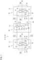
- FIG. 1 is a schematic configuration diagram of a ventilation system of the present disclosure.
- FIG. 2 is a control block diagram of the ventilation system of the present disclosure.
- a ventilation system 10 according to a first embodiment is referred to as a first ventilation system 11
- a ventilation system 10 according to a second embodiment is referred to as a second ventilation system 12.
- the configuration common to the first ventilation system 11 and the second ventilation system 12 will be described.
- the ventilation system 10 of the present disclosure illustrated in FIG. 1 is installed on a building such as an office building or a factory, and achieves ventilation of a target space in the building.
- the ventilation system 10 includes a supply unit 20, an exhaust unit 30, a compressor unit 40, and a refrigerant circuit 50.
- the supply unit 20 includes a first casing 21, a supply fan 22, and a first heat exchanger 23.
- the first casing 21 according to the present embodiment is a cubic box constituted with a panel member having a heat insulating property, and has side surfaces provided with a suction port 24 and a blow-out port 25.
- the supply fan 22 and the first heat exchanger 23 are disposed in the first casing 21.
- the supply unit 20 takes air (outside air OA) in an outdoor space (hereinafter, referred to as an outdoor space S2, see FIG. 5 and FIG.
- an indoor space S1 an indoor space (hereinafter, referred to as an indoor space S1, see FIG. 5 and FIG. 7 ).
- the first heat exchanger 23 constitutes the refrigerant circuit 50 described later.
- the first heat exchanger 23 is a cross-fin tube type or microchannel type heat exchanger, and is used to exchange heat between the refrigerant flowing in the first heat exchanger 23 and the air (outside air OA) in the outdoor space S2.
- the supply unit 20 includes a supply air temperature sensor 26 and an outside air temperature sensor 27.
- the supply air temperature sensor 26 is disposed in an airflow after passing through the first heat exchanger 23 in the first casing 21, and detects a temperature T1 of the supply air SA (hereinafter, referred to as a blow-out air temperature T1).
- the outside air temperature sensor 27 is disposed in an airflow before passing through the first heat exchanger 23 in the first casing 21, and detects a temperature T2 of the outside air OA (hereinafter, referred to as an outside air temperature T2).
- the supply unit 20 includes a first heat exchange temperature sensor 55 and a first refrigerant temperature sensor 56.
- the first heat exchange temperature sensor 55 detects a temperature Tb1 of the first heat exchanger 23 (in other words, of the refrigerant in the first heat exchanger 23).
- the first refrigerant temperature sensor 56 detects a temperature Ta2 of the refrigerant after passing through (an outlet of) the first heat exchanger 23.
- the first heat exchange temperature sensor 55 may be a pressure sensor that detects a pressure in the first heat exchanger 23. In this case, the refrigerant temperature in the first heat exchanger 23 is converted from a detection value of the pressure.
- the exhaust unit 30 includes a second casing 31, an exhaust fan 32, and a second heat exchanger 33.
- the second casing 31 according to the present embodiment is a cubic box constituted with a panel member having a heat insulating property, and has side surfaces provided with a suction port 34 and a blow-out port 35.
- the exhaust fan 32 and the second heat exchanger 33 are disposed in the second casing 31.
- the exhaust unit 30 takes air (return air RA) in the indoor space S1 into the second casing 31, exchanges heat of the taken air with a refrigerant in the second heat exchanger 33, and then releases the air (exhaust air EA) from the blow-out port 35 toward the outdoor space S2.
- the second heat exchanger 33 constitutes the refrigerant circuit 50 described later.
- the second heat exchanger 33 is a cross-fin tube type or microchannel type heat exchanger, and is used to exchange heat between the refrigerant flowing in the second heat exchanger 33 and the air (return air RA) in the indoor space S1.
- the exhaust unit 30 includes a return air temperature sensor 36.
- the return air temperature sensor 36 is disposed in an airflow before passing through the second heat exchanger 33 in the second casing 31, and detects a temperature T3 of the air flowing into the second heat exchanger 33.
- the temperature T3 is referred to as a suction air temperature T3.
- the exhaust unit 30 includes a second heat exchange temperature sensor 57 and a second refrigerant temperature sensor 58.
- the second heat exchange temperature sensor 57 detects a temperature Tb2 of the second heat exchanger 33 (in other words, of the refrigerant in the second heat exchanger 33).
- the second refrigerant temperature sensor 58 detects a temperature Tb3 of the refrigerant after passing through (an outlet of) the second heat exchanger 33.
- the second heat exchange temperature sensor 57 may be a pressure sensor that detects a pressure in the second heat exchanger 33. In this case, the refrigerant temperature in the first heat exchanger 23 is converted from a detection value of the pressure.
- the ventilation system 10 of the present disclosure includes the supply fan 22 and the exhaust fan 32.
- the ventilation system 10 illustrated in FIG. 1 includes one supply fan 22 and one exhaust fan 32, in the ventilation system 10 of the present disclosure, the number of supply fans 22 may be two or more, and the number of exhaust fans 32 may be two or more.
- the compressor unit 40 includes a third casing 41, a compressor 42, a four-way switching valve 43, and an expansion valve 44.
- the compressor unit 40 according to the present embodiment includes the third casing 41, the third casing 41 may be omitted.
- the compressor 42 and the four-way switching valve 43 are preferably accommodated in the first casing 21 of the supply unit 20 or the second casing 31 of the exhaust unit 30.
- the expansion valve 44 is accommodated in the compressor unit 40 in the ventilation system 10 according to the present embodiment, the expansion valve 44 may be accommodated in the first casing 21 of the supply unit 20 or the second casing 31 of the exhaust unit 30.
- the compressor unit 40 includes a low pressure sensor 52, a discharge pressure sensor 53, and a discharge temperature sensor 54.
- the low pressure sensor 52 detects a pressure PL of the refrigerant sucked into the compressor 42. In the following description, the pressure PL is also referred to as a low pressure PL.
- the discharge pressure sensor 53 detects a pressure PH of the refrigerant discharged from the compressor 42. In the following description, the pressure PH is also referred to as a high pressure PH.
- the discharge temperature sensor 54 detects a temperature Ta1 of the refrigerant discharged from the compressor 42.
- the compressor 42 sucks a low-pressure gaseous refrigerant and discharges a high-pressure gaseous refrigerant.
- the compressor 42 includes a motor having the number of operating revolutions adjustable in accordance with inverter control.
- the compressor 42 is of a variable capacity type (performance variable type) having capacity (performance) variable in accordance with inverter control of the motor.
- the compressor 42 may be of a constant capacity type.
- the compressor 42 used in the ventilation system 10 of the present disclosure may be configured by connecting two or more compressors in parallel.
- the four-way switching valve 43 reverses the flow of refrigerant in the refrigerant pipe, and switches and supplies the refrigerant discharged from the compressor 42 to either the first heat exchanger 23 or the second heat exchanger 33. Accordingly, the ventilation system 10 can switch between a cooling operation of cooling the outside air OA and a heating operation of heating the outside air OA.
- the expansion valve 44 is constituted by an electric valve capable of adjusting the flow rate and the pressure of the refrigerant. In the ventilation system 10, an opening degree of the expansion valve 44 is controlled to adjust the pressure of the refrigerant to be supplied to the first heat exchanger 23 or the second heat exchanger 33.
- the refrigerant circuit 50 includes the compressor 42, the four-way switching valve 43, the expansion valve 44, the first heat exchanger 23, the second heat exchanger 33, and a refrigerant pipe 51 (a liquid pipe 51L and a gas pipe 51G) connecting the above components.
- the refrigerant circuit 50 circulates the refrigerant between the first heat exchanger 23 and the second heat exchanger 33.
- the four-way switching valve 43 is held in a state indicated by solid lines in FIG. 1 .
- the high-temperature and high-pressure gaseous refrigerant discharged from the compressor 42 flows into the second heat exchanger 33 of the exhaust unit 30 through the four-way switching valve 43.
- the second heat exchanger 33 functions as a condenser, and the refrigerant exchanges heat with the return air RA by the activation of the exhaust fan 32 to be condensed and liquefied.
- the liquefied refrigerant is decompressed by the expansion valve 44 and flows into the first heat exchanger 23.
- the first heat exchanger 23 functions as an evaporator, and in the first heat exchanger 23, the refrigerant exchanges heat with the outside air OA and evaporates.
- the outside air OA cooled by the evaporation of the refrigerant is supplied to the indoor space S1 as the supply air SA by the supply fan 22.
- the refrigerant evaporated in the first heat exchanger 23 returns to the compressor unit 40 through the refrigerant pipe 51 (gas pipe 51G), and is sucked into the compressor 42 through the four-way switching valve 43.
- the four-way switching valve 43 is held in a state indicated by broken lines in FIG. 1 .
- the high-temperature and high-pressure gaseous refrigerant discharged from the compressor 42 passes through the four-way switching valve 43 and flows into the first heat exchanger 23 of the supply unit 20.
- the first heat exchanger 23 functions as a condenser, and the refrigerant exchanges heat with the outside air OA to be condensed and liquefied in the first heat exchanger 23.
- the outside air OA heated by the condensation of the refrigerant is supplied to the indoor space S 1 by the supply fan 22.
- the refrigerant liquefied in the first heat exchanger 23 reaches the compressor unit 40 through the refrigerant pipe 51 (liquid pipe 51L), is decompressed to a predetermined low pressure by the expansion valve 44, and further flows into the second heat exchanger 33.
- the second heat exchanger 33 functions as an evaporator, and the refrigerant exchanges heat with the return air RA and evaporates in the second heat exchanger 33.
- the refrigerant evaporated and vaporized in the second heat exchanger 33 is sucked into the compressor 42 through the four-way switching valve 43.
- the refrigerant circuit 50 includes the four-way switching valve 43, and the first heat exchanger 23 can be switched and used as an evaporator and a condenser by the four-way switching valve 43.
- the four-way switching valve 43 in the ventilation system 10 may be omitted.
- the first heat exchanger 23 can be used as an evaporator or a condenser.
- FIG. 2 is a control block diagram illustrating the ventilation system 10.
- the ventilation system 10 includes a control unit 16.
- the control unit 16 is configured to control an operation of the ventilation system 10, and is constituted by, for example, a microcomputer including a processor such as a CPU and a memory such as a RAM or a ROM.
- the control unit 16 may be implemented as hardware with use of an LSI, an ASIC, an FPGA, or the like.
- the control unit 16 exerts a predetermined function when the processor executes a program installed in the memory.
- the control unit 16 is connected to the air supply fan 22, the exhaust fan 32, the compressor 42, the four-way switching valve 43, the expansion valve 44, and a notification unit 45.
- the control unit 16 is connected to the supply air temperature sensor 26, the outside air temperature sensor 27, and the return air temperature sensor 36.
- the control unit 16 is connected to the low pressure sensor 52, the discharge pressure sensor 53, the discharge temperature sensor 54, the first heat exchange temperature sensor 55, the first refrigerant temperature sensor 56, the second heat exchange temperature sensor 57, and the second refrigerant temperature sensor 58 provided at various locations in the refrigerant circuit 50.
- detection values of the sensors 52 to 58 provided in the refrigerant circuit 50 are also referred to as state values of the refrigerant circuit 50.
- the control unit 16 knows an operation state of the refrigerant circuit 50 on the basis of the state values of the refrigerant circuit 50.
- the control unit 16 calculates a saturation temperature TS of the second heat exchanger 33 functioning as an evaporator on the basis of the detection value (high pressure PH) of the discharge pressure sensor 53, acquires the low pressure PL of the refrigerant circuit 50 from the detection value of the low pressure sensor 52, and acquires an evaporation temperature TE of the second heat exchanger 33 from the detection value (temperature Tb2) of the second heat exchange temperature sensor 57.
- the saturation temperature TS, the low pressure PL, and the evaporation temperature TE are examples of the state values of the refrigerant circuit 50.
- the control unit 16 stores a threshold for determining whether each state value of the refrigerant circuit 50 is normal or abnormal. When the acquired state value exceeds the threshold, the control unit 16 determines that the refrigerant circuit 50 has reached a state in which a function of the refrigerant circuit 50 cannot be maintained. In the present description, the state in which the refrigerant circuit 50 cannot maintain the function of the refrigerant circuit 50 is also referred to as "the state value of the refrigerant circuit 50 exceeds an allowable range".
- the control unit 16 is configured to be able to individually acquire information related to operation current values and numbers of fan rotations of the supply fan 22 and the exhaust fan 32.
- the control unit 16 determines whether the supply fan 22 is normal on the basis of a correlation between the number of fan rotations and the operation current value of the supply fan 22, and determines whether the exhaust fan 32 is normal on the basis of a correlation between the number of fan rotations and the operation current value of the exhaust fan 32.
- the ventilation system 10 having such a configuration allows the control unit 16 to determine whether the supply fan 22 or the exhaust fan 32 is normal by without a sensor provided separately.
- the control unit 16 has a function of determining whether there is a sign of abnormality occurring in the supply fan 22 and the exhaust fan 32 on the basis of information related to the individual operation current values and numbers of fan rotations of the supply fan 22 and the exhaust fan 32. For example, the control unit 16 determines whether there is a sign of abnormality occurrence on the basis of the operation current values at a time of starting the supply fan 22 and the exhaust fan 32 and the correlation between the operation current values and the numbers of fan rotations of the supply fan 22 and the exhaust fan 32.
- the notification unit 45 is a remote controller for a user to operate and stop the ventilation system 10, change settings of the ventilation system 10, and the like, and is disposed in the target space (indoor space S1) where ventilation is performed by the ventilation system 10.
- the notification unit 45 notifies occurrence of an abnormality in the ventilation system 10 by a sound (including buzzer sound, voice, or the like) or a display (including lighting of a lamp, display by a liquid crystal panel, or the like).
- the remote controller for the ventilation system 10 also serves as the notification unit 45, but the notification unit 45 may be configured by a device other than the remote controller.
- the place where notification unit 45 is disposed is not required to be the indoor space S1, and may be, for example, a place where an administrator of the ventilation system 10 is present (central monitoring room).
- the notification unit 45 notifies the sign.
- the user can know a fan having a high possibility of occurrence of abnormality by the information presented by the notification unit 45.
- the user can repair the fans before an abnormality occurs in the supply fan 22 and the exhaust fan 32.
- the control unit 16 predicts occurrence of an abnormality in the supply fan 22 and the exhaust fan 32, and the notification unit 45 notifies the occurrence of the abnormality. Therefore, the ventilation system 10 of the present disclosure can suppress the occurrence of the abnormality that needs to be stopped during use and can continue to operate reliably.
- FIG. 3 is a first flowchart illustrating the operation when an abnormality occurs in the ventilation system of the present disclosure.
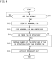
- FIG. 4 is a second flowchart illustrating the operation when an abnormality occurs in the ventilation system of the present disclosure.
- a control operation illustrated in FIG. 3 or FIG. 4 is executed when an abnormality occurs in the supply fan 22 and the exhaust fan 32.
- the control unit 16 determines whether the supply fan 22 and the exhaust fan 32 are normal (S01). In the present description, the control unit 16 determines that the supply fan 22 and the exhaust fan 32 are normal when there is no failure in the supply fan 22 and the exhaust fan 32 and the operation is performed in a state where the operation current values and the number of fan rotations are normal. In the present description, a state of the supply fan 22 not being normal is referred to as an abnormal state of the supply fan 22, and a state of the exhaust fan 32 not being normal is referred to as an abnormal state of the exhaust fan 32.
- step (S01) when the supply fan 22 and the exhaust fan 32 are normal (YES), the control unit 16 repeatedly executes step (S01).
- step (S01) when determining in step (S01) that the supply fan 22 and the exhaust fan 32 are abnormal (NO), the control unit 16 executes step (S02).
- step (S02) the control unit 16 identifies an abnormal fan (the supply fan 22 or the exhaust fan 32) of the supply fan 22 or the exhaust fan 32, and proceeds to step (S03).
- step (S03) the control unit 16 stops the fan (the supply fan 22 or the exhaust fan 32) identified as being abnormal of the supply fan 22 or the exhaust fan 32, and proceeds to step (S04).
- step (S04) the control unit 16 determines whether there are the supply fan 22 and the exhaust fan 32 in operation. When determining in step (S04) that there are the supply fan 22 and the exhaust fan 32 in operation (YES), the control unit 16 executes step (S05). When determining in step (S04) that there is not the supply fan 22 and the exhaust fan 32 in operation (NO), the control unit 16 proceeds to step (S08).
- step (S05) the control unit 16 increases the number of fan rotations of the fan in operation other than the stopped fan (the supply fan 22 or the exhaust fan 32) of the supply fan 22 or the exhaust fan 32, and proceeds to step (S06).
- step (S05) may be omitted, and step (S06) may be executed after step (S04) is executed.
- step (S06) the control unit 16 activates the notification unit 45 to notify to the user that the abnormal fan (the supply fan 22 or the exhaust fan 32) has been stopped, and proceeds to step (S07).
- step (S07) the control unit 16 determines whether an abnormality of the refrigerant circuit 50 is normal.
- a state of the refrigerant circuit 50 not being normal may be referred to as an abnormality of the refrigerant circuit 50.
- the "abnormality of the refrigerant circuit 50" herein means that the state value of the refrigerant circuit 50 exceeds the allowable range.
- step (S08) the control unit 16 stops the compressor 42 to protect the refrigerant circuit 50, and proceeds to step (S09).
- step (S09) the control unit 16 activates the notification unit 45 to notify to the user that the compressor 42 has been stopped, and ends the series of control operations.
- step (S04) determines whether the user has been stopped.
- step (S08) the control unit 16 causes the notification unit 45 to notify that the fans 22 and 32 and the compressor 42 have been stopped in step (S09).
- the control unit 16 continues the control of the ventilation system 10 in accordance with the flowchart illustrated in FIG. 3 .
- the ventilation system 10 can continue ventilation of the indoor space S1 even when an abnormality occurs in the supply fan 22 or the exhaust fan 32.
- the ventilation system 10 can further continue the operation of the compressor 42.
- temperature adjustment of the supply air SA or heat recovery from the exhaust air EA by the refrigerant circuit 50 can be continued by exerting the function of the fan (the supply fan 22 or the exhaust fan 32) in which no abnormality has occurred.
- the ventilation system 10 can suppress a decrease in a degree of comfort and a heat recovery efficiency of the indoor space S1 even when an abnormality occurs in the supply fan 22 or the exhaust fan 32.
- the ventilation system 10 of the present disclosure may perform control in accordance with the flow illustrated in FIG. 4 when an abnormality occurs in the supply fan 22 and the exhaust fan 32.
- step (S11) when the operation of the ventilation system 10 is started, the control unit 16 determines whether the supply fan 22 and the exhaust fan 32 are normal (S11). In step (S11), when the supply fan 22 and the exhaust fan 32 are normal (YES), the control unit 16 repeatedly executes step (S11). When determining in step (S11) that the supply fan 22 and the exhaust fan 32 are abnormal (NO), the control unit 16 executes step (S12).
- step (S12) the control unit 16 identifies an abnormal fan of the supply fan 22 or the exhaust fan 32, and proceeds to step (S13).
- step (S13) the control unit 16 stops the fan identified as being abnormal of the supply fan 22 or the exhaust fan 32, stops the compressor 42, and proceeds to step (S14).
- step (S14) the control unit 16 determines whether there are the supply fan 22 and the exhaust fan 32 in operation. When determining in step (S14) that there are the supply fan 22 and the exhaust fan 32 in operation (YES), the control unit 16 executes step (S15). When determining in step (S14) that there is not the supply fan 22 and the exhaust fan 32 in operation (NO), the control unit 16 proceeds to step (S16).
- step (S15) the control unit 16 increases the number of fan rotations of the fan in operation other than the stopped fan (the supply fan 22 or the exhaust fan 32) of the supply fan 22 or the exhaust fan 32, and proceeds to step (S16).
- step (S15) may be omitted, and step (S16) may be executed after step (S14) is executed.
- step (S16) the control unit 16 activates the notification unit 45 to notify to the user that the abnormal fan (the supply fan 22 or the exhaust fan 32) and the compressor 42 have been stopped, and ends the series of control operations (END). As long as there are the supply fan 22 and the exhaust fan 32 in operation, the control unit 16 continues the control of the ventilation system 10 in accordance with the flowchart illustrated in FIG. 4 .
- FIG. 5 is a schematic configuration diagram illustrating an arrangement state of the ventilation system according to the first embodiment of the present disclosure on a building.
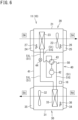
- FIG. 6 is a schematic configuration diagram of the ventilation system according to the first embodiment of the present disclosure.
- the first ventilation system 11 illustrated in FIG. 5 and FIG. 6 is the first embodiment of the ventilation system 10 of the present disclosure.
- the first ventilation system 11 includes one supply unit 20, one exhaust unit 30, a compressor unit 40, and a refrigerant circuit 50.
- the supply unit 20 and the exhaust unit 30 correspond to each other on a one-to-one basis.
- the supply unit 20, the exhaust unit 30, and the compressor unit 40 are integrally configured in the first ventilation system 11, but the units 20, 30, and 40 can be separated, and can be disposed separately.
- parts common to the first and second ventilation systems 11 and 12 are denoted by the same reference signs, and description of the parts denoted by the same reference signs will not be repeated.
- the first ventilation system 11 can be disposed in the outdoor space S2, for example.
- the blow-out port 25 of the supply unit 20 and the suction port 34 of the exhaust unit 30 are attached directly to an outer wall surface of a building B.
- a duct may be connected to the blow-out port 25 and the suction port 34 to be able to adjust a position where the supply air SA is released to the indoor space S1 and a position where the return air RA is sucked from the indoor space S1.
- a case where the first ventilation system 11 is disposed in the outdoor space S2 is exemplified.
- the entire first ventilation system 11 may be disposed in the indoor space S1, or the supply unit 20, the exhaust unit 30, and the compressor unit 40 may be separated, some of the units may be disposed in the outdoor space S2, and the other units may be disposed in the indoor space S1.
- the control unit 16 When determining that the supply fan 22 or the exhaust fan 32 is abnormal during the operation of the first ventilation system 11 (S01), the control unit 16 identifies the abnormal fan (S02), and stops the abnormal fan (the supply fan 22 or the exhaust fan 32) (S03). When the stopped fan is the supply fan 22, the control unit 16 continues the operation of the exhaust fan 32. In this case, the first ventilation system 11 can continue ventilation (third ventilation) with only the exhaust fan 32 for the indoor space S1. When the stopped fan is the exhaust fan 32, the control unit 16 continues the operation of the supply fan 22. In this case, the first ventilation system 11 can continue ventilation (second ventilation) with only the supply fan 22 for the indoor space S1.
- the control unit 16 After stopping the abnormal fan (the supply fan 22 or the exhaust fan 32), the control unit 16 increases the number of fan rotations of the fan (the supply fan 22 or the exhaust fan 32) that is continuing the operation to increase an air volume of the fan (S05).
- the first ventilation system 11 can suppress a decrease in a ventilation amount of the indoor space S1 due to the stop of the supply fan 22 or the exhaust fan 32.
- the control unit 16 After stopping the abnormal fan (the supply fan 22 or the exhaust fan 32), the control unit 16 activates the notification unit 45 disposed in the indoor space S1 to notify to the user or the like that the supply fan 22 or the exhaust fan 32 has been stopped (S06). By the activation of the notification unit 45 at this time, the user can know that a change has occurred in the ventilation state of the indoor space S1.
- the control unit 16 After stopping the abnormal fan (the supply fan 22 or the exhaust fan 32) and acquiring the state value of the refrigerant circuit 50, when determining that the state value exceeds the allowable range, the control unit 16 stops the compressor 42 (S08).
- the first ventilation system 11 when an abnormality occurs in the supply fan 22 or the exhaust fan 32, it is possible to continue ventilation of the indoor space S1 while performing heat exchange and heat recovery by the refrigerant circuit 50 as much as possible.
- the control unit 16 activates the notification unit 45 to notify to the user or the like that the compressor 42 has stopped (S09).
- the notification unit 45 By the activation of the notification unit 45 at this time, the user can know that there is a possibility that a change occurs in the temperature of the indoor space S1.
- the control unit 16 When determining that the supply fan 22 or the exhaust fan 32 is abnormal during the operation of the first ventilation system 11 (S11), the control unit 16 identifies the abnormal fan (S12), and stops the abnormal fan (the supply fan 22 or the exhaust fan 32) and the compressor 42 (S13).
- FIG. 7 is a schematic configuration diagram of the ventilation system according to the second embodiment of the present disclosure.
- the second ventilation system 12 illustrated in FIG. 7 is the second embodiment of the ventilation system 10 of the present disclosure.
- the second ventilation system 12 is different from the first ventilation system 11 described above in that a plurality of supply units 20 and a plurality of exhaust units 30 are provided.
- the second ventilation system 12 ventilates a room R1 provided in the indoor space S1.
- the second ventilation system 12 includes two supply units 20 and two exhaust units 30 for the room R1.
- one of the two supply units 20 is referred to as a first supply unit 20A
- the other supply unit 20 is referred to as a second supply unit 20B
- one of the two exhaust units 30 is referred to as a first exhaust unit 30A
- the other exhaust unit 30 is referred to as a second exhaust unit 30B.
- the first supply unit 20A includes a first supply fan 22A
- the second supply unit 20B includes a second supply fan 22B
- the first exhaust unit 30A includes a first exhaust fan 32A
- the second exhaust unit 30B includes a second exhaust fan 32B.
- the second ventilation system 12 includes two supply units 20 and two exhaust units 30, the number of the supply units 20 and the number of the exhaust units 30 in the second ventilation system 12 are not limited to two, and may be two or more, or one of the numbers may be one. In the second ventilation system 12 according to the present embodiment, the number of supply units 20 and the number of exhaust units 30 may be different.
- the outside air OA taken in from an outside air inlet 28 provided in the outer wall of the building B is distributed to the supply units 20A and 20B by a supply duct 29.
- the plurality of supply fans 22 supplies the supply air SA to the room R1
- the plurality of exhaust fans 32 releases the return air RA having a volume balanced with a volume of the supply air SA from the room R1 as the exhaust air EA.
- a total air volume of the supply air SA by the plurality of supply units 20 and a total air volume of the exhaust air EA by the plurality of exhaust units 30 are balanced.
- the control unit 16 identifies a fan having an abnormality (S02) and stops the abnormal fan (S03).
- the control unit 16 continues the operation of the second supply fan 22B, the first exhaust fan 32A, and the second exhaust fan 32B.
- the first ventilation system 11 can continue ventilation (first ventilation) for the indoor space S1.
- the second ventilation system 12 even when any of the fans is stopped, it is possible to continue the ventilation of the indoor space S1 (first ventilation) by continuing the operation of the remaining fans.
- the control unit 16 increases the number of fan rotations of the second supply fan 22B of the fans continuing the operation to increase a supply amount of the second supply fan 22B.
- the first ventilation system 11 can suppress a decrease in the ventilation amount of the indoor space S1 due to the stop of the first supply fan 22A.
- the second ventilation system 12 when the first supply fan 22A is stopped, the number of fan rotations of not only the second supply fan 22B but also the numbers of fan rotations of the first exhaust fan 32A and the second exhaust fan 32B may be further increased. In other words, in the second ventilation system 12, when any fan is stopped, the numbers of fan rotations of all the remaining fans may be increased to suppress a decrease in the ventilation amount of the indoor space S1.
- the control unit 16 When determining that any of the first supply fan 22A, the second supply fan 22B, the first exhaust fan 32A, or the second exhaust fan 32B (S11) is abnormal during the operation of the second ventilation system 12, the control unit 16 identifies a fan having an abnormality (S12) and stops the abnormal fan and the compressor 42 (S13). When the stopped fan is the first supply fan 22A, the control unit 16 continues the operation of the second supply fan 22B, the first exhaust fan 32A, and the second exhaust fan 32B. In this case, the second ventilation system 12 can continue ventilation (first ventilation) with the second supply fan 22B, the first exhaust fan 32A, and the second exhaust fan 32B for the indoor space S1.
- the ventilation system 10 having such a configuration can perform preventive maintenance on the supply fan 22 and the exhaust fan 32 before occurrence of abnormality and can suppress occurrence of abnormality in the supply fan 22 or the exhaust fan 32 during operation. As a result, the ventilation amount of the indoor space S 1 can be reliably secured.
Landscapes
- Engineering & Computer Science (AREA)
- Mechanical Engineering (AREA)
- General Engineering & Computer Science (AREA)
- Chemical & Material Sciences (AREA)
- Combustion & Propulsion (AREA)
- Physics & Mathematics (AREA)
- Thermal Sciences (AREA)
- Health & Medical Sciences (AREA)
- Biomedical Technology (AREA)
- Air Conditioning Control Device (AREA)
- Ventilation (AREA)
Abstract
Description
- The present disclosure relates to a ventilation system.
- Conventionally, there is known an air conditioning system including a refrigerant circuit in which a refrigerant flows and a heat source-side unit including a compressor, a plurality of utilization-side units that air-conditions an indoor space, a supply unit including a supply fan and a first heat exchanger, and an exhaust unit including an exhaust fan and a second heat exchanger are connected by a refrigerant pipe (see, for example, PATENT LITERATURE 1). The air conditioning system can ventilate the indoor space by the supply fan and the exhaust fan.
- PATENT LITERATURE 1:
Japanese Laid-Open Patent Publication No. H3-20573 - As in the air conditioning system, in a system including a refrigerant circuit that can be used by switching one of a first heat exchanger or a second heat exchanger as an evaporator and the other as a condenser, when any one of a supply fan or an exhaust fan cannot produce a predetermined air volume, the entire system is conventionally stopped in order to protect the refrigerant circuit. Therefore, in the system, when an abnormality occurs in any one of the supply fan or the exhaust fan, ventilation of the indoor space cannot be continued.
- An object of the present disclosure is to enable continuous ventilation of a ventilation system including a refrigerant circuit, a supply fan, and an exhaust fan.
-
- (1) A ventilation system of the present disclosure includes a refrigerant circuit in which a compressor, a first heat exchanger, and a second heat exchanger are connected by a refrigerant pipe and a refrigerant flows inside, a supply fan that supplies air from an outdoor space to an indoor space through the first heat exchanger, an exhaust fan that exhausts air in the indoor space to the outdoor space through the second heat exchanger, and a control unit, in which the control unit determines whether the supply fan and the exhaust fan are normal, and when determining that one of the supply fan or the exhaust fan is abnormal, the control unit stops the one of the supply fan or the exhaust fan determined to be abnormal and continues an operation of another one of the supply fan or the exhaust fan determined to be normal.
- The ventilation system of the present disclosure including the refrigerant circuit, the supply fan, and the exhaust fan can continue ventilation of the indoor space when an abnormality occurs in the supply fan or the exhaust fan.
- (2) In the ventilation system of the present disclosure, the control unit preferably acquires a state value of the refrigerant circuit, and when determining that the state value exceeds an allowable range, the control unit preferably stops the compressor.
- In this case, when an abnormality occurs in the supply fan or the exhaust fan, it is possible to continue the ventilation of the indoor space while performing heat exchange and heat recovery by the refrigerant circuit as much as possible.
- (3) In the ventilation system of the present disclosure, when determining that the supply fan or the exhaust fan is abnormal, the control unit preferably stops the compressor.
- In this case, the ventilation of the indoor space can be reliably continued when an abnormality occurs in the supply fan or the exhaust fan.
- (4) The ventilation system of the present disclosure preferably further includes a notification unit that notifies an abnormality of the supply fan or the exhaust fan, in which when determining that the supply fan or the exhaust fan is abnormal, the control unit activates the notification unit.
- In this case, the notification unit can notify to a user or the like occurrence of the abnormality in the supply fan or the exhaust fan.
- (5) In the ventilation system of the present disclosure, the control unit preferably determines whether the supply fan is normal on the basis of a correlation between the number of fan rotations and the operation current value of the supply fan, and determines whether the exhaust fan is normal on the basis of a correlation between the number of fan rotations and the operation current value of the exhaust fan.
- In this case, the control unit can determine whether the supply fan or the exhaust fan is abnormal without a sensor provided separately.
- (6) In the ventilation system of the present disclosure, when determining that one of the supply fan or the exhaust fan is abnormal, the control unit preferably increases the number of fan rotations of another one of the supply fan or the exhaust fan determined to be normal.
- In this case, it is possible to suppress a decrease in the ventilation amount of the indoor space when the supply fan or the exhaust fan in which the abnormality has occurred is stopped.
- (7) In the ventilation system of the present disclosure, the supply fan preferably includes a first supply fan and a second supply fan, the exhaust fan preferably includes a first exhaust fan and a second exhaust fan, the control unit preferably determines whether the first supply fan, the second supply fan, the first exhaust fan, and the second exhaust fan are normal, and when determining that any one of the supply fan or the exhaust fan is abnormal, the control unit preferably continues an operation of a remaining one of the supply fan or the exhaust fan determined to be normal.
- In this case, the ventilation system including the refrigerant circuit and a plurality of supply fans and exhaust fans can continue the ventilation of the indoor space when an abnormality occurs in the supply fans or the exhaust fans.
- (8) In the ventilation system of the present disclosure, when determining that any one of the first supply fan, the second supply fan, the first exhaust fan, or the second exhaust fan is abnormal, the control unit preferably increases the number of fan rotations of the supply fan or the exhaust fan determined to be normal.
- In this case, it is possible to suppress a decrease in the ventilation amount of the indoor space when the supply fan or the exhaust fan in which the abnormality has occurred is stopped.
- (9) In the ventilation system of the present disclosure, the control unit preferably predicts an abnormality of the supply fan on the basis of operation data of the supply fan and predicts an abnormality of the exhaust fan on the basis of operation data of the exhaust fan.
- In this case, it is possible to perform preventive maintenance on the supply fan and the exhaust fan before occurrence of abnormality and suppress occurrence of abnormality in the supply fan or the exhaust fan during operation. As a result, the ventilation amount of the indoor space can be reliably secured.
-
-
FIG. 1 is a schematic configuration diagram of a ventilation system of the present disclosure. -
FIG. 2 is a control block diagram of the ventilation system of the present disclosure. -
FIG. 3 is a first flowchart illustrating an operation when an abnormality occurs in the ventilation system of the present disclosure. -
FIG. 4 is a second flowchart illustrating the operation when an abnormality occurs in the ventilation system of the present disclosure. -
FIG. 5 is a schematic configuration diagram illustrating an arrangement state of a ventilation system according to a first embodiment of the present disclosure on a building. -
FIG. 6 is a schematic configuration diagram of the ventilation system according to the first embodiment of the present disclosure. -
FIG. 7 is a schematic configuration diagram of a ventilation system according to a second embodiment of the present disclosure. -
FIG. 1 is a schematic configuration diagram of a ventilation system of the present disclosure.FIG. 2 is a control block diagram of the ventilation system of the present disclosure. In the following description, aventilation system 10 according to a first embodiment (seeFIG. 5 andFIG. 6 ) is referred to as afirst ventilation system 11, and aventilation system 10 according to a second embodiment (seeFIG. 7 ) is referred to as asecond ventilation system 12. In the following description, when simply referred to as the "ventilation system 10", the configuration common to thefirst ventilation system 11 and thesecond ventilation system 12 will be described. - The
ventilation system 10 of the present disclosure illustrated inFIG. 1 is installed on a building such as an office building or a factory, and achieves ventilation of a target space in the building. Theventilation system 10 includes asupply unit 20, anexhaust unit 30, acompressor unit 40, and arefrigerant circuit 50. - As shown in
FIG. 1 , thesupply unit 20 includes afirst casing 21, asupply fan 22, and afirst heat exchanger 23. Thefirst casing 21 according to the present embodiment is a cubic box constituted with a panel member having a heat insulating property, and has side surfaces provided with asuction port 24 and a blow-outport 25. Thesupply fan 22 and thefirst heat exchanger 23 are disposed in thefirst casing 21. When thesupply fan 22 is driven, thesupply unit 20 takes air (outside air OA) in an outdoor space (hereinafter, referred to as an outdoor space S2, seeFIG. 5 andFIG. 7 ) into thefirst casing 21, exchanges heat of the taken air with a refrigerant in thefirst heat exchanger 23, and then supplies the air (supply air SA) from the blow-outport 25 toward an indoor space (hereinafter, referred to as an indoor space S1, seeFIG. 5 andFIG. 7 ). - The
first heat exchanger 23 constitutes therefrigerant circuit 50 described later. Thefirst heat exchanger 23 is a cross-fin tube type or microchannel type heat exchanger, and is used to exchange heat between the refrigerant flowing in thefirst heat exchanger 23 and the air (outside air OA) in the outdoor space S2. - The
supply unit 20 includes a supplyair temperature sensor 26 and an outsideair temperature sensor 27. The supplyair temperature sensor 26 is disposed in an airflow after passing through thefirst heat exchanger 23 in thefirst casing 21, and detects a temperature T1 of the supply air SA (hereinafter, referred to as a blow-out air temperature T1). The outsideair temperature sensor 27 is disposed in an airflow before passing through thefirst heat exchanger 23 in thefirst casing 21, and detects a temperature T2 of the outside air OA (hereinafter, referred to as an outside air temperature T2). - The
supply unit 20 includes a first heatexchange temperature sensor 55 and a firstrefrigerant temperature sensor 56. The first heatexchange temperature sensor 55 detects a temperature Tb1 of the first heat exchanger 23 (in other words, of the refrigerant in the first heat exchanger 23). The firstrefrigerant temperature sensor 56 detects a temperature Ta2 of the refrigerant after passing through (an outlet of) thefirst heat exchanger 23. The first heatexchange temperature sensor 55 may be a pressure sensor that detects a pressure in thefirst heat exchanger 23. In this case, the refrigerant temperature in thefirst heat exchanger 23 is converted from a detection value of the pressure. - The
exhaust unit 30 includes asecond casing 31, anexhaust fan 32, and asecond heat exchanger 33. Thesecond casing 31 according to the present embodiment is a cubic box constituted with a panel member having a heat insulating property, and has side surfaces provided with asuction port 34 and a blow-outport 35. Theexhaust fan 32 and thesecond heat exchanger 33 are disposed in thesecond casing 31. When theexhaust fan 32 is driven, theexhaust unit 30 takes air (return air RA) in the indoor space S1 into thesecond casing 31, exchanges heat of the taken air with a refrigerant in thesecond heat exchanger 33, and then releases the air (exhaust air EA) from the blow-outport 35 toward the outdoor space S2. - The
second heat exchanger 33 constitutes therefrigerant circuit 50 described later. Thesecond heat exchanger 33 is a cross-fin tube type or microchannel type heat exchanger, and is used to exchange heat between the refrigerant flowing in thesecond heat exchanger 33 and the air (return air RA) in the indoor space S1. - The
exhaust unit 30 includes a returnair temperature sensor 36. The returnair temperature sensor 36 is disposed in an airflow before passing through thesecond heat exchanger 33 in thesecond casing 31, and detects a temperature T3 of the air flowing into thesecond heat exchanger 33. In the following description, the temperature T3 is referred to as a suction air temperature T3. - The
exhaust unit 30 includes a second heatexchange temperature sensor 57 and a secondrefrigerant temperature sensor 58. The second heatexchange temperature sensor 57 detects a temperature Tb2 of the second heat exchanger 33 (in other words, of the refrigerant in the second heat exchanger 33). The secondrefrigerant temperature sensor 58 detects a temperature Tb3 of the refrigerant after passing through (an outlet of) thesecond heat exchanger 33. The second heatexchange temperature sensor 57 may be a pressure sensor that detects a pressure in thesecond heat exchanger 33. In this case, the refrigerant temperature in thefirst heat exchanger 23 is converted from a detection value of the pressure. - As described above, the
ventilation system 10 of the present disclosure includes thesupply fan 22 and theexhaust fan 32. Although theventilation system 10 illustrated inFIG. 1 includes onesupply fan 22 and oneexhaust fan 32, in theventilation system 10 of the present disclosure, the number ofsupply fans 22 may be two or more, and the number ofexhaust fans 32 may be two or more. - The
compressor unit 40 includes athird casing 41, acompressor 42, a four-way switching valve 43, and anexpansion valve 44. Although thecompressor unit 40 according to the present embodiment includes thethird casing 41, thethird casing 41 may be omitted. In this case, thecompressor 42 and the four-way switching valve 43 are preferably accommodated in thefirst casing 21 of thesupply unit 20 or thesecond casing 31 of theexhaust unit 30. Although theexpansion valve 44 is accommodated in thecompressor unit 40 in theventilation system 10 according to the present embodiment, theexpansion valve 44 may be accommodated in thefirst casing 21 of thesupply unit 20 or thesecond casing 31 of theexhaust unit 30. - The
compressor unit 40 includes alow pressure sensor 52, adischarge pressure sensor 53, and adischarge temperature sensor 54. Thelow pressure sensor 52 detects a pressure PL of the refrigerant sucked into thecompressor 42. In the following description, the pressure PL is also referred to as a low pressure PL. Thedischarge pressure sensor 53 detects a pressure PH of the refrigerant discharged from thecompressor 42. In the following description, the pressure PH is also referred to as a high pressure PH. Thedischarge temperature sensor 54 detects a temperature Ta1 of the refrigerant discharged from thecompressor 42. - The
compressor 42 sucks a low-pressure gaseous refrigerant and discharges a high-pressure gaseous refrigerant. Thecompressor 42 includes a motor having the number of operating revolutions adjustable in accordance with inverter control. Thecompressor 42 is of a variable capacity type (performance variable type) having capacity (performance) variable in accordance with inverter control of the motor. Alternatively, thecompressor 42 may be of a constant capacity type. Thecompressor 42 used in theventilation system 10 of the present disclosure may be configured by connecting two or more compressors in parallel. - The four-
way switching valve 43 reverses the flow of refrigerant in the refrigerant pipe, and switches and supplies the refrigerant discharged from thecompressor 42 to either thefirst heat exchanger 23 or thesecond heat exchanger 33. Accordingly, theventilation system 10 can switch between a cooling operation of cooling the outside air OA and a heating operation of heating the outside air OA. Theexpansion valve 44 is constituted by an electric valve capable of adjusting the flow rate and the pressure of the refrigerant. In theventilation system 10, an opening degree of theexpansion valve 44 is controlled to adjust the pressure of the refrigerant to be supplied to thefirst heat exchanger 23 or thesecond heat exchanger 33. - The
refrigerant circuit 50 includes thecompressor 42, the four-way switching valve 43, theexpansion valve 44, thefirst heat exchanger 23, thesecond heat exchanger 33, and a refrigerant pipe 51 (aliquid pipe 51L and agas pipe 51G) connecting the above components. Therefrigerant circuit 50 circulates the refrigerant between thefirst heat exchanger 23 and thesecond heat exchanger 33. - In the
ventilation system 10 having the above configuration, when the outside air OA is cooled and supplied by theair supply unit 20, the four-way switching valve 43 is held in a state indicated by solid lines inFIG. 1 . The high-temperature and high-pressure gaseous refrigerant discharged from thecompressor 42 flows into thesecond heat exchanger 33 of theexhaust unit 30 through the four-way switching valve 43. At this time, thesecond heat exchanger 33 functions as a condenser, and the refrigerant exchanges heat with the return air RA by the activation of theexhaust fan 32 to be condensed and liquefied. The liquefied refrigerant is decompressed by theexpansion valve 44 and flows into thefirst heat exchanger 23. At this time, thefirst heat exchanger 23 functions as an evaporator, and in thefirst heat exchanger 23, the refrigerant exchanges heat with the outside air OA and evaporates. The outside air OA cooled by the evaporation of the refrigerant is supplied to the indoor space S1 as the supply air SA by thesupply fan 22. The refrigerant evaporated in thefirst heat exchanger 23 returns to thecompressor unit 40 through the refrigerant pipe 51 (gas pipe 51G), and is sucked into thecompressor 42 through the four-way switching valve 43. - In the
ventilation system 10 having the above configuration, when the outside air OA is heated and supplied by thesupply unit 20, the four-way switching valve 43 is held in a state indicated by broken lines inFIG. 1 . The high-temperature and high-pressure gaseous refrigerant discharged from thecompressor 42 passes through the four-way switching valve 43 and flows into thefirst heat exchanger 23 of thesupply unit 20. At this time, thefirst heat exchanger 23 functions as a condenser, and the refrigerant exchanges heat with the outside air OA to be condensed and liquefied in thefirst heat exchanger 23. The outside air OA heated by the condensation of the refrigerant is supplied to theindoor space S 1 by thesupply fan 22. The refrigerant liquefied in thefirst heat exchanger 23 reaches thecompressor unit 40 through the refrigerant pipe 51 (liquid pipe 51L), is decompressed to a predetermined low pressure by theexpansion valve 44, and further flows into thesecond heat exchanger 33. At this time, thesecond heat exchanger 33 functions as an evaporator, and the refrigerant exchanges heat with the return air RA and evaporates in thesecond heat exchanger 33. The refrigerant evaporated and vaporized in thesecond heat exchanger 33 is sucked into thecompressor 42 through the four-way switching valve 43. - In the
ventilation system 10 according to the present embodiment, therefrigerant circuit 50 includes the four-way switching valve 43, and thefirst heat exchanger 23 can be switched and used as an evaporator and a condenser by the four-way switching valve 43. Alternatively, the four-way switching valve 43 in theventilation system 10 may be omitted. In this case, thefirst heat exchanger 23 can be used as an evaporator or a condenser. -
FIG. 2 is a control block diagram illustrating theventilation system 10. As illustrated inFIG. 2 , theventilation system 10 includes acontrol unit 16. Thecontrol unit 16 is configured to control an operation of theventilation system 10, and is constituted by, for example, a microcomputer including a processor such as a CPU and a memory such as a RAM or a ROM. Thecontrol unit 16 may be implemented as hardware with use of an LSI, an ASIC, an FPGA, or the like. Thecontrol unit 16 exerts a predetermined function when the processor executes a program installed in the memory. - The
control unit 16 is connected to theair supply fan 22, theexhaust fan 32, thecompressor 42, the four-way switching valve 43, theexpansion valve 44, and anotification unit 45. Thecontrol unit 16 is connected to the supplyair temperature sensor 26, the outsideair temperature sensor 27, and the returnair temperature sensor 36. - The
control unit 16 is connected to thelow pressure sensor 52, thedischarge pressure sensor 53, thedischarge temperature sensor 54, the first heatexchange temperature sensor 55, the firstrefrigerant temperature sensor 56, the second heatexchange temperature sensor 57, and the secondrefrigerant temperature sensor 58 provided at various locations in therefrigerant circuit 50. In the present description, detection values of thesensors 52 to 58 provided in therefrigerant circuit 50 are also referred to as state values of therefrigerant circuit 50. Thecontrol unit 16 knows an operation state of therefrigerant circuit 50 on the basis of the state values of therefrigerant circuit 50. Specifically, for example, when the outside air OA is heated in theirsupply unit 20 to supply air, thecontrol unit 16 calculates a saturation temperature TS of thesecond heat exchanger 33 functioning as an evaporator on the basis of the detection value (high pressure PH) of thedischarge pressure sensor 53, acquires the low pressure PL of therefrigerant circuit 50 from the detection value of thelow pressure sensor 52, and acquires an evaporation temperature TE of thesecond heat exchanger 33 from the detection value (temperature Tb2) of the second heatexchange temperature sensor 57. The saturation temperature TS, the low pressure PL, and the evaporation temperature TE are examples of the state values of therefrigerant circuit 50. - The
control unit 16 stores a threshold for determining whether each state value of therefrigerant circuit 50 is normal or abnormal. When the acquired state value exceeds the threshold, thecontrol unit 16 determines that therefrigerant circuit 50 has reached a state in which a function of therefrigerant circuit 50 cannot be maintained. In the present description, the state in which therefrigerant circuit 50 cannot maintain the function of therefrigerant circuit 50 is also referred to as "the state value of therefrigerant circuit 50 exceeds an allowable range". - The
control unit 16 is configured to be able to individually acquire information related to operation current values and numbers of fan rotations of thesupply fan 22 and theexhaust fan 32. Thecontrol unit 16 determines whether thesupply fan 22 is normal on the basis of a correlation between the number of fan rotations and the operation current value of thesupply fan 22, and determines whether theexhaust fan 32 is normal on the basis of a correlation between the number of fan rotations and the operation current value of theexhaust fan 32. Theventilation system 10 having such a configuration allows thecontrol unit 16 to determine whether thesupply fan 22 or theexhaust fan 32 is normal by without a sensor provided separately. - The
control unit 16 has a function of determining whether there is a sign of abnormality occurring in thesupply fan 22 and theexhaust fan 32 on the basis of information related to the individual operation current values and numbers of fan rotations of thesupply fan 22 and theexhaust fan 32. For example, thecontrol unit 16 determines whether there is a sign of abnormality occurrence on the basis of the operation current values at a time of starting thesupply fan 22 and theexhaust fan 32 and the correlation between the operation current values and the numbers of fan rotations of thesupply fan 22 and theexhaust fan 32. - The
notification unit 45 according to the present embodiment is a remote controller for a user to operate and stop theventilation system 10, change settings of theventilation system 10, and the like, and is disposed in the target space (indoor space S1) where ventilation is performed by theventilation system 10. Thenotification unit 45 notifies occurrence of an abnormality in theventilation system 10 by a sound (including buzzer sound, voice, or the like) or a display (including lighting of a lamp, display by a liquid crystal panel, or the like). In the present embodiment, the remote controller for theventilation system 10 also serves as thenotification unit 45, but thenotification unit 45 may be configured by a device other than the remote controller. The place wherenotification unit 45 is disposed is not required to be the indoor space S1, and may be, for example, a place where an administrator of theventilation system 10 is present (central monitoring room). - When the
control unit 16 determines that there is a sign of abnormality occurrence in either thesupply fan 22 or theexhaust fan 32, thenotification unit 45 notifies the sign. The user can know a fan having a high possibility of occurrence of abnormality by the information presented by thenotification unit 45. The user can repair the fans before an abnormality occurs in thesupply fan 22 and theexhaust fan 32. Thecontrol unit 16 predicts occurrence of an abnormality in thesupply fan 22 and theexhaust fan 32, and thenotification unit 45 notifies the occurrence of the abnormality. Therefore, theventilation system 10 of the present disclosure can suppress the occurrence of the abnormality that needs to be stopped during use and can continue to operate reliably. -
FIG. 3 is a first flowchart illustrating the operation when an abnormality occurs in the ventilation system of the present disclosure.FIG. 4 is a second flowchart illustrating the operation when an abnormality occurs in the ventilation system of the present disclosure. In theventilation system 10 of the present disclosure, a control operation illustrated inFIG. 3 orFIG. 4 is executed when an abnormality occurs in thesupply fan 22 and theexhaust fan 32. - The control operation of the
ventilation system 10 illustrated inFIG. 3 will be described. As illustrated inFIG. 3 , when the operation of theventilation system 10 is started, thecontrol unit 16 determines whether thesupply fan 22 and theexhaust fan 32 are normal (S01). In the present description, thecontrol unit 16 determines that thesupply fan 22 and theexhaust fan 32 are normal when there is no failure in thesupply fan 22 and theexhaust fan 32 and the operation is performed in a state where the operation current values and the number of fan rotations are normal. In the present description, a state of thesupply fan 22 not being normal is referred to as an abnormal state of thesupply fan 22, and a state of theexhaust fan 32 not being normal is referred to as an abnormal state of theexhaust fan 32. - In step (S01), when the
supply fan 22 and theexhaust fan 32 are normal (YES), thecontrol unit 16 repeatedly executes step (S01). When determining in step (S01) that thesupply fan 22 and theexhaust fan 32 are abnormal (NO), thecontrol unit 16 executes step (S02). - In step (S02), the
control unit 16 identifies an abnormal fan (thesupply fan 22 or the exhaust fan 32) of thesupply fan 22 or theexhaust fan 32, and proceeds to step (S03). - In step (S03), the
control unit 16 stops the fan (thesupply fan 22 or the exhaust fan 32) identified as being abnormal of thesupply fan 22 or theexhaust fan 32, and proceeds to step (S04). - In step (S04), the
control unit 16 determines whether there are thesupply fan 22 and theexhaust fan 32 in operation. When determining in step (S04) that there are thesupply fan 22 and theexhaust fan 32 in operation (YES), thecontrol unit 16 executes step (S05). When determining in step (S04) that there is not thesupply fan 22 and theexhaust fan 32 in operation (NO), thecontrol unit 16 proceeds to step (S08). - In step (S05), the
control unit 16 increases the number of fan rotations of the fan in operation other than the stopped fan (thesupply fan 22 or the exhaust fan 32) of thesupply fan 22 or theexhaust fan 32, and proceeds to step (S06). In theventilation system 10 of the present disclosure, step (S05) may be omitted, and step (S06) may be executed after step (S04) is executed. - In step (S06), the
control unit 16 activates thenotification unit 45 to notify to the user that the abnormal fan (thesupply fan 22 or the exhaust fan 32) has been stopped, and proceeds to step (S07). - In step (S07), the
control unit 16 determines whether an abnormality of therefrigerant circuit 50 is normal. In the present description, a state of therefrigerant circuit 50 not being normal may be referred to as an abnormality of therefrigerant circuit 50. The "abnormality of therefrigerant circuit 50" herein means that the state value of therefrigerant circuit 50 exceeds the allowable range. When determining in step (S07) that therefrigerant circuit 50 is normal (YES), thecontrol unit 16 repeatedly executes step (S07) at predetermined time intervals to continuously check whether therefrigerant circuit 50 is normal. When determining in step (S07) that therefrigerant circuit 50 is abnormal (NO), thecontrol unit 16 executes step (S08). - In step (S08), the
control unit 16 stops thecompressor 42 to protect therefrigerant circuit 50, and proceeds to step (S09). - In step (S09), the
control unit 16 activates thenotification unit 45 to notify to the user that thecompressor 42 has been stopped, and ends the series of control operations. When the determination in step (S04) is NO and the processing proceeds from step (S04) to step (S08), thecontrol unit 16 causes thenotification unit 45 to notify that thefans compressor 42 have been stopped in step (S09). As long as there are thesupply fan 22 and theexhaust fan 32 in operation, thecontrol unit 16 continues the control of theventilation system 10 in accordance with the flowchart illustrated inFIG. 3 . - By performing control according to the flow illustrated in
FIG. 3 , theventilation system 10 can continue ventilation of the indoor space S1 even when an abnormality occurs in thesupply fan 22 or theexhaust fan 32. When no abnormality occurs in therefrigerant circuit 50, theventilation system 10 can further continue the operation of thecompressor 42. In this case, temperature adjustment of the supply air SA or heat recovery from the exhaust air EA by therefrigerant circuit 50 can be continued by exerting the function of the fan (thesupply fan 22 or the exhaust fan 32) in which no abnormality has occurred. By performing control in accordance with the flow illustrated inFIG. 3 , theventilation system 10 can suppress a decrease in a degree of comfort and a heat recovery efficiency of the indoor space S1 even when an abnormality occurs in thesupply fan 22 or theexhaust fan 32. - The
ventilation system 10 of the present disclosure may perform control in accordance with the flow illustrated inFIG. 4 when an abnormality occurs in thesupply fan 22 and theexhaust fan 32. - Here, the control operation of the
ventilation system 10 illustrated inFIG. 4 will be described. As illustrated inFIG. 4 , when the operation of theventilation system 10 is started, thecontrol unit 16 determines whether thesupply fan 22 and theexhaust fan 32 are normal (S11). In step (S11), when thesupply fan 22 and theexhaust fan 32 are normal (YES), thecontrol unit 16 repeatedly executes step (S11). When determining in step (S11) that thesupply fan 22 and theexhaust fan 32 are abnormal (NO), thecontrol unit 16 executes step (S12). - In step (S12), the
control unit 16 identifies an abnormal fan of thesupply fan 22 or theexhaust fan 32, and proceeds to step (S13). - In step (S13), the
control unit 16 stops the fan identified as being abnormal of thesupply fan 22 or theexhaust fan 32, stops thecompressor 42, and proceeds to step (S14). - In step (S14), the
control unit 16 determines whether there are thesupply fan 22 and theexhaust fan 32 in operation. When determining in step (S14) that there are thesupply fan 22 and theexhaust fan 32 in operation (YES), thecontrol unit 16 executes step (S15). When determining in step (S14) that there is not thesupply fan 22 and theexhaust fan 32 in operation (NO), thecontrol unit 16 proceeds to step (S16). - In step (S15), the
control unit 16 increases the number of fan rotations of the fan in operation other than the stopped fan (thesupply fan 22 or the exhaust fan 32) of thesupply fan 22 or theexhaust fan 32, and proceeds to step (S16). In theventilation system 10 of the present disclosure, step (S15) may be omitted, and step (S16) may be executed after step (S14) is executed. - In step (S16), the
control unit 16 activates thenotification unit 45 to notify to the user that the abnormal fan (thesupply fan 22 or the exhaust fan 32) and thecompressor 42 have been stopped, and ends the series of control operations (END). As long as there are thesupply fan 22 and theexhaust fan 32 in operation, thecontrol unit 16 continues the control of theventilation system 10 in accordance with the flowchart illustrated inFIG. 4 . -
FIG. 5 is a schematic configuration diagram illustrating an arrangement state of the ventilation system according to the first embodiment of the present disclosure on a building.FIG. 6 is a schematic configuration diagram of the ventilation system according to the first embodiment of the present disclosure. Thefirst ventilation system 11 illustrated inFIG. 5 andFIG. 6 is the first embodiment of theventilation system 10 of the present disclosure. Thefirst ventilation system 11 includes onesupply unit 20, oneexhaust unit 30, acompressor unit 40, and arefrigerant circuit 50. In other words, in thefirst ventilation system 11, thesupply unit 20 and theexhaust unit 30 correspond to each other on a one-to-one basis. In a mode illustrated inFIG. 5 andFIG. 6 , thesupply unit 20, theexhaust unit 30, and thecompressor unit 40 are integrally configured in thefirst ventilation system 11, but theunits second ventilation systems - As illustrated in
FIG. 5 , thefirst ventilation system 11 can be disposed in the outdoor space S2, for example. In the present embodiment, the blow-outport 25 of thesupply unit 20 and thesuction port 34 of theexhaust unit 30 are attached directly to an outer wall surface of a building B. In thefirst ventilation system 11, a duct may be connected to the blow-outport 25 and thesuction port 34 to be able to adjust a position where the supply air SA is released to the indoor space S1 and a position where the return air RA is sucked from the indoor space S1. In the present embodiment, a case where thefirst ventilation system 11 is disposed in the outdoor space S2 is exemplified. However, the entirefirst ventilation system 11 may be disposed in the indoor space S1, or thesupply unit 20, theexhaust unit 30, and thecompressor unit 40 may be separated, some of the units may be disposed in the outdoor space S2, and the other units may be disposed in the indoor space S1. - Here, a case will be described where the
first ventilation system 11 is controlled in accordance with the flow illustrated inFIG. 3 . When determining that thesupply fan 22 or theexhaust fan 32 is abnormal during the operation of the first ventilation system 11 (S01), thecontrol unit 16 identifies the abnormal fan (S02), and stops the abnormal fan (thesupply fan 22 or the exhaust fan 32) (S03). When the stopped fan is thesupply fan 22, thecontrol unit 16 continues the operation of theexhaust fan 32. In this case, thefirst ventilation system 11 can continue ventilation (third ventilation) with only theexhaust fan 32 for the indoor space S1. When the stopped fan is theexhaust fan 32, thecontrol unit 16 continues the operation of thesupply fan 22. In this case, thefirst ventilation system 11 can continue ventilation (second ventilation) with only thesupply fan 22 for the indoor space S1. - After stopping the abnormal fan (the
supply fan 22 or the exhaust fan 32), thecontrol unit 16 increases the number of fan rotations of the fan (thesupply fan 22 or the exhaust fan 32) that is continuing the operation to increase an air volume of the fan (S05). Thus, thefirst ventilation system 11 can suppress a decrease in a ventilation amount of the indoor space S1 due to the stop of thesupply fan 22 or theexhaust fan 32. - After stopping the abnormal fan (the
supply fan 22 or the exhaust fan 32), thecontrol unit 16 activates thenotification unit 45 disposed in the indoor space S1 to notify to the user or the like that thesupply fan 22 or theexhaust fan 32 has been stopped (S06). By the activation of thenotification unit 45 at this time, the user can know that a change has occurred in the ventilation state of the indoor space S1. - After stopping the abnormal fan (the
supply fan 22 or the exhaust fan 32) and acquiring the state value of therefrigerant circuit 50, when determining that the state value exceeds the allowable range, thecontrol unit 16 stops the compressor 42 (S08). In thefirst ventilation system 11, when an abnormality occurs in thesupply fan 22 or theexhaust fan 32, it is possible to continue ventilation of the indoor space S1 while performing heat exchange and heat recovery by therefrigerant circuit 50 as much as possible. - After stopping the
refrigerant circuit 50, thecontrol unit 16 activates thenotification unit 45 to notify to the user or the like that thecompressor 42 has stopped (S09). By the activation of thenotification unit 45 at this time, the user can know that there is a possibility that a change occurs in the temperature of the indoor space S1. - Here, a case will be described where the
first ventilation system 11 is controlled in accordance with the flow illustrated inFIG. 4 . When determining that thesupply fan 22 or theexhaust fan 32 is abnormal during the operation of the first ventilation system 11 (S11), thecontrol unit 16 identifies the abnormal fan (S12), and stops the abnormal fan (thesupply fan 22 or the exhaust fan 32) and the compressor 42 (S13). - When the
first ventilation system 11 is controlled in accordance with the flowchart illustrated inFIG. 4 , ventilation of the indoor space S1 can be reliably continued in a case where an abnormality occurs in thesupply fan 22 or theexhaust fan 32. -
FIG. 7 is a schematic configuration diagram of the ventilation system according to the second embodiment of the present disclosure. Thesecond ventilation system 12 illustrated inFIG. 7 is the second embodiment of theventilation system 10 of the present disclosure. Thesecond ventilation system 12 is different from thefirst ventilation system 11 described above in that a plurality ofsupply units 20 and a plurality ofexhaust units 30 are provided. - As illustrated in
FIG. 7 , thesecond ventilation system 12 ventilates a room R1 provided in the indoor space S1. Thesecond ventilation system 12 includes twosupply units 20 and twoexhaust units 30 for the room R1. In the following description, one of the twosupply units 20 is referred to as afirst supply unit 20A, theother supply unit 20 is referred to as asecond supply unit 20B, one of the twoexhaust units 30 is referred to as afirst exhaust unit 30A, and theother exhaust unit 30 is referred to as asecond exhaust unit 30B. Thefirst supply unit 20A includes afirst supply fan 22A, and thesecond supply unit 20B includes asecond supply fan 22B. Thefirst exhaust unit 30A includes afirst exhaust fan 32A, and thesecond exhaust unit 30B includes asecond exhaust fan 32B. Although thesecond ventilation system 12 according to the present embodiment includes twosupply units 20 and twoexhaust units 30, the number of thesupply units 20 and the number of theexhaust units 30 in thesecond ventilation system 12 are not limited to two, and may be two or more, or one of the numbers may be one. In thesecond ventilation system 12 according to the present embodiment, the number ofsupply units 20 and the number ofexhaust units 30 may be different. - In the
second ventilation system 12, the outside air OA taken in from anoutside air inlet 28 provided in the outer wall of the building B is distributed to thesupply units supply duct 29. In thesecond ventilation system 12, the plurality ofsupply fans 22 supplies the supply air SA to the room R1, and the plurality ofexhaust fans 32 releases the return air RA having a volume balanced with a volume of the supply air SA from the room R1 as the exhaust air EA. In thesecond ventilation system 12, a total air volume of the supply air SA by the plurality ofsupply units 20 and a total air volume of the exhaust air EA by the plurality ofexhaust units 30 are balanced. - Here, a case will be described where the
second ventilation system 12 is controlled in accordance with the flow illustrated inFIG. 3 . In the following description, a description will be mainly given of a part different in operation from a case where thefirst ventilation system 11 is controlled in accordance with the flow illustrated inFIG. 3 , and a description of a part common in operation will be omitted.
when determining that any of thefirst supply fan 22A, thesecond supply fan 22B, thefirst exhaust fan 32A, or thesecond exhaust fan 32B (S01) is abnormal during the operation of thesecond ventilation system 12, thecontrol unit 16 identifies a fan having an abnormality (S02) and stops the abnormal fan (S03). For example, when the stopped fan is thefirst supply fan 22A, thecontrol unit 16 continues the operation of thesecond supply fan 22B, thefirst exhaust fan 32A, and thesecond exhaust fan 32B. In this case, thefirst ventilation system 11 can continue ventilation (first ventilation) for the indoor space S1. In thesecond ventilation system 12, even when any of the fans is stopped, it is possible to continue the ventilation of the indoor space S1 (first ventilation) by continuing the operation of the remaining fans. - For example, when the stopped fan is the
first supply fan 22A, thecontrol unit 16 increases the number of fan rotations of thesecond supply fan 22B of the fans continuing the operation to increase a supply amount of thesecond supply fan 22B. By bringing a balance between the supply amount and the discharge amount close to a normal state, thefirst ventilation system 11 can suppress a decrease in the ventilation amount of the indoor space S1 due to the stop of thefirst supply fan 22A. In thesecond ventilation system 12, when thefirst supply fan 22A is stopped, the number of fan rotations of not only thesecond supply fan 22B but also the numbers of fan rotations of thefirst exhaust fan 32A and thesecond exhaust fan 32B may be further increased. In other words, in thesecond ventilation system 12, when any fan is stopped, the numbers of fan rotations of all the remaining fans may be increased to suppress a decrease in the ventilation amount of the indoor space S1. - Here, a case will be described where the
second ventilation system 12 is controlled in accordance with the flow illustrated inFIG. 4 . When determining that any of thefirst supply fan 22A, thesecond supply fan 22B, thefirst exhaust fan 32A, or thesecond exhaust fan 32B (S11) is abnormal during the operation of thesecond ventilation system 12, thecontrol unit 16 identifies a fan having an abnormality (S12) and stops the abnormal fan and the compressor 42 (S13). When the stopped fan is thefirst supply fan 22A, thecontrol unit 16 continues the operation of thesecond supply fan 22B, thefirst exhaust fan 32A, and thesecond exhaust fan 32B. In this case, thesecond ventilation system 12 can continue ventilation (first ventilation) with thesecond supply fan 22B, thefirst exhaust fan 32A, and thesecond exhaust fan 32B for the indoor space S1. - When the
second ventilation system 12 is controlled in accordance with the flowchart illustrated inFIG. 4 , ventilation of the indoor space S1 can be reliably continued in a case where an abnormality occurs in any of thefirst supply fan 22A, thesecond supply fan 22B, thefirst exhaust fan 32A, or thesecond exhaust fan 32B. -
- (1) The
first ventilation system 11 described in the above embodiment includes therefrigerant circuit 50 in which thecompressor 42, thefirst heat exchanger 23, and thesecond heat exchanger 33 are connected by therefrigerant pipe 51 and the refrigerant flows, thesupply fan 22 that supplies air in the outdoor space S2 to the indoor space S1 through thefirst heat exchanger 23, theexhaust fan 32 that exhausts air in the indoor space S1 to the outdoor space S2 through thesecond heat exchanger 33, and thecontrol unit 16. Thecontrol unit 16 determines whether thesupply fan 22 and theexhaust fan 32 are normal. When determining that one of thesupply fan 22 or theexhaust fan 32 is abnormal, thecontrol unit 16 stops the one of thesupply fan 22 or theexhaust fan 32 determined to be abnormal and continues an operation of another one of thesupply fan 22 or theexhaust fan 32 determined to be normal.
In this case, theventilation system 10 including therefrigerant circuit 50, thesupply fan 22, and theexhaust fan 32 can continue the ventilation of the indoor space S1 when an abnormality occurs in thesupply fan 22 or theexhaust fan 32. - (2) In the
ventilation system 10 described in the above embodiment, thecontrol unit 16 acquires a state value of therefrigerant circuit 50, and when determining that the state value exceeds an allowable range, thecontrol unit 16 stops thecompressor 42.
In theventilation system 10 having such a configuration, when an abnormality occurs in thesupply fan 22 or theexhaust fan 32, it is possible to continue ventilation of the indoor space S1 while performing heat exchange and heat recovery by therefrigerant circuit 50 as much as possible. - (3) In the
ventilation system 10 described in the above embodiment, when determining that thesupply fan 22 or theexhaust fan 32 is abnormal, thecontrol unit 16 stops thecompressor 42.
In theventilation system 10 having such a configuration, the ventilation of the indoor space S1 can be reliably continued in a case where an abnormality occurs in thesupply fan 22 or theexhaust fan 32. - (4) The
ventilation system 10 described in the above embodiment further includes thenotification unit 45 that notifies an abnormality of thesupply fan 22 or theexhaust fan 32. When determining that thesupply fan 22 or theexhaust fan 32 is abnormal, thecontrol unit 16 activates thenotification unit 45.
In theventilation system 10 having such a configuration, thenotification unit 45 can notify to a user or the like occurrence of the abnormality in thesupply fan 22 or theexhaust fan 32. - (5) In the
ventilation system 10 described in the above embodiment, thecontrol unit 16 determines whether thesupply fan 22 is normal on the basis of a correlation between the number of fan rotations and the operation current value of thesupply fan 22, and determines whether theexhaust fan 32 is normal on the basis of a correlation between the number of fan rotations and the operation current value of theexhaust fan 32.
Theventilation system 10 having such a configuration allows thecontrol unit 16 to determine whether thesupply fan 22 or theexhaust fan 32 is abnormal without a sensor provided separately. - (6) In the
first ventilation system 11 described in the above embodiment, when determining that one of thesupply fan 22 or theexhaust fan 32 is abnormal, thecontrol unit 16 increases the number of fan rotations of the another one of thesupply fan 22 or theexhaust fan 32 determined to be normal.
Thefirst ventilation system 11 having such a configuration can suppress a decrease in the ventilation amount of theindoor space S 1 when thesupply fan 22 or theexhaust fan 32 in which the abnormality has occurred is stopped. - (7) In the
second ventilation system 12 described in the above embodiment, thesupply fan 22 includes thefirst supply fan 22A and thesecond supply fan 22B, and theexhaust fan 32 includes thefirst exhaust fan 32A and thesecond exhaust fan 32B. Thecontrol unit 16 determines whether thefirst supply fan 22A, thesecond supply fan 22B, thefirst exhaust fan 32A, and thesecond exhaust fan 32B are normal, and continues the operation of the remaining thesupply fan 22 or theexhaust fan 32 determined to be normal when determining that any one of thesupply fan 22 or theexhaust fan 32 is abnormal.
In this case, thesecond ventilation system 12 including therefrigerant circuit 50 and a plurality ofsupply fans 22 andexhaust fans 32 can continue the ventilation of the indoor space S1 when an abnormality occurs in thesupply fans 22 or theexhaust fans 32. - (8) In the
second ventilation system 12 described in the above embodiment, when determining that any one of thefirst supply fan 22A, thesecond supply fan 22B, thefirst exhaust fan 32A, or thesecond exhaust fan 32B is abnormal, thecontrol unit 16 increases the number of fan rotations of thesupply fan 22 or theexhaust fan 32 determined to be normal.
Theventilation system 10 having such a configuration can suppress a decrease in the ventilation amount of the indoor space S1 when thesupply fan 22 or theexhaust fan 32 in which the abnormality has occurred is stopped. - (9) In the
ventilation system 10 described in the above embodiment, thecontrol unit 16 predicts an abnormality of thesupply fan 22 on the basis of operation data of thesupply fan 22 and predicts an abnormality of theexhaust fan 32 on the basis of operation data of theexhaust fan 32. - The
ventilation system 10 having such a configuration can perform preventive maintenance on thesupply fan 22 and theexhaust fan 32 before occurrence of abnormality and can suppress occurrence of abnormality in thesupply fan 22 or theexhaust fan 32 during operation. As a result, the ventilation amount of theindoor space S 1 can be reliably secured. - The present disclosure should not be limited to the above exemplification, but is intended to include any modification recited in the claims within meanings and a scope equivalent to those of the claims.
-
- 10
- ventilation system
- 11
- first ventilation system
- 12
- second ventilation system
- 16
- control unit
- 22
- supply fan
- 22A
- first supply fan
- 22B
- second supply fan
- 23
- first heat exchanger
- 32
- exhaust fan
- 32A
- first exhaust fan
- 32B
- second exhaust fan
- 33
- second heat exchanger
- 42
- compressor
- 45
- notification unit
- 50
- refrigerant circuit
- 51
- refrigerant pipe
- S1
- indoor space
- S2
- outdoor space
Claims (9)
- A ventilation system (10, 11) comprising:a refrigerant circuit (50) in which a compressor (42), a first heat exchanger (23), and a second heat exchanger (33) are connected by a refrigerant pipe (51) and a refrigerant flows inside;a supply fan (22) that supplies air from an outdoor space (S2) to an indoor space (S1) through the first heat exchanger (23);an exhaust fan (32) that exhausts air in the indoor space (S1) to the outdoor space (S2) through the second heat exchanger (33); anda control unit (16), whereinthe control unit (16) determines whether the supply fan (22) and the exhaust fan (32) are normal, and, when determining that one of the supply fan (22) or the exhaust fan (32) is abnormal, the control unit (16) stops the one of the supply fan (22) or the exhaust fan (32) determined to be abnormal and continues an operation of another one of the supply fan (22) or the exhaust fan (32) determined to be normal.
- The ventilation system (10) according to claim 1, wherein the control unit (16) acquires a state value of the refrigerant circuit (50), and, when determining that the state value exceeds an allowable range, the control unit (16) stops the compressor (42).
- The ventilation system (10) according to claim 1, wherein when determining that the supply fan (22) or the exhaust fan (32) is abnormal,
the control unit (16) stops the compressor (42). - The ventilation system (10) according to any one of claims 1 to 3, further comprising a notification unit (45) that notifies an abnormality of the supply fan (22) or the exhaust fan (32), whereinwhen determining that the supply fan (22) or the exhaust fan (32) is abnormal,the control unit (16) activates the notification unit (45).
- The ventilation system (10) according to any one of claims 1 to 4, wherein the control unit (16) determines whether the supply fan (22) is normal on a basis of a correlation between a number of fan rotations and an operation current value of the supply fan (22), and determines whether the exhaust fan (32) is normal on a basis of a correlation between a number of fan rotations and an operation current value of the exhaust fan (32).
- The ventilation system (11) according to any one of claims 1 to 5, wherein when determining that one of the supply fan (22) or the exhaust fan (32) is abnormal,
the control unit (16) increases the number of fan rotations of another one of the supply fan (22) or the exhaust fan (32) determined to be normal. - The ventilation system (10, 12) according to any one of claims 1 to 6, whereinthe supply fan (22) includes a first supply fan (22A) and a second supply fan (22B),the exhaust fan (32) includes a first exhaust fan (32A) and a second exhaust fan (32B),the control unit (16) determines whether the first supply fan (22A), the second supply fan (22B), the first exhaust fan (32A), and the second exhaust fan (32B) are normal, and, when determining that any one of the supply fan (22) or the exhaust fan (32) is abnormal, the control unit (16) continues an operation of a remaining one of the supply fan (22) or the exhaust fan (32) determined to be normal.
- The ventilation system (12) according to claim 7, wherein, when determining that any one of the first supply fan (22A), the second supply fan (22B), the first exhaust fan (32A), or the second exhaust fan (32B) is abnormal, the control unit (16) increases the number of fan rotations of the supply fan (22) or the exhaust fan (32) determined to be normal.
- The ventilation system (10) according to any one of claims 1 to 8, wherein the control unit (16) predicts an abnormality of the supply fan (22) on a basis of operation data of the supply fan (22), and predicts an abnormality of the exhaust fan (32) on a basis of operation data of the exhaust fan (32).
Applications Claiming Priority (2)
| Application Number | Priority Date | Filing Date | Title |
|---|---|---|---|
| JP2021205442A JP7295454B1 (en) | 2021-12-17 | 2021-12-17 | ventilation system |
| PCT/JP2022/040691 WO2023112530A1 (en) | 2021-12-17 | 2022-10-31 | Ventilation system |
Publications (3)
| Publication Number | Publication Date |
|---|---|
| EP4450883A1 true EP4450883A1 (en) | 2024-10-23 |
| EP4450883A4 EP4450883A4 (en) | 2025-03-12 |
| EP4450883B1 EP4450883B1 (en) | 2026-02-25 |
Family
ID=86772742
Family Applications (1)
| Application Number | Title | Priority Date | Filing Date |
|---|---|---|---|
| EP22907063.6A Active EP4450883B1 (en) | 2021-12-17 | 2022-10-31 | Ventilation system |
Country Status (7)
| Country | Link |
|---|---|
| US (1) | US20240328648A1 (en) |
| EP (1) | EP4450883B1 (en) |
| JP (1) | JP7295454B1 (en) |
| CN (1) | CN118401785A (en) |
| AU (1) | AU2022408269B2 (en) |
| ES (1) | ES3065411T3 (en) |
| WO (1) | WO2023112530A1 (en) |
Family Cites Families (13)
| Publication number | Priority date | Publication date | Assignee | Title |
|---|---|---|---|---|
| JPH0320573A (en) | 1989-06-19 | 1991-01-29 | Sanyo Electric Co Ltd | Air-conditioning apparatus |
| JPH11132512A (en) * | 1997-10-27 | 1999-05-21 | Toshio Sakurazawa | Attic ventilation system |
| JP2001289493A (en) * | 2000-04-06 | 2001-10-19 | Sanyo Electric Co Ltd | Air conditioner control method |
| JP4513381B2 (en) * | 2004-03-31 | 2010-07-28 | ダイキン工業株式会社 | Air conditioning system |
| JP2006275431A (en) * | 2005-03-29 | 2006-10-12 | Kyocera Corp | Ventilator motor control method |
| JP2007010216A (en) * | 2005-06-30 | 2007-01-18 | Daikin Ind Ltd | Ventilation device |
| JP2009109124A (en) * | 2007-10-31 | 2009-05-21 | Daikin Ind Ltd | Humidity control device |
| JP5625640B2 (en) * | 2010-09-06 | 2014-11-19 | 富士電機株式会社 | Multi-unit fan drive device and failure processing method thereof |
| JP5930370B2 (en) * | 2011-12-28 | 2016-06-08 | 株式会社ノーリツ | Control device for water heater and fan motor |
| JP5668766B2 (en) * | 2013-02-07 | 2015-02-12 | ダイキン工業株式会社 | Ventilation equipment |
| JP2015108468A (en) * | 2013-12-04 | 2015-06-11 | パナソニックIpマネジメント株式会社 | Fan filter unit and control system for fan filter unit |
| JP6453469B2 (en) * | 2015-07-30 | 2019-01-16 | 三菱電機株式会社 | Ventilation system |
| JP7157722B2 (en) * | 2019-09-30 | 2022-10-20 | ダイキン工業株式会社 | air conditioning ventilation system |
-
2021
- 2021-12-17 JP JP2021205442A patent/JP7295454B1/en active Active
-
2022
- 2022-10-31 ES ES22907063T patent/ES3065411T3/en active Active
- 2022-10-31 AU AU2022408269A patent/AU2022408269B2/en active Active
- 2022-10-31 WO PCT/JP2022/040691 patent/WO2023112530A1/en not_active Ceased
- 2022-10-31 CN CN202280083006.2A patent/CN118401785A/en active Pending
- 2022-10-31 EP EP22907063.6A patent/EP4450883B1/en active Active
-
2024
- 2024-06-13 US US18/742,652 patent/US20240328648A1/en active Pending
Also Published As
| Publication number | Publication date |
|---|---|
| AU2022408269A1 (en) | 2024-07-04 |
| AU2022408269B2 (en) | 2024-07-25 |
| EP4450883B1 (en) | 2026-02-25 |
| JP2023090475A (en) | 2023-06-29 |
| EP4450883A4 (en) | 2025-03-12 |
| JP7295454B1 (en) | 2023-06-21 |
| ES3065411T3 (en) | 2026-05-06 |
| WO2023112530A1 (en) | 2023-06-22 |
| CN118401785A (en) | 2024-07-26 |
| US20240328648A1 (en) | 2024-10-03 |
Similar Documents
| Publication | Publication Date | Title |
|---|---|---|
| US12416439B2 (en) | Refrigerant cycle apparatus | |
| EP3358278B1 (en) | Refrigerating device | |
| US11536502B2 (en) | Refrigerant cycle apparatus | |
| EP4040060A1 (en) | Air conditioning and ventilation system | |
| JP7257782B2 (en) | air conditioning system | |
| US10976090B2 (en) | Air conditioner | |
| EP3115715B1 (en) | Refrigeration cycle system | |
| EP4481287A1 (en) | Air-conditioning system | |
| CN108351139A (en) | Refrigeration cycle device and refrigerant leakage detection method | |
| CN113137715A (en) | Control method for compressor frequency of multi-split air conditioner and multi-split air conditioner | |
| US20240019147A1 (en) | System and method for monitoring charge level of hvac system | |
| US10914487B2 (en) | Low load mode of HVAC system | |
| EP4450883B1 (en) | Ventilation system | |
| JP7438342B2 (en) | air conditioner | |
| JP2003042520A (en) | Air conditioner and operation control method thereof | |
| JP7237182B2 (en) | air conditioner | |
| EP4411268A1 (en) | Ventilation device | |
| KR101186326B1 (en) | Air-Condition and the control method for the same | |
| JP7590654B2 (en) | Ventilation system | |
| JP7697858B2 (en) | Blower | |
| KR20200073471A (en) | Control method for air conditioner | |
| US12320561B2 (en) | HVAC unit with expansion device | |
| KR20080013402A (en) | Control Method of Inverter Compressor and Air Conditioner | |
| EP4166865A1 (en) | Refrigerant circuit device assessment system | |
| KR20050105747A (en) | Multi-type air conditioner and the compressor control method of it |
Legal Events
| Date | Code | Title | Description |
|---|---|---|---|
| STAA | Information on the status of an ep patent application or granted ep patent |
Free format text: STATUS: THE INTERNATIONAL PUBLICATION HAS BEEN MADE |
|
| PUAI | Public reference made under article 153(3) epc to a published international application that has entered the european phase |
Free format text: ORIGINAL CODE: 0009012 |
|
| STAA | Information on the status of an ep patent application or granted ep patent |
Free format text: STATUS: REQUEST FOR EXAMINATION WAS MADE |
|
| 17P | Request for examination filed |
Effective date: 20240704 |
|
| AK | Designated contracting states |
Kind code of ref document: A1 Designated state(s): AL AT BE BG CH CY CZ DE DK EE ES FI FR GB GR HR HU IE IS IT LI LT LU LV MC ME MK MT NL NO PL PT RO RS SE SI SK SM TR |
|
| P01 | Opt-out of the competence of the unified patent court (upc) registered |
Free format text: CASE NUMBER: APP_1117/2025 Effective date: 20250108 |
|
| A4 | Supplementary search report drawn up and despatched |
Effective date: 20250211 |
|
| RIC1 | Information provided on ipc code assigned before grant |
Ipc: F04D 27/00 20060101ALI20250206BHEP Ipc: F24F 7/08 20060101ALI20250206BHEP Ipc: F24F 7/007 20060101ALI20250206BHEP Ipc: F24F 11/86 20180101ALI20250206BHEP Ipc: F24F 11/52 20180101ALI20250206BHEP Ipc: F24F 11/38 20180101ALI20250206BHEP Ipc: F24F 11/32 20180101AFI20250206BHEP |
|
| DAV | Request for validation of the european patent (deleted) | ||
| DAX | Request for extension of the european patent (deleted) | ||
| GRAP | Despatch of communication of intention to grant a patent |
Free format text: ORIGINAL CODE: EPIDOSNIGR1 |
|
| STAA | Information on the status of an ep patent application or granted ep patent |
Free format text: STATUS: GRANT OF PATENT IS INTENDED |
|
| INTG | Intention to grant announced |
Effective date: 20251023 |
|
| GRAS | Grant fee paid |
Free format text: ORIGINAL CODE: EPIDOSNIGR3 |
|
| GRAA | (expected) grant |
Free format text: ORIGINAL CODE: 0009210 |
|
| STAA | Information on the status of an ep patent application or granted ep patent |
Free format text: STATUS: THE PATENT HAS BEEN GRANTED |
|
| AK | Designated contracting states |
Kind code of ref document: B1 Designated state(s): AL AT BE BG CH CY CZ DE DK EE ES FI FR GB GR HR HU IE IS IT LI LT LU LV MC ME MK MT NL NO PL PT RO RS SE SI SK SM TR |
|
| REG | Reference to a national code |
Ref country code: CH Ref legal event code: F10 Free format text: ST27 STATUS EVENT CODE: U-0-0-F10-F00 (AS PROVIDED BY THE NATIONAL OFFICE) Effective date: 20260225 Ref country code: GB Ref legal event code: FG4D |
|
| REG | Reference to a national code |
Ref country code: DE Ref legal event code: R096 Ref document number: 602022031373 Country of ref document: DE |
|
| REG | Reference to a national code |
Ref country code: IE Ref legal event code: FG4D |
|
| REG | Reference to a national code |
Ref country code: ES Ref legal event code: FG2A Ref document number: 3065411 Country of ref document: ES Kind code of ref document: T3 Effective date: 20260506 |
|
| REG | Reference to a national code |
Ref country code: NL Ref legal event code: MP Effective date: 20260225 |
|
| PG25 | Lapsed in a contracting state [announced via postgrant information from national office to epo] |
Ref country code: RS Free format text: LAPSE BECAUSE OF FAILURE TO SUBMIT A TRANSLATION OF THE DESCRIPTION OR TO PAY THE FEE WITHIN THE PRESCRIBED TIME-LIMIT Effective date: 20260525 |
|
| PG25 | Lapsed in a contracting state [announced via postgrant information from national office to epo] |
Ref country code: PL Free format text: LAPSE BECAUSE OF FAILURE TO SUBMIT A TRANSLATION OF THE DESCRIPTION OR TO PAY THE FEE WITHIN THE PRESCRIBED TIME-LIMIT Effective date: 20260225 |
|
| PG25 | Lapsed in a contracting state [announced via postgrant information from national office to epo] |
Ref country code: GR Free format text: LAPSE BECAUSE OF FAILURE TO SUBMIT A TRANSLATION OF THE DESCRIPTION OR TO PAY THE FEE WITHIN THE PRESCRIBED TIME-LIMIT Effective date: 20260526 |
|
| REG | Reference to a national code |
Ref country code: LT Ref legal event code: MG9D |
|
| PG25 | Lapsed in a contracting state [announced via postgrant information from national office to epo] |
Ref country code: LT Free format text: LAPSE BECAUSE OF FAILURE TO SUBMIT A TRANSLATION OF THE DESCRIPTION OR TO PAY THE FEE WITHIN THE PRESCRIBED TIME-LIMIT Effective date: 20260225 |
|
| PG25 | Lapsed in a contracting state [announced via postgrant information from national office to epo] |
Ref country code: NO Free format text: LAPSE BECAUSE OF FAILURE TO SUBMIT A TRANSLATION OF THE DESCRIPTION OR TO PAY THE FEE WITHIN THE PRESCRIBED TIME-LIMIT Effective date: 20260525 |
|
| PG25 | Lapsed in a contracting state [announced via postgrant information from national office to epo] |
Ref country code: AT Free format text: LAPSE BECAUSE OF FAILURE TO SUBMIT A TRANSLATION OF THE DESCRIPTION OR TO PAY THE FEE WITHIN THE PRESCRIBED TIME-LIMIT Effective date: 20260225 Ref country code: FI Free format text: LAPSE BECAUSE OF FAILURE TO SUBMIT A TRANSLATION OF THE DESCRIPTION OR TO PAY THE FEE WITHIN THE PRESCRIBED TIME-LIMIT Effective date: 20260225 Ref country code: SE Free format text: LAPSE BECAUSE OF FAILURE TO SUBMIT A TRANSLATION OF THE DESCRIPTION OR TO PAY THE FEE WITHIN THE PRESCRIBED TIME-LIMIT Effective date: 20260225 |
|
| REG | Reference to a national code |
Ref country code: AT Ref legal event code: MK05 Ref document number: 1891208 Country of ref document: AT Kind code of ref document: T Effective date: 20260225 |
|
| PG25 | Lapsed in a contracting state [announced via postgrant information from national office to epo] |
Ref country code: HR Free format text: LAPSE BECAUSE OF FAILURE TO SUBMIT A TRANSLATION OF THE DESCRIPTION OR TO PAY THE FEE WITHIN THE PRESCRIBED TIME-LIMIT Effective date: 20260225 |
|
| PG25 | Lapsed in a contracting state [announced via postgrant information from national office to epo] |
Ref country code: IS Free format text: LAPSE BECAUSE OF FAILURE TO SUBMIT A TRANSLATION OF THE DESCRIPTION OR TO PAY THE FEE WITHIN THE PRESCRIBED TIME-LIMIT Effective date: 20260625 Ref country code: PT Free format text: LAPSE BECAUSE OF FAILURE TO SUBMIT A TRANSLATION OF THE DESCRIPTION OR TO PAY THE FEE WITHIN THE PRESCRIBED TIME-LIMIT Effective date: 20260625 |
|
| PG25 | Lapsed in a contracting state [announced via postgrant information from national office to epo] |
Ref country code: NL Free format text: LAPSE BECAUSE OF FAILURE TO SUBMIT A TRANSLATION OF THE DESCRIPTION OR TO PAY THE FEE WITHIN THE PRESCRIBED TIME-LIMIT Effective date: 20260225 |
|
| PG25 | Lapsed in a contracting state [announced via postgrant information from national office to epo] |
Ref country code: LV Free format text: LAPSE BECAUSE OF FAILURE TO SUBMIT A TRANSLATION OF THE DESCRIPTION OR TO PAY THE FEE WITHIN THE PRESCRIBED TIME-LIMIT Effective date: 20260225 |
|
| PG25 | Lapsed in a contracting state [announced via postgrant information from national office to epo] |
Ref country code: BG Free format text: LAPSE BECAUSE OF FAILURE TO SUBMIT A TRANSLATION OF THE DESCRIPTION OR TO PAY THE FEE WITHIN THE PRESCRIBED TIME-LIMIT Effective date: 20260225 |