EP4450853A1 - Valve assembly, integrated thermal management module and electric motor vehicle - Google Patents
Valve assembly, integrated thermal management module and electric motor vehicle Download PDFInfo
- Publication number
- EP4450853A1 EP4450853A1 EP23382378.0A EP23382378A EP4450853A1 EP 4450853 A1 EP4450853 A1 EP 4450853A1 EP 23382378 A EP23382378 A EP 23382378A EP 4450853 A1 EP4450853 A1 EP 4450853A1
- Authority
- EP
- European Patent Office
- Prior art keywords
- valve
- valve assembly
- conduit
- inner cavity
- thermal management
- Prior art date
- Legal status (The legal status is an assumption and is not a legal conclusion. Google has not performed a legal analysis and makes no representation as to the accuracy of the status listed.)
- Withdrawn
Links
Images





Classifications
-
- F—MECHANICAL ENGINEERING; LIGHTING; HEATING; WEAPONS; BLASTING
- F16—ENGINEERING ELEMENTS AND UNITS; GENERAL MEASURES FOR PRODUCING AND MAINTAINING EFFECTIVE FUNCTIONING OF MACHINES OR INSTALLATIONS; THERMAL INSULATION IN GENERAL
- F16K—VALVES; TAPS; COCKS; ACTUATING-FLOATS; DEVICES FOR VENTING OR AERATING
- F16K11/00—Multiple-way valves, e.g. mixing valves; Pipe fittings incorporating such valves
- F16K11/10—Multiple-way valves, e.g. mixing valves; Pipe fittings incorporating such valves with two or more closure members not moving as a unit
- F16K11/20—Multiple-way valves, e.g. mixing valves; Pipe fittings incorporating such valves with two or more closure members not moving as a unit operated by separate actuating members
-
- B—PERFORMING OPERATIONS; TRANSPORTING
- B60—VEHICLES IN GENERAL
- B60K—ARRANGEMENT OR MOUNTING OF PROPULSION UNITS OR OF TRANSMISSIONS IN VEHICLES; ARRANGEMENT OR MOUNTING OF PLURAL DIVERSE PRIME-MOVERS IN VEHICLES; AUXILIARY DRIVES FOR VEHICLES; INSTRUMENTATION OR DASHBOARDS FOR VEHICLES; ARRANGEMENTS IN CONNECTION WITH COOLING, AIR INTAKE, GAS EXHAUST OR FUEL SUPPLY OF PROPULSION UNITS IN VEHICLES
- B60K11/00—Arrangement in connection with cooling of propulsion units
- B60K11/02—Arrangement in connection with cooling of propulsion units with liquid cooling
-
- F—MECHANICAL ENGINEERING; LIGHTING; HEATING; WEAPONS; BLASTING
- F16—ENGINEERING ELEMENTS AND UNITS; GENERAL MEASURES FOR PRODUCING AND MAINTAINING EFFECTIVE FUNCTIONING OF MACHINES OR INSTALLATIONS; THERMAL INSULATION IN GENERAL
- F16K—VALVES; TAPS; COCKS; ACTUATING-FLOATS; DEVICES FOR VENTING OR AERATING
- F16K11/00—Multiple-way valves, e.g. mixing valves; Pipe fittings incorporating such valves
- F16K11/02—Multiple-way valves, e.g. mixing valves; Pipe fittings incorporating such valves with all movable sealing faces moving as one unit
- F16K11/08—Multiple-way valves, e.g. mixing valves; Pipe fittings incorporating such valves with all movable sealing faces moving as one unit comprising only taps or cocks
- F16K11/085—Multiple-way valves, e.g. mixing valves; Pipe fittings incorporating such valves with all movable sealing faces moving as one unit comprising only taps or cocks with cylindrical plug
- F16K11/0853—Multiple-way valves, e.g. mixing valves; Pipe fittings incorporating such valves with all movable sealing faces moving as one unit comprising only taps or cocks with cylindrical plug having all the connecting conduits situated in a single plane perpendicular to the axis of the plug
-
- F—MECHANICAL ENGINEERING; LIGHTING; HEATING; WEAPONS; BLASTING
- F16—ENGINEERING ELEMENTS AND UNITS; GENERAL MEASURES FOR PRODUCING AND MAINTAINING EFFECTIVE FUNCTIONING OF MACHINES OR INSTALLATIONS; THERMAL INSULATION IN GENERAL
- F16K—VALVES; TAPS; COCKS; ACTUATING-FLOATS; DEVICES FOR VENTING OR AERATING
- F16K11/00—Multiple-way valves, e.g. mixing valves; Pipe fittings incorporating such valves
- F16K11/10—Multiple-way valves, e.g. mixing valves; Pipe fittings incorporating such valves with two or more closure members not moving as a unit
- F16K11/20—Multiple-way valves, e.g. mixing valves; Pipe fittings incorporating such valves with two or more closure members not moving as a unit operated by separate actuating members
- F16K11/207—Multiple-way valves, e.g. mixing valves; Pipe fittings incorporating such valves with two or more closure members not moving as a unit operated by separate actuating members with two handles or actuating mechanisms at opposite sides of the housing
-
- F—MECHANICAL ENGINEERING; LIGHTING; HEATING; WEAPONS; BLASTING
- F16—ENGINEERING ELEMENTS AND UNITS; GENERAL MEASURES FOR PRODUCING AND MAINTAINING EFFECTIVE FUNCTIONING OF MACHINES OR INSTALLATIONS; THERMAL INSULATION IN GENERAL
- F16K—VALVES; TAPS; COCKS; ACTUATING-FLOATS; DEVICES FOR VENTING OR AERATING
- F16K27/00—Construction of housing; Use of materials therefor
- F16K27/06—Construction of housing; Use of materials therefor of taps or cocks
- F16K27/065—Construction of housing; Use of materials therefor of taps or cocks with cylindrical plugs
-
- B—PERFORMING OPERATIONS; TRANSPORTING
- B60—VEHICLES IN GENERAL
- B60K—ARRANGEMENT OR MOUNTING OF PROPULSION UNITS OR OF TRANSMISSIONS IN VEHICLES; ARRANGEMENT OR MOUNTING OF PLURAL DIVERSE PRIME-MOVERS IN VEHICLES; AUXILIARY DRIVES FOR VEHICLES; INSTRUMENTATION OR DASHBOARDS FOR VEHICLES; ARRANGEMENTS IN CONNECTION WITH COOLING, AIR INTAKE, GAS EXHAUST OR FUEL SUPPLY OF PROPULSION UNITS IN VEHICLES
- B60K1/00—Arrangement or mounting of electrical propulsion units
- B60K2001/003—Arrangement or mounting of electrical propulsion units with means for cooling the electrical propulsion units
-
- B—PERFORMING OPERATIONS; TRANSPORTING
- B60—VEHICLES IN GENERAL
- B60Y—INDEXING SCHEME RELATING TO ASPECTS CROSS-CUTTING VEHICLE TECHNOLOGY
- B60Y2304/00—Optimising design; Manufacturing; Testing
- B60Y2304/07—Facilitating assembling or mounting
- B60Y2304/072—Facilitating assembling or mounting by preassembled subunits
Definitions
- the present invention relates to valves and thermal management modules for electric motor vehicles.
- Electric vehicles are vehicles that are powered by one or more electric motors, which are powered by electric batteries. These batteries, in order to be efficient, must work within an optimal operating temperature range, so that in some cases it will be necessary to heat the batteries and in others to cool the batteries. Therefore, the thermal management of an electric vehicle is more complex compared to the thermal management of a conventional combustion vehicle, since apart from thermally managing the passenger compartment and the vehicle engine, the batteries must also be thermally managed.
- Said modules often include valves that fluidically connect different conduits, each conduit being associated with a vehicle component or element.
- US20150027572A1 describes a six-port valve comprising a main body with an inner cavity, the conduits of the valve being in fluidic communication with the inner cavity.
- the inner cavity is divided by an insulating wall which divides the inner cavity into two sections. In each section there is a movable valve body that can rotate, so that both valve bodies share an axial shaft that cooperates with an actuator to rotate both valve bodies. Rotating the valve bodies fluidically connects at least two of the six conduits of the valve.
- An object of the invention is to provide a valve assembly, as defined in the claims.
- Another object of the invention is to provide an integrated thermal management module for motor vehicles, as defined in the claims.
- the valve assembly of the invention comprises a first valve and a second valve, each valve comprising an inner cavity, a movable valve body arranged inside the inner cavity so that it can rotate, and a plurality of conduits in fluidic communication with the corresponding inner cavity.
- the valve assembly of the invention also comprises a connecting conduit that fluidically communicates the inner cavity of the first valve and the inner cavity of the second valve, so that the valve bodies of each valve can be arranged in such a way that at least one conduit of the first valve is fluidically connected to at least one conduit of the second valve.
- the integrated thermal management module for motor vehicles of the invention comprises the described valve assembly, a first actuator configured to move the valve body of the first valve, and a second actuator configured to move the valve body of the second valve, so that each valve body can rotate independently.
- Another object of the invention is to provide an electric motor vehicle comprising, elements to be conditioned, conditioning means and the integrated thermal management module of the invention, such that said module is configured to interact with any conditioner of the conditioning means to cool and/or heat any of the elements to be conditioned.
- valve assembly of the invention With the valve assembly of the invention, a higher thermal efficiency of the vehicle where the valve assembly is mounted is achieved in a simple and economical way.
- the valves of the valve assembly can work independently or jointly through the connection conduit, thus increasing the number of active conduits of the valve assembly in a simple way, which allows to increase the number of possible combinations to connect the different conduits of the valve assembly, that is to say, it allows to design a great variety of operating modes of the valve assembly, without complicating the design of the valve bodies to achieve this purpose, obtaining, due to the invention, a compact, reliable and economical valve assembly.
- valve assembly is integrated into a module, it facilitates its assembly in the vehicle, achieving a significant saving of space and parts in the vehicle, as the route of the hoses or tubes of the vehicle's hydraulic circuits is optimised.
- the integrated module of the invention which incorporates the valve assembly of the invention, allows the thermal efficiency of the vehicle to be improved, as will be detailed throughout the description.
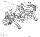
- Figure 1 shows a perspective view of a first embodiment of the integrated module 200 of the invention comprising a first embodiment of the valve assembly 100 according to a first embodiment of the invention.
- the valve assembly of the invention comprises a first valve 1 and a second valve 2, as shown in the non-limiting example of Figure 1 .
- Each valve 1 and 2 comprises an inner cavity 4, shown in Figure 4 , a movable valve body 3 arranged inside said inner cavity 4 so that it can rotate, as can be seen in the non-limiting example of Figure 3 , and a plurality of conduits 5 in fluidic communication with the corresponding inner cavity 4, as can be seen for example in Figure 2A .
- a corresponding valve body 3 is rotated, at least two of the conduits 5 of the valve assembly are fluidically connected.
- the valve assembly of the invention also comprises a connecting conduit 5a which fluidically communicates the inner cavity 4 of the first valve 1 and the inner cavity 4 of the second valve 2, so that the valve bodies 3 of each valve 1 and 2 can be arranged in such a way that at least one conduit 5 of the first valve 1 is fluidically connected with at least one conduit 5 of the second valve 2, allowing the fluid of a corresponding hydraulic circuit of the vehicle's thermal system to be directed from the conduit 5 of the first valve 1 to the conduit 5 of the second valve 2, or vice versa.
- valve assembly of the invention it is possible to improve the thermal efficiency of the vehicle in which the valve assembly is mounted in a simple and economical manner.
- the valves 1 and 2 of the valve assembly 100 can work independently or jointly through the connecting conduit 5a, thus allowing to increase the number of active conduits 5 of the valve assembly 100, i.e. conduits carrying a fluid, in a simple manner, and also allowing to increase the number of possible combinations for connecting the conduits 5 of the valve assembly 100 to each other, what makes it possible to design a wide variety of operating modes of the valve assembly 100, as will be detailed further below, without complicating the design of the valve bodies 3 for this purpose, thus obtaining, thanks to the invention, a reliable and economical compact valve assembly 100.
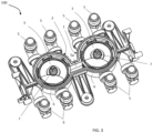
- FIG 3 shows a first embodiment of the valve assembly 100 and Figure 4 shows said valve assembly 100 but without the valve bodies 3 to better appreciate the inner cavity 4 of each valve 1 and 2.
- the valve assembly 100 comprises a main body 6, said main body 6 comprising the two inner cavities 4 such that both inner cavities 4 are fluidically communicated through the connecting conduit 5a, as shown in Figure 4 .
- Each valve body 3 is arranged in a respective inner cavity 4, as shown in figure 3 .
- each valve 1 and 2 comprises a closing cap 11 which is fitted after the corresponding valve body 3 has been assembled.
- the closing caps 11 are not shown.
- the inner cavities 4 of the two valves 1 and 2 are arranged on the same level, i.e., one next to the other according to a longitudinal direction X shown in the drawings, which corresponds to a horizontal aligned arrangement.
- the connecting conduit 5a is arranged between the two inner cavities 4, preferably also in the longitudinal direction X.
- each inner cavity 4 is joined together forming a single part, thus ensuring a tight seal, not only of each inner cavity 4 but also of the connecting conduit 5a.
- the inner cavities 4 of the two valves 1 and 2 are arranged on different levels, i.e., one above the other according to an axial direction Z shown in the drawings, which corresponds to a vertical arrangement, i.e., perpendicular to the longitudinal direction X.
- the connecting conduit 5a is preferably arranged on one side of the main body 6 of the valve assembly 110, in the axial direction Z, but could also be arranged, for example, in said axial direction Z but between the two corresponding inner cavities 4.
- Each valve 1 and 2 of the invention also comprises a shaft 7 cooperating with the corresponding valve body 3, each shaft 7 being configured to couple to a respective actuator 8, so that the corresponding valve body 3 can rotate.
- the two shafts 7 of the invention are not coupled to each other, so that each valve body 3 can rotate independently of each other.
- each valve body 3 and the respective shaft 7 form a single part, said shaft 7 protruding axially from the valve body 3 in the Z direction, in any of the described embodiments.
- the integrated thermal management module 200 of figure 1 comprising the valve assembly 100 of figure 3 , also comprises a first actuator 8 configured to move the valve body 3 of the first valve 1 and a second actuator 8 configured to move the valve body 3 of the second valve 2.
- the shaft 7 of each valve 1 and 2 is coupled to a respective actuator 8, as shown in Figure 1 or Figure 5 , so that thanks to each actuator 8, the valve bodies 3 of each valve 1 and 2 can rotate independently of each other.
- the module 200 also comprises a first hydraulic pump 10 which is in fluidic communication with at least one conduit 5 communicated with the inner cavity 4 of the first valve 1, and a second hydraulic pump 10 which is in fluidic communication with at least one conduit 5 communicated with the inner cavity 4 of the second valve 2, as shown in the diagram of Figure 7 .
- the hydraulic pumps 10 and the respective valves 1 and 2 of the valve assembly 100 of Figure 3 are arranged next to each other in the longitudinal direction X, each pump 10 being arranged at one end of the valve assembly 100, following the horizontal arrangement.
- the integrated thermal management module 210 of Figure 5 comprising the valve assembly 110 of Figure 6 and also comprising a respective actuator 8 configured to move the valve body 3 of the corresponding valve 1 or 2, so that each valve body 3 can rotate independently of each other, it also comprises a respective hydraulic pump 10 in fluidic communication with at least one conduit 5 communicated with the inner cavity 4 of the corresponding valve 1 or 2.
- first hydraulic pump 10 and the first valve 1 are arranged according to a first longitudinal direction X1 at a first level
- the second hydraulic pump 10 and the second valve 2 are arranged according to a second longitudinal direction X2 parallel to the first longitudinal direction X1, so that the respective valves 1 and 2 are arranged according to the axial direction Z, perpendicular to the longitudinal direction X, in accordance with the vertical arrangement of the valve assembly 110 of Figure 6 .
- the inner cavity 4 of each valve 1 and 2 is in fluidic communication with four conduits 5 and with the connecting conduit 5a, the respective valve body 3 being configured to selectively communicate at least two of said conduits 5 during use, so that the valve assembly 100 or 110 can operate as two independent four-way valves, or as an eight-way valve, thus increasing the number of possible combinations for communicating the conduits 5 of the valve assembly 100 or 110 with each other, allowing a wide variety of operating modes of the valve assembly 100 or 110 to be designed, which is very advantageous in an electric vehicle.
- valve body 3 of each valve 1 and 2 of the valve assembly of the invention 100 and 110 comprises three passage channels 9, said passage channels 9 being configured to allow the passage of a fluid between two conduits 5 of a respective valve 1 or 2, and/or between a conduit 5 of the respective valve 1 or 2 and the connecting conduit 5a.
- the valve assembly of the invention 100 and 110 comprises a main operating mode wherein the valve bodies 3 of the valves 1 and 2 are arranged such that a first conduit 5 of the first valve 1 is fluidically connected to a first conduit 5 of the second valve 2, a second conduit 5 of the first valve 1 can be fluidically connected to a third conduit 5 of the first valve 1, and a second conduit 5 of the second valve 2 can be fluidically connected to a third conduit 5 of the second valve 2, whereby the valve assembly 100 or 110 can simultaneously manage up to three independent hydraulic circuits.
- the main operating mode may in turn comprise a plurality of operating modes, as will be detailed further below in relation to the non-limiting examples of Figures 7A to 7E .
- valve assembly of the invention 100 and 110 also comprises a secondary operating mode in which the valve bodies 3 of the valves 1 and 2 are arranged in such a way that at least two conduits 5 of the first valve 1 are fluidically connected to each other, and/or at least two conduits 5 of the second valve 2 can be fluidically connected to each other, thus being able to manage simultaneously up to two independent hydraulic circuits for each valve 1 or 2.
- the secondary operating mode may in turn comprise a plurality of operating modes, as will be detailed further below in relation to the non-limiting example of Figure 7F .
- the electric motor vehicle of the invention comprises elements to be conditioned comprising a first element, preferably a battery pack 12, a second element, preferably at least one electric motor 13 (preferably with its corresponding power electronics, such as for example a power inverter), said at least one electric motor 13 being powered by the battery pack 12, and a third element, preferably a passenger compartment 14 where the passengers of the vehicle are accommodated, preferably seated, although the passengers could also stand in the passenger compartment 14, for example if the vehicle is a bus.
- a first element preferably a battery pack 12
- a second element preferably at least one electric motor 13 (preferably with its corresponding power electronics, such as for example a power inverter), said at least one electric motor 13 being powered by the battery pack 12, and a third element, preferably a passenger compartment 14 where the passengers of the vehicle are accommodated, preferably seated, although the passengers could also stand in the passenger compartment 14, for example if the vehicle is a bus.
- the vehicle also comprises at least three hydraulic pumps 10, the battery pack 12, the electric motor 13 and the passenger compartment 14 being able to be associated with a respective hydraulic pump 10 which facilitates the circulation of a coolant, for example glycol, as shown for example in the example of Figure 7A , or at least two of the elements to be conditioned 12, 13 or 14 being able to be associated with the same hydraulic pump 10.
- a coolant for example glycol
- Two of said hydraulic pumps 10 and the valve assembly 100 or 110 of the invention form the thermal management module 200 or 210 of the invention, which is integrated in the electric motor vehicle, said module 200 or 210 forming a single part.
- the vehicle of the invention also comprises conditioning means for thermally conditioning the elements to be conditioned 12, 13 and 14, i.e., for heating or cooling them.
- the conditioning means comprise a first conditioner, preferably a radiator 15, a second conditioner, preferably a heater 16, and a third conditioner, preferably a cooler 17, the module 200 or 210 being configured to interact with the radiator 15, the heater 16 and/or the cooler 17 to cool or heat the battery pack 12, the electric motor 13 and/or the passenger compartment 14.
- Each conduit 5 of the valve assembly 100 or 110 is associated with a respective conditioning element 12, 13 or 14, with a respective conditioner 15, 16 or 17, or with a respective hydraulic pump 10, as shown in Figure 7 .
- Figure 7 shows a schematic representation of the elements to be conditioned 12, 13 and 14, the conditioning means 15, 16 and 17, the hydraulic pumps 10 and the integrated thermal management module 200 of the electric motor vehicle of the invention.
- two of the pumps 10 are integrated in the module 200 of the invention, the pumps 10 being in fluidic communication with a conduit 5 communicated with the inner cavity 4 of a respective valve 1 or 2.
- the module 200 or 210 of the invention comprising the valve assembly 100 or 110 of the invention, can simultaneously manage up to three hydraulic circuits for thermally managing the battery pack 12, the electric motor 13 and the passenger compartment 14 via the radiator 15, the heater 16 and/or the cooler 17, as shown in the example of Figure 7A .
- valve assembly 100 or 110 of the invention it is possible to create fewer but more complex hydraulic circuits, more complex being understood as meaning that it is possible to fluidically communicate at least two of the elements to be conditioned in order to take advantage of the heat released by at least one of said elements through the same hydraulic circuit, without the need to design a complex valve and/or valve body 3 which is difficult to manufacture, thus improving the thermal efficiency of the vehicle, being possible to design a plurality of operating modes of the valve assembly 100 or 110 within the main and/or secondary operation, depending on the need in each case.
- module 200 or 210 of the invention it is possible on the one hand to thermally conditioning an element to be conditioned 12, 13 or 14 by a respective conditioner 15, 16 or 17 via a respective hydraulic circuit which is managed by the valve assembly 100 or 110 of the invention, as can be seen for example in the examples of Figures 7A , 7D or 7F and which will be detailed below, wherein the elements to be conditioned 12, 13 and 14 are not in fluidic communication with each other, it being possible to manage all the hydraulic circuits simultaneously in an independent manner.
- each element to be conditioned 12, 13, or 14 it is also possible to thermally conditioning each element to be conditioned 12, 13, or 14 by any of the conditioners 15, 16 or 17 of the conditioning means and/or by a combination thereof, or even by another of the elements to be conditioned 12 or 13, as can be seen for example in the examples of Figures 7B , 7C or 7E and which will be detailed below.
- at least two of the elements to be conditioned 12, 13 or 14 are fluidly communicated with each other through a respective hydraulic circuit which is also managed by the valve assembly 100 or 110 of the invention, thus being able to improve the energy efficiency of the vehicle.
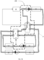
- the battery pack 12 is cooled with the cooler 17, which in this case remains active, following a first hydraulic circuit B, the electric motor 13 is cooled with the radiator 15 following a second hydraulic circuit C, and the passenger compartment 14 is heated with the heater 16 following a third hydraulic circuit A, said three circuits A, B and C being independent of each other.
- the battery pack 12 is cooled with the cooler 17, which in this case also remains active, the electric motor 13 is cooled with the radiator 15 and the cooler 17, and the passenger compartment 14 is heated with the residual heat from the electric motor 13, following a single hydraulic circuit D (highlighted in Figure 7B ).
- the hydraulic circuit D is more complex, in the sense that all the elements to be conditioned, i.e. the battery pack 12, the electric motor 13 and the passenger compartment 14, are in fluidic communication with each other so that it is possible to take advantage of the residual heat of the at least one of these elements (the electric motor 13 in this example) to condition, i.e. to adjust the temperature of at least another of these elements (the passenger compartment 14 in this example), thus improving the energy efficiency of the vehicle.
- Figure 7C shows another of the main operating modes, which is a variant of the hydraulic circuit shown in Figure 7B , represented with circuit E, which could be used in case the residual heat from the electric motor 13 is not sufficient to heat the passenger compartment 14. Therefore, in the example of Figure 7C the battery pack 12 is cooled with the cooler 17, which remains active, and the electric motor 13 is cooled with the radiator 15 and the cooler 17, while the passenger compartment 14 is heated, on the one hand, with the residual heat released by the batteries 12 and the electric motor 13 and, on the other hand, with the heater 16. In this case, because of the residual heat used, the power of the heater 16 required to adjust the temperature of the passenger compartment 14 can be lower.
- the elements to be conditioned i.e.
- the battery pack 12, the electric motor 13 and the passenger compartment 14 are also in fluidic communication with each other so that it is possible to take advantage of the residual heat of at least one of said elements (the electric motor 13 in this example) to help to adjust the temperature of at least another of said elements (the passenger compartment 14 in this example, although the residual heat of the electric motor 13 is not sufficient by itself to adjust the temperature of the passenger compartment 14 as desired).
- the cooler 17 remains inactive, as in the examples shown in Figures 7D and 7E .
- the batteries 12 are heated with the heater 16, following another hydraulic circuit, represented with the letter F, and if the electric motor 13 needs to be cooled, it can be cooled through the radiator 15 following the second hydraulic circuit C, as the one shown in Figure 7A .
- two hydraulic circuits F and C are managed simultaneously. Each hydraulic circuit F and C is used to independently condition a respective element, the battery pack 12 and the electric motor 13 in this case, not being necessary in this case conditioning the passenger compartment 14.
- the cooler 17 is inactive and the batteries 12 and the passenger compartment 14 are heated with the heater 16, following another hydraulic circuit, shown with the letter G, while if it is necessary to cool the electric motor 13 it can be cooled through the radiator 15 following the second hydraulic circuit C, as the one shown in Figure 7A .
- two of the elements to be conditioned are fluidly communicated with each other (the battery pack 12 and the passenger compartment 14) through the hydraulic circuit G, while the third element to be conditioned, the electric motor 13 in this case, is managed independently through the hydraulic circuit C.
- valve assembly 100 or 110 would independently manage the two hydraulic circuits A and C, each valve 1 and 2 of the valve assembly 100 or 110 managing a respective hydraulic circuit, the valve assembly 100 or 110 being operated according to the secondary operation since the connection conduit 5a is blocked.
- a control unit of the vehicle will define the optimum operating mode of the valve assembly 100 or 110 so that the thermal management of the vehicle is the most efficient in each case.
- the vehicle may comprise multiple temperature sensors to assist in monitoring the status of each element to be conditioned, i.e., the battery pack 12, the electric motor 13 and the passenger compartment 14.
- FIGs of Figures 7A to 7F are examples of a few operating modes among the wide variety of modes of operation offered by the valve assembly 100 or 110 of the invention, which as has been demonstrated is achieved with a simple design of the valves 1 and 2, especially with the simple design of the respective valve bodies 3.
- FIGS 7A to 7F show the thermal management module 200 and the valve assembly 100 according to the first embodiment, said diagrams are also valid for any of the described embodiments of the thermal management module and the valve assembly.
Landscapes
- Engineering & Computer Science (AREA)
- General Engineering & Computer Science (AREA)
- Mechanical Engineering (AREA)
- Chemical & Material Sciences (AREA)
- Combustion & Propulsion (AREA)
- Transportation (AREA)
- Multiple-Way Valves (AREA)
Abstract
Valve assembly comprising a first valve (1) and a second valve (2), each valve (1, 2) comprising an inner cavity, a movable valve body (3) arranged inside the inner cavity, and a plurality of conduits (5) in fluidic communication with the respective inner cavity. When rotating the respective valve body (3), at least two of the conduits (5) of the respective valve (1, 2) are fluidically connected. The valve assembly of the invention also comprises a connecting conduit (5a) which fluidically connects the inner cavity of both valves (1, 2), so that the valve bodies (3) can be arranged in such a way that at least one conduit (5) of the first valve (1) is fluidically connected with at least one conduit (5) of the second valve (2). The valve assembly is integrated in a thermal management module comprising a first actuator configured to move the valve body (3) of the first valve (1), and a second actuator configured to move the valve body (3) of the second valve (2), so that each valve body (3) can rotate independently. The thermal management module is assembled in an electric motor vehicle according to the invention.
Description
- The present invention relates to valves and thermal management modules for electric motor vehicles.
- Historically, electric batteries have had high manufacturing costs, weight, long recharge times with short service life and autonomy, which has limited the mass adoption of battery-powered electric vehicles. However, as a result of current technological advantages in batteries and environmental regulations, more and more manufacturers are venturing into electric vehicles instead of conventional combustion vehicles. Therefore, the automotive sector is in a transition phase where the trend is to gradually reduce the production of combustion vehicles and increase the production of electric vehicles.
- Electric vehicles are vehicles that are powered by one or more electric motors, which are powered by electric batteries. These batteries, in order to be efficient, must work within an optimal operating temperature range, so that in some cases it will be necessary to heat the batteries and in others to cool the batteries. Therefore, the thermal management of an electric vehicle is more complex compared to the thermal management of a conventional combustion vehicle, since apart from thermally managing the passenger compartment and the vehicle engine, the batteries must also be thermally managed.
- The space in vehicles to accommodate the necessary elements for good thermal management of the vehicle is limited, being more and more common using integrated modules to facilitate this task. Said modules often include valves that fluidically connect different conduits, each conduit being associated with a vehicle component or element.
- In this regard,
US20150027572A1 describes a six-port valve comprising a main body with an inner cavity, the conduits of the valve being in fluidic communication with the inner cavity. The inner cavity is divided by an insulating wall which divides the inner cavity into two sections. In each section there is a movable valve body that can rotate, so that both valve bodies share an axial shaft that cooperates with an actuator to rotate both valve bodies. Rotating the valve bodies fluidically connects at least two of the six conduits of the valve. - An object of the invention is to provide a valve assembly, as defined in the claims.
- Another object of the invention is to provide an integrated thermal management module for motor vehicles, as defined in the claims.
- The valve assembly of the invention comprises a first valve and a second valve, each valve comprising an inner cavity, a movable valve body arranged inside the inner cavity so that it can rotate, and a plurality of conduits in fluidic communication with the corresponding inner cavity. When rotating the corresponding valve body at least two conduits of the valve assembly are connected fluidically. The valve assembly of the invention also comprises a connecting conduit that fluidically communicates the inner cavity of the first valve and the inner cavity of the second valve, so that the valve bodies of each valve can be arranged in such a way that at least one conduit of the first valve is fluidically connected to at least one conduit of the second valve.
- The integrated thermal management module for motor vehicles of the invention comprises the described valve assembly, a first actuator configured to move the valve body of the first valve, and a second actuator configured to move the valve body of the second valve, so that each valve body can rotate independently.
- Another object of the invention is to provide an electric motor vehicle comprising, elements to be conditioned, conditioning means and the integrated thermal management module of the invention, such that said module is configured to interact with any conditioner of the conditioning means to cool and/or heat any of the elements to be conditioned.
- With the valve assembly of the invention, a higher thermal efficiency of the vehicle where the valve assembly is mounted is achieved in a simple and economical way. The valves of the valve assembly can work independently or jointly through the connection conduit, thus increasing the number of active conduits of the valve assembly in a simple way, which allows to increase the number of possible combinations to connect the different conduits of the valve assembly, that is to say, it allows to design a great variety of operating modes of the valve assembly, without complicating the design of the valve bodies to achieve this purpose, obtaining, due to the invention, a compact, reliable and economical valve assembly. Thus, it is possible to manage the elements to be conditioned of the vehicle of the invention through the module of the invention in an independent manner, that is to say, without them being fluidly communicated with each other, or in a dependent manner, that is to say, in such a way that at least two of the elements to be conditioned are fluidly communicated with each other, so that it is possible to take advantage of the residual heat of one of the elements to be conditioned to thermally conditioning another element of the elements to be conditioned, i.e. to adjust the temperature of this element, thus improving the energy efficiency of the vehicle.
- Also, as the valve assembly is integrated into a module, it facilitates its assembly in the vehicle, achieving a significant saving of space and parts in the vehicle, as the route of the hoses or tubes of the vehicle's hydraulic circuits is optimised.
- These and other advantages and features of the invention will become apparent in view of the figures and the detailed description of the invention.
-
-
Figure 1 shows a perspective view of a first embodiment of the integrated thermal management module comprising a first embodiment of the valve assembly of the invention. -
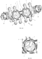
Figure 2A shows a sectional perspective view of the module ofFigure 1 . -
Figure 2B shows a detail ofFigure 2A . -
Figure 3 shows a perspective view of a first embodiment of the valve assembly according to the invention, which is integrated in the module offigure 1 , the first valve and the second valve being without the corresponding closing cap. -
Figure 4 shows another perspective view of the valve assembly ofFigure 3 but without the valve bodies. -
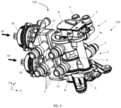
Figure 5 shows a perspective view of a second embodiment of the module of the invention comprising a second embodiment of the valve assembly of the invention. -
Figure 6 shows a sectional view of the valve assembly of the module ofFigure 5 . -
Figure 7 shows a schematic representation of the elements to be conditioned, the conditioning means and the integrated thermal management module of the electric motor vehicle of the invention. -
Figures 7A to 7F show different hydraulic circuits representing different operation modes of the integrated thermal management module of the invention. - With electric vehicles, the thermal management of vehicles has become more complicated, because it is not sufficient to have a cooling circuit that cools the combustion engine or the passenger compartment of the vehicle, and/or a heating system that heats the passenger compartment of the vehicle, for example. With the electric vehicle, it is also necessary to cool or to heat the batteries of the electric vehicle.
- The integrated module of the invention, which incorporates the valve assembly of the invention, allows the thermal efficiency of the vehicle to be improved, as will be detailed throughout the description.
-
Figure 1 shows a perspective view of a first embodiment of the integratedmodule 200 of the invention comprising a first embodiment of thevalve assembly 100 according to a first embodiment of the invention. - The valve assembly of the invention comprises a
first valve 1 and asecond valve 2, as shown in the non-limiting example ofFigure 1 . Eachvalve inner cavity 4, shown inFigure 4 , amovable valve body 3 arranged inside saidinner cavity 4 so that it can rotate, as can be seen in the non-limiting example ofFigure 3 , and a plurality ofconduits 5 in fluidic communication with the correspondinginner cavity 4, as can be seen for example inFigure 2A . When acorresponding valve body 3 is rotated, at least two of theconduits 5 of the valve assembly are fluidically connected. The valve assembly of the invention also comprises a connectingconduit 5a which fluidically communicates theinner cavity 4 of thefirst valve 1 and theinner cavity 4 of thesecond valve 2, so that thevalve bodies 3 of eachvalve conduit 5 of thefirst valve 1 is fluidically connected with at least oneconduit 5 of thesecond valve 2, allowing the fluid of a corresponding hydraulic circuit of the vehicle's thermal system to be directed from theconduit 5 of thefirst valve 1 to theconduit 5 of thesecond valve 2, or vice versa. - With the valve assembly of the invention it is possible to improve the thermal efficiency of the vehicle in which the valve assembly is mounted in a simple and economical manner. The
valves valve assembly 100 can work independently or jointly through the connectingconduit 5a, thus allowing to increase the number ofactive conduits 5 of thevalve assembly 100, i.e. conduits carrying a fluid, in a simple manner, and also allowing to increase the number of possible combinations for connecting theconduits 5 of thevalve assembly 100 to each other, what makes it possible to design a wide variety of operating modes of thevalve assembly 100, as will be detailed further below, without complicating the design of thevalve bodies 3 for this purpose, thus obtaining, thanks to the invention, a reliable and economicalcompact valve assembly 100. -
Figure 3 shows a first embodiment of thevalve assembly 100 andFigure 4 shows saidvalve assembly 100 but without thevalve bodies 3 to better appreciate theinner cavity 4 of eachvalve valve assembly 100 comprises amain body 6, saidmain body 6 comprising the twoinner cavities 4 such that bothinner cavities 4 are fluidically communicated through the connectingconduit 5a, as shown inFigure 4 . Eachvalve body 3 is arranged in a respectiveinner cavity 4, as shown infigure 3 . In order to make theinner cavity 4 of eachvalve valve closing cap 11 which is fitted after thecorresponding valve body 3 has been assembled. For a better understanding of the invention, inFigure 3 theclosing caps 11 are not shown. - In the non-limiting example of the
valve assembly 100 shown inFigure 3 , theinner cavities 4 of the twovalves conduit 5a is arranged between the twoinner cavities 4, preferably also in the longitudinal direction X. - In the non-limiting example of the
valve assembly 100 shown inFigure 3 , theclosing caps 11 of eachinner cavity 4 are joined together forming a single part, thus ensuring a tight seal, not only of eachinner cavity 4 but also of the connectingconduit 5a. - In another embodiment of the
valve assembly 110 of the invention shown inFigures 5 and6 , theinner cavities 4 of the twovalves conduit 5a is preferably arranged on one side of themain body 6 of thevalve assembly 110, in the axial direction Z, but could also be arranged, for example, in said axial direction Z but between the two correspondinginner cavities 4. - Each
valve shaft 7 cooperating with thecorresponding valve body 3, eachshaft 7 being configured to couple to arespective actuator 8, so that thecorresponding valve body 3 can rotate. The twoshafts 7 of the invention are not coupled to each other, so that eachvalve body 3 can rotate independently of each other. Preferably, eachvalve body 3 and therespective shaft 7 form a single part, saidshaft 7 protruding axially from thevalve body 3 in the Z direction, in any of the described embodiments. - The integrated
thermal management module 200 offigure 1 comprising thevalve assembly 100 offigure 3 , also comprises afirst actuator 8 configured to move thevalve body 3 of thefirst valve 1 and asecond actuator 8 configured to move thevalve body 3 of thesecond valve 2. Theshaft 7 of eachvalve respective actuator 8, as shown inFigure 1 orFigure 5 , so that thanks to eachactuator 8, thevalve bodies 3 of eachvalve - The
module 200 also comprises a firsthydraulic pump 10 which is in fluidic communication with at least oneconduit 5 communicated with theinner cavity 4 of thefirst valve 1, and a secondhydraulic pump 10 which is in fluidic communication with at least oneconduit 5 communicated with theinner cavity 4 of thesecond valve 2, as shown in the diagram ofFigure 7 . - In the non-limiting example of
module 200 ofFigure 1 , thehydraulic pumps 10 and therespective valves valve assembly 100 ofFigure 3 are arranged next to each other in the longitudinal direction X, each pump 10 being arranged at one end of thevalve assembly 100, following the horizontal arrangement. - In the embodiment of the integrated
thermal management module 210 ofFigure 5 , comprising thevalve assembly 110 ofFigure 6 and also comprising arespective actuator 8 configured to move thevalve body 3 of thecorresponding valve valve body 3 can rotate independently of each other, it also comprises a respectivehydraulic pump 10 in fluidic communication with at least oneconduit 5 communicated with theinner cavity 4 of thecorresponding valve hydraulic pump 10 and thefirst valve 1 are arranged according to a first longitudinal direction X1 at a first level, and the secondhydraulic pump 10 and thesecond valve 2 are arranged according to a second longitudinal direction X2 parallel to the first longitudinal direction X1, so that therespective valves valve assembly 110 ofFigure 6 . - In any of the embodiments of the
valve assembly inner cavity 4 of eachvalve conduits 5 and with the connectingconduit 5a, therespective valve body 3 being configured to selectively communicate at least two of saidconduits 5 during use, so that thevalve assembly conduits 5 of thevalve assembly valve assembly - As shown in the non-limiting example of
Figure 2B , thevalve body 3 of eachvalve invention passage channels 9, saidpassage channels 9 being configured to allow the passage of a fluid between twoconduits 5 of arespective valve conduit 5 of therespective valve conduit 5a. - Thus, the valve assembly of the
invention valve bodies 3 of thevalves first conduit 5 of thefirst valve 1 is fluidically connected to afirst conduit 5 of thesecond valve 2, asecond conduit 5 of thefirst valve 1 can be fluidically connected to athird conduit 5 of thefirst valve 1, and asecond conduit 5 of thesecond valve 2 can be fluidically connected to athird conduit 5 of thesecond valve 2, whereby thevalve assembly Figures 7A to 7E . - Likewise, the valve assembly of the
invention valve bodies 3 of thevalves conduits 5 of thefirst valve 1 are fluidically connected to each other, and/or at least twoconduits 5 of thesecond valve 2 can be fluidically connected to each other, thus being able to manage simultaneously up to two independent hydraulic circuits for eachvalve Figure 7F . - The electric motor vehicle of the invention comprises elements to be conditioned comprising a first element, preferably a
battery pack 12, a second element, preferably at least one electric motor 13 (preferably with its corresponding power electronics, such as for example a power inverter), said at least oneelectric motor 13 being powered by thebattery pack 12, and a third element, preferably apassenger compartment 14 where the passengers of the vehicle are accommodated, preferably seated, although the passengers could also stand in thepassenger compartment 14, for example if the vehicle is a bus. The vehicle also comprises at least threehydraulic pumps 10, thebattery pack 12, theelectric motor 13 and thepassenger compartment 14 being able to be associated with a respectivehydraulic pump 10 which facilitates the circulation of a coolant, for example glycol, as shown for example in the example ofFigure 7A , or at least two of the elements to be conditioned 12, 13 or 14 being able to be associated with the samehydraulic pump 10. Two of saidhydraulic pumps 10 and thevalve assembly thermal management module module - In some cases it will be necessary to heat the
battery pack 12, and in other cases it will be necessary to cool thebattery pack 12, so that thebattery pack 12 can operate in an optimal operating temperature range. In some cases, it will also be necessary to heat thepassenger compartment 14, and in other cases to cool theelectric motor 13. - The vehicle of the invention also comprises conditioning means for thermally conditioning the elements to be conditioned 12, 13 and 14, i.e., for heating or cooling them. The conditioning means comprise a first conditioner, preferably a
radiator 15, a second conditioner, preferably aheater 16, and a third conditioner, preferably a cooler 17, themodule radiator 15, theheater 16 and/or the cooler 17 to cool or heat thebattery pack 12, theelectric motor 13 and/or thepassenger compartment 14. - Each
conduit 5 of thevalve assembly respective conditioning element respective conditioner hydraulic pump 10, as shown inFigure 7 . -
Figure 7 shows a schematic representation of the elements to be conditioned 12, 13 and 14, the conditioning means 15, 16 and 17, thehydraulic pumps 10 and the integratedthermal management module 200 of the electric motor vehicle of the invention. As can be seen in said figure, two of thepumps 10 are integrated in themodule 200 of the invention, thepumps 10 being in fluidic communication with aconduit 5 communicated with theinner cavity 4 of arespective valve - As already discussed, the
module valve assembly battery pack 12, theelectric motor 13 and thepassenger compartment 14 via theradiator 15, theheater 16 and/or the cooler 17, as shown in the example ofFigure 7A . - However, thanks to the
valve assembly valve body 3 which is difficult to manufacture, thus improving the thermal efficiency of the vehicle, being possible to design a plurality of operating modes of thevalve assembly - Thus, with the
module respective conditioner valve assembly Figures 7A ,7D or7F and which will be detailed below, wherein the elements to be conditioned 12, 13 and 14 are not in fluidic communication with each other, it being possible to manage all the hydraulic circuits simultaneously in an independent manner. However, on the other hand, it is also possible to thermally conditioning each element to be conditioned 12, 13, or 14 by any of theconditioners Figures 7B ,7C or7E and which will be detailed below. In this case, at least two of the elements to be conditioned 12, 13 or 14 are fluidly communicated with each other through a respective hydraulic circuit which is also managed by thevalve assembly - In the example of
Figure 7A , where one of the main operating modes is shown, thebattery pack 12 is cooled with the cooler 17, which in this case remains active, following a first hydraulic circuit B, theelectric motor 13 is cooled with theradiator 15 following a second hydraulic circuit C, and thepassenger compartment 14 is heated with theheater 16 following a third hydraulic circuit A, said three circuits A, B and C being independent of each other. However, in the example ofFigure 7B , where another of the main operating modes is shown, thebattery pack 12 is cooled with the cooler 17, which in this case also remains active, theelectric motor 13 is cooled with theradiator 15 and the cooler 17, and thepassenger compartment 14 is heated with the residual heat from theelectric motor 13, following a single hydraulic circuit D (highlighted inFigure 7B ). In this case, the hydraulic circuit D is more complex, in the sense that all the elements to be conditioned, i.e. thebattery pack 12, theelectric motor 13 and thepassenger compartment 14, are in fluidic communication with each other so that it is possible to take advantage of the residual heat of the at least one of these elements (theelectric motor 13 in this example) to condition, i.e. to adjust the temperature of at least another of these elements (thepassenger compartment 14 in this example), thus improving the energy efficiency of the vehicle. -
Figure 7C shows another of the main operating modes, which is a variant of the hydraulic circuit shown inFigure 7B , represented with circuit E, which could be used in case the residual heat from theelectric motor 13 is not sufficient to heat thepassenger compartment 14. Therefore, in the example ofFigure 7C thebattery pack 12 is cooled with the cooler 17, which remains active, and theelectric motor 13 is cooled with theradiator 15 and the cooler 17, while thepassenger compartment 14 is heated, on the one hand, with the residual heat released by thebatteries 12 and theelectric motor 13 and, on the other hand, with theheater 16. In this case, because of the residual heat used, the power of theheater 16 required to adjust the temperature of thepassenger compartment 14 can be lower. In this example, the elements to be conditioned, i.e. thebattery pack 12, theelectric motor 13 and thepassenger compartment 14, are also in fluidic communication with each other so that it is possible to take advantage of the residual heat of at least one of said elements (theelectric motor 13 in this example) to help to adjust the temperature of at least another of said elements (thepassenger compartment 14 in this example, although the residual heat of theelectric motor 13 is not sufficient by itself to adjust the temperature of thepassenger compartment 14 as desired). - If the
batteries 12 need to be heated, the cooler 17 remains inactive, as in the examples shown inFigures 7D and7E . In the operating mode represented infigure 7D , which is also a main operating mode, thebatteries 12 are heated with theheater 16, following another hydraulic circuit, represented with the letter F, and if theelectric motor 13 needs to be cooled, it can be cooled through theradiator 15 following the second hydraulic circuit C, as the one shown inFigure 7A . Thus, in the example offigure 7D , two hydraulic circuits F and C are managed simultaneously. Each hydraulic circuit F and C is used to independently condition a respective element, thebattery pack 12 and theelectric motor 13 in this case, not being necessary in this case conditioning thepassenger compartment 14. - In the operating mode shown in
figure 7E , which is also a main operating mode, the cooler 17 is inactive and thebatteries 12 and thepassenger compartment 14 are heated with theheater 16, following another hydraulic circuit, shown with the letter G, while if it is necessary to cool theelectric motor 13 it can be cooled through theradiator 15 following the second hydraulic circuit C, as the one shown inFigure 7A . In this case, therefore, two of the elements to be conditioned are fluidly communicated with each other (thebattery pack 12 and the passenger compartment 14) through the hydraulic circuit G, while the third element to be conditioned, theelectric motor 13 in this case, is managed independently through the hydraulic circuit C. - If it was only necessary to heat the
passenger compartment 14, for example, the passage of the fluid towards theconnection conduit 5a could be blocked to work with one of thevalves Figure 7F , where one of the secondary operating modes is shown, thepassenger compartment 14 is heated with theheater 16, following the third hydraulic circuit A, as the one shown inFigure 7A , no further hydraulic circuit being necessary. However, if it is also necessary to condition theelectric motor 13 for example, it could be cooled through theradiator 15 via the second hydraulic circuit C, as the one shown infigures 7A or7D . In the latter case, thevalve assembly valve valve assembly valve assembly connection conduit 5a is blocked. - Therefore, depending on the thermal needs of each element to be conditioned of the vehicle, which will be influenced in part by the environment in which the vehicle is driven, a control unit of the vehicle, not shown in the drawings, will define the optimum operating mode of the
valve assembly battery pack 12, theelectric motor 13 and thepassenger compartment 14. - The diagrams of
Figures 7A to 7F are examples of a few operating modes among the wide variety of modes of operation offered by thevalve assembly valves respective valve bodies 3. - Although
Figures 7A to 7F show thethermal management module 200 and thevalve assembly 100 according to the first embodiment, said diagrams are also valid for any of the described embodiments of the thermal management module and the valve assembly.
Claims (15)
- Valve assembly comprising a first valve (1) and a second valve (2), each valve (1, 2) comprising an inner cavity (4), a movable valve body (3) arranged inside the inner cavity (4) so that it can rotate, and a plurality of conduits (5) in fluidic communication with the corresponding inner cavity (4), so that rotating the valve body (3) at least two of the conduits (5) of the valve assembly (100; 110) are fluidically connected, characterized in that the valve assembly (100; 110') comprises a connecting conduit (5a) which fluidically connects the inner cavity (4) of the first valve (1) and the inner cavity (4) of the second valve (2), so that the valve bodies (3) of each valve (1, 2) can be arranged in such a way that at least one conduit (5) of the first valve (1) is fluidically connected to at least one conduit (5) of the second valve (2).
- Valve assembly according to claim 1, wherein the valve assembly (100; 110) comprises a main body (6), said main body (6) comprising the two inner cavities (4), so that both inner cavities (4) are fluidically connected through the connecting conduit (5a), a respective valve body (3) being provided in each inner cavity (4) .
- Valve assembly according to claim 1 or 2, wherein each valve (1, 2) also comprises a shaft (7) cooperating with the respective valve body (3), each shaft (7) being configured to couple to a respective actuator (8), so that the respective valve body (3) can rotate.
- Valve assembly according to claim 3, wherein each valve body (3) and the respective shaft (7) form a single part, said shaft (7) protruding axially from the valve body (3).
- Valve assembly according to any one of the preceding claims, wherein the inner cavity (4) of each valve (1, 2) is in fluidic communication with four conduits (5) and with the connecting conduit (5a), the respective valve body (3) being configured to selectively communicate at least two of said conduits (5), so that the valve assembly (100; 110) can work as two independent four-way valves or as an eight-way valve.
- Valve assembly according to claim 5, wherein the valve body (3) of each valve (1, 2) comprises three passage channels (9), the passage channels (9) being configured to allow the passage of a fluid between two conduits (5) of a respective valve (1, 2), or between a conduit (5) of the respective valve (1, 2) and the connecting conduit (5a).
- Valve assembly according to claim 5 or 6, wherein the valve assembly (100; 110) comprises a main operating mode wherein the valve bodies (3) of the valves (1, 2) are arranged in such a way that a first conduit (5) of the first valve (1) is fluidically connected to a first conduit (5) of the second valve (2), a second conduit (5) of the first valve (1) is fluidically connected to a third conduit (5) of the first valve (1), and a second conduit (5) of the second valve (2) is fluidically connected to a third conduit (5) of the second valve (2), so that up to three independent hydraulic circuits can be managed simultaneously.
- Valve assembly according to any one of claims 5 to 7, wherein the valve assembly (100; 110) comprises a secondary operating mode wherein the valve bodies (3) of the valves (1, 2) are arranged in such a way that at least two conduits (5) of the first valve (1) are fluidically connected to each other, and/or at least two conduits (5) of the second valve (2) are fluidically connected to each other, so that up to two independent hydraulic circuits per valve (1, 2) can be managed simultaneously.
- Integrated thermal management module for motor vehicles, characterized in that it comprises a valve assembly (100; 110) according to any of the preceding claims, a first actuator (8) configured to move the valve body (3) of the first valve (1), and a second actuator (8) configured to move the valve body (3) of the second valve (2).
- Integrated thermal management module according to claim 9, comprising a first hydraulic pump (10) in fluidic communication with a conduit (5) connected to the inner cavity (4) of the first valve (1), and a second hydraulic pump (10) in fluidic communication with a conduit (5) connected to the inner cavity (4) of the second valve (2).
- Integrated thermal management module according to claim 10, wherein the hydraulic pumps (10) and the respective valves (1, 2) of the valve assembly (100) are arranged one after the other in a longitudinal direction (X), each pump (10) being arranged at one end of the valve assembly (100).
- Integrated thermal management module according to claim 10, wherein the first hydraulic pump (10) and the first valve (1) are arranged according to a first longitudinal direction (X1) on a first level, and the second hydraulic pump (10) and the second valve (2) are arranged according to a second longitudinal direction (X2) parallel to the first longitudinal direction (X1) on a second level, so that the respective valves (1, 2) are arranged according to an axial direction (Z) perpendicular to the longitudinal direction (X).
- Electric motor vehicle comprising elements to be conditioned comprising a first element (12), preferably a battery pack, a second element (13), preferably an electric motor, and a third element (14), preferably a passenger compartment where the passengers of the vehicle are located, and the vehicle also comprising conditioning means comprising a first conditioner (15), preferably a radiator, a second conditioner (16), preferably a heater, and a third conditioner (17), preferably a cooler, and at least three hydraulic pumps (10), characterized in that two of the hydraulic pumps (10) are integrated in an integrated thermal management module (200; 210) according to any of claims 9 to 12, said module (200; 210) being configured to interact with any of the conditioning means (15, 16, 17) to cool and/or heat any of the elements to be conditioned (12, 13, 14).
- Method of thermal management of the electric motor vehicle according to claim 13, wherein each conditioning element (12, 13, 14) can be conditioned by any of the conditioners (15, 16, 17) of the conditioning means and/or by another conditioning element (12, 13) via a respective hydraulic circuit which is managed by the valve assembly (100; 110) according to any of claims 1 to 8.
- Method for thermal management of the electric motor vehicle according to claim 13, wherein each element to be conditioned (12, 13, 14) can be conditioned by a respective conditioner (15, 16, 17) of the conditioning means via a respective hydraulic circuit which is managed by the valve assembly (100; 110) according to any of claims 1 to 8.
Priority Applications (1)
| Application Number | Priority Date | Filing Date | Title |
|---|---|---|---|
| EP23382378.0A EP4450853A1 (en) | 2023-04-21 | 2023-04-21 | Valve assembly, integrated thermal management module and electric motor vehicle |
Applications Claiming Priority (1)
| Application Number | Priority Date | Filing Date | Title |
|---|---|---|---|
| EP23382378.0A EP4450853A1 (en) | 2023-04-21 | 2023-04-21 | Valve assembly, integrated thermal management module and electric motor vehicle |
Publications (1)
| Publication Number | Publication Date |
|---|---|
| EP4450853A1 true EP4450853A1 (en) | 2024-10-23 |
Family
ID=86330054
Family Applications (1)
| Application Number | Title | Priority Date | Filing Date |
|---|---|---|---|
| EP23382378.0A Withdrawn EP4450853A1 (en) | 2023-04-21 | 2023-04-21 | Valve assembly, integrated thermal management module and electric motor vehicle |
Country Status (1)
| Country | Link |
|---|---|
| EP (1) | EP4450853A1 (en) |
Cited By (1)
| Publication number | Priority date | Publication date | Assignee | Title |
|---|---|---|---|---|
| DE102024209400A1 (en) * | 2024-09-27 | 2026-04-02 | Zf Friedrichshafen Ag | Distribution unit |
Citations (8)
| Publication number | Priority date | Publication date | Assignee | Title |
|---|---|---|---|---|
| US20150027572A1 (en) | 2013-07-25 | 2015-01-29 | Schaeffler Technologies Gmbh & Co. Kg | Thermal management valve module with isolated flow chambers |
| DE102018102542A1 (en) * | 2018-01-29 | 2019-08-01 | Woco Industrietechnik Gmbh | Apparatus for handling fluids and method for producing the same |
| DE102021000262A1 (en) * | 2020-01-30 | 2021-08-05 | Voss Automotive Gmbh | Mass flow control device |
| CN114382919A (en) * | 2020-10-22 | 2022-04-22 | 本田技研工业株式会社 | Flow path switching valve |
| CN115247719A (en) * | 2021-04-26 | 2022-10-28 | 龙泉市惠丰进出口有限公司 | 5/5-way valve |
| US11506306B2 (en) * | 2019-09-17 | 2022-11-22 | Ford Global Technologies, Llc | Thermal management system for electrified vehicle |
| FR3123703A1 (en) * | 2021-06-04 | 2022-12-09 | Psa Automobiles Sa | VEHICLE COOLANT DISTRIBUTION SYSTEM |
| CN218152494U (en) * | 2022-05-25 | 2022-12-27 | 南方英特空调有限公司 | Multi-ported valve structure with multi-proportion regulation for automobile thermal management system |
-
2023
- 2023-04-21 EP EP23382378.0A patent/EP4450853A1/en not_active Withdrawn
Patent Citations (8)
| Publication number | Priority date | Publication date | Assignee | Title |
|---|---|---|---|---|
| US20150027572A1 (en) | 2013-07-25 | 2015-01-29 | Schaeffler Technologies Gmbh & Co. Kg | Thermal management valve module with isolated flow chambers |
| DE102018102542A1 (en) * | 2018-01-29 | 2019-08-01 | Woco Industrietechnik Gmbh | Apparatus for handling fluids and method for producing the same |
| US11506306B2 (en) * | 2019-09-17 | 2022-11-22 | Ford Global Technologies, Llc | Thermal management system for electrified vehicle |
| DE102021000262A1 (en) * | 2020-01-30 | 2021-08-05 | Voss Automotive Gmbh | Mass flow control device |
| CN114382919A (en) * | 2020-10-22 | 2022-04-22 | 本田技研工业株式会社 | Flow path switching valve |
| CN115247719A (en) * | 2021-04-26 | 2022-10-28 | 龙泉市惠丰进出口有限公司 | 5/5-way valve |
| FR3123703A1 (en) * | 2021-06-04 | 2022-12-09 | Psa Automobiles Sa | VEHICLE COOLANT DISTRIBUTION SYSTEM |
| CN218152494U (en) * | 2022-05-25 | 2022-12-27 | 南方英特空调有限公司 | Multi-ported valve structure with multi-proportion regulation for automobile thermal management system |
Cited By (1)
| Publication number | Priority date | Publication date | Assignee | Title |
|---|---|---|---|---|
| DE102024209400A1 (en) * | 2024-09-27 | 2026-04-02 | Zf Friedrichshafen Ag | Distribution unit |
Similar Documents
| Publication | Publication Date | Title |
|---|---|---|
| US11821526B2 (en) | Apparatus for handling fluid within an at least partially electrically driven vehicle | |
| US10807441B2 (en) | Drive train for a vehicle | |
| EP3936709B1 (en) | A component housing unit and a vehicle thermal management system comprising a component housing unit | |
| US10717367B1 (en) | Thermal control systems for battery charging | |
| US20250220865A1 (en) | Cooling module | |
| US11264656B2 (en) | Control module for the temperature control of a battery | |
| US11221076B2 (en) | Device for regulating a flow-through and distributing a fluid in a fluid circuit | |
| EP3720732B1 (en) | A coolant system for a vehicle | |
| EP4450853A1 (en) | Valve assembly, integrated thermal management module and electric motor vehicle | |
| US20250018786A1 (en) | Coolant system for an electric vehicle, and thermal management system | |
| KR20210061158A (en) | Integrated Thermal Management Valve For Vehicle | |
| KR20210061520A (en) | Integrated Thermal Management Valve For Vehicle | |
| KR102869242B1 (en) | Valve for switching the coolant | |
| US12486910B2 (en) | Eight-way valve | |
| EP3549799B1 (en) | A vehicle thermal management system | |
| EP4282672B1 (en) | Electric vehicle thermal management system and vehicle | |
| US20230083635A1 (en) | Drive device with self-controlled cooling | |
| KR20250068389A (en) | Vehicular thermal management system | |
| US20250026172A1 (en) | Switching device and thermal management system | |
| CN223904831U (en) | Heat management devices and heat management systems | |
| EP4414589A1 (en) | A valve assembly for thermal management systems in vehicles | |
| CN112583206A (en) | Cooling duct arrangement for driving an electric machine, electric machine and motor vehicle | |
| US20260112741A1 (en) | Thermal management system for electrified vehicle | |
| KR20260026675A (en) | Multi-way valve apparatus | |
| CN120513177A (en) | Pre-integrated oil cooling module and vehicle |
Legal Events
| Date | Code | Title | Description |
|---|---|---|---|
| PUAI | Public reference made under article 153(3) epc to a published international application that has entered the european phase |
Free format text: ORIGINAL CODE: 0009012 |
|
| STAA | Information on the status of an ep patent application or granted ep patent |
Free format text: STATUS: THE APPLICATION HAS BEEN PUBLISHED |
|
| AK | Designated contracting states |
Kind code of ref document: A1 Designated state(s): AL AT BE BG CH CY CZ DE DK EE ES FI FR GB GR HR HU IE IS IT LI LT LU LV MC ME MK MT NL NO PL PT RO RS SE SI SK SM TR |
|
| STAA | Information on the status of an ep patent application or granted ep patent |
Free format text: STATUS: THE APPLICATION IS DEEMED TO BE WITHDRAWN |
|
| 18D | Application deemed to be withdrawn |
Effective date: 20250424 |