EP4450847A1 - Vibration control system, vehicle, structure, and method - Google Patents
Vibration control system, vehicle, structure, and method Download PDFInfo
- Publication number
- EP4450847A1 EP4450847A1 EP23275066.1A EP23275066A EP4450847A1 EP 4450847 A1 EP4450847 A1 EP 4450847A1 EP 23275066 A EP23275066 A EP 23275066A EP 4450847 A1 EP4450847 A1 EP 4450847A1
- Authority
- EP
- European Patent Office
- Prior art keywords
- vibration
- resonator arrangement
- control system
- resonator
- vibration control
- Prior art date
- Legal status (The legal status is an assumption and is not a legal conclusion. Google has not performed a legal analysis and makes no representation as to the accuracy of the status listed.)
- Ceased
Links
- 238000000034 method Methods 0.000 title claims description 9
- 238000013459 approach Methods 0.000 description 19
- 230000003044 adaptive effect Effects 0.000 description 6
- 238000010408 sweeping Methods 0.000 description 2
- 238000010521 absorption reaction Methods 0.000 description 1
- 230000002411 adverse Effects 0.000 description 1
- 239000000470 constituent Substances 0.000 description 1
- 238000013016 damping Methods 0.000 description 1
- 230000000694 effects Effects 0.000 description 1
- 238000011835 investigation Methods 0.000 description 1
Images

Classifications
-
- F—MECHANICAL ENGINEERING; LIGHTING; HEATING; WEAPONS; BLASTING
- F16—ENGINEERING ELEMENTS AND UNITS; GENERAL MEASURES FOR PRODUCING AND MAINTAINING EFFECTIVE FUNCTIONING OF MACHINES OR INSTALLATIONS; THERMAL INSULATION IN GENERAL
- F16F—SPRINGS; SHOCK-ABSORBERS; MEANS FOR DAMPING VIBRATION
- F16F15/00—Suppression of vibrations in systems; Means or arrangements for avoiding or reducing out-of-balance forces, e.g. due to motion
- F16F15/002—Suppression of vibrations in systems; Means or arrangements for avoiding or reducing out-of-balance forces, e.g. due to motion characterised by the control method or circuitry
-
- G—PHYSICS
- G05—CONTROLLING; REGULATING
- G05D—SYSTEMS FOR CONTROLLING OR REGULATING NON-ELECTRIC VARIABLES
- G05D19/00—Control of mechanical oscillations, e.g. of amplitude, of frequency, of phase
- G05D19/02—Control of mechanical oscillations, e.g. of amplitude, of frequency, of phase characterised by the use of electric means
Definitions
- the present invention relates to a vibration control system.
- the present invention further relates to a vehicle or structure comprising a vibration control system.
- the present invention further relates to a method of controlling vibration.
- the vibrations of heavy machinery, for example engines, during their operation can have an adverse effect on the bodies or structures on which said machinery is mounted.
- the vibration of an engine mounted in vehicles including aircraft, watercraft and land-going vehicles can impact vehicle efficiency, accuracy of instrumentation, vehicle noise, and stability.
- Vibration control systems are desirable in many settings in order to mitigate the impact of the vibration.
- Known vibration control systems employ resonator arrangements to control vibration of a structure by absorbing energy therefrom.
- the tuning of the resonator arrangement may be swept across a frequency band to control frequency responses of vibrations of a structure within said band.
- actual frequency response of vibrations of the structure are not considered during the sweeping of the tuning of the resonator arrangement.
- a vibration control system for controlling vibration of a structure
- the vibration control system comprising: a resonator arrangement for controlling vibration of the structure by absorbing energy therefrom, the resonator arrangement being tunable to tune one or more resonance frequencies of the resonator arrangement; and a controller configured to: determine a frequency response of vibration of the structure; tune the one or more resonance frequencies of the resonator arrangement based on the determined frequency response of vibration of the structure; and control vibration of the structure by operating the tuned resonator arrangement.
- the resonator arrangement comprises one or more shunted electromechanical transducers.
- shunt impedances are analogue.
- the controller is configured to: determine the frequency response of vibration of the structure; tune the one or more resonance frequencies of the resonator arrangement to a tuning corresponding to specific frequencies of vibration of the structure; and repeat the preceding steps.
- the controller is configured to: periodically update the tuning of the resonator arrangement.
- the specific frequencies of vibration of the structure frequency of vibration of the structure are frequencies of highest magnitude of vibration of the structure.
- the controller is configured to distribute the resonance frequencies of the resonator arrangement around one or more frequencies of highest magnitude of vibration of the structure.
- the resonator arrangement comprises one or more single degree of freedom actuators.
- the resonator arrangement comprises one or more multiple degree of freedom actuators.
- the resonator arrangement comprises one or more electromechanical actuators.
- a vehicle or structure comprising the vibration control system according to the first aspect of the present invention.
- the second aspect of the present invention may incorporate any or all of the features of the first aspect of the present invention, as desired or as appropriate.
- a method of controlling vibration of a structure using a resonator arrangement for controlling vibration of the structure by absorbing energy therefrom, the resonator arrangement being tunable to tune one or more resonance frequencies of the resonator arrangement comprising: determining a frequency response of vibration of the structure; tuning one or more resonance frequencies of the resonator arrangement based on the determined frequency response of vibration of the structure; and controlling vibration of the structure by operating the tuned resonator arrangement.
- a vibration control system is described herein.
- An important feature of the present invention is that a resonator arrangement is tuned based on a determined frequency response of vibration of a structure. This may be known as an "adaptive tuning" approach, where the tuning is adapted based on the determined frequency response of vibration of the structure.
- a key benefit of the present approach is the ability to adapt to the modal frequencies of the structure. Vibration of the structure may result in a frequency response, or profile, having one or more peak frequencies which it is desired to control.
- Prior art approaches seek to sweep tuning of a resonator arrangement without considering the frequency response of vibration of the structure to be controlled. That is, prior art approaches do not incorporate adaptive tuning. Further detail will be provided herein.
- the frequency response of vibration of the structure is an investigation of the vibration of the structure in the frequency domain. This enables the determination of frequency components which are prominent, or dominant, in the vibration of the structure. These frequency components may be related to fundamental movements of the structure, which may relate to the nature of the structure (e.g., its constituent parts or arrangement of parts).
- the tuning is based on the determined frequency response of vibration of the structure. Furthermore, tuning may be switched (e.g., abruptly, or discontinuously, changed) to control different frequencies of vibration, rather than swept (e.g., continuously changed) as in prior art approaches.
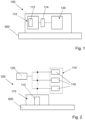
- the vibration control system 100 is for controlling vibration of a structure 500.
- the vibration control system 100 comprises a resonator arrangement 110.
- the resonator arrangement 110 is for controlling vibration of the structure 500 by absorbing energy therefrom.
- the resonator arrangement 110 is tunable to tune one or more resonance frequencies of the resonator arrangement 110.
- the vibration control system 100 comprises a controller 120.
- the controller 120 is configured to determine a frequency response of vibration of the structure 500.
- the controller 120 is configured to tune the one or more resonance frequencies of the resonator arrangement 110 based on the determined frequency response of vibration of the structure 500. That is, tuning of the resonator arrangement 110 is based on the determined frequency response of vibration of the structure 500.
- the controller 120 is configured to control the vibration of the structure 500 by operating the tuned resonator arrangement 110.
- the present vibration control system 100 is easier and cheaper to implement using analogue circuitry when compared with a sweep approach. Despite the difference in approach, comparable performance (i.e., level of control of vibration of the structure) is achieved.
- vibration control system 100 Further detail on the vibration control system 100 will be provided below.
- the resonance frequency of the resonator arrangement 110 can be tuned using shunt impedance.
- shunt impedance By tuning the resonator arrangement 110 using shunt impedance in consideration of, or based on, the frequency response of vibration of the structure 500, targeted vibration control of vibrations of the structure 500 can be provided.
- use of shunt circuits causes electrical current to be distributed between the shunt circuit and the resonator arrangement 110. In this way, the current provided to resonators of the resonator arrangement 110 can be altered, thereby to change (or "tune") the resonance frequency of the resonator arrangement 110.
- the amount of electrical current distributed between the shunt circuit and the resonator arrangement 110 depends on the value of the shunt impedance of the shunt circuit.
- the value of the shunt impedance of the shunt circuit is a function of resistance, inductance, and capacitance of the shunt circuit (e.g., of components of the shunt circuit).
- the resonance frequency of the resonator arrangement may correspond with a resonance frequency of one or more resonators of the resonator arrangement 110, or of the resonator arrangement 110 as a whole.
- the vibration control system 100 may be provided in a metamaterial.
- the metamaterial maybe connectable or attachable to the structure 500, or otherwise cooperate with the structure 500 to control vibrations thereof.
- the resonator arrangement 110 comprises one or more resonators 112.
- the resonators 112 may be of any suitable form, as will be understood by those skilled in the art.
- Exemplary and highly advantageous resonators 112 include electromechanical transducers.
- An example of an electromechanical transducer may be an electromechanical actuator.
- Electromechanical transducers or actuators may be operable to provide high levels of absorption of vibrational energy of the structure 500.
- the vibration control system 100 further comprises a tuning arrangement in the form of a shunt circuit arrangement 114.
- the shunt circuit arrangement 114 comprises one or more shunt circuits 116.
- the shunt circuits 116 may be, or considered to be, part of the resonator arrangement 110.
- the shunt circuits 116 may be, or be considered to be, separate to the resonator arrangement 110. That is, the resonator arrangement 110 and shunt circuit arrangement 114 may be separate, or distinct, arrangements.
- the shunt circuits 116 may be realised in analogue (i.e., an analogue shunt circuit) or in digital (i.e., a digital shunt circuit).
- the shunt circuit arrangement 114 may comprise one or more analogue shunt circuits and one or more digital shunt circuits - that is, a combination of one or more analogue shunt circuits and one or more digital shunt circuits.
- the shunt circuit arrangement 114 may be provided in parallel to the resonator arrangement 110.
- each resonator 112 of the resonator arrangement 110 may be provided with one or more parallel shunt circuits 116.
- the shunt circuit 116 may be switchable between components thereby to vary the shunt impedance of the shunt circuit 116. In this way, a switchable shunt circuit 116 is realised.
- the adaptive tuning approach of the present invention facilitates the use of analogue shunt impedances, or analogue shunt circuits.
- a digital shunt circuit 116 may be implemented.
- shunt circuits 116 enable control of multiple modes of vibration of the structure by tuning the resonance frequency of the resonator arrangement 110 to correspond with said modes of vibration.
- the controller 120 is configured to determine a frequency response of vibration of the structure 500.
- the controller 120 may predetermine the frequency response of vibration of the structure 500 (i.e., prior to operation of the vibration control system 100), or may be provided with the frequency response of the vibration of the structure 500 prior to operation of the vibration control system 100. Additionally, or alternatively, the controller 120 may receive input from a sensor 118 for providing information representative of vibration of the structure 500.
- the sensor 118 may be a vibration sensor.
- the sensor 118 may be in the form of an accelerometer or laser vibrometer.
- the controller 120 may determine the frequency response of vibration of the structure 500 using the input provided by the sensor 118.
- the controller 120 tunes the one or more resonance frequencies of the resonator arrangement 110 based on the determined frequency response of vibration of the structure 500. This may involve determining specific frequencies of vibration of the structure 500, which may be a plurality of frequencies of maximum amplitude of vibration of the structure 500. This may be known as a "greatest magnitude" frequency selection approach. This involves a plurality of highest magnitude frequency bins, based on which the resonator arrangement 110 is tuned. Such an approach is highly advantageous, as the frequencies of greatest magnitude, and thus contributing considerably to the vibration of the structure 500, can be controlled.
- An exemplary algorithmic approach is as follows:
- the resonator arrangement 110 comprises a single resonator 112
- the shunt circuit arrangement 114 comprises a plurality of shunt circuits 116.
- Each shunt circuit has a fixed shunt impedance.
- the controller 120 is configured to tune the one or more resonance frequencies of the resonator arrangement 110 by switching to, or between, the shunt circuits 116.
- the controller 120 is configured to control the frequency of vibration of the structure 500 by operating the tuned resonator arrangement 110.
- the resonator arrangement 110 comprises a single resonator 112
- the shunt circuit arrangement 114 comprises a single shunt circuit 116.
- the shunt circuit 116 is a variable impedance shunt circuit.
- the controller 120 is configured to tune the one or more resonance frequencies of the resonator arrangement 110 by switching the shunt impedance of the shunt circuit 116.
- the controller 120 is configured to control the frequency of vibration of the structure 500 by operating the tuned resonator arrangement 110.
- the resonator arrangement 110 comprises a plurality of resonators 112a - 112f
- the shunt circuit arrangement 114 comprises a plurality of shunt circuits 116a - 116f.
- Each resonator 112 is connected in parallel with a corresponding shunt circuit 116.
- Each of the plurality of shunt circuits 116a - 116f is a variable impedance shunt circuit.
- the controller 120 is configured to tune the one or more resonance frequencies of the resonator arrangement 110 by switching the shunt impedance of each shunt circuit.
- Each resonator 112 of the resonator arrangement 110 may be operable, or operated, simultaneously, in turn and/or at different times based on the frequency it is desired to control.
- a first resonator may be operated with an associated shunt circuit of a particular shunt impedance thereby to control a particular frequency response of vibration of the structure 500
- another resonator may be operated with an associated shunt circuit of a particular shunt impedance thereby to control (another) particular frequency response of vibration of the structure 500.
- the resonator arrangement 110 comprises a plurality of resonators 112a - 112f
- the shunt circuit arrangement 114 comprises a plurality of shunt circuits 116a - 116r.
- each resonator 112 is connected in parallel with a plurality of corresponding shunt circuits 116.
- the shunt circuits 116a - 116r are fixed impedance shunt circuits.
- the controller 120 is configured to tune the one or more resonance frequencies of the resonator arrangement 110 by switching to, or between, the shunt circuits 116.
- the controller 120 may switch between the fixed shunt circuits 116 corresponding with a particular resonator 112.
- An example includes switching between shunt circuits 116a, 116b, 116c corresponding with resonator 112a, and so on for the other resonators 112b - 112f of the resonator arrangement 110.
- the controller 120 is configured to control the frequency of vibration of the structure 500 by operating the tuned resonator arrangement 110.
- each resonator may be provided with a single switchable shunt circuit (as in Figure 4 ), where each shunt circuit is switchable between components thereby to vary the shunt impedance of the respective shunt circuit.
- the controller 120 is configured to determine the frequency response of vibration of the structure 500; tune the one or more resonance frequencies of the resonator arrangement 110 to a tuning corresponding to specific frequencies of vibration of the structure 500.
- the controller 120 may be configured to repeat the determination of the frequency response of vibration of the structure and tune (e.g., retune) the one or more resonance frequencies. In this way, the tuning may be updated.
- the controller 120 may be configured to periodically update the tuning of the resonator arrangement 110. That is, after a suitable, or predetermined, time period, the controller 120 may update the tuning of the resonator arrangement 110. In this way, the tuning may be updated, which enables multiple peak modes of vibration to be controlled and considered. Moreover, in this way, the active vibration control system 100 is adaptive, as it can be retuned to control particular frequencies at a given point in time.
- Velocity feedback may be used to adaptively weight the switching rate. That is, the resonator arrangement 110 may be tuned to control a specific frequency of vibration of the structure 500 based on the velocity of vibration of the structure 500. In this way, the resonator arrangement 110 may be tuned to a specific frequency based on the velocity of vibration of the structure 500 at that frequency. This enables an approach wherein the resonator arrangement 110 is tuned to large peaks in the velocity for a greater amount of time (thus providing improved control of large velocity peaks) and wherein the resonator arrangement 110 is tuned to frequencies with little to no velocity for a lesser amount of time (as these do not contribute substantially to the overall vibration response of the structure 500).
- the specific frequencies of vibration of the structure may be frequencies of highest magnitude of vibration of the structure. Such frequencies may be known as “peak frequencies of vibration of the structure", or “peak modes of vibration of the structure”.
- the controller 120 is configured to distribute the resonance frequencies of the resonator arrangement 110 around one or more frequencies of highest magnitude of vibration of the structure 500.
- the controller 120 may be configured to distribute the resonance frequencies of the resonator arrangement 110 in a band around the peak frequencies of vibration of the structure 500. In this way, a specific frequency of vibration of the structure can be targeted, so as to absorb the energy thereof.
- the resonator arrangement 110 may comprise one or more single degree of freedom electromechanical transducers, or actuators.
- a single degree of freedom actuator may absorb a single mode of vibration, which may improve robustness and/or simplify tuning of the resonator arrangement 110.
- the resonator arrangement 110 may comprise one or more multiple degree of freedom electromechanical transducers, or actuators.
- a multiple degree of freedom actuator may absorb multiple modes of vibration, which may improve vibration control and/or provide a more flexible vibration control system 100.
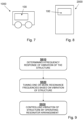
- Plot A shows velocity of vibration of the structure 500 without vibration control.
- Plot B shows velocity of vibration of the structure 500 using a fixed tuning approach to control vibrations.
- Plot C shows velocity of vibration of the structure 500 using the vibration control system 100 and adaptive tuning approach described herein.
- Plot D shows velocity of vibration of the structure 500 using a high resolution swept approach to control vibrations.
- Plot E shows velocity of vibration of the structure 500 using a low resolution swept approach to control vibrations. Peak velocity is indicated in dashed line. RMS velocity is indicated in dotted line.
- the vibration control system 100 provides good performance in control (e.g., attenuation) of vibration of the structure.
- the vehicle comprises a vibration control system 100.
- the vibration control system 100 is in accordance with that described herein, and may comprise any or all features of vibration control system 100 described above.
- the structure 2000 comprises a vibration control system 100.
- the vibration control system 100 is in accordance with that described herein, and may comprise any or all features of vibration control system 100 described above.
- a method of controlling vibration of a structure uses a resonator arrangement for controlling vibration of the structure by absorbing energy therefrom.
- the resonator arrangement is tunable to tune one or more resonance frequencies of the resonator arrangement.
- Step S910 comprises determining a frequency response of vibration of the structure.
- Step S920 comprises tuning one or more resonance frequencies of the resonator arrangement based on the determined frequency response of vibration of the structure.
- Step 830 comprises controlling the vibration of the structure by operating the tuned resonator arrangement.
Landscapes
- Engineering & Computer Science (AREA)
- Physics & Mathematics (AREA)
- General Engineering & Computer Science (AREA)
- General Physics & Mathematics (AREA)
- Automation & Control Theory (AREA)
- Acoustics & Sound (AREA)
- Aviation & Aerospace Engineering (AREA)
- Mechanical Engineering (AREA)
- Vibration Prevention Devices (AREA)
Abstract
According to the present disclosure there is provided a vibration control system for controlling vibration of a structure, the vibration control system comprising: a resonator arrangement for controlling vibration of the structure by absorbing energy therefrom, the resonator arrangement being tunable to tune one or more resonance frequencies of the resonator arrangement; and a controller configured to: determine a frequency response of vibration of the structure; tune the one or more resonance frequencies of the resonator arrangement based on the determined frequency response of vibration of the structure; and control vibration of the structure by operating the tuned resonator arrangement.
Description
- The present invention relates to a vibration control system. The present invention further relates to a vehicle or structure comprising a vibration control system. The present invention further relates to a method of controlling vibration.
- The vibrations of heavy machinery, for example engines, during their operation can have an adverse effect on the bodies or structures on which said machinery is mounted. For example, the vibration of an engine mounted in vehicles including aircraft, watercraft and land-going vehicles, can impact vehicle efficiency, accuracy of instrumentation, vehicle noise, and stability.
- Vibration control systems are desirable in many settings in order to mitigate the impact of the vibration. Known vibration control systems employ resonator arrangements to control vibration of a structure by absorbing energy therefrom. The tuning of the resonator arrangement may be swept across a frequency band to control frequency responses of vibrations of a structure within said band. However, actual frequency response of vibrations of the structure are not considered during the sweeping of the tuning of the resonator arrangement.
- According to a first aspect of the present invention, there is provided a vibration control system for controlling vibration of a structure, the vibration control system comprising: a resonator arrangement for controlling vibration of the structure by absorbing energy therefrom, the resonator arrangement being tunable to tune one or more resonance frequencies of the resonator arrangement; and a controller configured to: determine a frequency response of vibration of the structure; tune the one or more resonance frequencies of the resonator arrangement based on the determined frequency response of vibration of the structure; and control vibration of the structure by operating the tuned resonator arrangement.
- In one example, the resonator arrangement comprises one or more shunted electromechanical transducers.
- In one example, shunt impedances are analogue.
- In one example, the controller is configured to: determine the frequency response of vibration of the structure; tune the one or more resonance frequencies of the resonator arrangement to a tuning corresponding to specific frequencies of vibration of the structure; and repeat the preceding steps.
- In one example, the controller is configured to: periodically update the tuning of the resonator arrangement.
- In one example, the specific frequencies of vibration of the structure frequency of vibration of the structure are frequencies of highest magnitude of vibration of the structure.
- In one example, the controller is configured to distribute the resonance frequencies of the resonator arrangement around one or more frequencies of highest magnitude of vibration of the structure.
- In one example, the resonator arrangement comprises one or more single degree of freedom actuators.
- In one example, the resonator arrangement comprises one or more multiple degree of freedom actuators.
- In one example, the resonator arrangement comprises one or more electromechanical actuators.
- According to a second aspect of the present invention, there is provided a vehicle or structure comprising the vibration control system according to the first aspect of the present invention.
- The second aspect of the present invention may incorporate any or all of the features of the first aspect of the present invention, as desired or as appropriate.
- According to a third aspect of the present invention, there is provided a method of controlling vibration of a structure using a resonator arrangement for controlling vibration of the structure by absorbing energy therefrom, the resonator arrangement being tunable to tune one or more resonance frequencies of the resonator arrangement, the method comprising: determining a frequency response of vibration of the structure; tuning one or more resonance frequencies of the resonator arrangement based on the determined frequency response of vibration of the structure; and controlling vibration of the structure by operating the tuned resonator arrangement.
- Embodiments of the invention will now be described by way of example only with reference to the figures, in which:
-
Figure 1 shows a vibration control system; -
Figure 2 shows a first example of a vibration control system; -
Figure 3 shows a second example of a vibration control system; -
Figure 4 shows a third example of a vibration control system; -
Figure 5 shows a fourth example of a vibration control system; -
Figure 6 shows plots of attenuation in kinetic energy using different vibration control approaches; -
Figure 7 shows a vehicle comprising a vibration control system; -
Figure 8 shows a structure comprising a vibration control system; and -
Figure 9 shows general methodology principles. - A vibration control system is described herein. An important feature of the present invention is that a resonator arrangement is tuned based on a determined frequency response of vibration of a structure. This may be known as an "adaptive tuning" approach, where the tuning is adapted based on the determined frequency response of vibration of the structure. A key benefit of the present approach is the ability to adapt to the modal frequencies of the structure. Vibration of the structure may result in a frequency response, or profile, having one or more peak frequencies which it is desired to control. Prior art approaches seek to sweep tuning of a resonator arrangement without considering the frequency response of vibration of the structure to be controlled. That is, prior art approaches do not incorporate adaptive tuning. Further detail will be provided herein.
- For avoidance of doubt, the frequency response of vibration of the structure is an investigation of the vibration of the structure in the frequency domain. This enables the determination of frequency components which are prominent, or dominant, in the vibration of the structure. These frequency components may be related to fundamental movements of the structure, which may relate to the nature of the structure (e.g., its constituent parts or arrangement of parts). In the present invention, the tuning is based on the determined frequency response of vibration of the structure. Furthermore, tuning may be switched (e.g., abruptly, or discontinuously, changed) to control different frequencies of vibration, rather than swept (e.g., continuously changed) as in prior art approaches.
- Referring to
Figure 1 , avibration control system 100 is shown. Thevibration control system 100 is for controlling vibration of astructure 500. - The
vibration control system 100 comprises aresonator arrangement 110. Theresonator arrangement 110 is for controlling vibration of thestructure 500 by absorbing energy therefrom. Theresonator arrangement 110 is tunable to tune one or more resonance frequencies of theresonator arrangement 110. - The
vibration control system 100 comprises acontroller 120. Thecontroller 120 is configured to determine a frequency response of vibration of thestructure 500. Thecontroller 120 is configured to tune the one or more resonance frequencies of theresonator arrangement 110 based on the determined frequency response of vibration of thestructure 500. That is, tuning of theresonator arrangement 110 is based on the determined frequency response of vibration of thestructure 500. - The
controller 120 is configured to control the vibration of thestructure 500 by operating the tunedresonator arrangement 110. - Advantageously, in this way, specific frequencies of vibration of the structure can be targeted and controlled, without sweeping across a band of frequencies to provide control of structural vibrations. Furthermore, the present
vibration control system 100 is easier and cheaper to implement using analogue circuitry when compared with a sweep approach. Despite the difference in approach, comparable performance (i.e., level of control of vibration of the structure) is achieved. - Further detail on the
vibration control system 100 will be provided below. - In broad terms, the resonance frequency of the
resonator arrangement 110 can be tuned using shunt impedance. By tuning theresonator arrangement 110 using shunt impedance in consideration of, or based on, the frequency response of vibration of thestructure 500, targeted vibration control of vibrations of thestructure 500 can be provided. In the present context, use of shunt circuits causes electrical current to be distributed between the shunt circuit and theresonator arrangement 110. In this way, the current provided to resonators of theresonator arrangement 110 can be altered, thereby to change (or "tune") the resonance frequency of theresonator arrangement 110. It will be well understood that the amount of electrical current distributed between the shunt circuit and theresonator arrangement 110 depends on the value of the shunt impedance of the shunt circuit. The value of the shunt impedance of the shunt circuit is a function of resistance, inductance, and capacitance of the shunt circuit (e.g., of components of the shunt circuit). It will be appreciated from the description herein that the resonance frequency of the resonator arrangement may correspond with a resonance frequency of one or more resonators of theresonator arrangement 110, or of theresonator arrangement 110 as a whole. - The
vibration control system 100 may be provided in a metamaterial. The metamaterial maybe connectable or attachable to thestructure 500, or otherwise cooperate with thestructure 500 to control vibrations thereof. - The
resonator arrangement 110 comprises one ormore resonators 112. Theresonators 112 may be of any suitable form, as will be understood by those skilled in the art. Exemplary and highlyadvantageous resonators 112 include electromechanical transducers. An example of an electromechanical transducer may be an electromechanical actuator. Electromechanical transducers or actuators may be operable to provide high levels of absorption of vibrational energy of thestructure 500. - The
vibration control system 100 further comprises a tuning arrangement in the form of ashunt circuit arrangement 114. Theshunt circuit arrangement 114 comprises one ormore shunt circuits 116. Theshunt circuits 116 may be, or considered to be, part of theresonator arrangement 110. Alternatively, theshunt circuits 116 may be, or be considered to be, separate to theresonator arrangement 110. That is, theresonator arrangement 110 andshunt circuit arrangement 114 may be separate, or distinct, arrangements. - The
shunt circuits 116 may be realised in analogue (i.e., an analogue shunt circuit) or in digital (i.e., a digital shunt circuit). Theshunt circuit arrangement 114 may comprise one or more analogue shunt circuits and one or more digital shunt circuits - that is, a combination of one or more analogue shunt circuits and one or more digital shunt circuits. - The
shunt circuit arrangement 114 may be provided in parallel to theresonator arrangement 110. In an example, eachresonator 112 of theresonator arrangement 110 may be provided with one or moreparallel shunt circuits 116. - In an analogue implementation of a
shunt circuit 116, theshunt circuit 116 may be switchable between components thereby to vary the shunt impedance of theshunt circuit 116. In this way, aswitchable shunt circuit 116 is realised. The adaptive tuning approach of the present invention facilitates the use of analogue shunt impedances, or analogue shunt circuits. Alternatively, adigital shunt circuit 116 may be implemented. In the context of the present invention,shunt circuits 116 enable control of multiple modes of vibration of the structure by tuning the resonance frequency of theresonator arrangement 110 to correspond with said modes of vibration. - As above, the
controller 120 is configured to determine a frequency response of vibration of thestructure 500. Thecontroller 120 may predetermine the frequency response of vibration of the structure 500 (i.e., prior to operation of the vibration control system 100), or may be provided with the frequency response of the vibration of thestructure 500 prior to operation of thevibration control system 100. Additionally, or alternatively, thecontroller 120 may receive input from a sensor 118 for providing information representative of vibration of thestructure 500. The sensor 118 may be a vibration sensor. The sensor 118 may be in the form of an accelerometer or laser vibrometer. Thecontroller 120 may determine the frequency response of vibration of thestructure 500 using the input provided by the sensor 118. - The
controller 120 tunes the one or more resonance frequencies of theresonator arrangement 110 based on the determined frequency response of vibration of thestructure 500. This may involve determining specific frequencies of vibration of thestructure 500, which may be a plurality of frequencies of maximum amplitude of vibration of thestructure 500. This may be known as a "greatest magnitude" frequency selection approach. This involves a plurality of highest magnitude frequency bins, based on which theresonator arrangement 110 is tuned. Such an approach is highly advantageous, as the frequencies of greatest magnitude, and thus contributing considerably to the vibration of thestructure 500, can be controlled. An exemplary algorithmic approach is as follows: - Input: rate of change of frequency of the structure; structural velocity measured at a single position
- Output: shunt circuit component values (e.g., resistance (R), inductance (L), capacitance (C))
- 1. Calculate frequency domain response using a logarithmically distributed fast Fourier transform of length non-uniform fast Fourier transform (samples).
- 2. Sort frequency vector in descending order of frequency response magnitude.
- 3. Truncate frequency vector to first N (corresponding to the N highest magnitudes).
- 4. Calculate required R, L and C values to achieve selected tuning frequencies and damping ratio.
- 5. Implement new component values.
- 6. Hold for an update period of length n (samples).
- 7. Repeat.
- Examples of
vibration control systems 100 within the scope of the present invention are illustrated inFigures 2 to 5 . - Referring to
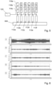
Figure 2 , a first example of thevibration control system 100 is shown. In this example, theresonator arrangement 110 comprises asingle resonator 112, and theshunt circuit arrangement 114 comprises a plurality ofshunt circuits 116. Each shunt circuit has a fixed shunt impedance. Thecontroller 120 is configured to tune the one or more resonance frequencies of theresonator arrangement 110 by switching to, or between, theshunt circuits 116. Thecontroller 120 is configured to control the frequency of vibration of thestructure 500 by operating the tunedresonator arrangement 110. - Referring to
Figure 3 , a second example of thevibration control system 100 is shown. In this example, theresonator arrangement 110 comprises asingle resonator 112, and theshunt circuit arrangement 114 comprises asingle shunt circuit 116. Theshunt circuit 116 is a variable impedance shunt circuit. Thecontroller 120 is configured to tune the one or more resonance frequencies of theresonator arrangement 110 by switching the shunt impedance of theshunt circuit 116. Thecontroller 120 is configured to control the frequency of vibration of thestructure 500 by operating the tunedresonator arrangement 110. - Referring to
Figure 4 , a third example of thevibration control system 100 is shown. In this example, theresonator arrangement 110 comprises a plurality ofresonators 112a - 112f, and theshunt circuit arrangement 114 comprises a plurality ofshunt circuits 116a - 116f. Eachresonator 112 is connected in parallel with acorresponding shunt circuit 116. Each of the plurality ofshunt circuits 116a - 116f is a variable impedance shunt circuit. Thecontroller 120 is configured to tune the one or more resonance frequencies of theresonator arrangement 110 by switching the shunt impedance of each shunt circuit. Eachresonator 112 of theresonator arrangement 110 may be operable, or operated, simultaneously, in turn and/or at different times based on the frequency it is desired to control. For example, a first resonator may be operated with an associated shunt circuit of a particular shunt impedance thereby to control a particular frequency response of vibration of thestructure 500, and simultaneously, or subsequently, another resonator may be operated with an associated shunt circuit of a particular shunt impedance thereby to control (another) particular frequency response of vibration of thestructure 500. - Referring to
Figure 5 , a fourth example of thevibration control system 100 is shown. In this example, theresonator arrangement 110 comprises a plurality ofresonators 112a - 112f, and theshunt circuit arrangement 114 comprises a plurality ofshunt circuits 116a - 116r. In this example, eachresonator 112 is connected in parallel with a plurality ofcorresponding shunt circuits 116. In this example, theshunt circuits 116a - 116r are fixed impedance shunt circuits. Thecontroller 120 is configured to tune the one or more resonance frequencies of theresonator arrangement 110 by switching to, or between, theshunt circuits 116. That is, thecontroller 120 may switch between the fixedshunt circuits 116 corresponding with aparticular resonator 112. An example includes switching betweenshunt circuits resonator 112a, and so on for theother resonators 112b - 112f of theresonator arrangement 110. Thecontroller 120 is configured to control the frequency of vibration of thestructure 500 by operating the tunedresonator arrangement 110. Whilst in this example a plurality of fixed shunt circuits are illustrated, the person skilled in the art will appreciate that each resonator may be provided with a single switchable shunt circuit (as inFigure 4 ), where each shunt circuit is switchable between components thereby to vary the shunt impedance of the respective shunt circuit. - Further features of the present invention, relevant to all examples of the
vibration control system 100, are described below. - In an example, the
controller 120 is configured to determine the frequency response of vibration of thestructure 500; tune the one or more resonance frequencies of theresonator arrangement 110 to a tuning corresponding to specific frequencies of vibration of thestructure 500. Thecontroller 120 may be configured to repeat the determination of the frequency response of vibration of the structure and tune (e.g., retune) the one or more resonance frequencies. In this way, the tuning may be updated. - In an example, the
controller 120 may be configured to periodically update the tuning of theresonator arrangement 110. That is, after a suitable, or predetermined, time period, thecontroller 120 may update the tuning of theresonator arrangement 110. In this way, the tuning may be updated, which enables multiple peak modes of vibration to be controlled and considered. Moreover, in this way, the activevibration control system 100 is adaptive, as it can be retuned to control particular frequencies at a given point in time. - Velocity feedback may be used to adaptively weight the switching rate. That is, the
resonator arrangement 110 may be tuned to control a specific frequency of vibration of thestructure 500 based on the velocity of vibration of thestructure 500. In this way, theresonator arrangement 110 may be tuned to a specific frequency based on the velocity of vibration of thestructure 500 at that frequency. This enables an approach wherein theresonator arrangement 110 is tuned to large peaks in the velocity for a greater amount of time (thus providing improved control of large velocity peaks) and wherein theresonator arrangement 110 is tuned to frequencies with little to no velocity for a lesser amount of time (as these do not contribute substantially to the overall vibration response of the structure 500). - The specific frequencies of vibration of the structure (which may be those to which the resonator arrangement is tuned) may be frequencies of highest magnitude of vibration of the structure. Such frequencies may be known as "peak frequencies of vibration of the structure", or "peak modes of vibration of the structure".
- In an example, the
controller 120 is configured to distribute the resonance frequencies of theresonator arrangement 110 around one or more frequencies of highest magnitude of vibration of thestructure 500. In other words, thecontroller 120 may be configured to distribute the resonance frequencies of theresonator arrangement 110 in a band around the peak frequencies of vibration of thestructure 500. In this way, a specific frequency of vibration of the structure can be targeted, so as to absorb the energy thereof. - The
resonator arrangement 110 may comprise one or more single degree of freedom electromechanical transducers, or actuators. Advantageously, a single degree of freedom actuator may absorb a single mode of vibration, which may improve robustness and/or simplify tuning of theresonator arrangement 110. - The
resonator arrangement 110 may comprise one or more multiple degree of freedom electromechanical transducers, or actuators. Advantageously, a multiple degree of freedom actuator may absorb multiple modes of vibration, which may improve vibration control and/or provide a more flexiblevibration control system 100. - Referring to
Figure 6 , attenuation in the kinetic energy achieved by the present adaptive tuning approach, compared with other approaches, are compared. Plot A shows velocity of vibration of thestructure 500 without vibration control. Plot B shows velocity of vibration of thestructure 500 using a fixed tuning approach to control vibrations. Plot C shows velocity of vibration of thestructure 500 using thevibration control system 100 and adaptive tuning approach described herein. Plot D shows velocity of vibration of thestructure 500 using a high resolution swept approach to control vibrations. Plot E shows velocity of vibration of thestructure 500 using a low resolution swept approach to control vibrations. Peak velocity is indicated in dashed line. RMS velocity is indicated in dotted line. As will be appreciated fromFigure 6 , thevibration control system 100 provides good performance in control (e.g., attenuation) of vibration of the structure. - Referring to
Figure 7 , avehicle 1000 is shown. The vehicle comprises avibration control system 100. Thevibration control system 100 is in accordance with that described herein, and may comprise any or all features ofvibration control system 100 described above. - Referring to
Figure 8 , astructure 2000 is shown. Thestructure 2000 comprises avibration control system 100. Thevibration control system 100 is in accordance with that described herein, and may comprise any or all features ofvibration control system 100 described above. - Referring to
Figure 9 , a method of controlling vibration of a structure is shown. The method uses a resonator arrangement for controlling vibration of the structure by absorbing energy therefrom. The resonator arrangement is tunable to tune one or more resonance frequencies of the resonator arrangement. Step S910 comprises determining a frequency response of vibration of the structure. Step S920 comprises tuning one or more resonance frequencies of the resonator arrangement based on the determined frequency response of vibration of the structure. Step 830 comprises controlling the vibration of the structure by operating the tuned resonator arrangement.
Claims (12)
- A vibration control system for controlling vibration of a structure, the vibration control system comprising:a resonator arrangement for controlling vibration of the structure by absorbing energy therefrom, the resonator arrangement being tunable to tune one or more resonance frequencies of the resonator arrangement; anda controller configured to:determine a frequency response of vibration of the structure;tune the one or more resonance frequencies of the resonator arrangement based on the determined frequency response of vibration of the structure; andcontrol the vibration of the structure by operating the tuned resonator arrangement.
- The vibration control system according to claim 1, wherein the resonator arrangement comprises one or more shunted electromechanical transducers.
- The vibration control system according to claim 2, wherein shunt impedances are analogue.
- The vibration control system according to any one of the preceding claims, wherein the controller is configured to:determine the frequency response of vibration of the structure;tune the one or more resonance frequencies of the resonator arrangement to a tuning corresponding to specific frequencies of vibration of the structure; andrepeat the preceding steps.
- The vibration control system according to claim 4, wherein the controller is configured to:periodically update the tuning of the resonator arrangement.
- The vibration control system according to claim 4 or 5, wherein the specific frequencies of vibration of the structure are frequencies of highest magnitude of vibration of the structure.
- The vibration control system according to claim 6, wherein the controller is configured to distribute the resonance frequencies of the resonator arrangement around one or more frequencies of highest magnitude of vibration of the structure.
- The vibration control system according to any one of the preceding claims, wherein the resonator arrangement comprises one or more single degree of freedom actuators.
- The vibration control system according to any one of the preceding claims, wherein the resonator arrangement comprises one or more multiple degree of freedom actuators.
- The vibration control system according to any one of the preceding claims, wherein the resonator arrangement comprises one or more electromechanical actuators.
- A vehicle or structure comprising the vibration control system according to any one of the preceding claims.
- A method of controlling vibration of a structure using a resonator arrangement for controlling vibration of the structure by absorbing energy therefrom, the resonator arrangement being tunable to tune one or more resonance frequencies of the resonator arrangement, the method comprising:determining a frequency response of vibration of the structure;tuning one or more resonance frequencies of the resonator arrangement based on the determined frequency response of vibration of the structure; andcontrolling the vibration of the structure by operating the tuned resonator arrangement.
Priority Applications (4)
| Application Number | Priority Date | Filing Date | Title |
|---|---|---|---|
| EP23275066.1A EP4450847A1 (en) | 2023-04-21 | 2023-04-21 | Vibration control system, vehicle, structure, and method |
| AU2024258608A AU2024258608A1 (en) | 2023-04-21 | 2024-04-15 | Vibration control system, vehicle, structure, and method |
| PCT/GB2024/050979 WO2024218475A1 (en) | 2023-04-21 | 2024-04-15 | Vibration control system, vehicle, structure, and method |
| EP24719882.3A EP4698798A1 (en) | 2023-04-21 | 2024-04-15 | Vibration control system, vehicle, structure, and method |
Applications Claiming Priority (1)
| Application Number | Priority Date | Filing Date | Title |
|---|---|---|---|
| EP23275066.1A EP4450847A1 (en) | 2023-04-21 | 2023-04-21 | Vibration control system, vehicle, structure, and method |
Publications (1)
| Publication Number | Publication Date |
|---|---|
| EP4450847A1 true EP4450847A1 (en) | 2024-10-23 |
Family
ID=86184956
Family Applications (1)
| Application Number | Title | Priority Date | Filing Date |
|---|---|---|---|
| EP23275066.1A Ceased EP4450847A1 (en) | 2023-04-21 | 2023-04-21 | Vibration control system, vehicle, structure, and method |
Country Status (1)
| Country | Link |
|---|---|
| EP (1) | EP4450847A1 (en) |
Citations (7)
| Publication number | Priority date | Publication date | Assignee | Title |
|---|---|---|---|---|
| US4940914A (en) * | 1986-05-26 | 1990-07-10 | Bridgestone Corporation | Vibration absorbing apparatus |
| US5783898A (en) * | 1996-02-26 | 1998-07-21 | Mcdonnell Douglas Corporation | Piezoelectric shunts for simultaneous vibration reduction and damping of multiple vibration modes |
| US6193032B1 (en) * | 1998-03-02 | 2001-02-27 | The Penn State Research Foundation | Piezoceramic vibration control device and tuning control thereof |
| JP2002070933A (en) * | 2000-08-31 | 2002-03-08 | Nkk Corp | Structure damping device |
| US20020139603A1 (en) * | 2001-03-27 | 2002-10-03 | Albert Aiken | Vehicle center bearing assembly including piezo-based device for vibration damping |
| JP2007040382A (en) * | 2005-08-02 | 2007-02-15 | Tokai Rubber Ind Ltd | Vibration suppression device |
| US20220285604A1 (en) * | 2021-03-05 | 2022-09-08 | Toyota Motor Engineering & Manufacturing North America, Inc. | Systems and methods for adaptive flexural wave absorber |
-
2023
- 2023-04-21 EP EP23275066.1A patent/EP4450847A1/en not_active Ceased
Patent Citations (7)
| Publication number | Priority date | Publication date | Assignee | Title |
|---|---|---|---|---|
| US4940914A (en) * | 1986-05-26 | 1990-07-10 | Bridgestone Corporation | Vibration absorbing apparatus |
| US5783898A (en) * | 1996-02-26 | 1998-07-21 | Mcdonnell Douglas Corporation | Piezoelectric shunts for simultaneous vibration reduction and damping of multiple vibration modes |
| US6193032B1 (en) * | 1998-03-02 | 2001-02-27 | The Penn State Research Foundation | Piezoceramic vibration control device and tuning control thereof |
| JP2002070933A (en) * | 2000-08-31 | 2002-03-08 | Nkk Corp | Structure damping device |
| US20020139603A1 (en) * | 2001-03-27 | 2002-10-03 | Albert Aiken | Vehicle center bearing assembly including piezo-based device for vibration damping |
| JP2007040382A (en) * | 2005-08-02 | 2007-02-15 | Tokai Rubber Ind Ltd | Vibration suppression device |
| US20220285604A1 (en) * | 2021-03-05 | 2022-09-08 | Toyota Motor Engineering & Manufacturing North America, Inc. | Systems and methods for adaptive flexural wave absorber |
Similar Documents
| Publication | Publication Date | Title |
|---|---|---|
| Davis et al. | An actively tuned solid-state vibration absorber using capacitive shunting of piezoelectric stiffness | |
| US6193032B1 (en) | Piezoceramic vibration control device and tuning control thereof | |
| US4940914A (en) | Vibration absorbing apparatus | |
| Fleming et al. | Adaptive piezoelectric shunt damping | |
| Kim et al. | Broadband transmission noise reduction of smart panels featuring piezoelectric shunt circuits and sound-absorbing material | |
| Davis et al. | Tunable electrically shunted piezoceramic vibration absorber | |
| WO2003055063A1 (en) | Tunable piezoelectric micro-mechanical resonator | |
| JPWO2015045794A1 (en) | Resonator and high frequency filter | |
| JP2015502085A (en) | Multi-frequency reconfigurable voltage controlled oscillator (VCO) and method for providing same | |
| US20240372530A1 (en) | Systems and methods for absorption tuning for total wave absorption and reflection | |
| US5608360A (en) | Oscillator formed of high frequency resonators and method of generating high frequency oscillator signal having reduced vibration sensitivity and phase noise and improved loop group delay | |
| Høgsberg et al. | Tuning of vibration absorbers by an effective modal coupling factor | |
| JP4680727B2 (en) | Resonator type filter | |
| WO2024218475A1 (en) | Vibration control system, vehicle, structure, and method | |
| GB2629200A (en) | Vibration control system, vehicle, structure, and method | |
| JPH03219139A (en) | Vibration control device | |
| Jung et al. | Electromagnetic synchronized switch damping for vibration control of flexible beams | |
| US5867450A (en) | State switched acoustic transducer | |
| Chong et al. | A self-tuning piezoelectric vibration absorber with voltage-controlled synthetic inductors and a hill-climbing algorithm | |
| Rzepecki et al. | Semi-active reduction of device casing vibration using a set of piezoelectric elements | |
| Fleming et al. | Adaptive piezoelectric shunt damping | |
| KR101431371B1 (en) | Method and Apparatus for realizing a Generalized Electrical Dynamic Absorber | |
| Kim et al. | Performance test for transmitted noise reduction of smart panels using piezoelectric shunt damping | |
| Lim et al. | Vibration control of an HDD disk-spindle system using piezoelectric bimorph shunt damping: II. Optimal design and shunt damping implementation | |
| Matsuda et al. | Parameter estimation of the system composed of a piezoelectric element and multiple vibration modes |
Legal Events
| Date | Code | Title | Description |
|---|---|---|---|
| PUAI | Public reference made under article 153(3) epc to a published international application that has entered the european phase |
Free format text: ORIGINAL CODE: 0009012 |
|
| STAA | Information on the status of an ep patent application or granted ep patent |
Free format text: STATUS: THE APPLICATION HAS BEEN PUBLISHED |
|
| AK | Designated contracting states |
Kind code of ref document: A1 Designated state(s): AL AT BE BG CH CY CZ DE DK EE ES FI FR GB GR HR HU IE IS IT LI LT LU LV MC ME MK MT NL NO PL PT RO RS SE SI SK SM TR |
|
| STAA | Information on the status of an ep patent application or granted ep patent |
Free format text: STATUS: THE APPLICATION HAS BEEN REFUSED |
|
| 18R | Application refused |
Effective date: 20241031 |