EP4450830A1 - Holding member with actuator cover, and actuator cover - Google Patents
Holding member with actuator cover, and actuator cover Download PDFInfo
- Publication number
- EP4450830A1 EP4450830A1 EP22906983.6A EP22906983A EP4450830A1 EP 4450830 A1 EP4450830 A1 EP 4450830A1 EP 22906983 A EP22906983 A EP 22906983A EP 4450830 A1 EP4450830 A1 EP 4450830A1
- Authority
- EP
- European Patent Office
- Prior art keywords
- actuator
- fluid pressure
- holding
- cover
- section
- Prior art date
- Legal status (The legal status is an assumption and is not a legal conclusion. Google has not performed a legal analysis and makes no representation as to the accuracy of the status listed.)
- Pending
Links
Images




Classifications
-
- F—MECHANICAL ENGINEERING; LIGHTING; HEATING; WEAPONS; BLASTING
- F15—FLUID-PRESSURE ACTUATORS; HYDRAULICS OR PNEUMATICS IN GENERAL
- F15B—SYSTEMS ACTING BY MEANS OF FLUIDS IN GENERAL; FLUID-PRESSURE ACTUATORS, e.g. SERVOMOTORS; DETAILS OF FLUID-PRESSURE SYSTEMS, NOT OTHERWISE PROVIDED FOR
- F15B15/00—Fluid-actuated devices for displacing a member from one position to another; Gearing associated therewith
- F15B15/08—Characterised by the construction of the motor unit
- F15B15/10—Characterised by the construction of the motor unit the motor being of diaphragm type
- F15B15/103—Characterised by the construction of the motor unit the motor being of diaphragm type using inflatable bodies that contract when fluid pressure is applied, e.g. pneumatic artificial muscles or McKibben-type actuators
-
- B—PERFORMING OPERATIONS; TRANSPORTING
- B25—HAND TOOLS; PORTABLE POWER-DRIVEN TOOLS; MANIPULATORS
- B25J—MANIPULATORS; CHAMBERS PROVIDED WITH MANIPULATION DEVICES
- B25J15/00—Gripping heads and other end effectors
- B25J15/0023—Gripper surfaces directly activated by a fluid
-
- B—PERFORMING OPERATIONS; TRANSPORTING
- B25—HAND TOOLS; PORTABLE POWER-DRIVEN TOOLS; MANIPULATORS
- B25J—MANIPULATORS; CHAMBERS PROVIDED WITH MANIPULATION DEVICES
- B25J15/00—Gripping heads and other end effectors
- B25J15/08—Gripping heads and other end effectors having finger members
-
- B—PERFORMING OPERATIONS; TRANSPORTING
- B25—HAND TOOLS; PORTABLE POWER-DRIVEN TOOLS; MANIPULATORS
- B25J—MANIPULATORS; CHAMBERS PROVIDED WITH MANIPULATION DEVICES
- B25J9/00—Program-controlled manipulators
- B25J9/10—Program-controlled manipulators characterised by positioning means for manipulator elements
- B25J9/14—Program-controlled manipulators characterised by positioning means for manipulator elements fluid
- B25J9/142—Program-controlled manipulators characterised by positioning means for manipulator elements fluid comprising inflatable bodies
-
- F—MECHANICAL ENGINEERING; LIGHTING; HEATING; WEAPONS; BLASTING
- F15—FLUID-PRESSURE ACTUATORS; HYDRAULICS OR PNEUMATICS IN GENERAL
- F15B—SYSTEMS ACTING BY MEANS OF FLUIDS IN GENERAL; FLUID-PRESSURE ACTUATORS, e.g. SERVOMOTORS; DETAILS OF FLUID-PRESSURE SYSTEMS, NOT OTHERWISE PROVIDED FOR
- F15B15/00—Fluid-actuated devices for displacing a member from one position to another; Gearing associated therewith
- F15B15/20—Other details, e.g. assembly with regulating devices
Definitions
- the present disclosure relates to a holding member with actuator cover and an actuator cover that protects a fluid pressure actuator.
- PTL 1 discloses a fluid pressure actuator (so-called McKibben-type fluid pressure actuator) having a rubber tube that expands and contracts by air pressure and a sleeve that covers the outer circumferential surface of the tube.
- the sleeve and other parts may rub against the object or dirt and moisture from the object to be held may adhere to the sleeve and other parts, adversely affecting the durability of the fluid pressure actuator, and there was room for improvement in this respect.
- the purpose of the present disclosure is to improve the durability of fluid pressure actuators.
- a holding member with actuator cover comprises: a holding section to be attached to a fluid pressure actuator driven by fluid pressure to hold an object; and an actuator cover that covers the fluid pressure actuator while the holding section is attached to the fluid pressure actuator.
- the holding member with actuator cover of the present disclosure it is possible to prevent the fluid pressure actuator from being rubbed due to contact with an object and to prevent moisture and dirt from adhering to the fluid pressure actuator, thereby improving the durability of the fluid pressure actuator.
- the holding section can be attached to an axial tip side of a cylindrical tube, that expands and contracts, of the fluid pressure actuator, and the actuator cover covers radially outer side of the tube of the fluid pressure actuator.
- the radially outer side of the fluid pressure actuator is covered with the actuator cover and the holding section is attached to the tip of the actuator, therefore, it is possible to effectively prevent the fluid pressure actuator from being rubbed due to contact with an object and to effectively prevent moisture and dirt from adhering to the fluid pressure actuator, thereby further improving the durability of the fluid pressure actuator.
- the actuator cover is integrally formed with the holding section.
- the holding section has a mounting recess into which a mounting protrusion of the fluid pressure actuator can fit.
- the holding section has a claw for holding the object.
- the claw contacts the object more strongly than other parts, thereby increasing the static frictional force with the object and more securely holding the object.
- the holding section has a holding recess for holding the object.
- the holding recess which is concave in the direction away from the object is provided, and the object O can be held as if it were encased in the palm of the hand.
- an actuator cover of the present disclosure comprises: a cover body that covers a fluid pressure actuator; and a holding cover section that covers a holding section attached to an axial tip side of the fluid pressure actuator to hold an object.
- the fluid pressure actuator and the holding section attached to the axial tip side of the fluid pressure actuator can be covered without gaps. Therefore, it is possible to prevent the fluid pressure actuator 1 from being rubbed due to contact with an object and to prevent moisture, dirt, etc. from entering through the gap between the holding cover section and the cover body and adhering to the sleeve, etc.
- the holding cover section has a thinner wall thickness than the cover body.
- the shape of the holding cover section which has a thinner wall thickness and excellent elasticity, can be easily fitted to the external shape of the holding section, which is wider than the fluid pressure actuator in the front view.
- material composing the holding cover section has a lower modulus of longitudinal elasticity than material composing the cover body.
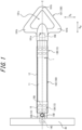
- Figure 1 illustrates a holding member with actuator cover 100 in accordance with one embodiment of the present disclosure attached to a fluid pressure actuator 1.
- the holding member with actuator cover 100 comprises a holding section 101 that is attached to the tip side of the long fluid pressure actuator 1 extending in the right and left directions in Figure 1 to hold an object O, and an actuator cover 102 that covers the fluid pressure actuator 1 from radially outer side while the holding section 101 is attached to the fluid pressure actuator 1.
- the fluid pressure actuator 1 and the holding member with actuator cover 100 have their respective central axes arranged on a common axis C.
- the holding section 101 side along this axis C (right side in Figure 1 ) is the tip side
- the support section 40 side (left side in Figure 1 ) is the base side.
- the direction orthogonal to the axis C is referred to as the radial direction
- the direction away from the axis C along a straight line orthogonal to the axis C is referred to as the radially outer side
- the direction closer to the axis C along a straight line orthogonal to the axis C is referred to as the radially inner side.
- the "axial direction” is indicated as D AX and the "radial direction” is indicated as D R .
- the holding section 101 has an abbreviated triangular shape in the front view illustrated in Figure 1 , and each vertex position of the triangle constitutes a claw 101b that is slightly oriented toward the object O to be held (toward the front side perpendicular to the paper in Figure 1 ).
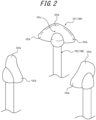
- the area surrounded by the three claws 101b in Figure 1 constitutes a holding recess 101c, which is recessed toward the back perpendicular to the paper in Figure 1 (see Figure 2 for the three-dimensional shape of the holding section 101).
- the claw 101b oriented toward the object O to be held, the claw 101b contacts the object O more strongly than other parts, thereby increasing the static frictional force with the object O and more securely holding the object O.
- the holding recess 101c which is concave in the direction away from the object O, the object O can be held as if it were encased in the palm of the hand.
- the configuration of the claw 101b is not limited to that illustrated in Figures 1 and 2 .
- a sharp claw 101b protruding toward the object O may be employed to bite the claw 101b into the object O to hold the object O more securely. It may also be configured without the claw 101b and/or the holding recess 101c.
- the actuator cover 102 has an abbreviated cylindrical shape and covers the outer circumference surface of the sleeve 12 of the fluid pressure actuator 1 (see Figure 3 , etc.) described below.
- the actuator cover 102 protects the fluid pressure actuator 1.
- the actuator cover 102 protects the fluid pressure actuator 1, especially the sleeve 12, from rubbing by contact with other objects.
- the actuator cover 102 is preferably able to protect the sleeve 12 from getting wet due to moisture or other factors as well as damage to the sleeve 12 caused by such rubbing.
- the actuator cover 102 is preferably waterproof, i.e., a material that does not allow water to pass through.
- the actuator cover 102 can be made hydrophobic or water-repellent to further enhance the waterproofing effect.
- the actuator cover 102 is preferably made of a material that is scratch resistant, waterproof, weather resistant, and heat resistant to protect the sleeve 12.
- the actuator cover 102 preferably has a sufficiently small modulus of elasticity (modulus of longitudinal elasticity) so as not to interfere with the change in shape of the fluid pressure actuator 1.
- the modulus of elasticity of the actuator cover 102 is preferably less than that of the sleeve 12.
- the holding member with actuator cover 100 is formed by elastic materials such as silicone rubber, urethane rubber, chloroprene rubber, acrylonitrile butadiene rubber, ethylene propylene rubber, ethylene propylene diene rubber, fluorine rubber, and natural rubber.
- elastic materials such as silicone rubber, urethane rubber, chloroprene rubber, acrylonitrile butadiene rubber, ethylene propylene rubber, ethylene propylene diene rubber, fluorine rubber, and natural rubber.
- the holding member with actuator cover 100 can be integrally formed, for example, by compression molding, injection molding, or extrusion molding.
- the materials of the holding section 101 and the actuator cover 102 can be optimized to be different while simultaneously integrally forming the holding section 101 and the actuator cover 102.
- Different materials may be used for only a part of the holding section 101.
- the actuator cover 102 may be made of a highly stretchable material compared to the holding section 101 to improve its ability to follow the fluid pressure actuator 1.
- one of the rubber materials mentioned above may be used for the part of the holding section 101 that is in contact with the object O, while plastic or metal or other materials may be used for the other parts to increase rigidity.
- the term "integrally formed" means that a product is formed as a single piece in a mold, and includes the case that a product is formed as a single piece by insert molding, two-color molding, or other means, however, does not include the case to integrate separate parts, which are formed in separate molds, in a subsequent process that does not involve resin molding, such as bonding.
- the holding section 101 and the actuator cover 102 do not necessarily need to be integrally formed at the same time.
- the holding section 101 and the actuator cover 102 which are formed separately, may be glued or welded together to form a single unit.
- the base side of the holding section 101 is preferably coupled to the tip side of the actuator cover 102 without any gap. This configuration prevents moisture, dirt, etc. from entering through the gap between the holding section 101 and the actuator cover 102 and adhering to the sleeve 12, etc.
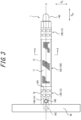
- the fluid pressure actuator 1 comprises a tube 11, a sleeve 12, a first sealing section 13A, a second sealing section 13B, a mounting protrusion 14G, and a restraining member 17.
- Fluid can flow into the tube 11 of the fluid pressure actuator 1 through a connection port 14D provided in the first sealing section 13A.
- the fluid pressure actuator 1 contracts in the axial direction and expands in the radial direction of the fluid pressure actuator 1 due to the inflow of fluid into the tube 11.
- the fluid pressure actuator 1 expands in the axial direction and contracts in the radial direction of the fluid pressure actuator 1 due to the outflow of fluid from the tube 11. In this way, the fluid pressure actuator 1 can function as an actuator by changing its shape.
- Such a fluid pressure actuator 1 is the so-called McKibben type and can be applied as an artificial muscle, as well as a body limb, hand or finger of a robot that requires higher capacity (contractile force).
- the tube 11 is a cylindrical tube that expands and contracts with fluid pressure.
- the tube 11 is made of elastic material, such as butyl rubber, for repeated contraction and expansion due to the fluid.
- the elastic member forming the tube 11 may be NBR (nitrile rubber) with high oil resistance or at least one type selected from the group consisting of hydrogenated NBR, chloroprene rubber and epichlorohydrin rubber.
- the sleeve 12 is cylindrical and covers the outer circumferential surface of the tube 11.
- the sleeve 12 has a stretchable structure made of woven fiber cords oriented in a predetermined direction, and the oriented cords intersect to form a repeated diamond shape. By having this shape, the sleeve 12 pantographically deforms and follows the deformation of the tube 11, regulating axial expansion of the tube 11 and allowing radial expansion of the tube 11.
- Fiber cords such as aromatic polyamide (aramid fiber) or polyethylene terephthalate (PET) are preferred as the fiber cord that makes up the sleeve 12.
- the fiber cords that make up the sleeve 12 are not limited to these types of fiber cords, but may be high-strength fiber cords such as PBO fiber (polyparaphenylene benzobisoxazole), for example.
- the first sealing section 13A and the second sealing section 13B seal the ends (tip side and base side) of the tube 11 in the axial direction, respectively.
- the first sealing section 13A seals the base side of the tube 11 in the axial direction (left side in Figure 3 )
- the second sealing section 13B seals the tip side of the tube 11 in the axial direction (right side in Figure 3 ).
- the first sealing section 13A and the second sealing section 13B are collectively referred to simply as "sealing section 13" when not specifically distinguished.
- the sealing member 14 seals the axial end of the tube 11.
- the sealing member 14 has a head part 14A and a body part 14B extending axially from the head part 14A, as illustrated in Figure 4 .
- the body part 14B is inserted into the tube 11 from the outer side in the axial direction of the tube 11.
- the sealing member 14 may have a coupling part 14C for coupling other members.
- the coupling part 14C protrudes from the head part 14A in the axial direction opposite to the body part 14B.
- the coupling part 14C may have a through hole defined therein, which extends in the radial direction to facilitate coupling other members.
- a support section 40 that supports the fluid pressure actuator 1 is attached to the coupling part 14C of the first sealing section 13A.
- the second sealing section 13B is provided with the mounting protrusion 14G instead of the coupling part 14C, as illustrated in Figure 3 , etc.
- the holding section 101 is attached to the fluid pressure actuator 1 in a removable state by fitting the mounting protrusion 14G into the mounting recess 101a of the holding section 101.
- the sealing member 14 is made of a metal such as stainless steel, but it is not limited to such metals and may be made of hard plastic materials.
- the locking ring 15 is a ring-shaped member that locks the sleeve 12 to the sealing member 14. Specifically, as illustrated in Figure 5 , the sleeve 12 is folded radially outward through the locking ring 15.
- the locking ring 15 has a partially notched notch 15A to allow engagement with the sealing member 14.
- the locking ring 15 may be made of the same metal, hard plastic material, or other material as the sealing member 14, or of natural fibers (natural fiber threads), rubber (e.g., O-rings), or other material.
- the caulking member 16 caulks the tube 11 and the sleeve 12 together with the sealing member 14.
- the caulking member 16 is a cylindrical member that is larger than the outer diameter of the body part 14B of the sealing member 14.
- the caulking member 16 is provided to cover the radially outer side of the portion of the tube 11 and the sleeve 12 into which the sealing member 14 is inserted, and is caulked by the jig to tighten the tube 11 and the sleeve 12 so as to secure them tightly to the sealing member 14.
- the caulking member 16 may be constructed using a metal such as aluminum alloy, brass, or iron. As illustrated in Figure 3 , the outer circumference surface of the caulking member 16 may have an indentation 16A, which is a mark made by the jig.
- the difference between the first sealing section 13A and the second sealing section 13B is whether the sealing member 14 has the connection port 14D and a passage hole 14E.
- the sealing member 14 at the first sealing section 13A has the connection port 14D and the passage hole 14E.
- connection port 14D is where the hose (conduit) connected to the compressor of the drive pressure source of the fluid pressure actuator 1, specifically, gas or liquid, etc., is attached. Fluid that flows in through the connection port 14D passes through the passage hole 14E defined in the interior of the sealing member 14 and flows into the interior of the tube 11.
- the connection port 14D is provided to open toward radially outward of the head part 14A of the sealing member 14.
- the passage hole 14E is formed over the head part 14A and the body part 14B.
- the connection port 14D is connected to the inside of the tube 11 by the passage hole 14E.
- the restraining member 17 is provided on the radially inner side of the sleeve 12.
- the restraining member 17 is provided on the radially inner side of the sleeve 12 from the base side to the tip side in the axial direction.
- the restraining member 17 does not compress in the axial direction, but is deformable only along the radial direction (also referred to as the deflection direction). In other words, the restraining member 17 resists compression along the axial direction at a predetermined position in the circumferential direction of the tube 11 and is bendable and deformable in the orthogonal direction perpendicular to the axial direction (radial direction).
- the restraining member 17 also functions to restrain (regulate) the expansion of the tube 11 (and the sleeve 12) radially outward at a predetermined position in the circumferential direction of the tube 11 where the restraining member 17 is provided.
- the restraining member 17 is formed, for example, using a leaf spring.
- the dimensions of the leaf spring should be selected according to the size of the fluid pressure actuator 1 and the required generating force, and are not limited.
- the material of the leaf spring is also not limited, but typically should be a material that is easy to bend and resistant to compression, such as a metal including stainless steel, etc.
- the restraining member 17 may be made of a thin sheet of carbon fiber reinforced plastic (CFRP). Since CFRP is less susceptible to plastic deformation than metal, the fluid pressure actuator 1 easily returns to its original straight state after bending.
- CFRP carbon fiber reinforced plastic
- the restraining member 17 is provided between the tube 11 and the sleeve 12.
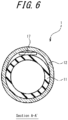
- Figure 6 is a cross-sectional view along the radial direction of the fluid pressure actuator according to the section A-A' in Figure 3 .
- the restraining member 17 may be in close contact with the tube 11 and the sleeve 12, or some gap may be formed between the restraining member 17 and the tube 11 and/or the sleeve 12 and to the sides of the restraining member 17.
- the restraining member 17 may be embedded in the tube 11 or may be provided on the radially inner side of the tube 11.
- the restraining member 17 is provided on a portion of the tube 11 (and the sleeve 12) in the circumferential direction.
- the tube 11 has portions, in the circumferential direction, that are covered by the restraining member 17 and portions that are not covered by the restraining member 17.
- the width of the restraining member 17 is not particularly limited, but based on the outer diameter of the tube 11, it may be approximately half of the outer diameter.
- the restraining member 17 is flat, but it may be curved somewhat along the cross-sectional shape of the tube 11 and the sleeve 12 to the extent that it does not affect the way it flexes.
- the restraining member 17 is provided from the base side to the tip side in the axial direction of the tube 11 and the sleeve 12. Specifically, the restraining member 17 may be provided from the first sealing section 13A to the second sealing section 13B. In this embodiment, the restraining member 17 is approximately equal in length to the tube 11.
- the restraining member 17 need not necessarily be completely provided from the first sealing section 13A to the second sealing section 13B, and the restraining member 17 need not extend to either the first sealing section 13A or the second sealing section 13B (especially on the second sealing section 13B side, which is likely to be the free end when curved).
- the fluid pressure actuator 1 is fixed at the base side by the support section 40, and the tip side is free to move.
- the base side of the fluid pressure actuator 1 is the fixed end and the tip side thereof is the free end.
- the holding section 101 is mounted to the fluid pressure actuator 1 by fitting the mounting protrusion 14G on the tip side (lower side in Fig. 7 ) of the fluid pressure actuator 1 into the mounting recess 101A of the holding section 101.
- the actuator cover 102 extends along the fluid pressure actuator 1 toward the base side and covers a portion of the first sealing section 13A.
- Figure 7 illustrates only one fluid pressure actuator 1 and one holding member with actuator cover 100 that covers it.
- a plurality of fluid pressure actuators 1 and holding member with actuator covers 100 may be arranged so that the holding recesses 101c are oriented inwardly.
- the portion of the tube 11 without the restraining member 17 (the right side of the axis C in Figure 7 ) tries to contract, so the restraining member 17 acts like a backbone, and on the side opposite to the circumferential position of the tube 11 where the restraining member 17 is provided (right side in Figure 7 ), the fluid pressure actuator 1 (specifically, the tube 11 and the sleeve 12) bends in the direction D1.
- This direction D1 is also referred to as the deflection direction.
- the fluid pressure actuator 1 when fluid flows out of the fluid pressure actuator 1, the fluid pressure actuator 1 returns to its original linear posture. This allows the fluid pressure actuator 1 to be used, for example, as a robot arm or fingers of a robot hand.
- the fluid pressure actuator 1 when the fluid pressure actuator 1 is driven to displace the holding section 101 toward direction D1, it can lift an object O placed on the worktable T in cooperation with other fluid pressure actuators 1 not illustrated in Figure 7 .
- the claw 101b provided on the holding section 101 and oriented to protrude slightly in the direction of the object O can contacts the object O more strongly than other parts to hold and lift the object O more securely.
- the holding recess 101c which is concave in the direction away from the object O, the object O can be held as if it were encased in the palm of the hand. This configuration allows, for example, a soft and fragile object O, such as a chicken egg, to be held without damaging it.
- the actuator cover 102 extends along the fluid pressure actuator 1 from the base of the holding section 101 toward the support section 40 (toward the top in Figure 7 ) and covers the fluid pressure actuator 1 from the outside in the radial direction.
- the actuator cover 102 is coupled to the base side of the holding section 101 without any gaps. This configuration prevents, when the object O illustrated in Figure 7 being held, moisture, dirt, etc. from the object O from entering through the gap between the holding section 101 and the actuator cover 102, and adhering to the sleeve 12 and the tube 11.
- the user of the fluid pressure actuator 1 can easily replace the holding member with actuator cover 100 with the most appropriate one according to the size, weight, surface condition, or placement of the object O.
- the holding section 101 can be replaced with the one with a rigid material when the weight of the object O is large, or with the one with a larger holding area when the size of the object O is large.
- both the holding section 101 and the actuator cover 102 are preferably replaced with new ones.
- the holding section 101 and the actuator cover 102 are integrally formed, so the holding section 101 and the actuator cover 102 can be easily replaced at the same time.
- the durability of the fluid pressure actuator 1 can be improved because dirt and moisture can be prevented from entering the gap between the holding section 101 and the actuator cover 102 when the holding member with actuator cover 100 is in use.
- FIG 8 an example of a system using the fluid pressure actuator 1 equipped with the holding member with actuator cover 100 is described.
- the system illustrated in Figure 8 is a gripping system 50 that grips an object O by driving the fluid pressure actuator 1.
- the portion corresponding to the holding member with actuator cover 100 is drawn in bold line.
- the gripping system 50 comprises a pedestal section 51, a strut section 52, a first actuator connector 53, a telescopic actuator 54, a second actuator connector 55, and the fluid pressure actuator 1 equipped with the holding member with actuator cover 100.
- the strut section 52 is standing on the top surface of the pedestal section 51.
- the upper end of the strut section 52 is folded back toward the bottom, and the first actuator connector 53 is coupled to the tip of the strut section 52.
- the telescopic actuator 54 is suspended from the first actuator connector 53.
- the telescopic actuator 54 adjusts the vertical position of the fluid pressure actuator 1.
- the telescopic actuator 54 is not provided with a restraining member 17 like the fluid pressure actuator 1 described above, and can be a general McKibben-type actuator.
- the telescopic actuator 54 contracts and expands along the axial direction (direction of the white arrow in the figure).
- the telescopic actuator 54 simply changes its axial length and cannot be curved like the fluid pressure actuator 1 with the restraining member 17 described above.
- the telescopic actuator 54 may have a restraining member 17 and be able to bend.
- the telescopic actuator 54 is not limited to a McKibben-type actuator, but may be an actuator of another configuration.
- the second actuator connector 55 is coupled to the lower end of the telescopic actuator 54.
- the fluid pressure actuator 1 is suspended from the second actuator connector 55 via the support section 40.
- each of the four fluid pressure actuators 1 there are four fluid pressure actuators 1 and one support section 40 that supports the four fluid pressure actuators 1 at the base side.
- Each of the four fluid pressure actuators 1 is provided with a restraining member 17 spanning the axial direction of the tube 11.
- Each of the four fluid pressure actuators 1 has the holding member with actuator cover 100 attached to the tip side of the tube 11.
- each of the four fluid pressure actuators 1 is provided with the restraining member 17 on the opposite side from the opposing fluid pressure actuator 1. This configuration allows each of the four fluid pressure actuators 1 to bend and deform toward the opposing fluid pressure actuator 1.
- the controller that controls the gripping system 50 can control the pressure in the four fluid pressure actuators 1 to bend and deform each of the fluid pressure actuators 1 in directions that the holding sections 101 attached to the tips of each fluid pressure actuator 1 approach each other to hold the object O.
- the controller may change the number of fluid pressure actuators 1 to be driven or adjust the drive pressure and the height position of the base of the fluid pressure actuators 1 according to the size and weight of the object O to be held. Alternately, the distance between the plurality of fluid pressure actuators 1 may be further adjustable so that the object O can be held in the optimal position according to its size or other factors.
- the holding section 101 is attached to the fluid pressure actuator 1 by fitting the mounting protrusion 14G having approximately hemispherical tip into the cylindrical mounting recess 101a of the holding section 101, but this is not limited to this form.
- a positioning protrusion 101a1 protruding radially inward from a circumferential portion of the mounting recess 101a fits into a positioning recess 14G1 formed in a circumferential portion of the mounting protrusion 14G as illustrated in figure 9B (view of the mounting protrusion 14G from the tip side), so that the rotational position of the holding section 101 with respect to the fluid pressure actuator 1 around the axis C may be determined.
- the holding member in the fluid pressure actuator 1 which is bendable and deformable in the opposite direction from the restraining member 17, the holding member can be mounted in such a way that the surface of the holding section 101 that is to be in contact with the object O (such as the holding recess 101c) can be oriented to the circumferential position opposite to the circumferential position of the restraining member 17. Therefore, the circumferential alignment between the bending direction of the fluid pressure actuator 1 and the surface to be in contact with the object O in the holding section 101 can be facilitated.
- a means may be further provided to align the circumferential position of the restraining member 17 with the rotational position of the mounting protrusion 14G.
- the holding section 101 side may have a positioning recess and the mounting protrusion 14G may have a positioning protrusion, as long as the rotational position of the holding section 101 with respect to the mounting protrusion 14G around the axis C is fixed in a certain direction.
- the holding member with actuator cover 100 is configured to comprise: the holding section 101 to be attached to the fluid pressure actuator 1 driven by fluid pressure to hold the object O; and the actuator cover 102 that covers the fluid pressure actuator 1 while the holding section 101 is attached to the fluid pressure actuator 1.
- the holding section 101 is configured so that it can be attached to the axial tip side of the cylindrical tube 11, that expands and contracts, of the fluid pressure actuator 1, and the actuator cover 102 is configured to cover radially outer side of the tube 11 of the fluid pressure actuator 1.
- the actuator cover 102 is configured to be integrally formed with the holding section 101.
- the gap between the holding section 101 and the actuator cover 102 can be eliminated, therefore it is possible to prevent moisture, dirt, etc. from entering through the gap between the holding section 101 and the actuator cover 102 and adhering to the sleeve 12 and other parts.
- the holding section 101 is configured to have the mounting recess 101a into which the mounting protrusion 14G of the fluid pressure actuator 1 can fit.
- the holding section 101 can be easily attached to and detached from the fluid pressure actuator 1, therefore, maintenance can be easily performed at the timing of a change in the type of object O to be held or at other times.
- the holding section 101 is configured to have the claw 101b for holding the object O.
- the claw 101b contacts the object O more strongly than other parts, thereby increasing the static frictional force with the object O and more securely holding the object O.
- the holding section 101 is configured to have the holding recess 101c for holding the object O.
- the fluid pressure actuator 1 is configured to be bendable and deformable in a predetermined direction
- the holding section 101 is configured to have the positioning part (the positioning protrusion 101a1) for mounting the holding section 101 to the fluid pressure actuator 1 with the surface to hold the object O oriented in the predetermined direction.
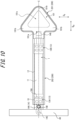
- the actuator cover 200 is a cover member that covers from the outside the long fluid pressure actuator 1 extending in the right and left directions in Figure 10 and the holding section 101 that is attached to the tip side (right side in Figure 10 ) of the fluid pressure actuator 1 to hold an object O.
- the fluid pressure actuator 1 and the actuator cover 200 have their respective central axes arranged on a common axis C.
- the holding section 101 side (right side in Figure 10 ) along this axis C is the tip side
- the support section 40 side (left side in Figure 10 ) is the base side.
- the direction orthogonal to the axis C is referred to as the radial direction
- the direction away from the axis C along a straight line orthogonal to the axis C is referred to as the radially outer side
- the direction closer to the axis C along a straight line orthogonal to the axis C is referred to as the radially inner side.
- the "axial direction” is indicated as D AX and the "radial direction” is indicated as D R .
- the holding section 101 has an abbreviated triangular shape in the front view illustrated in Figure 10 , and each vertex position of the triangle constitutes a claw 101b that is slightly oriented toward the object O to be held (toward the front side perpendicular to the paper in Figure 10 ).
- the area surrounded by the three claws 101b in Figure 10 constitutes a holding recess 101c, which is recessed toward the back perpendicular to the paper in Figure 10 (see Figure 2 for the three-dimensional shape of the holding recess 101c).
- the claw 101b oriented toward the object O to be held, the claw contacts the object O more strongly than other parts, thereby increasing the static frictional force with the object O and more securely holding the object O.
- the holding recess 101c which is concave in the direction away from the object O, the object O can be held as if it were encased in the palm of the hand.
- the holding section 101 is not coupled to the actuator cover 200.
- the actuator cover 200 is configured to cover both the fluid pressure actuator 1 and the holding section 101 from the outside.
- the actuator cover 200 comprises a cover body 202 that covers a fluid pressure actuator 1; and a holding cover section 201 that covers the holding section 101 to hold an object O.
- the cover body 202 has an abbreviated cylindrical shape and covers the outer circumference surface of the sleeve 12 of the fluid pressure actuator 1.
- the cover body 202 protects the fluid pressure actuator 1.
- the cover body 202 protects the fluid pressure actuator 1, especially the sleeve 12, from rubbing by contact with other objects.
- the cover body 202 is preferably made of a material that is scratch resistant, waterproof, weather resistant, and heat resistant to protect the sleeve 12.
- the cover body 202 preferably has a sufficiently small modulus of elasticity (modulus of longitudinal elasticity) so as not to interfere with the change in shape of the fluid pressure actuator 1.
- the modulus of elasticity of the cover body 202 is preferably less than that of the sleeve 12.
- the holding cover section 201 when attached to the holding section 101, has a shape that follows the outline of the holding section 101, and has an abbreviated triangular shape in the front view illustrated in Figure 10 .
- the holding cover section 201 covers the outer circumferential surface of the holding section 101.
- the holding cover section 201 protects the holding section 101.
- the holding cover section 201 not only protects the holding section 101, but also prevents moisture and other substances from entering between the fluid pressure actuator 1 and the cover body 202.
- the holding cover section 201 and the cover body 202, which constitute the actuator cover 200 are coupled without gaps, and the holding cover section 201 completely closes the tip side of the cover body 202.
- This configuration prevents moisture and dirt caused by the object O from entering from the tip side (right side in Figure 10 ) of the fluid pressure actuator 1 when the object O is held.
- the actuator cover 200 can then be replaced to remove moisture, dirt, etc. from the tip side.
- the holding cover section 201 should also be waterproof, i.e., a material that does not allow water to pass through. Furthermore, the holding cover section 201 can be provided with hydrophobic or water-repellent properties to further enhance the waterproofing effect. Note, that there may be a gap between the holding cover section 201 and the cover body 202.
- the wall thickness of the holding cover section 201 is thinner than that of the cover body 202 to provide elasticity. This configuration allows the shape of the holding cover section 201 to easily fit the outline of the holding section 101, which is wider than the fluid pressure actuator 1 in the front view illustrated in Figure 10 .
- the actuator cover 200 can be formed by elastic materials such as silicone rubber, urethane rubber, chloroprene rubber, acrylonitrile butadiene rubber, ethylene propylene rubber, ethylene propylene diene rubber, fluorine rubber, natural rubber, etc.
- elastic materials such as silicone rubber, urethane rubber, chloroprene rubber, acrylonitrile butadiene rubber, ethylene propylene rubber, ethylene propylene diene rubber, fluorine rubber, natural rubber, etc.
- the use of these materials improves the gripping force on the object O by interposing the holding cover section 201, a rubber-based member, between the object O and the holding section 101.
- the cover body 202 is an highly stretchable elastic member, it is less likely to interfere with the deformation of the fluid pressure actuator 1.
- the actuator cover 200 can be integrally formed, for example, by compression molding, injection molding, or extrusion molding.
- the materials of the holding cover section 201 and the cover body 202 can be optimized by using different materials for them while simultaneously integrally molding the holding cover section 201 and the cover body 202.
- the shape of the holding cover section 201 can be easily fitted to the outline of the holding section 101, which is wider than the fluid pressure actuator 1 in the front view illustrated in Figure 10 .
- the shape of the actuator cover 200 when formed may be made to generally match the external shape of the fluid pressure actuator 1 and the holding section 101.
- This configuration allows the shape of the holding cover section 201 to be easily fitted to the outline of the holding section 101 without making the wall thickness of the holding cover section 201 thinner than that of the cover body 202 or the material of the holding cover section 201 more elastic than that of the cover body 202.
- the holding cover section 201 and the cover body 202 do not necessarily need to be integrally formed at the same time.
- the holding cover section 201 and the cover body 202 which are formed separately, can be integrated by bonding or welding.
- the base side of the holding cover section 201 and the tip side of the cover body 202 is preferably coupled without gaps. This configuration prevents moisture, dirt, etc. from entering through the gap between the holding cover section 201 and the cover body 202 and adhering to the sleeve 12 and other parts.
- the holding cover section 201 is configured to have a thinner wall thickness than the cover body 202.
- the shape of the holding cover section 201 which has a thin wall and excellent elasticity, can be easily fitted to the external shape of the holding section 101, which is wider than the fluid pressure actuator 1 in the front view.
- the material composing the holding cover section 201 is configured to have a lower modulus of longitudinal elasticity than the material composing the cover body 202.
- the shape of the holding cover section 201 which has a small modulus of longitudinal elasticity and excellent elasticity, can be easily fitted to the external shape of the holding section 101, which is wider than the fluid pressure actuator 1 in the front view.
- the holding member with actuator cover 100 in this embodiment is configured with a holding section 101 that is triangular in shape in the front view, but is not limited to this configuration.
- the shape of the holding section 101 can adopt various shapes depending on the shape, size, weight, surface condition, etc. of the object O to be held.
- the present disclosure relates to a holding member with actuator cover 100 and an actuator cover 200 to be attached to a fluid pressure actuator 1.
Landscapes
- Engineering & Computer Science (AREA)
- Mechanical Engineering (AREA)
- Physics & Mathematics (AREA)
- Fluid Mechanics (AREA)
- General Engineering & Computer Science (AREA)
- Robotics (AREA)
- Chemical & Material Sciences (AREA)
- Analytical Chemistry (AREA)
- Actuator (AREA)
Abstract
Description
- This application claims priority based on
Japanese Patent Application No. 2021-205598 filed on December 17, 2021 - The present disclosure relates to a holding member with actuator cover and an actuator cover that protects a fluid pressure actuator.
- Fluid pressure actuators that use gas or liquid to expand and contract tubes have been known. For example,
PTL 1 discloses a fluid pressure actuator (so-called McKibben-type fluid pressure actuator) having a rubber tube that expands and contracts by air pressure and a sleeve that covers the outer circumferential surface of the tube. - PTL 1:
JP 2021-088999 A1 - However, in the conventional fluid pressure actuators described above, the sleeve and other parts may rub against the object or dirt and moisture from the object to be held may adhere to the sleeve and other parts, adversely affecting the durability of the fluid pressure actuator, and there was room for improvement in this respect.
- The purpose of the present disclosure, made in view of such circumstances, is to improve the durability of fluid pressure actuators.
- This disclosure was made to solve the above technical problem, and a holding member with actuator cover according to the present disclosure comprises: a holding section to be attached to a fluid pressure actuator driven by fluid pressure to hold an object; and an actuator cover that covers the fluid pressure actuator while the holding section is attached to the fluid pressure actuator.
- According to the holding member with actuator cover of the present disclosure, it is possible to prevent the fluid pressure actuator from being rubbed due to contact with an object and to prevent moisture and dirt from adhering to the fluid pressure actuator, thereby improving the durability of the fluid pressure actuator.
- In the holding member with actuator cover of the present disclosure, it is preferable that the holding section can be attached to an axial tip side of a cylindrical tube, that expands and contracts, of the fluid pressure actuator, and the actuator cover covers radially outer side of the tube of the fluid pressure actuator. By adopting this configuration, the radially outer side of the fluid pressure actuator is covered with the actuator cover and the holding section is attached to the tip of the actuator, therefore, it is possible to effectively prevent the fluid pressure actuator from being rubbed due to contact with an object and to effectively prevent moisture and dirt from adhering to the fluid pressure actuator, thereby further improving the durability of the fluid pressure actuator.
- In the holding member with actuator cover of the present disclosure, it is preferable that the actuator cover is integrally formed with the holding section. By adopting this configuration, the gap between the holding section and the actuator cover can be eliminated, therefore, it is possible to prevent moisture, dirt, etc. from entering through the gap between the holding section and the actuator cover and adhering to the sleeve and other parts.
- In the holding member with actuator cover of the present disclosure, it is preferable that the holding section has a mounting recess into which a mounting protrusion of the fluid pressure actuator can fit. By adopting this configuration, the holding section can be easily attached to and detached from the fluid pressure actuator, therefore, maintenance can be easily performed at the timing of a change in the type of object to be held or at other times.
- In the holding member with actuator cover of the present disclosure, it is preferable that the holding section has a claw for holding the object. By adopting this configuration, the claw contacts the object more strongly than other parts, thereby increasing the static frictional force with the object and more securely holding the object.
- In the holding member with actuator cover of the present disclosure, it is preferable that the holding section has a holding recess for holding the object. By adopting this configuration, the holding recess which is concave in the direction away from the object is provided, and the object O can be held as if it were encased in the palm of the hand.
- In addition, an actuator cover of the present disclosure comprises: a cover body that covers a fluid pressure actuator; and a holding cover section that covers a holding section attached to an axial tip side of the fluid pressure actuator to hold an object. According to the actuator cover of the present disclosure, the fluid pressure actuator and the holding section attached to the axial tip side of the fluid pressure actuator can be covered without gaps. Therefore, it is possible to prevent the
fluid pressure actuator 1 from being rubbed due to contact with an object and to prevent moisture, dirt, etc. from entering through the gap between the holding cover section and the cover body and adhering to the sleeve, etc. - In the actuator cover of the present disclosure, it is preferable that the holding cover section has a thinner wall thickness than the cover body. By adopting this configuration, the shape of the holding cover section, which has a thinner wall thickness and excellent elasticity, can be easily fitted to the external shape of the holding section, which is wider than the fluid pressure actuator in the front view.
- In the actuator cover of the present disclosure, it is preferable that material composing the holding cover section has a lower modulus of longitudinal elasticity than material composing the cover body. By adopting this configuration, the shape of the holding cover section, which has lower modulus of longitudinal elasticity and excellent elasticity, can be easily fitted to the external shape of the holding section, which is wider than the fluid pressure actuator in the front view.
- According to the present disclosure, it is possible to improve the durability of fluid pressure actuators.
- In the accompanying drawings:
-
FIG. 1 is a front view of a holding member with actuator cover in accordance with one embodiment of the present disclosure; -
FIG. 2 is a perspective view of a holding section in the holding member with actuator cover in accordance with one embodiment of the present disclosure; -
FIG. 3 is a front view of a fluid pressure actuator covered by the holding member with actuator cover in accordance with one embodiment of the present disclosure; -
FIG. 4 is a partially exploded perspective view of the fluid pressure actuator illustrated inFigure 3 ; -
FIG. 5 is a partial cross-sectional view along the axial direction of the fluid pressure actuator including the base-side sealing section illustrated inFigure 3 ; -
FIG. 6 is a cross-sectional view along the radial direction of the fluid pressure actuator according to the section A-A' inFigure 3 ; -
FIG. 7 illustrates the situation when fluid pressure is applied to the fluid pressure actuator to bend and deform it to hold an object; -
FIG. 8 is a schematic diagram illustrating an example of the configuration of a system using the fluid pressure actuator equipped with the holding member with actuator cover illustrated inFIG. 1 ; -
FIG. 9A illustrates a variant of the mounting recess of the holding section; -
FIG. 9B illustrates a variant of the mounting protrusion of the fluid pressure actuator; and -
FIG. 10 is a front view of the actuator cover in accordance with one embodiment of the present disclosure. - The embodiment of the holding member with
actuator cover 100 of the present disclosure is described below with reference to the drawings. In each figure, the same components are given the same reference numerals. Note, however, that the drawings are schematic, and the proportions of each dimension may differ from the reality. -
Figure 1 illustrates a holding member withactuator cover 100 in accordance with one embodiment of the present disclosure attached to afluid pressure actuator 1. The holding member withactuator cover 100 comprises aholding section 101 that is attached to the tip side of the longfluid pressure actuator 1 extending in the right and left directions inFigure 1 to hold an object O, and anactuator cover 102 that covers thefluid pressure actuator 1 from radially outer side while theholding section 101 is attached to thefluid pressure actuator 1. - In this embodiment, the
fluid pressure actuator 1 and the holding member withactuator cover 100 have their respective central axes arranged on a common axis C. In this embodiment, theholding section 101 side along this axis C (right side inFigure 1 ) is the tip side, and thesupport section 40 side (left side inFigure 1 ) is the base side. In addition, the direction orthogonal to the axis C is referred to as the radial direction, and the direction away from the axis C along a straight line orthogonal to the axis C is referred to as the radially outer side, and the direction closer to the axis C along a straight line orthogonal to the axis C is referred to as the radially inner side. In the drawings, the "axial direction" is indicated as DAX and the "radial direction" is indicated as DR. - In this embodiment, the
holding section 101 has an abbreviated triangular shape in the front view illustrated inFigure 1 , and each vertex position of the triangle constitutes aclaw 101b that is slightly oriented toward the object O to be held (toward the front side perpendicular to the paper inFigure 1 ). The area surrounded by the threeclaws 101b inFigure 1 constitutes aholding recess 101c, which is recessed toward the back perpendicular to the paper inFigure 1 (seeFigure 2 for the three-dimensional shape of the holding section 101). - In this way, by comprising the
claw 101b oriented toward the object O to be held, theclaw 101b contacts the object O more strongly than other parts, thereby increasing the static frictional force with the object O and more securely holding the object O. In addition, by providing theholding recess 101c which is concave in the direction away from the object O, the object O can be held as if it were encased in the palm of the hand. - Note, that the configuration of the
claw 101b is not limited to that illustrated inFigures 1 and2 . For example, asharp claw 101b protruding toward the object O may be employed to bite theclaw 101b into the object O to hold the object O more securely. It may also be configured without theclaw 101b and/or theholding recess 101c. - In this embodiment, the
actuator cover 102 has an abbreviated cylindrical shape and covers the outer circumference surface of thesleeve 12 of the fluid pressure actuator 1 (seeFigure 3 , etc.) described below. Theactuator cover 102 protects thefluid pressure actuator 1. - Specifically, the
actuator cover 102 protects thefluid pressure actuator 1, especially thesleeve 12, from rubbing by contact with other objects. - In addition, the
actuator cover 102 is preferably able to protect thesleeve 12 from getting wet due to moisture or other factors as well as damage to thesleeve 12 caused by such rubbing. In other words, theactuator cover 102 is preferably waterproof, i.e., a material that does not allow water to pass through. Furthermore, theactuator cover 102 can be made hydrophobic or water-repellent to further enhance the waterproofing effect. - More specifically, the
actuator cover 102 is preferably made of a material that is scratch resistant, waterproof, weather resistant, and heat resistant to protect thesleeve 12. - Furthermore, the
actuator cover 102 preferably has a sufficiently small modulus of elasticity (modulus of longitudinal elasticity) so as not to interfere with the change in shape of thefluid pressure actuator 1. Specifically, the modulus of elasticity of theactuator cover 102 is preferably less than that of thesleeve 12. - In this embodiment, the holding member with
actuator cover 100 is formed by elastic materials such as silicone rubber, urethane rubber, chloroprene rubber, acrylonitrile butadiene rubber, ethylene propylene rubber, ethylene propylene diene rubber, fluorine rubber, and natural rubber. By using these materials, the holdingsection 101 can hold the object to be held without damaging it, and theactuator cover 102 is less likely to interfere with the deformation of thefluid pressure actuator 1. - The holding member with
actuator cover 100 can be integrally formed, for example, by compression molding, injection molding, or extrusion molding. By using two-color molding or insert molding, the materials of the holdingsection 101 and theactuator cover 102 can be optimized to be different while simultaneously integrally forming the holdingsection 101 and theactuator cover 102. Different materials may be used for only a part of the holdingsection 101. For example, theactuator cover 102 may be made of a highly stretchable material compared to theholding section 101 to improve its ability to follow thefluid pressure actuator 1. In addition, one of the rubber materials mentioned above may be used for the part of the holdingsection 101 that is in contact with the object O, while plastic or metal or other materials may be used for the other parts to increase rigidity. - In this specification, the claims, and the abstract, the term "integrally formed" means that a product is formed as a single piece in a mold, and includes the case that a product is formed as a single piece by insert molding, two-color molding, or other means, however, does not include the case to integrate separate parts, which are formed in separate molds, in a subsequent process that does not involve resin molding, such as bonding.
- Note, that the holding
section 101 and theactuator cover 102 do not necessarily need to be integrally formed at the same time. For example, the holdingsection 101 and theactuator cover 102, which are formed separately, may be glued or welded together to form a single unit. - The base side of the holding
section 101 is preferably coupled to the tip side of theactuator cover 102 without any gap. This configuration prevents moisture, dirt, etc. from entering through the gap between the holdingsection 101 and theactuator cover 102 and adhering to thesleeve 12, etc. - Next, with reference to
Figures 3 to 6 , a schematic configuration of thefluid pressure actuator 1 to which the holding member withactuator cover 100 is attached in accordance with one embodiment of the present disclosure will be described. - As illustrated in
Figures 3 and4 , thefluid pressure actuator 1 comprises atube 11, asleeve 12, afirst sealing section 13A, asecond sealing section 13B, a mountingprotrusion 14G, and a restrainingmember 17. - Fluid can flow into the
tube 11 of thefluid pressure actuator 1 through aconnection port 14D provided in thefirst sealing section 13A. Thefluid pressure actuator 1 contracts in the axial direction and expands in the radial direction of thefluid pressure actuator 1 due to the inflow of fluid into thetube 11. On the other hand, thefluid pressure actuator 1 expands in the axial direction and contracts in the radial direction of thefluid pressure actuator 1 due to the outflow of fluid from thetube 11. In this way, thefluid pressure actuator 1 can function as an actuator by changing its shape. - Such a
fluid pressure actuator 1 is the so-called McKibben type and can be applied as an artificial muscle, as well as a body limb, hand or finger of a robot that requires higher capacity (contractile force). - The fluid used to drive the
fluid pressure actuator 1 can be either a gas, such as air, or a liquid, such as water or mineral oil, but in particular, thefluid pressure actuator 1 can have high durability to withstand hydraulic drive under high pressure. - The components of the
fluid pressure actuator 1 are described in detail below with reference to the drawings. - The
tube 11 is a cylindrical tube that expands and contracts with fluid pressure. Thetube 11 is made of elastic material, such as butyl rubber, for repeated contraction and expansion due to the fluid. However, when thefluid pressure actuator 1 is hydraulically driven, the elastic member forming thetube 11 may be NBR (nitrile rubber) with high oil resistance or at least one type selected from the group consisting of hydrogenated NBR, chloroprene rubber and epichlorohydrin rubber. - The
sleeve 12 is cylindrical and covers the outer circumferential surface of thetube 11. Thesleeve 12 has a stretchable structure made of woven fiber cords oriented in a predetermined direction, and the oriented cords intersect to form a repeated diamond shape. By having this shape, thesleeve 12 pantographically deforms and follows the deformation of thetube 11, regulating axial expansion of thetube 11 and allowing radial expansion of thetube 11. - Fiber cords such as aromatic polyamide (aramid fiber) or polyethylene terephthalate (PET) are preferred as the fiber cord that makes up the
sleeve 12. However, the fiber cords that make up thesleeve 12 are not limited to these types of fiber cords, but may be high-strength fiber cords such as PBO fiber (polyparaphenylene benzobisoxazole), for example. - The
first sealing section 13A and thesecond sealing section 13B seal the ends (tip side and base side) of thetube 11 in the axial direction, respectively. In this embodiment, thefirst sealing section 13A seals the base side of thetube 11 in the axial direction (left side inFigure 3 ), and thesecond sealing section 13B seals the tip side of thetube 11 in the axial direction (right side inFigure 3 ). In this disclosure, thefirst sealing section 13A and thesecond sealing section 13B are collectively referred to simply as "sealingsection 13" when not specifically distinguished. - As illustrated in
Figure 4 , the sealing section 13 (thefirst sealing section 13A in the illustration) includes a sealingmember 14, a lockingring 15, and acaulking member 16. - The sealing
member 14 seals the axial end of thetube 11. The sealingmember 14 has ahead part 14A and abody part 14B extending axially from thehead part 14A, as illustrated inFigure 4 . Thebody part 14B is inserted into thetube 11 from the outer side in the axial direction of thetube 11. In addition to thehead part 14A and thebody part 14B, the sealingmember 14 may have acoupling part 14C for coupling other members. - The
coupling part 14C protrudes from thehead part 14A in the axial direction opposite to thebody part 14B. Thecoupling part 14C may have a through hole defined therein, which extends in the radial direction to facilitate coupling other members. Referring toFigure 3 , in this embodiment, asupport section 40 that supports thefluid pressure actuator 1 is attached to thecoupling part 14C of thefirst sealing section 13A. Thesecond sealing section 13B is provided with the mountingprotrusion 14G instead of thecoupling part 14C, as illustrated inFigure 3 , etc. The holdingsection 101 is attached to thefluid pressure actuator 1 in a removable state by fitting the mountingprotrusion 14G into the mountingrecess 101a of the holdingsection 101. - The sealing
member 14 is made of a metal such as stainless steel, but it is not limited to such metals and may be made of hard plastic materials. - As illustrated in
Figures 4 and5 , the lockingring 15 is a ring-shaped member that locks thesleeve 12 to the sealingmember 14. Specifically, as illustrated inFigure 5 , thesleeve 12 is folded radially outward through the lockingring 15. - As illustrated in
Figure 4 , the lockingring 15 has a partially notched notch 15A to allow engagement with the sealingmember 14. The lockingring 15 may be made of the same metal, hard plastic material, or other material as the sealingmember 14, or of natural fibers (natural fiber threads), rubber (e.g., O-rings), or other material. - The
caulking member 16 caulks thetube 11 and thesleeve 12 together with the sealingmember 14. Thecaulking member 16 is a cylindrical member that is larger than the outer diameter of thebody part 14B of the sealingmember 14. Thecaulking member 16 is provided to cover the radially outer side of the portion of thetube 11 and thesleeve 12 into which the sealingmember 14 is inserted, and is caulked by the jig to tighten thetube 11 and thesleeve 12 so as to secure them tightly to the sealingmember 14. - The
caulking member 16 may be constructed using a metal such as aluminum alloy, brass, or iron. As illustrated inFigure 3 , the outer circumference surface of thecaulking member 16 may have anindentation 16A, which is a mark made by the jig. - The difference between the
first sealing section 13A and thesecond sealing section 13B is whether the sealingmember 14 has theconnection port 14D and apassage hole 14E. As illustrated inFigure 5 , in this embodiment, the sealingmember 14 at thefirst sealing section 13A has theconnection port 14D and thepassage hole 14E. - The
connection port 14D is where the hose (conduit) connected to the compressor of the drive pressure source of thefluid pressure actuator 1, specifically, gas or liquid, etc., is attached. Fluid that flows in through theconnection port 14D passes through thepassage hole 14E defined in the interior of the sealingmember 14 and flows into the interior of thetube 11. In this embodiment, theconnection port 14D is provided to open toward radially outward of thehead part 14A of the sealingmember 14. Thepassage hole 14E is formed over thehead part 14A and thebody part 14B. Theconnection port 14D is connected to the inside of thetube 11 by thepassage hole 14E. - As illustrated in
Figures 4 through 6 , the restrainingmember 17 is provided on the radially inner side of thesleeve 12. The restrainingmember 17 is provided on the radially inner side of thesleeve 12 from the base side to the tip side in the axial direction. - The restraining
member 17 does not compress in the axial direction, but is deformable only along the radial direction (also referred to as the deflection direction). In other words, the restrainingmember 17 resists compression along the axial direction at a predetermined position in the circumferential direction of thetube 11 and is bendable and deformable in the orthogonal direction perpendicular to the axial direction (radial direction). - The restraining
member 17 also functions to restrain (regulate) the expansion of the tube 11 (and the sleeve 12) radially outward at a predetermined position in the circumferential direction of thetube 11 where the restrainingmember 17 is provided. - The restraining
member 17 is formed, for example, using a leaf spring. The dimensions of the leaf spring should be selected according to the size of thefluid pressure actuator 1 and the required generating force, and are not limited. In addition, the material of the leaf spring is also not limited, but typically should be a material that is easy to bend and resistant to compression, such as a metal including stainless steel, etc. For example, the restrainingmember 17 may be made of a thin sheet of carbon fiber reinforced plastic (CFRP). Since CFRP is less susceptible to plastic deformation than metal, thefluid pressure actuator 1 easily returns to its original straight state after bending. - As illustrated in
Figure 6 , the restrainingmember 17 is provided between thetube 11 and thesleeve 12.Figure 6 is a cross-sectional view along the radial direction of the fluid pressure actuator according to the section A-A' inFigure 3 . The restrainingmember 17 may be in close contact with thetube 11 and thesleeve 12, or some gap may be formed between the restrainingmember 17 and thetube 11 and/or thesleeve 12 and to the sides of the restrainingmember 17. However, the restrainingmember 17 may be embedded in thetube 11 or may be provided on the radially inner side of thetube 11. - The restraining
member 17 is provided on a portion of the tube 11 (and the sleeve 12) in the circumferential direction. In other words, thetube 11 has portions, in the circumferential direction, that are covered by the restrainingmember 17 and portions that are not covered by the restrainingmember 17. The width of the restrainingmember 17 is not particularly limited, but based on the outer diameter of thetube 11, it may be approximately half of the outer diameter. - Note, that in this embodiment, the restraining
member 17 is flat, but it may be curved somewhat along the cross-sectional shape of thetube 11 and thesleeve 12 to the extent that it does not affect the way it flexes. - The restraining
member 17 is provided from the base side to the tip side in the axial direction of thetube 11 and thesleeve 12. Specifically, the restrainingmember 17 may be provided from thefirst sealing section 13A to thesecond sealing section 13B. In this embodiment, the restrainingmember 17 is approximately equal in length to thetube 11. - However, the restraining
member 17 need not necessarily be completely provided from thefirst sealing section 13A to thesecond sealing section 13B, and the restrainingmember 17 need not extend to either thefirst sealing section 13A or thesecond sealing section 13B (especially on thesecond sealing section 13B side, which is likely to be the free end when curved). - Next, with reference to
Figure 7 , the operation of the holding member withactuator cover 100 in accordance with one embodiment of the present disclosure, with thefluid pressure actuator 1 attached, will be described. InFigure 7 , thefluid pressure actuator 1 is fixed at the base side by thesupport section 40, and the tip side is free to move. In other words, the base side of thefluid pressure actuator 1 is the fixed end and the tip side thereof is the free end. - As in
Figure 1 , the holdingsection 101 is mounted to thefluid pressure actuator 1 by fitting the mountingprotrusion 14G on the tip side (lower side inFig. 7 ) of thefluid pressure actuator 1 into the mounting recess 101A of the holdingsection 101. At the base side of the holdingsection 101, theactuator cover 102 extends along thefluid pressure actuator 1 toward the base side and covers a portion of thefirst sealing section 13A. -
Figure 7 illustrates only onefluid pressure actuator 1 and one holding member withactuator cover 100 that covers it. However, as illustrated inFigure 2 , for example, a plurality offluid pressure actuators 1 and holding member with actuator covers 100 may be arranged so that the holdingrecesses 101c are oriented inwardly. - As described above, when fluid flows into the
tube 11 of thefluid pressure actuator 1, thetube 11 tries to contract in the axial direction. However, because the restrainingmember 17 is provided over the axial direction in a circumferential part of thetube 11, the contraction of thetube 11 along the axial direction is restrained (regulated) in the circumferential part where the restrainingmember 17 is provided (the left side of the axis C inFigure 7 ). On the other hand, the portion of thetube 11 without the restraining member 17 (the right side of the axis C inFigure 7 ) tries to contract, so the restrainingmember 17 acts like a backbone, and on the side opposite to the circumferential position of thetube 11 where the restrainingmember 17 is provided (right side inFigure 7 ), the fluid pressure actuator 1 (specifically, thetube 11 and the sleeve 12) bends in the direction D1. This direction D1 is also referred to as the deflection direction. - On the other hand, when fluid flows out of the
fluid pressure actuator 1, thefluid pressure actuator 1 returns to its original linear posture. This allows thefluid pressure actuator 1 to be used, for example, as a robot arm or fingers of a robot hand. - For example, as illustrated in
Figure 7 , when thefluid pressure actuator 1 is driven to displace theholding section 101 toward direction D1, it can lift an object O placed on the worktable T in cooperation with otherfluid pressure actuators 1 not illustrated inFigure 7 . In other words, theclaw 101b provided on theholding section 101 and oriented to protrude slightly in the direction of the object O can contacts the object O more strongly than other parts to hold and lift the object O more securely. In addition, by providing the holdingrecess 101c which is concave in the direction away from the object O, the object O can be held as if it were encased in the palm of the hand. This configuration allows, for example, a soft and fragile object O, such as a chicken egg, to be held without damaging it. - In this embodiment, the
actuator cover 102 extends along thefluid pressure actuator 1 from the base of the holdingsection 101 toward the support section 40 (toward the top inFigure 7 ) and covers thefluid pressure actuator 1 from the outside in the radial direction. In addition, theactuator cover 102 is coupled to the base side of the holdingsection 101 without any gaps. This configuration prevents, when the object O illustrated inFigure 7 being held, moisture, dirt, etc. from the object O from entering through the gap between the holdingsection 101 and theactuator cover 102, and adhering to thesleeve 12 and thetube 11. - The user of the
fluid pressure actuator 1 can easily replace the holding member withactuator cover 100 with the most appropriate one according to the size, weight, surface condition, or placement of the object O. For example, the holdingsection 101 can be replaced with the one with a rigid material when the weight of the object O is large, or with the one with a larger holding area when the size of the object O is large. - During use of the
fluid pressure actuator 1, dirt, etc. caused by the object O may adhere to theholding section 101 and theactuator cover 102. Therefore, if the type of the object O is changed, both theholding section 101 and theactuator cover 102 are preferably replaced with new ones. In the holding member withactuator cover 100 according to this embodiment, the holdingsection 101 and theactuator cover 102 are integrally formed, so the holdingsection 101 and theactuator cover 102 can be easily replaced at the same time. In addition, the durability of thefluid pressure actuator 1 can be improved because dirt and moisture can be prevented from entering the gap between the holdingsection 101 and theactuator cover 102 when the holding member withactuator cover 100 is in use. - Referring to
Figure 8 , an example of a system using thefluid pressure actuator 1 equipped with the holding member withactuator cover 100 is described. Specifically, the system illustrated inFigure 8 is agripping system 50 that grips an object O by driving thefluid pressure actuator 1. Note, that inFigure 8 , the portion corresponding to the holding member withactuator cover 100 is drawn in bold line. - As illustrated in
Figure 8 , the grippingsystem 50 comprises apedestal section 51, astrut section 52, afirst actuator connector 53, atelescopic actuator 54, asecond actuator connector 55, and thefluid pressure actuator 1 equipped with the holding member withactuator cover 100. - The
strut section 52 is standing on the top surface of thepedestal section 51. The upper end of thestrut section 52 is folded back toward the bottom, and thefirst actuator connector 53 is coupled to the tip of thestrut section 52. - The
telescopic actuator 54 is suspended from thefirst actuator connector 53. Thetelescopic actuator 54 adjusts the vertical position of thefluid pressure actuator 1. Thetelescopic actuator 54 is not provided with a restrainingmember 17 like thefluid pressure actuator 1 described above, and can be a general McKibben-type actuator. Thus, thetelescopic actuator 54 contracts and expands along the axial direction (direction of the white arrow in the figure). In other words, thetelescopic actuator 54 simply changes its axial length and cannot be curved like thefluid pressure actuator 1 with the restrainingmember 17 described above. However, thetelescopic actuator 54 may have a restrainingmember 17 and be able to bend. In addition, thetelescopic actuator 54 is not limited to a McKibben-type actuator, but may be an actuator of another configuration. - The
second actuator connector 55 is coupled to the lower end of thetelescopic actuator 54. Thefluid pressure actuator 1 is suspended from thesecond actuator connector 55 via thesupport section 40. - In the example illustrated in the figure, there are four
fluid pressure actuators 1 and onesupport section 40 that supports the fourfluid pressure actuators 1 at the base side. Each of the fourfluid pressure actuators 1 is provided with a restrainingmember 17 spanning the axial direction of thetube 11. Each of the fourfluid pressure actuators 1 has the holding member withactuator cover 100 attached to the tip side of thetube 11. - In the example illustrated in the figure, each of the four
fluid pressure actuators 1 is provided with the restrainingmember 17 on the opposite side from the opposingfluid pressure actuator 1. This configuration allows each of the fourfluid pressure actuators 1 to bend and deform toward the opposingfluid pressure actuator 1. - This allows the gripping
system 50 to grasp and lift the object O by driving thetelescopic actuator 54 and thefluid pressure actuator 1. - In other words, the controller that controls the gripping
system 50 can control the pressure in the fourfluid pressure actuators 1 to bend and deform each of thefluid pressure actuators 1 in directions that the holdingsections 101 attached to the tips of eachfluid pressure actuator 1 approach each other to hold the object O. - The controller may change the number of
fluid pressure actuators 1 to be driven or adjust the drive pressure and the height position of the base of thefluid pressure actuators 1 according to the size and weight of the object O to be held. Alternately, the distance between the plurality offluid pressure actuators 1 may be further adjustable so that the object O can be held in the optimal position according to its size or other factors. - Note, that in this embodiment, as illustrated in
Figure 1 , etc., the holdingsection 101 is attached to thefluid pressure actuator 1 by fitting the mountingprotrusion 14G having approximately hemispherical tip into thecylindrical mounting recess 101a of the holdingsection 101, but this is not limited to this form. For example, a positioning protrusion 101a1 protruding radially inward from a circumferential portion of the mountingrecess 101a, as illustrated inFigure 9A (view of the holdingsection 101 from the mountingrecess 101a side), fits into a positioning recess 14G1 formed in a circumferential portion of the mountingprotrusion 14G as illustrated infigure 9B (view of the mountingprotrusion 14G from the tip side), so that the rotational position of the holdingsection 101 with respect to thefluid pressure actuator 1 around the axis C may be determined. - According to this configuration, in the
fluid pressure actuator 1 which is bendable and deformable in the opposite direction from the restrainingmember 17, the holding member can be mounted in such a way that the surface of the holdingsection 101 that is to be in contact with the object O (such as the holdingrecess 101c) can be oriented to the circumferential position opposite to the circumferential position of the restrainingmember 17. Therefore, the circumferential alignment between the bending direction of thefluid pressure actuator 1 and the surface to be in contact with the object O in theholding section 101 can be facilitated. In this case, a means may be further provided to align the circumferential position of the restrainingmember 17 with the rotational position of the mountingprotrusion 14G. Note, that the holdingsection 101 side may have a positioning recess and the mountingprotrusion 14G may have a positioning protrusion, as long as the rotational position of the holdingsection 101 with respect to the mountingprotrusion 14G around the axis C is fixed in a certain direction. - As described above, the holding member with
actuator cover 100 according to one embodiment of the present disclosure is configured to comprise: the holdingsection 101 to be attached to thefluid pressure actuator 1 driven by fluid pressure to hold the object O; and theactuator cover 102 that covers thefluid pressure actuator 1 while the holdingsection 101 is attached to thefluid pressure actuator 1. By adopting this configuration, it is possible to prevent thefluid pressure actuator 1 from being rubbed due to contact with the object O and to prevent moisture and dirt from adhering to thefluid pressure actuator 1, thereby improving the durability of thefluid pressure actuator 1. - In this embodiment, the holding
section 101 is configured so that it can be attached to the axial tip side of thecylindrical tube 11, that expands and contracts, of thefluid pressure actuator 1, and theactuator cover 102 is configured to cover radially outer side of thetube 11 of thefluid pressure actuator 1. By adopting this configuration, that is, by covering the radially outer side of thefluid pressure actuator 1 with anactuator cover 102 and attaching the holdingsection 101 to the tip of the actuator, it is possible to effectively prevent thefluid pressure actuator 1 from being rubbed due to contact with the object O and to effectively prevent moisture and dirt from adhering to thefluid pressure actuator 1, thereby further improving the durability of thefluid pressure actuator 1. - In this embodiment, the
actuator cover 102 is configured to be integrally formed with the holdingsection 101. By adopting this configuration, the gap between the holdingsection 101 and theactuator cover 102 can be eliminated, therefore it is possible to prevent moisture, dirt, etc. from entering through the gap between the holdingsection 101 and theactuator cover 102 and adhering to thesleeve 12 and other parts. - In this embodiment, the holding
section 101 is configured to have the mountingrecess 101a into which the mountingprotrusion 14G of thefluid pressure actuator 1 can fit. By adopting this configuration, the holdingsection 101 can be easily attached to and detached from thefluid pressure actuator 1, therefore, maintenance can be easily performed at the timing of a change in the type of object O to be held or at other times. - In this embodiment, the holding
section 101 is configured to have theclaw 101b for holding the object O. By adopting this configuration, theclaw 101b contacts the object O more strongly than other parts, thereby increasing the static frictional force with the object O and more securely holding the object O. - In this embodiment, the holding
section 101 is configured to have the holdingrecess 101c for holding the object O. By adopting this configuration, that is, by providing the holdingrecess 101c, which is concave in the direction away from the object O, the object O can be held as if it were encased in the palm of the hand. - In this embodiment, the
fluid pressure actuator 1 is configured to be bendable and deformable in a predetermined direction, and theholding section 101 is configured to have the positioning part (the positioning protrusion 101a1) for mounting the holdingsection 101 to thefluid pressure actuator 1 with the surface to hold the object O oriented in the predetermined direction. By adopting this configuration, the circumferential alignment between the bending direction of thefluid pressure actuator 1 and the surface to be in contact with the object O in theholding section 101 can be facilitated. - Next, with reference to
Figure 10 , anactuator cover 200 according to one embodiment of the present disclosure, which is attached to thefluid pressure actuator 1, will be described. - The
actuator cover 200 is a cover member that covers from the outside the longfluid pressure actuator 1 extending in the right and left directions inFigure 10 and theholding section 101 that is attached to the tip side (right side inFigure 10 ) of thefluid pressure actuator 1 to hold an object O. - In this embodiment, the
fluid pressure actuator 1 and theactuator cover 200 have their respective central axes arranged on a common axis C. In this embodiment, the holdingsection 101 side (right side inFigure 10 ) along this axis C is the tip side, and thesupport section 40 side (left side inFigure 10 ) is the base side. In addition, the direction orthogonal to the axis C is referred to as the radial direction, and the direction away from the axis C along a straight line orthogonal to the axis C is referred to as the radially outer side, and the direction closer to the axis C along a straight line orthogonal to the axis C is referred to as the radially inner side. In the drawings, the "axial direction" is indicated as DAX and the "radial direction" is indicated as DR. - In this embodiment, the holding
section 101 has an abbreviated triangular shape in the front view illustrated inFigure 10 , and each vertex position of the triangle constitutes aclaw 101b that is slightly oriented toward the object O to be held (toward the front side perpendicular to the paper inFigure 10 ). The area surrounded by the threeclaws 101b inFigure 10 constitutes a holdingrecess 101c, which is recessed toward the back perpendicular to the paper inFigure 10 (seeFigure 2 for the three-dimensional shape of the holdingrecess 101c). - In this way, by comprising the
claw 101b oriented toward the object O to be held, the claw contacts the object O more strongly than other parts, thereby increasing the static frictional force with the object O and more securely holding the object O. In addition, by providing the holdingrecess 101c which is concave in the direction away from the object O, the object O can be held as if it were encased in the palm of the hand. - In this embodiment, unlike the holding member with
actuator cover 100 illustrated inFigure 1 , the holdingsection 101 is not coupled to theactuator cover 200. Theactuator cover 200 is configured to cover both thefluid pressure actuator 1 and theholding section 101 from the outside. - In this embodiment, as illustrated in
Figure 10 , theactuator cover 200 comprises acover body 202 that covers afluid pressure actuator 1; and a holdingcover section 201 that covers the holdingsection 101 to hold an object O. - The
cover body 202 has an abbreviated cylindrical shape and covers the outer circumference surface of thesleeve 12 of thefluid pressure actuator 1. Thecover body 202 protects thefluid pressure actuator 1. - Specifically, the
cover body 202 protects thefluid pressure actuator 1, especially thesleeve 12, from rubbing by contact with other objects. - In addition, the
cover body 202 is preferably able to protect thesleeve 12 not only from damage to thesleeve 12 caused by such rubbing, but also from thesleeve 12 getting wet due to moisture or other factors. In other words, thecover body 202 is preferably waterproof, i.e., a material that does not allow water to pass through. Furthermore, thecover body 202 can be made hydrophobic or water-repellent to further enhance the waterproofing effect. - More specifically, the
cover body 202 is preferably made of a material that is scratch resistant, waterproof, weather resistant, and heat resistant to protect thesleeve 12. - Furthermore, the
cover body 202 preferably has a sufficiently small modulus of elasticity (modulus of longitudinal elasticity) so as not to interfere with the change in shape of thefluid pressure actuator 1. Specifically, the modulus of elasticity of thecover body 202 is preferably less than that of thesleeve 12. - The holding
cover section 201, when attached to theholding section 101, has a shape that follows the outline of the holdingsection 101, and has an abbreviated triangular shape in the front view illustrated inFigure 10 . The holdingcover section 201 covers the outer circumferential surface of the holdingsection 101. The holdingcover section 201 protects the holdingsection 101. - In addition, the holding
cover section 201 not only protects the holdingsection 101, but also prevents moisture and other substances from entering between thefluid pressure actuator 1 and thecover body 202. In other words, as illustrated inFigure 10 , the holdingcover section 201 and thecover body 202, which constitute theactuator cover 200, are coupled without gaps, and the holdingcover section 201 completely closes the tip side of thecover body 202. This configuration prevents moisture and dirt caused by the object O from entering from the tip side (right side inFigure 10 ) of thefluid pressure actuator 1 when the object O is held. Theactuator cover 200 can then be replaced to remove moisture, dirt, etc. from the tip side. - Therefore, the holding
cover section 201 should also be waterproof, i.e., a material that does not allow water to pass through. Furthermore, the holdingcover section 201 can be provided with hydrophobic or water-repellent properties to further enhance the waterproofing effect. Note, that there may be a gap between the holdingcover section 201 and thecover body 202. - In this embodiment, as illustrated in
Figure 10 , the wall thickness of the holdingcover section 201 is thinner than that of thecover body 202 to provide elasticity. This configuration allows the shape of the holdingcover section 201 to easily fit the outline of the holdingsection 101, which is wider than thefluid pressure actuator 1 in the front view illustrated inFigure 10 . - In this embodiment, the
actuator cover 200 can be formed by elastic materials such as silicone rubber, urethane rubber, chloroprene rubber, acrylonitrile butadiene rubber, ethylene propylene rubber, ethylene propylene diene rubber, fluorine rubber, natural rubber, etc. The use of these materials improves the gripping force on the object O by interposing the holdingcover section 201, a rubber-based member, between the object O and theholding section 101. In addition, since thecover body 202 is an highly stretchable elastic member, it is less likely to interfere with the deformation of thefluid pressure actuator 1. - The
actuator cover 200 can be integrally formed, for example, by compression molding, injection molding, or extrusion molding. By using two-color molding or insert molding, the materials of the holdingcover section 201 and thecover body 202 can be optimized by using different materials for them while simultaneously integrally molding the holdingcover section 201 and thecover body 202. For example, by using a more elastic material with a smaller modulus of longitudinal elasticity in the holdingcover section 201 than in thecover body 202, the shape of the holdingcover section 201 can be easily fitted to the outline of the holdingsection 101, which is wider than thefluid pressure actuator 1 in the front view illustrated inFigure 10 . - In addition, the shape of the
actuator cover 200 when formed may be made to generally match the external shape of thefluid pressure actuator 1 and theholding section 101. This configuration allows the shape of the holdingcover section 201 to be easily fitted to the outline of the holdingsection 101 without making the wall thickness of the holdingcover section 201 thinner than that of thecover body 202 or the material of the holdingcover section 201 more elastic than that of thecover body 202. - The holding
cover section 201 and thecover body 202 do not necessarily need to be integrally formed at the same time. For example, the holdingcover section 201 and thecover body 202, which are formed separately, can be integrated by bonding or welding. - The base side of the holding
cover section 201 and the tip side of thecover body 202 is preferably coupled without gaps. This configuration prevents moisture, dirt, etc. from entering through the gap between the holdingcover section 201 and thecover body 202 and adhering to thesleeve 12 and other parts. - As described above, the
actuator cover 200 according to one embodiment of the present disclosure is configured to comprise thecover body 202 that covers thefluid pressure actuator 1, and the holdingcover section 201 that covers the holdingsection 101 attached to the axial tip side of thefluid pressure actuator 1 to hold an object O. By adopting this configuration, since thefluid pressure actuator 1 and theholding section 101, which is attached to the axial tip side of thefluid pressure actuator 1, can be covered without gaps, it is possible to prevent thefluid pressure actuator 1 from contacting and rubbing against the object, and to prevent moisture, dirt, etc. from entering through the gap between the holdingcover section 201 and thecover body 202 and adhering to thesleeve 12, etc. - In this embodiment, the holding
cover section 201 is configured to have a thinner wall thickness than thecover body 202. By adopting this configuration, the shape of the holdingcover section 201, which has a thin wall and excellent elasticity, can be easily fitted to the external shape of the holdingsection 101, which is wider than thefluid pressure actuator 1 in the front view. - In this embodiment, the material composing the holding
cover section 201 is configured to have a lower modulus of longitudinal elasticity than the material composing thecover body 202. By adopting this configuration, the shape of the holdingcover section 201, which has a small modulus of longitudinal elasticity and excellent elasticity, can be easily fitted to the external shape of the holdingsection 101, which is wider than thefluid pressure actuator 1 in the front view. - Although the present disclosure has been described based on the drawings and embodiments, it should be noted that one skilled in the art can make various variations and modifications based on the present disclosure. Therefore, it is noted that these variations and modifications are included in the scope of this disclosure. For example, the configuration or functions, etc. included in each embodiment can be rearranged so as not to be logically inconsistent. Also, the configuration or functions, etc. included in each embodiment can be used in combination with other embodiments, and multiple configurations or functions, etc. can be combined into one, divided, or partially omitted.
- For example, the holding member with
actuator cover 100 in this embodiment is configured with aholding section 101 that is triangular in shape in the front view, but is not limited to this configuration. The shape of the holdingsection 101 can adopt various shapes depending on the shape, size, weight, surface condition, etc. of the object O to be held. - The present disclosure relates to a holding member with
actuator cover 100 and anactuator cover 200 to be attached to afluid pressure actuator 1. -
- 1
- Fluid pressure actuator
- 11
- Tube
- 12
- Sleeve
- 13
- Sealing section
- 13A
- First sealing section
- 13B
- Second sealing section
- 14
- Sealing member
- 14A
- Head part
- 14B
- Body part
- 14C
- Coupling part
- 14D
- Connection port
- 14E
- Passage hole
- 14G
- Mounting protrusion
- 14G1
- Positioning recess
- 15
- Locking ring
- 15A
- Notch
- 16
- Caulking member
- 16A
- Indentation
- 17
- Restraining member
- 40
- Support section
- 50
- Gripping system
- 51
- Pedestal section
- 52
- Strut section
- 53
- First actuator connector
- 54
- Telescopic actuator
- 55
- Second actuator connector
- 100
- Holding member with actuator cover
- 101
- Holding section
- 101a
- Mounting recess
- 101a1
- Positioning protrusion
- 101b
- Claw
- 101c
- Holding recess
- 102
- Actuator cover
- 200
- Actuator cover
- 201
- Holding cover section
- 202
- Cover body
- C
- Axis
- O
- Object
- T
- Working table
- D1
- Deflection direction
Claims (10)
- A holding member with actuator cover comprising: a holding section to be attached to a fluid pressure actuator driven by fluid pressure to hold an object; and
an actuator cover that covers the fluid pressure actuator while the holding section is attached to the fluid pressure actuator. - The holding member with actuator cover according to claim 1, wherein the holding section can be attached to an axial tip side of a cylindrical tube, that expands and contracts, of the fluid pressure actuator, and
the actuator cover covers radially outer side of the tube of the fluid pressure actuator. - The holding member with actuator cover according to claim 1 or 2, wherein the actuator cover is integrally formed with the holding section.
- The holding member with actuator cover according to any one of claims 1 to 3, wherein the holding section has a mounting recess into which a mounting protrusion of the fluid pressure actuator can fit.
- The holding member with actuator cover according to any one of claims 1 to 4, wherein the holding section has a claw for holding the object.
- The holding member with actuator cover according to any one of claims 1 to 4, wherein the holding section has a holding recess for holding the object.
- The holding member with actuator cover according to any one of claims 1 to 4, wherein the fluid pressure actuator is bendable and deformable in a predetermined direction, and
the holding section has a positioning part for mounting the holding section to the fluid pressure actuator with a surface to hold the object oriented in the predetermined direction. - An actuator cover comprising: a cover body that covers a fluid pressure actuator; and
a holding cover section that covers a holding section attached to an axial tip side of the fluid pressure actuator to hold an object. - The actuator cover according to claim 8, wherein the holding cover section has a thinner wall thickness than the cover body.
- The actuator cover according to claim 8 or 9, wherein material composing the holding cover section has a lower modulus of longitudinal elasticity than material composing the cover body.
Applications Claiming Priority (2)
| Application Number | Priority Date | Filing Date | Title |
|---|---|---|---|
| JP2021205598A JP2023090570A (en) | 2021-12-17 | 2021-12-17 | Holding member with actuator cover and actuator cover |
| PCT/JP2022/037916 WO2023112448A1 (en) | 2021-12-17 | 2022-10-11 | Holding member with actuator cover, and actuator cover |
Publications (2)
| Publication Number | Publication Date |
|---|---|
| EP4450830A1 true EP4450830A1 (en) | 2024-10-23 |
| EP4450830A4 EP4450830A4 (en) | 2025-06-25 |
Family
ID=86774444
Family Applications (1)
| Application Number | Title | Priority Date | Filing Date |
|---|---|---|---|
| EP22906983.6A Pending EP4450830A4 (en) | 2021-12-17 | 2022-10-11 | HOLDING ELEMENT WITH ACTUATOR COVER AND ACTUATOR COVER |
Country Status (5)
| Country | Link |
|---|---|
| US (1) | US12359683B2 (en) |
| EP (1) | EP4450830A4 (en) |
| JP (1) | JP2023090570A (en) |
| CN (1) | CN118234958A (en) |
| WO (1) | WO2023112448A1 (en) |
Family Cites Families (15)
| Publication number | Priority date | Publication date | Assignee | Title |
|---|---|---|---|---|
| JPS4844955B1 (en) * | 1970-10-14 | 1973-12-27 | ||
| JPS4844955A (en) * | 1971-10-06 | 1973-06-27 | ||
| JP2520103B2 (en) * | 1985-05-13 | 1996-07-31 | 株式会社ブリヂストン | Flexible bendable actuator |
| US5014600A (en) * | 1990-02-06 | 1991-05-14 | Welch Allyn, Inc. | Bistep terminator for hydraulic or pneumatic muscle |
| JPH09109078A (en) * | 1995-10-12 | 1997-04-28 | Kubota Corp | Robot hand |
| JP4844955B2 (en) * | 2005-07-29 | 2011-12-28 | 独立行政法人国立がん研究センター | Antitumor agent |
| JP2009250362A (en) * | 2008-04-07 | 2009-10-29 | Olympus Corp | Actuator |
| JP2010262205A (en) * | 2009-05-11 | 2010-11-18 | Ricoh Co Ltd | Image forming apparatus, image forming method, image forming program, and recording medium |
| US9541196B2 (en) * | 2009-11-13 | 2017-01-10 | The Boeing Company | Miniature McKibben actuator |
| SE536154C2 (en) * | 2011-10-25 | 2013-06-04 | Xerex Ab | Insert for bellows with asymmetric compression in vacuum driven gripper |
| EP3705734A4 (en) * | 2017-10-30 | 2021-06-09 | Bridgestone Corporation | PNEUMATIC ACTUATOR |
| US10850391B2 (en) * | 2017-12-04 | 2020-12-01 | Soft Robotics, Inc. | Pressurizing housing for a soft robotic actuator |
| JP7039328B2 (en) * | 2018-02-27 | 2022-03-22 | ニッタ株式会社 | Gripping devices and industrial robots |
| JP2020063768A (en) | 2018-10-16 | 2020-04-23 | 株式会社ブリヂストン | Fluid pressure actuator |
| JP2021088999A (en) | 2019-12-02 | 2021-06-10 | 株式会社ブリヂストン | Fluid pressure actuator |
-
2021
- 2021-12-17 JP JP2021205598A patent/JP2023090570A/en active Pending
-
2022
- 2022-10-11 WO PCT/JP2022/037916 patent/WO2023112448A1/en not_active Ceased
- 2022-10-11 EP EP22906983.6A patent/EP4450830A4/en active Pending
- 2022-10-11 CN CN202280075202.5A patent/CN118234958A/en active Pending
- 2022-10-11 US US18/713,659 patent/US12359683B2/en active Active
Also Published As
| Publication number | Publication date |
|---|---|
| US20250020147A1 (en) | 2025-01-16 |
| US12359683B2 (en) | 2025-07-15 |
| WO2023112448A1 (en) | 2023-06-22 |
| CN118234958A (en) | 2024-06-21 |
| EP4450830A4 (en) | 2025-06-25 |
| JP2023090570A (en) | 2023-06-29 |
Similar Documents
| Publication | Publication Date | Title |
|---|---|---|
| EP2653757A1 (en) | Lip seal | |
| US12359683B2 (en) | Holding member with actuator cover and actuator cover | |
| US20250188961A1 (en) | Fluid pressure actuator | |
| JP7349338B2 (en) | fluid pressure actuator | |
| WO2023171111A1 (en) | Robot hand | |
| WO2023171113A1 (en) | Robot hand | |
| US20250153371A1 (en) | Grasping device | |
| US12281662B2 (en) | Fluid pressure actuator | |
| EP4455490B1 (en) | Gripping device | |
| US20250050512A1 (en) | Grasping device | |
| JP2023090572A (en) | Hydraulic actuators and robot hands | |
| US20250326138A1 (en) | Fluid pressure actuator with cover | |
| JP2023090574A (en) | Hydraulic actuators and robots | |
| WO2024254827A1 (en) | Harness protection device for industrial robot | |
| JP7611808B2 (en) | Grip Device | |
| WO2020080255A1 (en) | Hydraulic actuator | |
| EP4588628A1 (en) | Robot hand fingertip structure, robot hand fingertip part, and robot hand | |
| JP2024039554A (en) | robot hand | |
| JP2023091136A (en) | gripping device | |
| CN119789937A (en) | Robot | |
| JP2024035525A (en) | Actuator curved inner length measurement device, actuator curved inner length measurement method | |
| JPS61206809A (en) | Resilient contraction body with cover |
Legal Events
| Date | Code | Title | Description |
|---|---|---|---|
| STAA | Information on the status of an ep patent application or granted ep patent |
Free format text: STATUS: THE INTERNATIONAL PUBLICATION HAS BEEN MADE |
|
| PUAI | Public reference made under article 153(3) epc to a published international application that has entered the european phase |
Free format text: ORIGINAL CODE: 0009012 |
|
| STAA | Information on the status of an ep patent application or granted ep patent |
Free format text: STATUS: REQUEST FOR EXAMINATION WAS MADE |
|
| 17P | Request for examination filed |
Effective date: 20240509 |
|
| AK | Designated contracting states |
Kind code of ref document: A1 Designated state(s): AL AT BE BG CH CY CZ DE DK EE ES FI FR GB GR HR HU IE IS IT LI LT LU LV MC ME MK MT NL NO PL PT RO RS SE SI SK SM TR |
|
| DAV | Request for validation of the european patent (deleted) | ||
| DAX | Request for extension of the european patent (deleted) | ||
| RIC1 | Information provided on ipc code assigned before grant |
Ipc: B25J 15/08 20060101ALI20250303BHEP Ipc: B25J 9/14 20060101ALI20250303BHEP Ipc: F15B 15/10 20060101AFI20250303BHEP |
|
| A4 | Supplementary search report drawn up and despatched |
Effective date: 20250528 |
|
| RIC1 | Information provided on ipc code assigned before grant |
Ipc: B25J 15/08 20060101ALI20250522BHEP Ipc: B25J 9/14 20060101ALI20250522BHEP Ipc: F15B 15/10 20060101AFI20250522BHEP |
|
| STAA | Information on the status of an ep patent application or granted ep patent |
Free format text: STATUS: EXAMINATION IS IN PROGRESS |
|
| 17Q | First examination report despatched |
Effective date: 20260318 |