EP4450828A1 - Hydraulic actuator - Google Patents
Hydraulic actuator Download PDFInfo
- Publication number
- EP4450828A1 EP4450828A1 EP22906981.0A EP22906981A EP4450828A1 EP 4450828 A1 EP4450828 A1 EP 4450828A1 EP 22906981 A EP22906981 A EP 22906981A EP 4450828 A1 EP4450828 A1 EP 4450828A1
- Authority
- EP
- European Patent Office
- Prior art keywords
- tube
- inner pieces
- hydraulic actuator
- restraint
- pieces
- Prior art date
- Legal status (The legal status is an assumption and is not a legal conclusion. Google has not performed a legal analysis and makes no representation as to the accuracy of the status listed.)
- Pending
Links
Images


Classifications
-
- F—MECHANICAL ENGINEERING; LIGHTING; HEATING; WEAPONS; BLASTING
- F15—FLUID-PRESSURE ACTUATORS; HYDRAULICS OR PNEUMATICS IN GENERAL
- F15B—SYSTEMS ACTING BY MEANS OF FLUIDS IN GENERAL; FLUID-PRESSURE ACTUATORS, e.g. SERVOMOTORS; DETAILS OF FLUID-PRESSURE SYSTEMS, NOT OTHERWISE PROVIDED FOR
- F15B15/00—Fluid-actuated devices for displacing a member from one position to another; Gearing associated therewith
- F15B15/08—Characterised by the construction of the motor unit
- F15B15/10—Characterised by the construction of the motor unit the motor being of diaphragm type
- F15B15/103—Characterised by the construction of the motor unit the motor being of diaphragm type using inflatable bodies that contract when fluid pressure is applied, e.g. pneumatic artificial muscles or McKibben-type actuators
Definitions
- the present invention relates to a hydraulic actuator, especially to a so-called McKibben-type hydraulic actuator.
- McKibben-type a hydraulic actuator that expands and contracts a tube using gas or liquid
- McKibben-type a hydraulic actuator that expands and contracts a tube using gas or liquid
- McKibben-type a (so-called McKibben-type) structure with a rubber tube that expands and contracts by air pressure and a sleeve that covers the outer surface of the tube.
- a McKibben-type hydraulic actuator in which its tube and its sleeve are curled during contraction from an axially-extending state (see Patent Literature 1).
- a hydraulic actuator is known that has a leaf spring provided inside the sleeve of the hydraulic actuator from one end to the other end in the axial direction, and can be curled by the action of the leaf spring.
- excessive curling of the hydraulic actuator which may occur when the fluid pressure increases, is suppressed by limiting the curling of the tube by weave angle of the sleeve.
- Patent Literature 1 Japanese Patent Laid-Open Publication No. 2021-88999
- a conventional curling-type hydraulic actuator may be subject to gradual plastic deformation when its leaf spring for curling the hydraulic actuator is curled repeatedly, and thus it is concerned that its restoring force will reduce.
- An object of the present invention is to provide a hydraulic actuator, capable of curling, that can prevent excessive curling potentially caused by increasing of a fluid pressure in the hydraulic actuator, and whose restoring force to a pre-curling state hardly reduces even when it curls repeatedly, i.e., that has high repeat durability.
- a hydraulic actuator includes a tube capable of being expanded and contracted by fluid pressure, a sleeve that is a structural member made of woven fiber cords directed in predetermined directions to exert stretchability and covers an outer circumferential surface of the tube, a pair of sealing members that seal both ends of the tube in an axial direction thereof, respectively, and plural inner pieces that are aligned inside the tube so as to be adjacent to each other.
- the plural inner pieces are configured to include a restraint side where adjacent inner pieces are in contact with each other in the tube whose inside is not pressurized by the fluid pressure and a swing side where a gap is made at an opposed position to the restraint side to allow the adjacent inner pieces to swing with respect to each other.
- the plural inner pieces further include a restraint mechanism that keeps the adjacent inner pieces in contact with each other on the restraint side in the tube whose inside is pressurized by the fluid pressure.
- a hydraulic actuator capable of curling, that can prevent excessive curling potentially caused by increasing of a fluid pressure in the hydraulic actuator, and whose restoring force to a pre-curling state hardly reduces even when it curls repeatedly, i.e., that has high repeat durability.
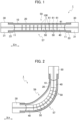
- Fig. 1 is a cross-sectional view along an axial direction XA schematically showing a state before a hydraulic actuator 1 according to the one embodiment contracts/curls.
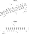
- Fig. 2 is a cross-sectional view schematically showing a state where the hydraulic actuator 1 contracts/curls.
- the hydraulic actuator 1 includes a tube 10 capable of being expanded and contracted by fluid pressure, a sleeve 20 that is a structural member made of woven fiber cords directed in predetermined directions (predetermined weave angle) to exert stretchability and covers an outer circumferential surface of the tube 10, and a pair of sealing members 30 that seal both ends 11 of the tube 10 in an axial direction XA thereof, respectively.
- the hydraulic actuator 1 of the embodiment expands in its radial direction while being restricted by the tension of the fiber cords forming the sleeve 20 and contracts in the axial direction XA of the hydraulic actuator 1.
- the fluid pressure in the tube 10 is decreased, its length in the axial direction XA is restored. This shape change allows the hydraulic actuator 1 to function as an actuator.
- the hydraulic actuator 1 like this is a so-called McKibben-type hydraulic actuator.
- This hydraulic actuator 1 can be suitably used not only for artificial muscles, but also for body limbs (upper limbs, lower limbs and so on) of robots that require higher capacity (contraction force).
- the pair of the sealing members 30 may be provided with a joint portion (not shown in the drawings) or the like to be connected with a member or the like to be jointed.
- plural inner pieces 40, 50 arranged adjacent to each other in the axial direction XA inside the tube 10 are provided as members for curling the hydraulic actuator by restraining its compression in the axial direction XA.
- the phrase "restraining" the compression of the hydraulic actuator in the axial direction XA can be rephrased as regulating or restricting the compression of the hydraulic actuator in the axial direction XA.
- the inner pieces 40 located at both ends of the plural inner pieces 40, 50 in the axial direction XA are fixed to sealing members 30 provide as a pair, respectively. Then, the plural inner pieces 40, 50 are arranged between the paired sealing members 30.
- the plural inner pieces 40, 50 are configured to include a restraint side 57 where the adjacent inner pieces 40, 50 are in contact with each other in the tube 10 whose inside is not pressurized by fluid pressure, and a swing side 59 where a gap 61 is made at an opposed position to the restraint side 57 to allow the adjacent inner pieces 40, 50 to swing with respect to each other.
- the adjacent inner pieces 40, 50 are in contact with each other on the restraint side 57 even within the tube 10 in the state not pressurized by the fluid pressure. Therefore, the plural inner pieces 40, 50 resist the compression by the tube 10 applied between the sealing members 30. As a result, the contraction of the tube 10 along the axial direction XA is inhibited on the restraint side 57. At the same time, the tube 10 can contract in the axial direction XA on the swing side 59 until the adjacent inner pieces 40, 50 contact each other and the gaps 61 are decreased. Therefore, the length of the tube 10 on the swing side 59 is relatively shorter than the length of the tube 10 on the restraint side 57. This state is shown in Fig.
- the hydraulic actuator 1 of the present embodiment can be deformed from the state in which it extends along the axial direction XA before the pressurization shown in Fig. 1 to the curled state in which it curls to the swing side 59.
- the state in which the gaps 61 are decreased includes not only a state in which the gaps 61 are fully closed but also a state in which the gaps 61 are narrowed.
- Fluid used to actuate the hydraulic actuator 1 may be either a gas, such as air, or a liquid, such as water or mineral oil.
- the hydraulic actuator 1 can have high durability to withstand hydraulic actuation with high pressure on the tube 10 and sleeve 20.
- each of the sealing members 30 seals the both ends 11 of the tube 10 in the axial direction XA.
- each of the sealing members 30 includes a sealing member main body 31 and a crimp member 33.
- the sealing member main body 31 seals the end 11 of the tube 10 in the axial direction XA.
- the crimp member 33 crimps the tube 10 and the sleeve 20 together with the sealing member main body 31. It is acceptable that press marks, which are marks made when the crimp member 33 is crimped by a jig, are formed on the outer circumferential surface of the crimp member 33.
- the sealing member main body 31 of at least one sealing member 30 of the pair of the sealing members 30 is provided with a connection port to which a hose (conduit) connected to an actuation pressure source of the hydraulic actuator 1 is attached.
- the fluid pressure inside the tube 10 is controlled by the fluid that flows into and out of the hydraulic actuator 1 via a fluid passage that is connected to this connection port, and the tube 10 of the hydraulic actuator 1 expands and contracts.
- the driving pressure source of the hydraulic actuator 1 is, for example, a gas or liquid compressor.
- the hydraulic actuator 1 is configured of the tube 10, the sleeve 20, the pair of the sealing members 30, and the plural inner pieces 40, 50, as described above.
- the tube 10 is a hollow cylindrical tube that is expanded or contracted by the fluid pressure.
- the tube 10 is made from an elastic material such as butyl rubber because of repeated expansion and contraction by the fluid.
- the elastic material is NBR (nitrile rubber) with high oil resistance, or is at least one material selected from a group consisting of hydrogenated NBR, chloroprene rubber, and epichlorohydrin rubber.
- the sleeve 20 has a hollow cylindrical shape and covers the outer circumferential surface of the tube 10 in the hydraulic actuator 1.
- the sleeve 20 is a structural member made of woven fiber cords directed in predetermined directions relative to the axial direction XA of the tube 10 (axial direction of the hydraulic actuator 1) whose inside pressure is not yet increased to exert stretchability.
- the fiber cords are woven to have a structure in which the directed fiber cords form a repetitive-rhombic pattern by being crossed each other. By having such a pattern, the sleeve 20 deforms in a pantograph manner and follows the expansion and contraction of the tube 10 while regulating the expansion and contraction.
- the sleeve 20, which is crimped onto the sealing members 30 together with the tube 10 is actuated so that the weave angle of the woven fiber cords converges to 54.7 degrees when the hydraulic actuator 1 is actuated. Therefore, in a case where the weave angle before the hydraulic actuator 1 is actuated is smaller than 54.7 degrees, the hydraulic actuator 1 gets shrunk in the axial direction. And, in a case where the weave angle is greater than 54.7 degrees, the hydraulic actuator 1 gets elongated in the axial direction.
- the sleeve 20 used in the present embodiment is woven so that the directions of the fiber cords of the sleeve 20 before the expansion and contraction form the predetermined weave angle greater than 54.7 degrees relative to the axial direction XA of the hydraulic actuator 1 before pressure is applied thereto.
- the directions of the fiber cords which regulate the deformation of the tube 10 due to changes of its internal fluid pressure, are oriented so as to be the predetermined directions (predetermined weave angle) by which the hydraulic actuator 1 gets shortened when the tube 10 is expanded.
- the fiber cords are woven into the sleeve 20 so that the weave angle becomes 15 degrees to 40 degrees.
- the hydraulic actuator 1 using this sleeve 20 is actuated so as to be shortened, because the weave angle of the sleeve 20 becomes larger than the pre-shortening weave angle (gets closer to 54.7 degrees) at the increase of the fluid pressure in the tube 10.
- Aromatic polyamide (aramid fiber) or polyethylene terephthalate (PET) fiber cords are preferred as the fiber cords that configures the sleeve 20. However, they are not limited to these types of fiber cords, but may also be made of high-strength fiber cords such as PBO fiber (poly-paraphenylene benzobisoxazole), for example.
- PBO fiber poly-paraphenylene benzobisoxazole
- the plural inner pieces 40, 50 are aligned in the axial direction XA inside the tube 10 so as to be adjacent to each other as shown in Fig. 1 .
- the inner pieces 40 disposed at both ends in the axial direction XA, among the plural inner pieces 40, 50, are fixed to the paired sealing members 30, respectively.
- the plural inner pieces 40, 50 are configured such that, in the tube 10 before the pressurization, the adjacent inner pieces 40, 50 are in contact with each other on one side perpendicular to the axial direction XA (on the restraint side 57) and the gaps 61 are made on an opposite side to the one side (on the swing side 59) so as to allow the adjacent inner pieces 40, 50 to swing with respect to each other.
- the plural inner pieces 40, 50 are aligned inside the tube 10 in a state before the pressurization of the hydraulic actuator 1, with the number of the inner pieces 40, 50 corresponding to the length of the hydraulic actuator 1 in the axial direction XA. Specifically, the plural inner pieces 40, 50 are aligned so that the adjacent inner pieces are surely in contact with each other on the restraint side 57 from the one of the sealing members 30 to the other of the sealing member 30. If the length of the tube 10 in the axial direction XA is short, the plural inner pieces may be formed with only the two inner pieces 40.
- the inner piece 50 which is adjacent to only one of the paired inner pieces 40 fixed to the paired sealing members 30, or not adjacent to any of the paired inner pieces 40, may be omitted.
- the length of the tube 10 in the axial direction XA is long, the number of the inner pieces 50 located between the inner pieces 40 may be increased or the length of the inner pieces 50 may be changed to get the inner pieces contacted with each other on the restraint side 57.
- the material of the plural inner pieces 40, 50 may be selected from materials that provide compressive stiffness enough not to be deformed when the hydraulic actuator 1 is actuated so as to be shortened in the axial direction XA by the increase of the fluid pressure in the tube 10, especially not to be deformed by compressive stress applied thereto on the restraint side 57.
- the material of the plural inner pieces 40, 50 may be resin such as thermoplastic synthetic resin, a hard plastic, or a hard foam material such as hard foam synthetic resin.
- the material of the plural inner pieces 40, 50 may be metal such as stainless steel. If it is desired to make the hydraulic actuator 1 lighter, it is preferable to make it of resin, a hard plastic, or a hard foam material.
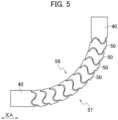
- Fig. 3 is a perspective view showing a state in which the plural inner pieces 40, 50 arranged inside the hydraulic actuator 1 are in contact with each other so as to be capable of being aligned in the hydraulic actuator 1 before it curls.
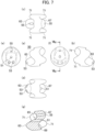
- Fig. 4 is a side view of the plural inner pieces 40, 50 in the state shown in Fig 3 .
- Fig. 5 is a side view showing a state in which the plural inner pieces 40, 50 are in the curled state and in contact with each other.
- Fig. 6 shows perspective views of the inner piece 50 that is not directly fixed to the sealing member 30 among the plural inner pieces 40, 50.
- Fig. 6(a) is a perspective view mainly showing a left side of the inner piece in Fig. 4 .
- FIG. 6(b) is a perspective view mainly showing of a right side of the inner piece in Fig. 4 .
- Figs. 7(a)-7(f) show a six-view drawing of the inner pieces 50 that is not directly fixed to the sealing member 30 among the plural inner pieces 40, 50.
- Fig. 7(g) is a cross-sectional view taken along a line VIIg-VIIg in Fig. 7(f) .
- the six-view drawing in Figs 7(a)-7(f) includes a front view in Fig. 7(a) , a rear view in Fig. 7(b) , a plan view in Fig. 7(c) , a bottom view in Fig. 7(d) , a left side view in Fig. 7(e) , and a right side view in Fig. 7(f) .
- Figs. 3 and 4 show the state in which the plural inner pieces 40, 50 are aligned in the tube 10 of the hydraulic actuator 1 before the pressurization of the tube 10 (the state before the hydraulic actuator 1 curls, the state shown in the schematic view in Fig. 1 ).
- the inner pieces 40, 50 are aligned so that the adjacent inner pieces are in contact with each other on the restraint side 57 and the gaps 61 are formed on the swing side 59.
- the plural inner pieces 40, 50 form an almost cylindrical shape with the axial direction XA as its axis so as to match the shape of the interior space of the tube 10 in a state where they are adjacent to each other.
- Fig. 5 shows the state of the plural inner pieces 40, 50 aligned in the tube 10 of the hydraulic actuator 1 after the tube 10 is pressurized (the state after the hydraulic actuator 1 is curled, the state shown in the schematic view in Fig. 2 ).
- the plural inner pieces 40, 50 are curled until there is no gap 61 on the swing side 59, or the gaps 61 become narrower, while the contact state on the restraint side 57 is maintained.
- a first convex portion 63 is formed on the restraint side 57 (a lower side in Fig. 7(a) ) and a first concave portion 65 is formed on the swing side 59 (an upper side in Fig. 7(a) ).
- a second convex portion 67 is formed on the swing side 59 and a second concave portion 69 is formed on the restraint side 57.
- the first convex portion 63 of one inner piece 50 enters the second concave portion 69 of the other inner piece 50 and contacts the second concave portion 69.
- the second convex portion 67 of the other inner piece 50 enters the first concave portion 65 of the one inner piece 50, but does not contact the first concave portion 65 to form the gap 61.
- the protrusion of the first convex portion 63 in the axial direction XA is greater than the depression of the second concave portion 69, so that the adjacent inner pieces 50 contact each other on the restraint side 57.
- the gap 61 is formed between the adjacent inner pieces 50 on the swing side 59, because the protrusion of the second convex portion 67 in the axial direction XA is less than the depression of the first concave portion 65.
- side walls 71 which protrude in the axial direction XA from both side portions of a position where the first concave portion 65 or the second concave portion 69 is formed, respectively, are formed on both sides of the middle portion where the first convex portion 63, the first concave portion 65, the second convex portion 67 and second concave portion 69 are formed.
- Fig. 7(b), 7(c), 7(g) and so on on the restraint side 57 or the swing side 59, side walls 71, which protrude in the axial direction XA from both side portions of a position where the first concave portion 65 or the second concave portion 69 is formed, respectively, are formed on both sides of the middle portion where the first convex portion 63, the first concave portion 65, the second convex portion 67 and second concave portion 69 are formed.
- Fig. 7(b), 7(c), 7(g) and so on the restraint side 57 or the swing side 59 side
- the side walls 71 restrain relative motions, such as rotations about the axial direction XA, of the adjacent inner pieces 40, 50 in the tube 10.
- the side walls 71 also prevent the hydraulic actuator 1 from curling in a direction other than the curling direction by contacting the adjacent first convex portion 63 or the adjacent second convex portion 67, even when stress perpendicular to the axial direction XA is applied to the hydraulic actuator 1.
- the side walls 71 are formed to have a protrusion that does not interfere with the swinging of the inner piece 50 or the curling of the hydraulic actuator 1.
- a vent hole 51 is formed in the inner piece 50 so as to penetrate the center of its circular outer circumference.
- two first through holes 53 are formed on the restraint side 57 and a second through hole 55 is formed on the swing side 59.
- Each one end of the first through holes 53 is opened on the first convex portion 63 as shown in Figs. 6(a) , 7(a), 7(b) and 7(d) and each other end thereof is opened in the second concave portion 69 as shown in Fig. 6(b) .
- one end of the second through hole 55 is opened in the first concave portion 65 as shown in Figs. 6(a) and 7(g) , and the other end thereof is opened on the second convex portion 67 as shown in Figs. 6(b) , 7(c) and 7(g) .
- Fig. 8 shows a cross-sectional view of the hydraulic actuator 1 according to the present embodiment in its contracted and curled state with restraint fiber cords 80 for keeping the inner pieces 40, 50 in contact with each other on the restraint side 57 and an anti-reverse-curling cord 90 located on the swing side 59.
- a vent hole 41 through which the fluid can flow in and out of the sealing member 30 is formed in each of the inner pieces 40 that are configured to be placed at both ends of the axial direction XA and fixed to the paired sealing members 30, respectively.
- two first through holes 43 are formed on the restraint side 57 and one second through hole 45 is formed on the swing side 59.
- the end of the second through hole 45 closer to the sealing member 30 is opened in a notch (locator portion) 47 formed at a portion of the inner piece 40 that is on the swing side 59 and closer to the sealing member 30.
- the notch 47 also functions as an eye mark that clearly indicates the swing side 59 toward which the inner pieces 40, 50 are capable of curling.
- a rubber cushion member 100 is disposed in each gap 61 formed on the swing side between the adjacent inner pieces 40, 50.
- the cushion member 100 is a member that can be compressed so that the swinging of the inner pieces 40, 50 is not significantly restricted during the curling deformation of the hydraulic actuator 1, and that restores the inner pieces 40, 50 to their pre-pressurized posture as shown in Fig. 1 when the inside of the tube 10 of the hydraulic actuator 1 is depressurized.
- the cushion member 100 is suitably made of rubber, urethane foam, or other material that exhibits the desired compressibility that does not significantly restrict the swinging of the inner pieces 40, 50 during the curling deformation of the hydraulic actuator 1 and good restorative properties that can restore the inner pieces 40, 50 to their pre-pressure state against repeated compression deformation.
- a clearance may be provided, in consideration of the shape of the compressed and deformed cushion member 100, in the gap 61 where the cushion member 100 is placed so that the curling deformation of the inner pieces 40, 50 is not inhibited when the cushion member 100 is deformed.
- the inner piece 40 can be secured to the sealing member 30 in any manner, as long as it is secured to the sealing member 30 in a state where the vent hole 41 is kept passed through without preventing the fluid from flowing through the sealing member 30.
- a recess in the axial direction XA that can fit into the outer circumference of the sealing member 30 may be formed at the axial end of the inner piece 40.
- the fluid passage of the sealing member 30 may be formed with a larger diameter than that required as a flow path, and a protruding portion in the axial direction XA may be formed on the inner piece 40 to fit into the inner circumference of the fluid passage of the sealing member 30.
- the vent hole 41 of the inner piece 40 is essential for allowing fluid to flow in and out of the sealing member 30.
- the vent hole 51 of the inner piece 50 do not have to be formed in the inner piece 50 because fluid can flow in and out of the tube 10 from the position where the inner piece 40 and the inner piece 50 are adjacent to each other.
- the sealing member(s) 30 seals the end 11 of the tube 10 in the axial direction XA of the hydraulic actuator 1.
- the sealing member 30 is configured of a sealing member main body 31 and a crimp member 33.
- the sealing member main body 31 is inserted into the tubular tube 10. Specifically, the sealing member main body 31 has a head whose diameter is larger than the inner diameter of the tube 10 and a stem having an outer diameter that can be inserted into the inner diameter of the tube 10. The stem is inserted into the tube 10.
- a metal such as stainless steel may be suitably used as the sealing member main body 31, but it is not limited to such a metal.
- a hard plastic material may be used as the sealing member main body 31.
- the crimp member(s) 33 crimps the tube 10 into which the sealing member main body 31 is inserted and the sleeve 20 covering the outer circumferential surface of the tube 10 together with the sealing member main body 31.
- the crimp member 33 is provided around the circumference of the portion where the sealing member main body 31 is inserted into the tube 10 and the sleeve 20, and crimps these members 10 and 20 onto the sealing member main body 31.
- the crimp member 33 Metals such as aluminum alloys, brass, and iron can be used for the crimp member 33.
- the press marks may be formed on the crimp member 33.
- sealing member(s) 30 may be provided with an engagement ring (not shown) for engaging the sleeve 20 with the sealing member main body 31.
- the sleeve 20 may be folded radially outwardly via the engagement ring.
- a shape of the engagement ring may be a shape that can be engaged with the sealing member main body 31.
- a material such as metal or hard plastic similar to that of the sealing member main body 31, or a material such as natural fibers (natural fiber threads) or rubber (e.g., O-ring) can be used for a material of the engagement ring.
- the plural inner pieces 40, 50 further include a restraint mechanism 43, 53, 80 that keeps the adjacent plural inner pieces 40, 50 in contact with each other on the restraint side 57 in the tube 10 whose inside is pressurized by the fluid pressure.
- the first through holes 43 of the inner piece 40 and the first through holes 53 of the inner piece 50, or the opposing first through holes 53 are formed to be communicated with each other in a state where they are adjacent to each other.
- the second through hole 45 of the inner piece 40 and the second through hole 55 of the inner piece 50, or the opposing second through holes 55 are similarly formed to be communicated with each other in a state where they are adjacent to each other.
- the restraint mechanism 43, 53, 80 includes the first through holes 43, 53 formed in each of the inner pieces 40, 50 so as to be communicated with each other on the restraint side 57 between the adjacent inner pieces 40, 50 or the adjacent inner pieces 50, and the restraint fiber cords 80 that is inserted through the first through holes 43, 53 from one end to the other end of the plural inner pieces 40, 50 in the axial direction XA to keep the inner pieces 40, 50 in contact with each other on the restraint side 57.
- the plural first through holes 43, 53 of the restraint mechanism may be formed in each of the inner pieces 40, 50.
- the two first through holes 43, 53 are formed in each of the inner pieces 40, 50, as shown in Figs. 6(a), 6(b) and so on.
- Each of the plural first through holes 43, 53 is communicated with each other from the one end to the other end of the plural inner pieces 40, 50 in the axial direction XA, and the restraint fiber cords 80 are inserted through each path of the first through holes 43, 53.
- the two restraint fiber cords 80 are inserted from the one end to the other end of the plural inner pieces 40, 50 in the axial direction XA.
- Each end of the restraint fiber cords 80 has a structure such that it does not enter into the interior of the first through hole 43 while the restraint fiber cords 80 extend through the first through holes 43, 53.
- each end of the restraint fiber cords 80 has a larger diameter than an inner diameter of the first through hole 43.
- the restraint fiber cords 80 restrain the relative motion of the adjacent inner pieces 40, 50 while being extended through the first through holes 43, 53. Furthermore, due to the restriction by the two restraint fiber cords 80, the relative motion, such as rotation between the adjacent inner pieces 40, 50 in the tube 10, can be restrained.
- the material of the restraint fiber cords 80 may be selected from among fiber cords that can be used for fiber cords of the sleeve 20 in consideration of the desired tensile strength or the like.
- the second through holes 45, 55 are communicated with each other from the one end to the other of the plural inner pieces 40, 50 in the axial direction XA.
- An anti-reverse-curling cord 90 for restricting the gaps 61 on the swing side 59 from widening from their state before the pressurization by the fluid pressure is extended through the second through holes 45, 55.
- the anti-reverse-curling cord 90 has a length equivalent to the distance between the openings of the second through holes 45 in the notches 47 formed on the swing side 59 of the inner pieces 40 placed at both ends in the non-curling state shown in Figs 3, 4 and so on, and its each end has a structure such that it does not enter into the interior of the second through hole 45, as shown in Fig. 8 .
- each end of the anti-reverse-curling cord 90 has a larger diameter than an inner diameter of the second through hole 45.
- each end of the anti-reverse-curling cord 90 is distanced from the opening of the second through hole 45 in the notch 47, that is, no tensile tension is generated in the anti-reverse-curling cord 90. If the hydraulic actuator 1 curls in a direction from its expanded state such that the gaps 61 on the swing side 59 are widened from its state before the pressurization by the fluid pressure, each end of the anti-reverse-curling cord 90 contacts the opening of the second through hole 45 in the notch 47 to generate tensile tension in the anti-reverse-curling cord 90, and thereby the reverse-curling of the hydraulic actuator 1 is prevented.
- the material of the anti-reverse-curling cord 90 may be selected from among fiber cords that can be used for fiber cords of the sleeve 20 in consideration of the desired tensile strength or the like.
- the stem of the sealing member main body 31 of the sealing member 30 is inserted into the tube 10.
- the tube 10 and the sleeve 20 covering the outer circumferential surface of the tube 10 are crimped onto the sealing member main body 31 by the crimp member 33.
- the crimp member 33 is larger than the outer diameter of the stem of the sealing member main body 31, and then crimped by a jig after the stem is inserted into it.
- the crimp member 33 crimps the tube 10 and the sleeve 20 together with the sealing member main body 31.
- the hydraulic actuator 1 has the following features.
- the hydraulic actuator 1 according to the present embodiment can be curled to a predetermined curled shape based on the structure of the inner pieces 40, 50, which restrict the expansion and contraction of the tube 10. Therefore, the hydraulic actuator 1 does not excessively curl beyond the predetermined curved shape, even when the pressure in the tube 10 increases excessively.
- the hydraulic actuator 1 even when the hydraulic actuator 1 is repeatedly curled, the inner pieces 40, 50 are not deformed, because the hydraulic actuator 1 is curled by providing the restraint side 57 and the swing side 59 on the inner pieces 40, 50 that are made of a material with compressive rigidity. Therefore, the hydraulic actuator 1 has high repeat durability because the restoring force to the state before curling is hardly decreased even after being curled repeatedly.
- the relative motion between the adjacent inner pieces 40, 50 is restrained by the restraint mechanisms 43, 53, 80.
- the curling structure of the hydraulic actuator 1 can be maintained, even when the pressure in the tube 10 is excessively increased and tensile stress is applied between the sealing members 30.
- the tube 10 is sealed by the sealing members 30 with the inner pieces 40, 50 disposed therein. Therefore, the volume in the tube 10 becomes smaller than the volume in the tube 10 when the inner pieces 40, 50 are not disposed therein.
- the smaller volume in the tube 10 allows the pressure in the tube to increase more easily in the hydraulic actuator 1 according to the present embodiment than in a case where the inner pieces 40, 50 are not used, and thereby the response speed of the hydraulic actuator 1 can be improved.
- the plural inner pieces 40, 50 aligned inside the hydraulic actuator 1 as shown in Figs. 3 and 4 are in a state they are adjacent to and in contact with each other to form an almost cylindrical shape with the axial direction XA as its axis. Then, the restraint side 57 where the adjacent inner pieces 40, 50 are in contact with each other is always located on a first side circumferentially with respect to the tube 10. Furthermore, the swing side 59 is located on a second side opposite to the first side.
- locations of the restraint side 57 and the swing side 59 in the plural inner pieces 40, 50 arranged inside the hydraulic actuator 1 with respect to the tube 10 is not limited to the above locations.
- Each of the restraint side 57 and the swing side 59 in the plural inner pieces 40, 50 needs not always be located on the same side with respect to the tube 10, and the locations of the restraint side 57 and the swing side 59 with respect to the tube 10 may be interchangeable.
- the restraint side 57 is located on the first side and the swing side 59 is located on the second side in a section from one end to a predetermined position in the axial direction XA of the tube 10 and the restraint side 57 is located on the second side and the swing side 59 is located on the first side in the other section from the above-mentioned predetermined position to the other end, so that the deformation of the tube 10 during curling may be S-shaped.
- adopted may be a configuration where the inner pieces 50 are arranged as follows: the first convex portion 63 and the first concave portion 65 is kept unchanged on the left side; the second convex portion 67 is formed at the location of the second concave portion 69 and the second concave portion 69 is formed at the location of the second convex portion 67 on the right side; the first through hole 53 penetrates through each inner piece so as to connect the first convex portion 63 with the second concave portion 69; and the second through hole 55 penetrates through each inner piece so as to connect the first concave portion 65 with the second convex portion 67.
- the cushion member 100 is made of rubber, urethane foam or the like in the present embodiment, but the cushion member 100 is not limited to these.
- a member that can ensure the curling of the hydraulic actuator 1 by being easily compressible and deformable when the inside of the tube 10 is pressurized, and that can restore the posture of the inner pieces 40, 50 to its pre-pressurized state when the inside of the tube 10 is depressurized should be selected.
- a spring with an elastic modulus satisfying the above conditions may be placed in the gap 61 as the cushion member 100. If the largest possible amount of curling is required, the cushion member 100 may be omitted from the configuration.
Landscapes
- Engineering & Computer Science (AREA)
- Chemical & Material Sciences (AREA)
- Analytical Chemistry (AREA)
- Physics & Mathematics (AREA)
- Fluid Mechanics (AREA)
- Mechanical Engineering (AREA)
- General Engineering & Computer Science (AREA)
- Actuator (AREA)
Abstract
Description
- The present invention relates to a hydraulic actuator, especially to a so-called McKibben-type hydraulic actuator.
- Conventionally, as a hydraulic actuator that expands and contracts a tube using gas or liquid, widely used is a (so-called McKibben-type) structure with a rubber tube that expands and contracts by air pressure and a sleeve that covers the outer surface of the tube.
- Also known is a McKibben-type hydraulic actuator in which its tube and its sleeve are curled during contraction from an axially-extending state (see Patent Literature 1). Specifically, a hydraulic actuator is known that has a leaf spring provided inside the sleeve of the hydraulic actuator from one end to the other end in the axial direction, and can be curled by the action of the leaf spring. In such a McKibben-type hydraulic actuator to be curled, excessive curling of the hydraulic actuator, which may occur when the fluid pressure increases, is suppressed by limiting the curling of the tube by weave angle of the sleeve.
- [Patent Literature 1]
Japanese Patent Laid-Open Publication No. 2021-88999 - However, a conventional curling-type hydraulic actuator may be subject to gradual plastic deformation when its leaf spring for curling the hydraulic actuator is curled repeatedly, and thus it is concerned that its restoring force will reduce.
- An object of the present invention is to provide a hydraulic actuator, capable of curling, that can prevent excessive curling potentially caused by increasing of a fluid pressure in the hydraulic actuator, and whose restoring force to a pre-curling state hardly reduces even when it curls repeatedly, i.e., that has high repeat durability.
- A hydraulic actuator according to embodiments of the present invention includes a tube capable of being expanded and contracted by fluid pressure, a sleeve that is a structural member made of woven fiber cords directed in predetermined directions to exert stretchability and covers an outer circumferential surface of the tube, a pair of sealing members that seal both ends of the tube in an axial direction thereof, respectively, and plural inner pieces that are aligned inside the tube so as to be adjacent to each other. The plural inner pieces are configured to include a restraint side where adjacent inner pieces are in contact with each other in the tube whose inside is not pressurized by the fluid pressure and a swing side where a gap is made at an opposed position to the restraint side to allow the adjacent inner pieces to swing with respect to each other. The plural inner pieces further include a restraint mechanism that keeps the adjacent inner pieces in contact with each other on the restraint side in the tube whose inside is pressurized by the fluid pressure.
- According to the above configuration, it is possible to provide a hydraulic actuator, capable of curling, that can prevent excessive curling potentially caused by increasing of a fluid pressure in the hydraulic actuator, and whose restoring force to a pre-curling state hardly reduces even when it curls repeatedly, i.e., that has high repeat durability.
-
- [
Fig. 1] Fig. 1 is a cross-sectional view along an axial direction schematically showing a state before a hydraulic actuator according to one embodiment contracts/curls. - [
Fig. 2] Fig. 2 is a cross-sectional view schematically showing a state where the hydraulic actuator contracts/curls. - [
Fig. 3] Fig. 3 is a perspective view showing a state where plural inner pieces get contact with each other that are aligned in the hydraulic actuator. - [
Fig. 4] Fig. 4 is a side view showing a state of the plural inner pieces before the hydraulic actuator curls. - [
Fig. 5] Fig. 5 is a side view showing a state of the plural inner pieces after the hydraulic actuator curls. - [
Fig. 6] Fig. 6 shows perspective views of an inner piece that is not directly fixed to a sealing member among the plural inner pieces;Fig. 6(a) is a perspective view mainly showing a left side of the inner piece inFig. 4 , andFig. 6(b) is a perspective view mainly showing a right side of the inner piece inFig. 4 . - [
Fig. 7] Fig. 7 shows a six-view drawing and a cross-sectional view, taken along a vertically-extending centerline in a side view, of the inner piece that is not directly fixed to the sealing members among the plural inner pieces;Fig. 7(a) is a front view,Fig. 7(b) is a rear view,Fig. 7(c) is a plan view,Fig. 7(d) is a bottom view,Fig. 7(e) is a left side view,Fig. 7(f) is a right side view, andFig. 7(g) is the cross-sectional view taken along a line VIIg- VIIg inFig. 7(f) . - [
Fig. 8] Fig. 8 shows a cross-sectional view of the hydraulic actuator according to the present embodiment in its contracted and curled state with a restraint fiber cord for keeping the inner pieces in contact with each other on a restraint side and an anti-reverse-curling cord located on a swing side. - Hereinafter, one embodiment will be described based on the drawings. Note that the same functions and structures are denoted by the same or similar reference signs, and their description will be omitted accordingly.
-
Fig. 1 is a cross-sectional view along an axial direction XA schematically showing a state before ahydraulic actuator 1 according to the one embodiment contracts/curls.Fig. 2 is a cross-sectional view schematically showing a state where thehydraulic actuator 1 contracts/curls. - As shown in
Fig. 1 , thehydraulic actuator 1 includes atube 10 capable of being expanded and contracted by fluid pressure, asleeve 20 that is a structural member made of woven fiber cords directed in predetermined directions (predetermined weave angle) to exert stretchability and covers an outer circumferential surface of thetube 10, and a pair ofsealing members 30 that seal bothends 11 of thetube 10 in an axial direction XA thereof, respectively. - As a basic characteristic, when the fluid pressure in the
tube 10 is increased, thehydraulic actuator 1 of the embodiment expands in its radial direction while being restricted by the tension of the fiber cords forming thesleeve 20 and contracts in the axial direction XA of thehydraulic actuator 1. When the fluid pressure in thetube 10 is decreased, its length in the axial direction XA is restored. This shape change allows thehydraulic actuator 1 to function as an actuator. - The
hydraulic actuator 1 like this is a so-called McKibben-type hydraulic actuator. Thishydraulic actuator 1 can be suitably used not only for artificial muscles, but also for body limbs (upper limbs, lower limbs and so on) of robots that require higher capacity (contraction force). The pair of the sealingmembers 30 may be provided with a joint portion (not shown in the drawings) or the like to be connected with a member or the like to be jointed. - In the present embodiment, while using a McKibben-type hydraulic actuator having such basic characteristics, plural
inner pieces tube 10 are provided as members for curling the hydraulic actuator by restraining its compression in the axial direction XA. The phrase "restraining" the compression of the hydraulic actuator in the axial direction XA can be rephrased as regulating or restricting the compression of the hydraulic actuator in the axial direction XA. - As shown in
Fig. 1 , theinner pieces 40 located at both ends of the pluralinner pieces members 30 provide as a pair, respectively. Then, the pluralinner pieces members 30. In addition, as shown inFig. 1 , the pluralinner pieces restraint side 57 where the adjacentinner pieces tube 10 whose inside is not pressurized by fluid pressure, and aswing side 59 where agap 61 is made at an opposed position to therestraint side 57 to allow the adjacentinner pieces - With respect to the plural
inner pieces inner pieces restraint side 57 even within thetube 10 in the state not pressurized by the fluid pressure. Therefore, the pluralinner pieces tube 10 applied between the sealingmembers 30. As a result, the contraction of thetube 10 along the axial direction XA is inhibited on therestraint side 57. At the same time, thetube 10 can contract in the axial direction XA on theswing side 59 until the adjacentinner pieces gaps 61 are decreased. Therefore, the length of thetube 10 on theswing side 59 is relatively shorter than the length of thetube 10 on therestraint side 57. This state is shown inFig. 2 , where thehydraulic actuator 1 of the present embodiment can be deformed from the state in which it extends along the axial direction XA before the pressurization shown inFig. 1 to the curled state in which it curls to theswing side 59. Note that the state in which thegaps 61 are decreased includes not only a state in which thegaps 61 are fully closed but also a state in which thegaps 61 are narrowed. - Fluid used to actuate the
hydraulic actuator 1 may be either a gas, such as air, or a liquid, such as water or mineral oil. Thehydraulic actuator 1 can have high durability to withstand hydraulic actuation with high pressure on thetube 10 andsleeve 20. - The pair of sealing
members 30 seals the bothends 11 of thetube 10 in the axial direction XA. Specifically, each of the sealingmembers 30 includes a sealing membermain body 31 and acrimp member 33. The sealing membermain body 31 seals theend 11 of thetube 10 in the axial direction XA. Thecrimp member 33 crimps thetube 10 and thesleeve 20 together with the sealing membermain body 31. It is acceptable that press marks, which are marks made when thecrimp member 33 is crimped by a jig, are formed on the outer circumferential surface of thecrimp member 33. - The sealing member
main body 31 of at least one sealingmember 30 of the pair of the sealingmembers 30 is provided with a connection port to which a hose (conduit) connected to an actuation pressure source of thehydraulic actuator 1 is attached. The fluid pressure inside thetube 10 is controlled by the fluid that flows into and out of thehydraulic actuator 1 via a fluid passage that is connected to this connection port, and thetube 10 of thehydraulic actuator 1 expands and contracts. Not that the driving pressure source of thehydraulic actuator 1 is, for example, a gas or liquid compressor. - As shown in
Fig. 1 , thehydraulic actuator 1 is configured of thetube 10, thesleeve 20, the pair of the sealingmembers 30, and the pluralinner pieces - The
tube 10 is a hollow cylindrical tube that is expanded or contracted by the fluid pressure. Thetube 10 is made from an elastic material such as butyl rubber because of repeated expansion and contraction by the fluid. When thehydraulic actuator 1 is actuated hydraulically, it is preferable that the elastic material is NBR (nitrile rubber) with high oil resistance, or is at least one material selected from a group consisting of hydrogenated NBR, chloroprene rubber, and epichlorohydrin rubber. - The
sleeve 20 has a hollow cylindrical shape and covers the outer circumferential surface of thetube 10 in thehydraulic actuator 1. Thesleeve 20 is a structural member made of woven fiber cords directed in predetermined directions relative to the axial direction XA of the tube 10 (axial direction of the hydraulic actuator 1) whose inside pressure is not yet increased to exert stretchability. The fiber cords are woven to have a structure in which the directed fiber cords form a repetitive-rhombic pattern by being crossed each other. By having such a pattern, thesleeve 20 deforms in a pantograph manner and follows the expansion and contraction of thetube 10 while regulating the expansion and contraction. - Note that, in the McKibben-type
hydraulic actuator 1, thesleeve 20, which is crimped onto the sealingmembers 30 together with thetube 10, is actuated so that the weave angle of the woven fiber cords converges to 54.7 degrees when thehydraulic actuator 1 is actuated. Therefore, in a case where the weave angle before thehydraulic actuator 1 is actuated is smaller than 54.7 degrees, thehydraulic actuator 1 gets shrunk in the axial direction. And, in a case where the weave angle is greater than 54.7 degrees, thehydraulic actuator 1 gets elongated in the axial direction. - The
sleeve 20 used in the present embodiment is woven so that the directions of the fiber cords of thesleeve 20 before the expansion and contraction form the predetermined weave angle greater than 54.7 degrees relative to the axial direction XA of thehydraulic actuator 1 before pressure is applied thereto. In other words, the directions of the fiber cords, which regulate the deformation of thetube 10 due to changes of its internal fluid pressure, are oriented so as to be the predetermined directions (predetermined weave angle) by which thehydraulic actuator 1 gets shortened when thetube 10 is expanded. Specifically, the fiber cords are woven into thesleeve 20 so that the weave angle becomes 15 degrees to 40 degrees. - The
hydraulic actuator 1 using thissleeve 20 is actuated so as to be shortened, because the weave angle of thesleeve 20 becomes larger than the pre-shortening weave angle (gets closer to 54.7 degrees) at the increase of the fluid pressure in thetube 10. - Aromatic polyamide (aramid fiber) or polyethylene terephthalate (PET) fiber cords are preferred as the fiber cords that configures the
sleeve 20. However, they are not limited to these types of fiber cords, but may also be made of high-strength fiber cords such as PBO fiber (poly-paraphenylene benzobisoxazole), for example. - In addition, in the present embodiment, the plural
inner pieces tube 10 so as to be adjacent to each other as shown inFig. 1 . Theinner pieces 40 disposed at both ends in the axial direction XA, among the pluralinner pieces members 30, respectively. The pluralinner pieces tube 10 before the pressurization, the adjacentinner pieces gaps 61 are made on an opposite side to the one side (on the swing side 59) so as to allow the adjacentinner pieces - The plural
inner pieces tube 10 in a state before the pressurization of thehydraulic actuator 1, with the number of theinner pieces hydraulic actuator 1 in the axial direction XA. Specifically, the pluralinner pieces restraint side 57 from the one of the sealingmembers 30 to the other of the sealingmember 30. If the length of thetube 10 in the axial direction XA is short, the plural inner pieces may be formed with only the twoinner pieces 40. In other words, among the plural inner pieces, theinner piece 50, which is adjacent to only one of the pairedinner pieces 40 fixed to the paired sealingmembers 30, or not adjacent to any of the pairedinner pieces 40, may be omitted. In addition, if the length of thetube 10 in the axial direction XA is long, the number of theinner pieces 50 located between theinner pieces 40 may be increased or the length of theinner pieces 50 may be changed to get the inner pieces contacted with each other on therestraint side 57. - The material of the plural
inner pieces hydraulic actuator 1 is actuated so as to be shortened in the axial direction XA by the increase of the fluid pressure in thetube 10, especially not to be deformed by compressive stress applied thereto on therestraint side 57. The material of the pluralinner pieces inner pieces hydraulic actuator 1 lighter, it is preferable to make it of resin, a hard plastic, or a hard foam material. - Specific shapes of the plural
inner pieces Figs. 3 to 7 . -
Fig. 3 is a perspective view showing a state in which the pluralinner pieces hydraulic actuator 1 are in contact with each other so as to be capable of being aligned in thehydraulic actuator 1 before it curls.Fig. 4 is a side view of the pluralinner pieces Fig 3 .Fig. 5 is a side view showing a state in which the pluralinner pieces Fig. 6 shows perspective views of theinner piece 50 that is not directly fixed to the sealingmember 30 among the pluralinner pieces Fig. 6(a) is a perspective view mainly showing a left side of the inner piece inFig. 4 .Fig. 6(b) is a perspective view mainly showing of a right side of the inner piece inFig. 4 .Figs. 7(a)-7(f) show a six-view drawing of theinner pieces 50 that is not directly fixed to the sealingmember 30 among the pluralinner pieces Fig. 7(g) is a cross-sectional view taken along a line VIIg-VIIg inFig. 7(f) . The six-view drawing inFigs 7(a)-7(f) includes a front view inFig. 7(a) , a rear view inFig. 7(b) , a plan view inFig. 7(c) , a bottom view inFig. 7(d) , a left side view inFig. 7(e) , and a right side view inFig. 7(f) . -
Figs. 3 and 4 show the state in which the pluralinner pieces tube 10 of thehydraulic actuator 1 before the pressurization of the tube 10 (the state before thehydraulic actuator 1 curls, the state shown in the schematic view inFig. 1 ). Theinner pieces restraint side 57 and thegaps 61 are formed on theswing side 59. Then, as shown inFigs. 3 and 4 , the pluralinner pieces tube 10 in a state where they are adjacent to each other. -
Fig. 5 shows the state of the pluralinner pieces tube 10 of thehydraulic actuator 1 after thetube 10 is pressurized (the state after thehydraulic actuator 1 is curled, the state shown in the schematic view inFig. 2 ). In this state, with respect to the pluralinner pieces inner pieces gap 61 on theswing side 59, or thegaps 61 become narrower, while the contact state on therestraint side 57 is maintained. - Next, the specific structure of the
inner piece 50 that is not directly fixed to the sealing member 30 (other than the pair of theinner pieces 40 located at both ends) will be described with reference toFigs. 6(a)-6(b) andFigs. 7(a)-7(g) . - As shown in
Figs. 6(a) and7(g) , on the left side face of theinner piece 50 relative to the front view ofFig. 7(a) , a firstconvex portion 63 is formed on the restraint side 57 (a lower side inFig. 7(a) ) and a firstconcave portion 65 is formed on the swing side 59 (an upper side inFig. 7(a) ). As shown inFigs. 6(b) and7(g) , on the right side face of theinner piece 50, a secondconvex portion 67 is formed on theswing side 59 and a secondconcave portion 69 is formed on therestraint side 57. - When the plural
inner pieces 50 are aligned adjacent to each other, on therestraint side 57, the firstconvex portion 63 of oneinner piece 50 enters the secondconcave portion 69 of the otherinner piece 50 and contacts the secondconcave portion 69. On the other hand, on theswing side 59, the secondconvex portion 67 of the otherinner piece 50 enters the firstconcave portion 65 of the oneinner piece 50, but does not contact the firstconcave portion 65 to form thegap 61. In other words, in theinner pieces 50, the protrusion of the firstconvex portion 63 in the axial direction XA is greater than the depression of the secondconcave portion 69, so that the adjacentinner pieces 50 contact each other on therestraint side 57. And, thegap 61 is formed between the adjacentinner pieces 50 on theswing side 59, because the protrusion of the secondconvex portion 67 in the axial direction XA is less than the depression of the firstconcave portion 65. - As shown in
Figs. 7(b), 7(c), 7(g) and so on, on therestraint side 57 or theswing side 59,side walls 71, which protrude in the axial direction XA from both side portions of a position where the firstconcave portion 65 or the secondconcave portion 69 is formed, respectively, are formed on both sides of the middle portion where the firstconvex portion 63, the firstconcave portion 65, the secondconvex portion 67 and secondconcave portion 69 are formed. As shown inFig. 7(g) , with respect to the protruding direction of theside walls 71, theside walls 71 formed besides the firstconcave portion 65 protrude similarly to the firstconvex portion 63, and theside walls 71 formed besides the secondconcave portion 69 protrude similarly to the secondconvex portion 67. - The
side walls 71 restrain relative motions, such as rotations about the axial direction XA, of the adjacentinner pieces tube 10. Theside walls 71 also prevent thehydraulic actuator 1 from curling in a direction other than the curling direction by contacting the adjacent firstconvex portion 63 or the adjacent secondconvex portion 67, even when stress perpendicular to the axial direction XA is applied to thehydraulic actuator 1. Note that, as shown inFig. 7(g) , theside walls 71 are formed to have a protrusion that does not interfere with the swinging of theinner piece 50 or the curling of thehydraulic actuator 1. - As shown in
Figs. 7(e) and 7(f) , avent hole 51 is formed in theinner piece 50 so as to penetrate the center of its circular outer circumference. In addition, two first throughholes 53 are formed on therestraint side 57 and a second throughhole 55 is formed on theswing side 59. - Each one end of the first through
holes 53 is opened on the firstconvex portion 63 as shown inFigs. 6(a) ,7(a), 7(b) and 7(d) and each other end thereof is opened in the secondconcave portion 69 as shown inFig. 6(b) . And one end of the second throughhole 55 is opened in the firstconcave portion 65 as shown inFigs. 6(a) and7(g) , and the other end thereof is opened on the secondconvex portion 67 as shown inFigs. 6(b) ,7(c) and 7(g) . -
Fig. 8 shows a cross-sectional view of thehydraulic actuator 1 according to the present embodiment in its contracted and curled state withrestraint fiber cords 80 for keeping theinner pieces restraint side 57 and an anti-reverse-curlingcord 90 located on theswing side 59. - As shown in
Figs. 1 and8 , avent hole 41 through which the fluid can flow in and out of the sealingmember 30 is formed in each of theinner pieces 40 that are configured to be placed at both ends of the axial direction XA and fixed to the paired sealingmembers 30, respectively. Similarly to theinner piece 50 shown inFigs. 6(a)-6(b) andFigs. 7(a)-7(g) , two first throughholes 43 are formed on therestraint side 57 and one second throughhole 45 is formed on theswing side 59. - In the present embodiment, the end of the second through
hole 45 closer to the sealingmember 30 is opened in a notch (locator portion) 47 formed at a portion of theinner piece 40 that is on theswing side 59 and closer to the sealingmember 30. Thenotch 47 also functions as an eye mark that clearly indicates theswing side 59 toward which theinner pieces - In the present embodiment, as shown in
Fig. 1 , arubber cushion member 100 is disposed in eachgap 61 formed on the swing side between the adjacentinner pieces cushion member 100 is a member that can be compressed so that the swinging of theinner pieces hydraulic actuator 1, and that restores theinner pieces Fig. 1 when the inside of thetube 10 of thehydraulic actuator 1 is depressurized. - The
cushion member 100 is suitably made of rubber, urethane foam, or other material that exhibits the desired compressibility that does not significantly restrict the swinging of theinner pieces hydraulic actuator 1 and good restorative properties that can restore theinner pieces - A clearance may be provided, in consideration of the shape of the compressed and
deformed cushion member 100, in thegap 61 where thecushion member 100 is placed so that the curling deformation of theinner pieces cushion member 100 is deformed. - The
inner piece 40 can be secured to the sealingmember 30 in any manner, as long as it is secured to the sealingmember 30 in a state where thevent hole 41 is kept passed through without preventing the fluid from flowing through the sealingmember 30. - For example, as shown in
Fig. 8 , a recess in the axial direction XA that can fit into the outer circumference of the sealingmember 30 may be formed at the axial end of theinner piece 40. The fluid passage of the sealingmember 30 may be formed with a larger diameter than that required as a flow path, and a protruding portion in the axial direction XA may be formed on theinner piece 40 to fit into the inner circumference of the fluid passage of the sealingmember 30. Note that thevent hole 41 of theinner piece 40 is essential for allowing fluid to flow in and out of the sealingmember 30. However, thevent hole 51 of theinner piece 50 do not have to be formed in theinner piece 50 because fluid can flow in and out of thetube 10 from the position where theinner piece 40 and theinner piece 50 are adjacent to each other. - The sealing member(s) 30 seals the
end 11 of thetube 10 in the axial direction XA of thehydraulic actuator 1. The sealingmember 30 is configured of a sealing membermain body 31 and acrimp member 33. - The sealing member
main body 31 is inserted into thetubular tube 10. Specifically, the sealing membermain body 31 has a head whose diameter is larger than the inner diameter of thetube 10 and a stem having an outer diameter that can be inserted into the inner diameter of thetube 10. The stem is inserted into thetube 10. - A metal such as stainless steel may be suitably used as the sealing member
main body 31, but it is not limited to such a metal. For example, a hard plastic material may be used as the sealing membermain body 31. - The crimp member(s) 33 crimps the
tube 10 into which the sealing membermain body 31 is inserted and thesleeve 20 covering the outer circumferential surface of thetube 10 together with the sealing membermain body 31. Specifically, thecrimp member 33 is provided around the circumference of the portion where the sealing membermain body 31 is inserted into thetube 10 and thesleeve 20, and crimps thesemembers main body 31. - Metals such as aluminum alloys, brass, and iron can be used for the
crimp member 33. When thecrimp member 33 is crimped by a crimping jig, the press marks may be formed on thecrimp member 33. - Note that the sealing member(s) 30 may be provided with an engagement ring (not shown) for engaging the
sleeve 20 with the sealing membermain body 31. Specifically, thesleeve 20 may be folded radially outwardly via the engagement ring. - A shape of the engagement ring may be a shape that can be engaged with the sealing member
main body 31. In addition, a material such as metal or hard plastic similar to that of the sealing membermain body 31, or a material such as natural fibers (natural fiber threads) or rubber (e.g., O-ring) can be used for a material of the engagement ring. - In the
hydraulic actuator 1 according to the present embodiment, the pluralinner pieces restraint mechanism inner pieces restraint side 57 in thetube 10 whose inside is pressurized by the fluid pressure. - The first through
holes 43 of theinner piece 40 and the first throughholes 53 of theinner piece 50, or the opposing first throughholes 53 are formed to be communicated with each other in a state where they are adjacent to each other. The second throughhole 45 of theinner piece 40 and the second throughhole 55 of theinner piece 50, or the opposing second throughholes 55 are similarly formed to be communicated with each other in a state where they are adjacent to each other. - The
restraint mechanism holes inner pieces restraint side 57 between the adjacentinner pieces inner pieces 50, and therestraint fiber cords 80 that is inserted through the first throughholes inner pieces inner pieces restraint side 57. - The plural first through
holes inner pieces holes inner pieces Figs. 6(a), 6(b) and so on. - Each of the plural first through
holes inner pieces restraint fiber cords 80 are inserted through each path of the first throughholes - In the present embodiment, the two
restraint fiber cords 80 are inserted from the one end to the other end of the pluralinner pieces restraint fiber cords 80 has a structure such that it does not enter into the interior of the first throughhole 43 while therestraint fiber cords 80 extend through the first throughholes restraint fiber cords 80 has a larger diameter than an inner diameter of the first throughhole 43. Therestraint fiber cords 80 restrain the relative motion of the adjacentinner pieces holes restraint fiber cords 80, the relative motion, such as rotation between the adjacentinner pieces tube 10, can be restrained. - Note that the material of the
restraint fiber cords 80 may be selected from among fiber cords that can be used for fiber cords of thesleeve 20 in consideration of the desired tensile strength or the like. - On the
swing side 59 where the pluralinner pieces inner pieces holes inner pieces cord 90 for restricting thegaps 61 on theswing side 59 from widening from their state before the pressurization by the fluid pressure is extended through the second throughholes - The anti-reverse-curling
cord 90 has a length equivalent to the distance between the openings of the second throughholes 45 in thenotches 47 formed on theswing side 59 of theinner pieces 40 placed at both ends in the non-curling state shown inFigs 3, 4 and so on, and its each end has a structure such that it does not enter into the interior of the second throughhole 45, as shown inFig. 8 . In other words, each end of the anti-reverse-curlingcord 90 has a larger diameter than an inner diameter of the second throughhole 45. - Note that, when the
hydraulic actuator 1 is curled as shown inFig. 8 , each end of the anti-reverse-curlingcord 90 is distanced from the opening of the second throughhole 45 in thenotch 47, that is, no tensile tension is generated in the anti-reverse-curlingcord 90. If thehydraulic actuator 1 curls in a direction from its expanded state such that thegaps 61 on theswing side 59 are widened from its state before the pressurization by the fluid pressure, each end of the anti-reverse-curlingcord 90 contacts the opening of the second throughhole 45 in thenotch 47 to generate tensile tension in the anti-reverse-curlingcord 90, and thereby the reverse-curling of thehydraulic actuator 1 is prevented. - Note that the material of the anti-reverse-curling
cord 90 may be selected from among fiber cords that can be used for fiber cords of thesleeve 20 in consideration of the desired tensile strength or the like. - As shown in
Figs. 1, 2 and8 , the stem of the sealing membermain body 31 of the sealingmember 30 is inserted into thetube 10. Thetube 10 and thesleeve 20 covering the outer circumferential surface of thetube 10 are crimped onto the sealing membermain body 31 by thecrimp member 33. - The
crimp member 33 is larger than the outer diameter of the stem of the sealing membermain body 31, and then crimped by a jig after the stem is inserted into it. Thecrimp member 33 crimps thetube 10 and thesleeve 20 together with the sealing membermain body 31. - The
hydraulic actuator 1 has the following features. -
- Large curling angle (capable of curling more than 180 degrees)
- Generated Force is large (approx. 40N)
- Easy to control force (generated force is proportional to pressure)
- Simple structure
- Also capable of direct contacting with the manipulation target according to surface coating
- In addition, the
hydraulic actuator 1 according to the present embodiment can be curled to a predetermined curled shape based on the structure of theinner pieces tube 10. Therefore, thehydraulic actuator 1 does not excessively curl beyond the predetermined curved shape, even when the pressure in thetube 10 increases excessively. - In addition, even when the
hydraulic actuator 1 is repeatedly curled, theinner pieces hydraulic actuator 1 is curled by providing therestraint side 57 and theswing side 59 on theinner pieces hydraulic actuator 1 has high repeat durability because the restoring force to the state before curling is hardly decreased even after being curled repeatedly. - In addition, the relative motion between the adjacent
inner pieces restraint mechanisms hydraulic actuator 1 can be maintained, even when the pressure in thetube 10 is excessively increased and tensile stress is applied between the sealingmembers 30. - Furthermore, in the
hydraulic actuator 1, thetube 10 is sealed by the sealingmembers 30 with theinner pieces tube 10 becomes smaller than the volume in thetube 10 when theinner pieces tube 10 allows the pressure in the tube to increase more easily in thehydraulic actuator 1 according to the present embodiment than in a case where theinner pieces hydraulic actuator 1 can be improved. - Although the contents of the present invention have been described in accordance with the above embodiment, it is obvious to those skilled in the art that the present invention is not limited to the descriptions and that various modifications and improvements are possible.
- In the present embodiment, the plural
inner pieces hydraulic actuator 1 as shown inFigs. 3 and 4 are in a state they are adjacent to and in contact with each other to form an almost cylindrical shape with the axial direction XA as its axis. Then, therestraint side 57 where the adjacentinner pieces tube 10. Furthermore, theswing side 59 is located on a second side opposite to the first side. However, locations of therestraint side 57 and theswing side 59 in the pluralinner pieces hydraulic actuator 1 with respect to thetube 10 is not limited to the above locations. - Each of the
restraint side 57 and theswing side 59 in the pluralinner pieces tube 10, and the locations of therestraint side 57 and theswing side 59 with respect to thetube 10 may be interchangeable. - Specifically, the
restraint side 57 is located on the first side and theswing side 59 is located on the second side in a section from one end to a predetermined position in the axial direction XA of thetube 10 and therestraint side 57 is located on the second side and theswing side 59 is located on the first side in the other section from the above-mentioned predetermined position to the other end, so that the deformation of thetube 10 during curling may be S-shaped. - In this case, for example, adopted may be a configuration where the
inner pieces 50 are arranged as follows: the firstconvex portion 63 and the firstconcave portion 65 is kept unchanged on the left side; the secondconvex portion 67 is formed at the location of the secondconcave portion 69 and the secondconcave portion 69 is formed at the location of the secondconvex portion 67 on the right side; the first throughhole 53 penetrates through each inner piece so as to connect the firstconvex portion 63 with the secondconcave portion 69; and the second throughhole 55 penetrates through each inner piece so as to connect the firstconcave portion 65 with the secondconvex portion 67. - In addition, the
cushion member 100 is made of rubber, urethane foam or the like in the present embodiment, but thecushion member 100 is not limited to these. As thecushion member 100, a member that can ensure the curling of thehydraulic actuator 1 by being easily compressible and deformable when the inside of thetube 10 is pressurized, and that can restore the posture of theinner pieces tube 10 is depressurized, should be selected. For example, with respect to thecushion member 100, a spring with an elastic modulus satisfying the above conditions may be placed in thegap 61 as thecushion member 100. If the largest possible amount of curling is required, thecushion member 100 may be omitted from the configuration. - Although the embodiment of the present invention is described above, the descriptions and the drawings that form part of this disclosure should not be understood as limiting the invention. Various alternative embodiments, examples, and operational techniques will be apparent to those skilled in the art from this disclosure.
- Entire contents of a
Japanese Patent Application No. 2021-205530 (filed on December 17, 2021
Claims (5)
- A hydraulic actuator comprising:a tube capable of being expanded and contracted by fluid pressure;a sleeve that is a structural member made of woven fiber cords directed in predetermined directions to exert stretchability and covers an outer circumferential surface of the tube;a pair of sealing members that seal both ends of the tube in an axial direction thereof, respectively, anda plurality of inner pieces that are aligned inside the tube so as to be adjacent to each other,wherein the plurality of inner pieces is configured to include a restraint side where adjacent inner pieces are in contact with each other in the tube whose inside is not pressurized by the fluid pressure and a swing side where a gap is made at an opposed position to the restraint side to allow the adjacent inner pieces to swing with respect to each other, andwherein the plurality of inner pieces further includes a restraint mechanism that keeps the adjacent inner pieces in contact with each other on the restraint side in the tube whose inside is pressurized by the fluid pressure.
- The hydraulic actuator according to claim 1,
wherein the restraint mechanism is provided with a first through hole that is formed in each inner piece to communicate with a first through hole formed in an adjacent inner piece on the restraint side, and a restraint fiber cord that is inserted through the first through hole from one end to another end of the plurality of inner pieces in the axial direction to keep the inner pieces in contact with each other on the restraint side. - The hydraulic actuator according to claim 2,
wherein the first through hole of the restraint mechanism is formed to have a plurality in each inner piece, and a plurality of the restraint fiber cords is inserted through the plurality of first through holes, respectively. - The hydraulic actuator according to any one of claims 1 to 3, further comprisinga second through hole that is formed in adjacent inner pieces from one end to another end of the plurality of inner pieces in the axial direction, andan anti-reverse-curling cord that is inserted through the second through hole from the one end to the other end of the plurality of inner pieces in the axial direction to restrict the gap on the swing side from widening from a state before pressurization by the fluid pressure.
- The hydraulic actuator according to any one of claims 1 to 4,wherein a cushion member is disposed in the gap formed on the swing side of adjacent inner pieces, andwherein the cushion member restores a posture of the plurality of inner pieces to a state thereof in which the inside of the tube is not pressurized.
Applications Claiming Priority (2)
| Application Number | Priority Date | Filing Date | Title |
|---|---|---|---|
| JP2021205530A JP7722913B2 (en) | 2021-12-17 | 2021-12-17 | Fluid Pressure Actuator |
| PCT/JP2022/037843 WO2023112446A1 (en) | 2021-12-17 | 2022-10-11 | Hydraulic actuator |
Publications (2)
| Publication Number | Publication Date |
|---|---|
| EP4450828A1 true EP4450828A1 (en) | 2024-10-23 |
| EP4450828A4 EP4450828A4 (en) | 2025-04-02 |
Family
ID=86774353
Family Applications (1)
| Application Number | Title | Priority Date | Filing Date |
|---|---|---|---|
| EP22906981.0A Pending EP4450828A4 (en) | 2021-12-17 | 2022-10-11 | HYDRAULIC ACTUATOR |
Country Status (5)
| Country | Link |
|---|---|
| US (1) | US12421987B2 (en) |
| EP (1) | EP4450828A4 (en) |
| JP (1) | JP7722913B2 (en) |
| CN (1) | CN118355197A (en) |
| WO (1) | WO2023112446A1 (en) |
Family Cites Families (13)
| Publication number | Priority date | Publication date | Assignee | Title |
|---|---|---|---|---|
| JP2520103B2 (en) * | 1985-05-13 | 1996-07-31 | 株式会社ブリヂストン | Flexible bendable actuator |
| JPH03113104A (en) | 1989-09-25 | 1991-05-14 | Bridgestone Corp | Bendable actuator |
| US6772673B2 (en) | 2001-12-13 | 2004-08-10 | Seiko Epson Corporation | Flexible actuator |
| JP2003343513A (en) | 2002-05-30 | 2003-12-03 | Seiko Epson Corp | Flexible actuator |
| DE50307017D1 (en) | 2002-03-04 | 2007-05-24 | Prospective Concepts Ag | PNEUMATIC ACTUATOR |
| JP2010262205A (en) | 2009-05-11 | 2010-11-18 | Ricoh Co Ltd | Image forming apparatus, image forming method, image forming program, and recording medium |
| JP6226360B2 (en) | 2013-05-16 | 2017-11-08 | 国立大学法人 岡山大学 | Hydraulic actuator and bending drive device |
| DE102016208515A1 (en) | 2016-05-18 | 2017-11-23 | Bayerische Motoren Werke Aktiengesellschaft | Attachment, system and method of making an attachment |
| JP2019120373A (en) | 2018-01-10 | 2019-07-22 | 興国インテック株式会社 | Actuator |
| CN110497396B (en) * | 2019-08-29 | 2024-04-05 | 南京理工大学 | Variable-rigidity enhanced pneumatic soft driver |
| US11125253B2 (en) | 2019-09-09 | 2021-09-21 | GM Global Technology Operations LLC | Pneumatic articulating structure system with internal tile architecture |
| JP2021088999A (en) | 2019-12-02 | 2021-06-10 | 株式会社ブリヂストン | Fluid pressure actuator |
| CN113752243A (en) * | 2021-09-29 | 2021-12-07 | 江西理工大学 | A kind of imitation spine variable stiffness structure based on universal joint and using method thereof |
-
2021
- 2021-12-17 JP JP2021205530A patent/JP7722913B2/en active Active
-
2022
- 2022-10-11 WO PCT/JP2022/037843 patent/WO2023112446A1/en not_active Ceased
- 2022-10-11 CN CN202280081396.XA patent/CN118355197A/en active Pending
- 2022-10-11 US US18/719,525 patent/US12421987B2/en active Active
- 2022-10-11 EP EP22906981.0A patent/EP4450828A4/en active Pending
Also Published As
| Publication number | Publication date |
|---|---|
| US20250043806A1 (en) | 2025-02-06 |
| JP2023090536A (en) | 2023-06-29 |
| WO2023112446A1 (en) | 2023-06-22 |
| JP7722913B2 (en) | 2025-08-13 |
| CN118355197A (en) | 2024-07-16 |
| US12421987B2 (en) | 2025-09-23 |
| EP4450828A4 (en) | 2025-04-02 |
Similar Documents
| Publication | Publication Date | Title |
|---|---|---|
| JP2021088999A (en) | Fluid pressure actuator | |
| JPH0348004A (en) | Double-acting type actuator | |
| EP3508736B1 (en) | Hydraulic actuator | |
| JP7349338B2 (en) | fluid pressure actuator | |
| EP4450829A1 (en) | Hydraulic actuator | |
| US12421987B2 (en) | Hydraulic actuator | |
| EP4446596B1 (en) | Hydraulic actuator | |
| EP4491884A1 (en) | Hydraulic actuator | |
| US20250067285A1 (en) | Grasping device | |
| JP7717597B2 (en) | Fluid Pressure Actuator | |
| EP4450832A1 (en) | Gripping device | |
| EP4491885A1 (en) | Fluid pressure actuator with cover | |
| WO2020129743A1 (en) | Hydraulic actuator | |
| EP4600502A1 (en) | Hydraulic actuator | |
| JP2023090524A (en) | Fluid pressure actuator | |
| WO2025126869A1 (en) | Hydraulic actuator | |
| WO2024127695A1 (en) | Hydraulic actuator | |
| JP2024039555A (en) | robot hand | |
| MXPA99001629A (en) | Clamp structure in the form of tears and an extreme cover built for air and muel shock absorber | |
| JPS63145805A (en) | Elastic shrinking object |
Legal Events
| Date | Code | Title | Description |
|---|---|---|---|
| STAA | Information on the status of an ep patent application or granted ep patent |
Free format text: STATUS: THE INTERNATIONAL PUBLICATION HAS BEEN MADE |
|
| PUAI | Public reference made under article 153(3) epc to a published international application that has entered the european phase |
Free format text: ORIGINAL CODE: 0009012 |
|
| STAA | Information on the status of an ep patent application or granted ep patent |
Free format text: STATUS: REQUEST FOR EXAMINATION WAS MADE |
|
| 17P | Request for examination filed |
Effective date: 20240605 |
|
| AK | Designated contracting states |
Kind code of ref document: A1 Designated state(s): AL AT BE BG CH CY CZ DE DK EE ES FI FR GB GR HR HU IE IS IT LI LT LU LV MC ME MK MT NL NO PL PT RO RS SE SI SK SM TR |
|
| DAV | Request for validation of the european patent (deleted) | ||
| DAX | Request for extension of the european patent (deleted) | ||
| A4 | Supplementary search report drawn up and despatched |
Effective date: 20250228 |
|
| RIC1 | Information provided on ipc code assigned before grant |
Ipc: F15B 15/10 20060101AFI20250224BHEP |
|
| GRAP | Despatch of communication of intention to grant a patent |
Free format text: ORIGINAL CODE: EPIDOSNIGR1 |
|
| STAA | Information on the status of an ep patent application or granted ep patent |
Free format text: STATUS: GRANT OF PATENT IS INTENDED |