EP4450821A1 - Spray fan - Google Patents
Spray fan Download PDFInfo
- Publication number
- EP4450821A1 EP4450821A1 EP24160119.4A EP24160119A EP4450821A1 EP 4450821 A1 EP4450821 A1 EP 4450821A1 EP 24160119 A EP24160119 A EP 24160119A EP 4450821 A1 EP4450821 A1 EP 4450821A1
- Authority
- EP
- European Patent Office
- Prior art keywords
- flowrate
- equal
- water
- liquid
- spray
- Prior art date
- Legal status (The legal status is an assumption and is not a legal conclusion. Google has not performed a legal analysis and makes no representation as to the accuracy of the status listed.)
- Granted
Links
Images



Classifications
-
- F—MECHANICAL ENGINEERING; LIGHTING; HEATING; WEAPONS; BLASTING
- F04—POSITIVE - DISPLACEMENT MACHINES FOR LIQUIDS; PUMPS FOR LIQUIDS OR ELASTIC FLUIDS
- F04D—NON-POSITIVE-DISPLACEMENT PUMPS
- F04D29/00—Details, component parts, or accessories
- F04D29/70—Suction grids; Strainers; Dust separation; Cleaning
- F04D29/701—Suction grids; Strainers; Dust separation; Cleaning especially adapted for elastic fluid pumps
- F04D29/705—Adding liquids
-
- F—MECHANICAL ENGINEERING; LIGHTING; HEATING; WEAPONS; BLASTING
- F04—POSITIVE - DISPLACEMENT MACHINES FOR LIQUIDS; PUMPS FOR LIQUIDS OR ELASTIC FLUIDS
- F04D—NON-POSITIVE-DISPLACEMENT PUMPS
- F04D29/00—Details, component parts, or accessories
- F04D29/002—Details, component parts, or accessories especially adapted for elastic fluid pumps
-
- F—MECHANICAL ENGINEERING; LIGHTING; HEATING; WEAPONS; BLASTING
- F04—POSITIVE - DISPLACEMENT MACHINES FOR LIQUIDS; PUMPS FOR LIQUIDS OR ELASTIC FLUIDS
- F04D—NON-POSITIVE-DISPLACEMENT PUMPS
- F04D25/00—Pumping installations or systems
- F04D25/02—Units comprising pumps and their driving means
- F04D25/08—Units comprising pumps and their driving means the working fluid being air, e.g. for ventilation
-
- F—MECHANICAL ENGINEERING; LIGHTING; HEATING; WEAPONS; BLASTING
- F04—POSITIVE - DISPLACEMENT MACHINES FOR LIQUIDS; PUMPS FOR LIQUIDS OR ELASTIC FLUIDS
- F04D—NON-POSITIVE-DISPLACEMENT PUMPS
- F04D29/00—Details, component parts, or accessories
- F04D29/70—Suction grids; Strainers; Dust separation; Cleaning
- F04D29/701—Suction grids; Strainers; Dust separation; Cleaning especially adapted for elastic fluid pumps
- F04D29/703—Suction grids; Strainers; Dust separation; Cleaning especially adapted for elastic fluid pumps specially for fans, e.g. fan guards
-
- F—MECHANICAL ENGINEERING; LIGHTING; HEATING; WEAPONS; BLASTING
- F24—HEATING; RANGES; VENTILATING
- F24F—AIR-CONDITIONING; AIR-HUMIDIFICATION; VENTILATION; USE OF AIR CURRENTS FOR SCREENING
- F24F11/00—Control or safety arrangements
- F24F11/89—Arrangement or mounting of control or safety devices
-
- F—MECHANICAL ENGINEERING; LIGHTING; HEATING; WEAPONS; BLASTING
- F24—HEATING; RANGES; VENTILATING
- F24F—AIR-CONDITIONING; AIR-HUMIDIFICATION; VENTILATION; USE OF AIR CURRENTS FOR SCREENING
- F24F13/00—Details common to, or for air-conditioning, air-humidification, ventilation or use of air currents for screening
-
- F—MECHANICAL ENGINEERING; LIGHTING; HEATING; WEAPONS; BLASTING
- F24—HEATING; RANGES; VENTILATING
- F24F—AIR-CONDITIONING; AIR-HUMIDIFICATION; VENTILATION; USE OF AIR CURRENTS FOR SCREENING
- F24F5/00—Air-conditioning systems or apparatus not covered by F24F1/00 or F24F3/00, e.g. using solar heat or combined with household units such as an oven or water heater
- F24F5/0007—Air-conditioning systems or apparatus not covered by F24F1/00 or F24F3/00, e.g. using solar heat or combined with household units such as an oven or water heater cooling apparatus specially adapted for use in air-conditioning
- F24F5/0035—Air-conditioning systems or apparatus not covered by F24F1/00 or F24F3/00, e.g. using solar heat or combined with household units such as an oven or water heater cooling apparatus specially adapted for use in air-conditioning using evaporation
-
- F—MECHANICAL ENGINEERING; LIGHTING; HEATING; WEAPONS; BLASTING
- F24—HEATING; RANGES; VENTILATING
- F24F—AIR-CONDITIONING; AIR-HUMIDIFICATION; VENTILATION; USE OF AIR CURRENTS FOR SCREENING
- F24F6/00—Air-humidification, e.g. cooling by humidification
- F24F6/12—Air-humidification, e.g. cooling by humidification by forming water dispersions in the air
- F24F6/14—Air-humidification, e.g. cooling by humidification by forming water dispersions in the air using nozzles
-
- F—MECHANICAL ENGINEERING; LIGHTING; HEATING; WEAPONS; BLASTING
- F24—HEATING; RANGES; VENTILATING
- F24F—AIR-CONDITIONING; AIR-HUMIDIFICATION; VENTILATION; USE OF AIR CURRENTS FOR SCREENING
- F24F6/00—Air-humidification, e.g. cooling by humidification
- F24F6/12—Air-humidification, e.g. cooling by humidification by forming water dispersions in the air
- F24F6/14—Air-humidification, e.g. cooling by humidification by forming water dispersions in the air using nozzles
- F24F2006/146—Air-humidification, e.g. cooling by humidification by forming water dispersions in the air using nozzles using pressurised water for spraying
-
- Y—GENERAL TAGGING OF NEW TECHNOLOGICAL DEVELOPMENTS; GENERAL TAGGING OF CROSS-SECTIONAL TECHNOLOGIES SPANNING OVER SEVERAL SECTIONS OF THE IPC; TECHNICAL SUBJECTS COVERED BY FORMER USPC CROSS-REFERENCE ART COLLECTIONS [XRACs] AND DIGESTS
- Y02—TECHNOLOGIES OR APPLICATIONS FOR MITIGATION OR ADAPTATION AGAINST CLIMATE CHANGE
- Y02B—CLIMATE CHANGE MITIGATION TECHNOLOGIES RELATED TO BUILDINGS, e.g. HOUSING, HOUSE APPLIANCES OR RELATED END-USER APPLICATIONS
- Y02B30/00—Energy efficient heating, ventilation or air conditioning [HVAC]
- Y02B30/54—Free-cooling systems
Definitions
- the present application relates to the field of fan technology and, in particular, to a spray fan.
- a spray fan has a nozzle and a water inlet pipe, where the water inlet pipe has an end connected to the nozzle and is connected to a water source through a distribution pipe, and the other end of the water inlet pipe is connected to a water pump that pumps the water source to the nozzle.
- the water source of the spray fan includes static water (such as a bucket) and dynamic water (such as tap water).
- the dynamic water source has a high water pressure, which may shorten a lifetime of the water pump.
- An object of the present application is to provide a spray fan which can reduce an effect of pressure of a water source on a water pump and extend a service life of the water pump.
- a spray fan includes: a fan assembly including multiple fan blades; an electric motor for driving the fan blades to rotate; a spray head assembly configured to spray a liquid; and a water pump configured to deliver the liquid.
- the spray fan further includes an adjustment device configured to adjust a flowrate of the liquid and including a channel for the liquid to flow through, where a flowrate of the liquid flowing through the channel decreases and then increases.
- the channel is provided with an adjustment hole whose cross-section changes such that the flowrate of the liquid flowing through the channel decreases and then increases.
- the diameter of the adjustment hole is greater than or equal to 0.1 mm and less than or equal to 6 mm.
- the spray head assembly includes at least one jet, and the ratio of the area of the cross-section of the adjustment hole to a total area of a cross-section of the at least one jet is greater than 1 and less than or equal to 45.
- a flowrate of the liquid flowing through the adjustment hole is greater than or equal to 3 L/min and less than or equal to 30 L/min.
- two adjustment holes are provided, and the liquid in the channel flows through the two adjustment holes in sequence.
- the flowrate of the liquid flowing through the channel decreases and then increases for the second time.
- the liquid flowing through the channel has a first flowrate, a second flowrate, and a third flowrate, where the first flowrate is greater than or equal to 20 L/min and less than or equal to 22 L/min, the second flowrate is greater than or equal to 0.9 L/min and less than or equal to 1.4 L/min, and the third flowrate is greater than or equal to 0.6 L/min and less than 0.9 L/min.
- the liquid flowing through the channel has a first flowrate, a second flowrate, and a third flowrate, where the ratio of the first flowrate to the second flowrate is greater than or equal to 14:1 and less than or equal to 30:1, and the ratio of the second flowrate to the third flowrate is greater than 1:1 and less than or equal to 7:3.
- the spray fan includes a water inlet pipe
- the adjustment device includes a first connector and a second connector
- the first connector is connected to a water distribution pipe
- the second connector is connected to the water inlet pipe
- the first connector and the second connector are detachably connected
- the first connector and/or the second connector are provided with the adjustment hole.
- water pressure at the output of the water pump is less than or equal to 1.2 Mpa.
- the spray fan includes a water inlet pipe with an end connected to a dynamic water source or a static water source and the other end connected to the water pump, the adjustment device is disposed at an end of the water inlet pipe facing away from the water pump, and the liquid flows from the dynamic water source or the static water source to the water pump through the water inlet pipe and then is sprayed out from the spray head assembly.
- the ratio of the length to the diameter of the adjustment hole is less than or equal to 0.5.
- the adjustment hole includes a straight portion and a funnel-shaped guide portion, and the guide portion is located at an upstream position of the adjustment hole relative to the straight portion.
- a relief valve disposed upstream of the water pump is further included.
- a spray fan includes: a fan assembly including multiple fan blades; an electric motor for driving the fan blades to rotate; a spray head assembly configured to spray a liquid; and a water pump configured to deliver the liquid.
- the spray fan further includes an adjustment device configured to adjust a flowrate of the liquid and including a channel for the liquid to flow through, where pressure of the liquid flowing through the channel decreases and then increases.
- the channel is provided with an adjustment hole whose cross-section changes such that the pressure of the liquid flowing through the channel decreases and then increases.
- a spray fan includes: a fan assembly including multiple fan blades; an electric motor for driving the fan blades to rotate; a spray head assembly configured to spray a liquid; and a water pump configured to deliver the liquid.
- the spray fan further includes an adjustment device configured to adjust a flowrate of the liquid and including a channel for the liquid to flow through, where the liquid flowing through the channel has a first flowrate and a second flowrate, and the ratio of the first flowrate to the second flowrate is greater than or equal to 14:1 and less than or equal to 30:1.
- the present application has the beneficial effects below.
- the spray fan of the present application is provided with the adjustment device which can adjust the flowrate or pressure of the liquid, thereby reducing the effect of the pressure of the water source on the water pump and extending the service life of the water pump.
- the term "and/or” is a kind of association relationship describing the relationship between associated objects, which means that there can be three kinds of relationships.
- a and/or B can indicate that A exists alone, A and B exist simultaneously, and B exists alone.
- the character "/" in this application generally indicates that the contextual associated objects belong to an "and/or” relationship.
- connection may be direct connection, combination, coupling or installation, and may also be indirect connection, combination, coupling or installation.
- direct connection means that two members or assemblies are connected together without intermediaries
- indirect connection means that two members or assemblies are respectively connected with at least one intermediate members and the two members or assemblies are connected by the at least one intermediate members.
- connection and “coupling” are not limited to physical or mechanical connections or couplings, and may include electrical connections or couplings.
- a relative term (such as “about”, “approximately”, and “substantially) used in conjunction with quantity or condition includes a stated value and has a meaning dictated by the context.
- the relative term includes at least a degree of error associated with the measurement of a particular value, a tolerance caused by manufacturing, assembly, and use associated with the particular value, and the like.
- Such relative term should also be considered as disclosing the range defined by the absolute values of the two endpoints.
- the relative term may refer to plus or minus of a certain percentage (such as 1%, 5%, 10%, or more) of an indicated value. A value that did not use the relative term should also be disclosed as a particular value with a tolerance.
- “substantially” when expressing a relative angular position relationship may refer to adding or subtracting a certain degree (such as 1 degree, 5 degrees, 10 degrees or more) to the indicated angle.
- a function performed by an assembly may be performed by one assembly, multiple assemblies, one member, or multiple members.
- a function performed by a member may be performed by one member, an assembly, or a combination of members.
- controller In this application, the terms “controller”, “processor”, “central processor”, “CPU” and “MCU” are interchangeable. Where a unit “controller”, “processor”, “central processing”, “CPU”, or “MCU” is used to perform a specific function, the specific function may be implemented by a single aforementioned unit or a plurality of the aforementioned unit.
- the term "device”, “module” or “unit” may be implemented in the form of hardware or software to achieve specific functions.
- the terms “computing”, “judging”, “controlling”, “determining”, “recognizing” and the like refer to the operations and processes of a computer system or similar electronic computing device (e.g., controller, processor, etc.).
- the present application provides a spray fan that implements blowing and spraying functions to blow out a wind with water mist and can cool and humidify a preset field.
- a water source of the spray fan includes a static water source (such as water in a bucket) and a dynamic water source (such as tap water).
- the spray fan includes a rack 10, a housing assembly 20, a fan assembly 30, and a spray head assembly 40.
- the housing assembly 20 is connected to the rack 10 and forms an accommodation space, and the fan assembly 30 is disposed in the accommodation space.
- the fan assembly 30 includes fan blades 31 and an electric motor, where the electric motor is configured to drive the fan blades 31 to rotate about an axis of the electric motor.
- the electric motor is sealed by a waterproof material, so as to prevent water mist from entering the electric motor under the action of an environment or the like.
- the waterproof material may be, for example, a plastic film, and the electric motor is sealed by the plastic film through a process such as hot blast.
- the spray head assembly 40 includes at least one jet 41, where the jet 41 is configured to spray water mist and mounted to the rack 10, the housing assembly 20, or the fan assembly 30. After the spray fan is started, the water mist is sprayed from the jet 41 into an ambient environment, and the fan blades 31 rotate to generate an air flow to blow the water mist sprayed from the jet 41 into the air, thereby reducing the temperature of the air in the environment.
- the jet 41 is connected to a water pipe assembly, the water pipe assembly includes a water pump and a water outlet pipe, and the water outlet pipe connects the water pump to the jet 41.
- the water pump may be a vane pump such as a centrifugal pump, an axial-flow pump, or a mixed flow pump or may be a positive-displacement pump such as a piston pump, a diaphragm pump, or a gear pump.
- the spray fan further includes a water inlet pipe, where a rear end of the water inlet pipe is connected to the water pump through a pipeline, and a head end of the water inlet pipe extends outward from the spray fan and is connected to the water source.
- the water inlet pipe is connected to a first external water source or a second external water source by being mounted with different connectors.
- the first external water source is the static water source
- the second external water source is the dynamic water source.
- the static water source may be understood as water accommodated in a container, such as the water in the bucket.
- the dynamic water source may be understood as water having a certain flowrate, such as the tap water.
- the dynamic water source is generally accompanied with a water distribution pipe, such as a tap water pipe.
- the water distribution pipe is detachably connected to the water inlet pipe.
- a water pipe connector is provided on the water inlet pipe, where the water pipe connector includes a dynamic water pipe connector 82 and a static water pipe connector 81.
- the static water pipe connector 81 is mounted to the water inlet pipe.
- the dynamic water pipe connector 82 is mounted to the water inlet pipe. Both the static water pipe connector 81 and the dynamic water pipe connector 82 are existing structures, and the details are not repeated here.
- an adjustment device 50 is provided at a connection between the water inlet pipe and the water distribution pipe, where the adjustment device 50 is configured to adjust a flowrate of a liquid flowing in the spray fan.
- the adjustment device 50 includes a first connector 51 disposed at a rear end of the water distribution pipe and a second connector 52 disposed at the head end of the water inlet pipe. It is to be understood that the second connector 52 is connected to the dynamic water pipe connector 82 at the head end of the water inlet pipe.
- the first connector 51 and the second connector 52 are configured to be structures detachably connected to each other.
- connection may be implemented in a threaded manner or in a snap-fit or plug-in manner, which is not limited here.
- the first connector 51 may adopt an American standard male connector.
- the first connector 51 may also adopt a European standard male connector.
- the second connector 52 is a female connector mating with the male connector.
- the adjustment device includes a channel 500 for the liquid to flow through, and a flowrate and pressure of the liquid flowing through the channel 500 decrease and then increase.
- the adjustment device adjusts the flowrate and the pressure of the liquid, thereby reducing an effect of pressure of the water source on the water pump and extending a service life of the water pump.
- the adjustment device 50 is disposed upstream of the water pump. In other examples, the adjustment device 50 may be disposed downstream of the water pump.
- the channel 500 is provided with an adjustment hole 60 whose cross-section changes such that the flowrate and the pressure of the liquid flowing through the channel 500 decrease and then increase.
- the flowrate and the pressure of the liquid can be controlled by the adjustment hole 60, so as to achieve speed regulation and pressure regulation.
- the ratio of the length to the diameter of the adjustment hole 60 is less than or equal to 0.5. In some examples, the ratio of the length to the diameter of the adjustment hole 60 is greater than 4. In some examples, the ratio of the length to the diameter of the adjustment hole 60 is greater than 0.5 and less than or equal to 4.
- the first connector 51 and the second connector 52 are each provided with a wall 53, the adjustment hole 60 is defined on the wall 53, and the wall thickness of the wall 53 is the length of the adjustment hole 60.
- the jet 41 has a cross-section, and the liquid is sprayed from the jet 41 after passing through the cross-section of the jet 41.
- a total area of the cross-section of the at least one jet 41 is a sum of cross-sections of all jets 41.
- the ratio of the area of the cross-section of the adjustment hole 60 to the total area of the cross-section of the at least one jet 41 is greater than 1 and less than or equal to 45. In some examples, the ratio of the area of the cross-section of the adjustment hole 60 to the total area of the cross-section of the at least one jet 41 is greater than 1.1 and less than or equal to 20.
- the ratio of the area of the cross-section of the adjustment hole 60 to the total area of the cross-section of the at least one jet 41 is greater than 1.2 and less than or equal to 10.
- the diameter of the adjustment hole 60 is greater than or equal to 0.1 mm and less than or equal to 6 mm. In some examples, the diameter of the adjustment hole 60 is greater than or equal to 0.4 mm and less than or equal to 3 mm. In some examples, the diameter of the adjustment hole 60 is greater than or equal to 0.6 mm and less than or equal to 1.2 mm.
- the channel 500 includes a first cavity 501 and a second cavity 502.
- the liquid has a first flowrate when flowing through the first cavity 501 and has a second flowrate when flowing through the second cavity 502.
- the first flowrate is basically the same as a flowrate of water in the tap water pipe.
- the ratio of the first flowrate to the second flowrate is greater than or equal to 14:1 and less than or equal to 30:1.
- the first flowrate is far greater than the second flowrate, and it can be seen that the dynamic water source has a greatly decreased water flowrate after passing through the adjustment hole 60.
- a flowrate of the liquid flowing through the adjustment hole 60 is greater than or equal to 3 L/min and less than or equal to 30 L/min.
- the flowrate of the liquid flowing through the adjustment hole 60 is greater than or equal to 0.5 L/min and less than or equal to 25 L/min. In some examples, the flowrate of the liquid flowing through the adjustment hole 60 is greater than or equal to 0.6 L/min and less than or equal to 22 L/min.
- the channel 500 further includes a third cavity 503 and a fourth cavity 504.
- the liquid has the first flowrate when flowing through the first cavity 501, has the second flowrate when flowing through the second cavity 502 and the third cavity 503, and has a third flowrate when flowing through the fourth cavity 504.
- the ratio of the first flowrate to the second flowrate is greater than or equal to 14:1 and less than or equal to 30:1.
- the ratio of the second flowrate to the third flowrate is greater than 1:1 and less than or equal to 7:3.
- the dynamic water source has a significantly decreased water flowrate after passing through the first adjustment hole 60 and a re-decreased water flowrate after passing through the second adjustment hole 60.
- the flowrate of the liquid is decreased twice when the liquid flows through the channel 500.
- the flowrate of the liquid gradually decreases, achieving a better throttling effect.
- the first flowrate is greater than or equal to 20 L/min and less than or equal to 22 L/min
- the second flowrate is greater than or equal to 0.9 L/min and less than or equal to 1.4 L/min
- the third flowrate is greater than or equal to 0.6 L/min and less than 0.9 L/min.
- the adjustment hole 60 includes a guide portion 62 and a straight portion 61.
- the guide portion 62 is disposed at an upstream position of the adjustment hole 60.
- the guide portion 62 is funnel-shaped, and the straight portion 61 is cylindrical.
- the diameter of a tip of the guide portion 62 is equal to the diameter of the straight portion 61, and the tip of the guide portion 62 is connected to the straight portion 61.
- the guide portion 62 is located at the upstream position of the adjustment hole 60.
- the liquid flows through the guide portion 62 first and then flows through the straight portion 61 so that the flowrate of the liquid can be gradually decreased under the guidance of the guide portion 62 until the liquid flows to the straight portion 61, thereby improving smoothness of the liquid flowing to the straight portion 61.
- the guide portion 62 is funnel-shaped to facilitate machining and save a cost.
- the preceding adjustment device is disposed so that water pressure at the output of the water pump is reduced to a value less than or equal to 1.2 Mpa.
- the water pressure at a water outlet of the water pump is small so that the water flow impacts on the water pump weakly, and the water pump is not easily damaged and has a long lifetime.
- the spray fan further includes a relief valve 70 disposed upstream of the water pump, where the relief valve 70 has a piston 73, a spring 74 acts on the piston 73, and the spring 74 is configured to keep the piston 73 at a certain distance from a water inlet end of the relief valve 70.
- the piston 73 of the relief valve 70 retreats against the spring 74 so that a rubber plug 75 inside the piston 73 blocks the output of the water inlet end of the relief valve 70, so as to keep the pressure at the water pump at a stable pressure value.
- the relief valve 70 may be disposed between the first connector 51 and the second connector 52, and a valve body 71 at the water inlet end of the relief valve 70 is detachably connected to the first connector 51, where the connection may be implemented in the threaded manner or in the snap-fit or plug-in manner, which is not limited here; and a valve body 72 at a water outlet end of the relief valve 70 is detachably connected to the second connector 52, where the connection may also be implemented in the threaded manner or in the snap-fit or plug-in manner, which is not limited here.
- the position of the relief valve 70 is not limited to this so long as it is ensured that the relief valve 70 is disposed upstream of the water pump.
Landscapes
- Engineering & Computer Science (AREA)
- Mechanical Engineering (AREA)
- General Engineering & Computer Science (AREA)
- Chemical & Material Sciences (AREA)
- Combustion & Propulsion (AREA)
- Life Sciences & Earth Sciences (AREA)
- Sustainable Development (AREA)
- Dispersion Chemistry (AREA)
- Structures Of Non-Positive Displacement Pumps (AREA)
Abstract
Description
- The present application relates to the field of fan technology and, in particular, to a spray fan.
- For a cooling purpose in hot weather, spray fans are often used to send out water mist through a wind to achieve a cooling effect. A spray fan has a nozzle and a water inlet pipe, where the water inlet pipe has an end connected to the nozzle and is connected to a water source through a distribution pipe, and the other end of the water inlet pipe is connected to a water pump that pumps the water source to the nozzle. The water source of the spray fan includes static water (such as a bucket) and dynamic water (such as tap water). The dynamic water source has a high water pressure, which may shorten a lifetime of the water pump.
- An object of the present application is to provide a spray fan which can reduce an effect of pressure of a water source on a water pump and extend a service life of the water pump.
- To achieve the object, the present application adopts the technical solutions below.
- A spray fan includes: a fan assembly including multiple fan blades; an electric motor for driving the fan blades to rotate; a spray head assembly configured to spray a liquid; and a water pump configured to deliver the liquid. The spray fan further includes an adjustment device configured to adjust a flowrate of the liquid and including a channel for the liquid to flow through, where a flowrate of the liquid flowing through the channel decreases and then increases.
- In some examples, the channel is provided with an adjustment hole whose cross-section changes such that the flowrate of the liquid flowing through the channel decreases and then increases.
- In some examples, the diameter of the adjustment hole is greater than or equal to 0.1 mm and less than or equal to 6 mm.
- In some examples, the spray head assembly includes at least one jet, and the ratio of the area of the cross-section of the adjustment hole to a total area of a cross-section of the at least one jet is greater than 1 and less than or equal to 45.
- In some examples, a flowrate of the liquid flowing through the adjustment hole is greater than or equal to 3 L/min and less than or equal to 30 L/min.
- In some examples, two adjustment holes are provided, and the liquid in the channel flows through the two adjustment holes in sequence.
- In some examples, the flowrate of the liquid flowing through the channel decreases and then increases for the second time.
- In some examples, the liquid flowing through the channel has a first flowrate, a second flowrate, and a third flowrate, where the first flowrate is greater than or equal to 20 L/min and less than or equal to 22 L/min, the second flowrate is greater than or equal to 0.9 L/min and less than or equal to 1.4 L/min, and the third flowrate is greater than or equal to 0.6 L/min and less than 0.9 L/min.
- In some examples, the liquid flowing through the channel has a first flowrate, a second flowrate, and a third flowrate, where the ratio of the first flowrate to the second flowrate is greater than or equal to 14:1 and less than or equal to 30:1, and the ratio of the second flowrate to the third flowrate is greater than 1:1 and less than or equal to 7:3.
- In some examples, the spray fan includes a water inlet pipe, the adjustment device includes a first connector and a second connector, the first connector is connected to a water distribution pipe, the second connector is connected to the water inlet pipe, the first connector and the second connector are detachably connected, and the first connector and/or the second connector are provided with the adjustment hole.
- In some examples, water pressure at the output of the water pump is less than or equal to 1.2 Mpa.
- In some examples, the spray fan includes a water inlet pipe with an end connected to a dynamic water source or a static water source and the other end connected to the water pump, the adjustment device is disposed at an end of the water inlet pipe facing away from the water pump, and the liquid flows from the dynamic water source or the static water source to the water pump through the water inlet pipe and then is sprayed out from the spray head assembly.
- The ratio of the length to the diameter of the adjustment hole is less than or equal to 0.5.
- In some examples, the adjustment hole includes a straight portion and a funnel-shaped guide portion, and the guide portion is located at an upstream position of the adjustment hole relative to the straight portion.
- In some examples, a relief valve disposed upstream of the water pump is further included.
- A spray fan includes: a fan assembly including multiple fan blades; an electric motor for driving the fan blades to rotate; a spray head assembly configured to spray a liquid; and a water pump configured to deliver the liquid. The spray fan further includes an adjustment device configured to adjust a flowrate of the liquid and including a channel for the liquid to flow through, where pressure of the liquid flowing through the channel decreases and then increases.
- In some examples, the channel is provided with an adjustment hole whose cross-section changes such that the pressure of the liquid flowing through the channel decreases and then increases.
- A spray fan includes: a fan assembly including multiple fan blades; an electric motor for driving the fan blades to rotate; a spray head assembly configured to spray a liquid; and a water pump configured to deliver the liquid. The spray fan further includes an adjustment device configured to adjust a flowrate of the liquid and including a channel for the liquid to flow through, where the liquid flowing through the channel has a first flowrate and a second flowrate, and the ratio of the first flowrate to the second flowrate is greater than or equal to 14:1 and less than or equal to 30:1.
- The present application has the beneficial effects below.
- The spray fan of the present application is provided with the adjustment device which can adjust the flowrate or pressure of the liquid, thereby reducing the effect of the pressure of the water source on the water pump and extending the service life of the water pump.
-
-
FIG. 1 is a structural view of a spray fan according to the present application. -
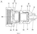
FIG. 2 is a first structural view of a first connector, a second connector, and a water pipe connector involved in the present application. -
FIG. 3 is a structural view of the first connector involved inFIG. 2 . -
FIG. 4 is a second structural view of a first connector, a second connector, and a water pipe connector involved in the present application. -
FIG. 5 is a structural view of the first connector involved inFIG. 4 . -
FIG. 6 is a structural view of a second connector involved in the present application. -
FIG. 7 is a structural view of a static water pipe connector involved in the present application. -
FIG. 8 is a structural view of a dynamic water pipe connector involved in the present application. -
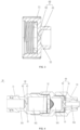
FIG. 9 is an exploded view of a relief valve involved in the present application. -
FIG. 10 is a sectional view of a relief valve involved in the present application. - Before any examples of this application are explained in detail, it is to be understood that this application is not limited to its application to the structural details and the arrangement of components set forth in the following description or illustrated in the above drawings.
- In this application, the terms "comprising", "including", "having" or any other variation thereof are intended to cover an inclusive inclusion such that a process, method, article or device comprising a series of elements includes not only those series of elements, but also other elements not expressly listed, or elements inherent in the process, method, article, or device. Without further limitations, an element defined by the phrase "comprising a ..." does not preclude the presence of additional identical elements in the process, method, article, or device comprising that element.
- In this application, the term "and/or" is a kind of association relationship describing the relationship between associated objects, which means that there can be three kinds of relationships. For example, A and/or B can indicate that A exists alone, A and B exist simultaneously, and B exists alone. In addition, the character "/" in this application generally indicates that the contextual associated objects belong to an "and/or" relationship.
- In this application, the terms "connection", "combination", "coupling" and "installation" may be direct connection, combination, coupling or installation, and may also be indirect connection, combination, coupling or installation. Among them, for example, direct connection means that two members or assemblies are connected together without intermediaries, and indirect connection means that two members or assemblies are respectively connected with at least one intermediate members and the two members or assemblies are connected by the at least one intermediate members. In addition, "connection" and "coupling" are not limited to physical or mechanical connections or couplings, and may include electrical connections or couplings.
- In this application, it is to be understood by those skilled in the art that a relative term (such as "about", "approximately", and "substantially") used in conjunction with quantity or condition includes a stated value and has a meaning dictated by the context. For example, the relative term includes at least a degree of error associated with the measurement of a particular value, a tolerance caused by manufacturing, assembly, and use associated with the particular value, and the like. Such relative term should also be considered as disclosing the range defined by the absolute values of the two endpoints. The relative term may refer to plus or minus of a certain percentage (such as 1%, 5%, 10%, or more) of an indicated value. A value that did not use the relative term should also be disclosed as a particular value with a tolerance. In addition, "substantially" when expressing a relative angular position relationship (for example, substantially parallel, substantially perpendicular), may refer to adding or subtracting a certain degree (such as 1 degree, 5 degrees, 10 degrees or more) to the indicated angle.
- In this application, those skilled in the art will understand that a function performed by an assembly may be performed by one assembly, multiple assemblies, one member, or multiple members. Likewise, a function performed by a member may be performed by one member, an assembly, or a combination of members.
- In this application, the terms "up", "down", "left", "right", "front", and "rear" " and other directional words are described based on the orientation or positional relationship shown in the drawings, and should not be understood as limitations to the examples of this application. In addition, in this context, it also needs to be understood that when it is mentioned that an element is connected "above" or "under" another element, it can not only be directly connected "above" or "under" the other element, but can also be indirectly connected "above" or "under" the other element through an intermediate element. It should also be understood that orientation words such as upper side, lower side, left side, right side, front side, and rear side do not only represent perfect orientations, but can also be understood as lateral orientations. For example, lower side may include directly below, bottom left, bottom right, front bottom, and rear bottom.
- In this application, the terms "controller", "processor", "central processor", "CPU" and "MCU" are interchangeable. Where a unit "controller", "processor", "central processing", "CPU", or "MCU" is used to perform a specific function, the specific function may be implemented by a single aforementioned unit or a plurality of the aforementioned unit.
- In this application, the term "device", "module" or "unit" may be implemented in the form of hardware or software to achieve specific functions.
- In this application, the terms "computing", "judging", "controlling", "determining", "recognizing" and the like refer to the operations and processes of a computer system or similar electronic computing device (e.g., controller, processor, etc.).
- As shown in
FIGS. 1 to 10 , the present application provides a spray fan that implements blowing and spraying functions to blow out a wind with water mist and can cool and humidify a preset field. A water source of the spray fan includes a static water source (such as water in a bucket) and a dynamic water source (such as tap water). - Specifically, referring to
FIG. 1 , the spray fan includes arack 10, ahousing assembly 20, afan assembly 30, and aspray head assembly 40. Thehousing assembly 20 is connected to therack 10 and forms an accommodation space, and thefan assembly 30 is disposed in the accommodation space. Thefan assembly 30 includesfan blades 31 and an electric motor, where the electric motor is configured to drive thefan blades 31 to rotate about an axis of the electric motor. The electric motor is sealed by a waterproof material, so as to prevent water mist from entering the electric motor under the action of an environment or the like. Specifically, the waterproof material may be, for example, a plastic film, and the electric motor is sealed by the plastic film through a process such as hot blast. - The
spray head assembly 40 includes at least onejet 41, where thejet 41 is configured to spray water mist and mounted to therack 10, thehousing assembly 20, or thefan assembly 30. After the spray fan is started, the water mist is sprayed from thejet 41 into an ambient environment, and thefan blades 31 rotate to generate an air flow to blow the water mist sprayed from thejet 41 into the air, thereby reducing the temperature of the air in the environment. It is to be understood that thejet 41 is connected to a water pipe assembly, the water pipe assembly includes a water pump and a water outlet pipe, and the water outlet pipe connects the water pump to thejet 41. Water is drawn into the water outlet pipe under the action of the water pump and can be transported to thejet 41 in a high pressure state, so as to be sprayed in an atomized state. The water pump may be a vane pump such as a centrifugal pump, an axial-flow pump, or a mixed flow pump or may be a positive-displacement pump such as a piston pump, a diaphragm pump, or a gear pump. - The spray fan further includes a water inlet pipe, where a rear end of the water inlet pipe is connected to the water pump through a pipeline, and a head end of the water inlet pipe extends outward from the spray fan and is connected to the water source. The water inlet pipe is connected to a first external water source or a second external water source by being mounted with different connectors. The first external water source is the static water source, and the second external water source is the dynamic water source. The static water source may be understood as water accommodated in a container, such as the water in the bucket. The dynamic water source may be understood as water having a certain flowrate, such as the tap water. The dynamic water source is generally accompanied with a water distribution pipe, such as a tap water pipe. The water distribution pipe is detachably connected to the water inlet pipe. A water pipe connector is provided on the water inlet pipe, where the water pipe connector includes a dynamic
water pipe connector 82 and a staticwater pipe connector 81. Referring toFIG. 7 , when the water inlet pipe is connected to the static water source, the staticwater pipe connector 81 is mounted to the water inlet pipe. Referring toFIG. 8 , when the water inlet pipe is connected to the dynamic water source, the dynamicwater pipe connector 82 is mounted to the water inlet pipe. Both the staticwater pipe connector 81 and the dynamicwater pipe connector 82 are existing structures, and the details are not repeated here. - When the dynamic water source is connected, an
adjustment device 50 is provided at a connection between the water inlet pipe and the water distribution pipe, where theadjustment device 50 is configured to adjust a flowrate of a liquid flowing in the spray fan. Referring toFIGS. 2 to 6 , theadjustment device 50 includes afirst connector 51 disposed at a rear end of the water distribution pipe and asecond connector 52 disposed at the head end of the water inlet pipe. It is to be understood that thesecond connector 52 is connected to the dynamicwater pipe connector 82 at the head end of the water inlet pipe. Thefirst connector 51 and thesecond connector 52 are configured to be structures detachably connected to each other. Specifically, the connection may be implemented in a threaded manner or in a snap-fit or plug-in manner, which is not limited here. Referring toFIGS. 2 and3 , thefirst connector 51 may adopt an American standard male connector. Referring toFIGS. 4 and5 , thefirst connector 51 may also adopt a European standard male connector. Referring toFIG. 6 , thesecond connector 52 is a female connector mating with the male connector. - The adjustment device includes a
channel 500 for the liquid to flow through, and a flowrate and pressure of the liquid flowing through thechannel 500 decrease and then increase. The adjustment device adjusts the flowrate and the pressure of the liquid, thereby reducing an effect of pressure of the water source on the water pump and extending a service life of the water pump. In this example, theadjustment device 50 is disposed upstream of the water pump. In other examples, theadjustment device 50 may be disposed downstream of the water pump. - With continued reference to
FIGS. 2 to 6 , thechannel 500 is provided with anadjustment hole 60 whose cross-section changes such that the flowrate and the pressure of the liquid flowing through thechannel 500 decrease and then increase. The flowrate and the pressure of the liquid can be controlled by theadjustment hole 60, so as to achieve speed regulation and pressure regulation. The ratio of the length to the diameter of theadjustment hole 60 is less than or equal to 0.5. In some examples, the ratio of the length to the diameter of theadjustment hole 60 is greater than 4. In some examples, the ratio of the length to the diameter of theadjustment hole 60 is greater than 0.5 and less than or equal to 4. When the liquid originally having a relatively large flowrate passes through theadjustment hole 60, the liquid is blocked at theadjustment hole 60. Since the liquid cannot change a direction suddenly, a pressure loss occurs in a process in which the liquid shrinks at theadjustment hole 60 and then diffuses after flowing out of theadjustment hole 60, and the flowrate of the liquid decreases after the liquid flows out of theadjustment hole 60. It is to be noted that thefirst connector 51 and thesecond connector 52 are each provided with awall 53, theadjustment hole 60 is defined on thewall 53, and the wall thickness of thewall 53 is the length of theadjustment hole 60. - The
jet 41 has a cross-section, and the liquid is sprayed from thejet 41 after passing through the cross-section of thejet 41. A total area of the cross-section of the at least onejet 41 is a sum of cross-sections of alljets 41. The ratio of the area of the cross-section of theadjustment hole 60 to the total area of the cross-section of the at least onejet 41 is greater than 1 and less than or equal to 45. In some examples, the ratio of the area of the cross-section of theadjustment hole 60 to the total area of the cross-section of the at least onejet 41 is greater than 1.1 and less than or equal to 20. In some examples, the ratio of the area of the cross-section of theadjustment hole 60 to the total area of the cross-section of the at least onejet 41 is greater than 1.2 and less than or equal to 10. In this example, the diameter of theadjustment hole 60 is greater than or equal to 0.1 mm and less than or equal to 6 mm. In some examples, the diameter of theadjustment hole 60 is greater than or equal to 0.4 mm and less than or equal to 3 mm. In some examples, the diameter of theadjustment hole 60 is greater than or equal to 0.6 mm and less than or equal to 1.2 mm. - In some examples, one
adjustment hole 60 is provided. Thechannel 500 includes afirst cavity 501 and asecond cavity 502. The liquid has a first flowrate when flowing through thefirst cavity 501 and has a second flowrate when flowing through thesecond cavity 502. The first flowrate is basically the same as a flowrate of water in the tap water pipe. The ratio of the first flowrate to the second flowrate is greater than or equal to 14:1 and less than or equal to 30:1. The first flowrate is far greater than the second flowrate, and it can be seen that the dynamic water source has a greatly decreased water flowrate after passing through theadjustment hole 60. A flowrate of the liquid flowing through theadjustment hole 60 is greater than or equal to 3 L/min and less than or equal to 30 L/min. In some examples, the flowrate of the liquid flowing through theadjustment hole 60 is greater than or equal to 0.5 L/min and less than or equal to 25 L/min. In some examples, the flowrate of the liquid flowing through theadjustment hole 60 is greater than or equal to 0.6 L/min and less than or equal to 22 L/min. - In some other examples, two
adjustment holes 60 are provided, and the liquid in thechannel 500 flows through the twoadjustment holes 60 in sequence. The flowrate of the liquid flowing through thechannel 500 decreases and then increases and decreases and then increases for the second time. In addition to thefirst cavity 501 and thesecond cavity 502, thechannel 500 further includes athird cavity 503 and afourth cavity 504. The liquid has the first flowrate when flowing through thefirst cavity 501, has the second flowrate when flowing through thesecond cavity 502 and thethird cavity 503, and has a third flowrate when flowing through thefourth cavity 504. The ratio of the first flowrate to the second flowrate is greater than or equal to 14:1 and less than or equal to 30:1. The ratio of the second flowrate to the third flowrate is greater than 1:1 and less than or equal to 7:3. The dynamic water source has a significantly decreased water flowrate after passing through thefirst adjustment hole 60 and a re-decreased water flowrate after passing through thesecond adjustment hole 60. The flowrate of the liquid is decreased twice when the liquid flows through thechannel 500. The flowrate of the liquid gradually decreases, achieving a better throttling effect. Specifically, the first flowrate is greater than or equal to 20 L/min and less than or equal to 22 L/min, the second flowrate is greater than or equal to 0.9 L/min and less than or equal to 1.4 L/min, and the third flowrate is greater than or equal to 0.6 L/min and less than 0.9 L/min. - The
adjustment hole 60 includes aguide portion 62 and astraight portion 61. Theguide portion 62 is disposed at an upstream position of theadjustment hole 60. Theguide portion 62 is funnel-shaped, and thestraight portion 61 is cylindrical. The diameter of a tip of theguide portion 62 is equal to the diameter of thestraight portion 61, and the tip of theguide portion 62 is connected to thestraight portion 61. Theguide portion 62 is located at the upstream position of theadjustment hole 60. When the liquid flows through thechannel 500, the liquid flows through theguide portion 62 first and then flows through thestraight portion 61 so that the flowrate of the liquid can be gradually decreased under the guidance of theguide portion 62 until the liquid flows to thestraight portion 61, thereby improving smoothness of the liquid flowing to thestraight portion 61. Theguide portion 62 is funnel-shaped to facilitate machining and save a cost. - The preceding adjustment device is disposed so that water pressure at the output of the water pump is reduced to a value less than or equal to 1.2 Mpa. The water pressure at a water outlet of the water pump is small so that the water flow impacts on the water pump weakly, and the water pump is not easily damaged and has a long lifetime.
- Referring to
FIGS. 9 and10 , the spray fan further includes arelief valve 70 disposed upstream of the water pump, where therelief valve 70 has apiston 73, aspring 74 acts on thepiston 73, and thespring 74 is configured to keep thepiston 73 at a certain distance from a water inlet end of therelief valve 70. When backpressure at the water pump exceeds a set value, thepiston 73 of therelief valve 70 retreats against thespring 74 so that arubber plug 75 inside thepiston 73 blocks the output of the water inlet end of therelief valve 70, so as to keep the pressure at the water pump at a stable pressure value. When the pressure at the water pump decreases, thespring 74 pushes thepiston 73 forward to reset thepiston 73, and the external water source passes through therelief valve 70 and enters the water pump at the rear end. The preceding action principle is repeated so that the water pump is kept in a zero-pressure state during normal operation. - In some examples, the
relief valve 70 may be disposed between thefirst connector 51 and thesecond connector 52, and avalve body 71 at the water inlet end of therelief valve 70 is detachably connected to thefirst connector 51, where the connection may be implemented in the threaded manner or in the snap-fit or plug-in manner, which is not limited here; and avalve body 72 at a water outlet end of therelief valve 70 is detachably connected to thesecond connector 52, where the connection may also be implemented in the threaded manner or in the snap-fit or plug-in manner, which is not limited here. Of course, the position of therelief valve 70 is not limited to this so long as it is ensured that therelief valve 70 is disposed upstream of the water pump. - The basic principles, main features, and advantages of this application are shown and described above. It is to be understood by those skilled in the art that the aforementioned examples do not limit the present application in any form, and all technical solutions obtained through equivalent substitutions or equivalent transformations fall within the scope of the present application.
Claims (15)
- A spray fan, comprising:a fan assembly (30) comprising a plurality of fan blades (31);an electric motor for driving the fan blades to rotate;a spray head assembly (40) configured to spray a liquid; anda water pump configured to deliver the liquid;wherein the spray fan further comprises:
an adjustment device (50) configured to adjust a flowrate of the liquid and comprising a channel (500) for the liquid to flow through, wherein a flowrate of the liquid flowing through the channel decreases and then increases. - The spray fan according to claim 1, wherein the channel is provided with an adjustment hole (60) whose cross-section changes such that the flowrate of the liquid flowing through the channel decreases and then increases.
- The spray fan according to claim 2, wherein a diameter of the adjustment hole is greater than or equal to 0.1 mm and less than or equal to 6 mm.
- The spray fan according to claim 2, wherein the spray head assembly comprises at least one jet (41), and a ratio of an area of the cross-section of the adjustment hole to a total area of a cross-section of the at least one jet is greater than 1 and less than or equal to 45.
- The spray fan according to claim 2, wherein a flowrate of the liquid flowing through the adjustment hole is greater than or equal to 3 L/min and less than or equal to 30 L/min.
- The spray fan according to claim 2, wherein two adjustment holes are provided, and the liquid in the channel flows through the two adjustment holes in sequence.
- The spray fan according to claim 1, wherein the flowrate of the liquid flowing through the channel decreases and then increases for a second time.
- The spray fan according to claim 7, wherein the liquid flowing through the channel has a first flowrate, a second flowrate, and a third flowrate, wherein the first flowrate is greater than or equal to 20 L/min and less than or equal to 22 L/min, the second flowrate is greater than or equal to 0.9 L/min and less than or equal to 1.4 L/min, and the third flowrate is greater than or equal to 0.6 L/min and less than 0.9 L/min.
- The spray fan according to claim 7, wherein the liquid flowing through the channel has a first flowrate, a second flowrate, and a third flowrate, wherein a ratio of the first flowrate to the second flowrate is greater than or equal to 14:1 and less than or equal to 30:1, and a ratio of the second flowrate to the third flowrate is greater than 1:1 and less than or equal to 7:3.
- The spray fan according to claim 2, wherein the spray fan comprises a water inlet pipe, the adjustment device comprises a first connector (51) and a second connector (52), the first connector is connected to a water distribution pipe, the second connector is connected to the water inlet pipe, the first connector and the second connector are detachably connected, and the first connector and/or the second connector are provided with the adjustment hole.
- The spray fan according to claim 1, wherein water pressure at an output of the water pump is less than or equal to 1.2 Mpa.
- The spray fan according to claim 1, wherein the spray fan comprises a water inlet pipe with an end connected to a dynamic water source or a static water source and another end connected to the water pump, the adjustment device is disposed at an end of the water inlet pipe facing away from the water pump, and the liquid flows from the dynamic water source or the static water source to the water pump through the water inlet pipe and then is sprayed out from the spray head assembly.
- The spray fan according to claim 2, wherein a ratio of a length to a diameter of the adjustment hole is less than or equal to 0.5.
- The spray fan according to claim 2, wherein the adjustment hole comprises a straight portion (61) and a funnel-shaped guide portion (62), and the guide portion is located at an upstream position of the adjustment hole relative to the straight portion.
- The spray fan according to claim 1, further comprising a relief valve (70) disposed upstream of the water pump.
Applications Claiming Priority (1)
| Application Number | Priority Date | Filing Date | Title |
|---|---|---|---|
| CN202310429885.6A CN118816307A (en) | 2023-04-20 | 2023-04-20 | Mist fan |
Publications (2)
| Publication Number | Publication Date |
|---|---|
| EP4450821A1 true EP4450821A1 (en) | 2024-10-23 |
| EP4450821B1 EP4450821B1 (en) | 2025-11-26 |
Family
ID=90104992
Family Applications (1)
| Application Number | Title | Priority Date | Filing Date |
|---|---|---|---|
| EP24160119.4A Active EP4450821B1 (en) | 2023-04-20 | 2024-02-28 | Spray fan |
Country Status (3)
| Country | Link |
|---|---|
| US (1) | US20240353124A1 (en) |
| EP (1) | EP4450821B1 (en) |
| CN (1) | CN118816307A (en) |
Families Citing this family (3)
| Publication number | Priority date | Publication date | Assignee | Title |
|---|---|---|---|---|
| USD1111157S1 (en) * | 2024-11-22 | 2026-02-03 | Hunan Chaoyu Technology Co., Ltd. | Fan |
| USD1121805S1 (en) * | 2025-01-24 | 2026-04-07 | Zhenchao Li | Electric fan |
| KR102996789B1 (en) | 2025-08-28 | 2026-07-27 | 주식회사 이비랩스 | Large Fan System with Integrated Motor-Through Water Spray |
Citations (5)
| Publication number | Priority date | Publication date | Assignee | Title |
|---|---|---|---|---|
| US6237896B1 (en) * | 1999-10-22 | 2001-05-29 | Ricky D. Hicks | Portable fan with misting nozzles |
| FR2835750A1 (en) * | 2002-02-11 | 2003-08-15 | Herve Duplessy | PROCESS FOR REFRESHING THE AMBIENT AIR BY PERMANENT HORIZONTAL ATOMIZATION OF WATER, ASSISTED BY A CENTRIFUGAL PULSE AIR VENTILATION TO COVER A PROGRAMMABLE SECTOR ZONE ENSURED BY DRIVING A STEP MOTOR |
| KR102096783B1 (en) * | 2018-09-12 | 2020-04-03 | 윤도식 | Passive Water Injection Typed Hand-Held Portable Electric Fan |
| US20210310718A1 (en) * | 2020-04-03 | 2021-10-07 | O2Cool, Llc | Portable Misting Fan |
| US20220080437A1 (en) * | 2020-04-26 | 2022-03-17 | Nanjing Chervon Industry Co., Ltd. | Misting fan |
Family Cites Families (2)
| Publication number | Priority date | Publication date | Assignee | Title |
|---|---|---|---|---|
| US6575429B2 (en) * | 2001-10-03 | 2003-06-10 | Lloyd D. Paine | Dripless hose bib |
| JP6468623B1 (en) * | 2017-11-06 | 2019-02-13 | 雅 田篭 | Mist generator |
-
2023
- 2023-04-20 CN CN202310429885.6A patent/CN118816307A/en active Pending
-
2024
- 2024-02-28 EP EP24160119.4A patent/EP4450821B1/en active Active
- 2024-03-04 US US18/594,213 patent/US20240353124A1/en active Pending
Patent Citations (5)
| Publication number | Priority date | Publication date | Assignee | Title |
|---|---|---|---|---|
| US6237896B1 (en) * | 1999-10-22 | 2001-05-29 | Ricky D. Hicks | Portable fan with misting nozzles |
| FR2835750A1 (en) * | 2002-02-11 | 2003-08-15 | Herve Duplessy | PROCESS FOR REFRESHING THE AMBIENT AIR BY PERMANENT HORIZONTAL ATOMIZATION OF WATER, ASSISTED BY A CENTRIFUGAL PULSE AIR VENTILATION TO COVER A PROGRAMMABLE SECTOR ZONE ENSURED BY DRIVING A STEP MOTOR |
| KR102096783B1 (en) * | 2018-09-12 | 2020-04-03 | 윤도식 | Passive Water Injection Typed Hand-Held Portable Electric Fan |
| US20210310718A1 (en) * | 2020-04-03 | 2021-10-07 | O2Cool, Llc | Portable Misting Fan |
| US20220080437A1 (en) * | 2020-04-26 | 2022-03-17 | Nanjing Chervon Industry Co., Ltd. | Misting fan |
Also Published As
| Publication number | Publication date |
|---|---|
| CN118816307A (en) | 2024-10-22 |
| US20240353124A1 (en) | 2024-10-24 |
| EP4450821B1 (en) | 2025-11-26 |
Similar Documents
| Publication | Publication Date | Title |
|---|---|---|
| US20240353124A1 (en) | Spray fan | |
| KR101592656B1 (en) | Air supply apparatus and method for fuel cell | |
| KR102488575B1 (en) | Control system for compressor and method of controlling the compressor | |
| US10054118B2 (en) | Relief valve assembly and components thereof | |
| US20050077057A1 (en) | Fire truck booster pump | |
| CN104763497B (en) | Common rail assembly, urea injection system and its application | |
| US20190351598A1 (en) | Cooling System Of Injection Mold | |
| CN119353265B (en) | Anti-backflow high-efficiency jet pump | |
| CN219327818U (en) | Intelligent servo air compensating valve for material conveying pipeline | |
| CN216241634U (en) | Oil source system for testing performance of aircraft landing gear | |
| CN224031006U (en) | Air flow adjusting device and application equipment thereof | |
| CN211778258U (en) | Venturi vacuum pump with self-adaptive capacity | |
| CN111075725B (en) | Safety liquid injection device and liquid injection screw compressor system | |
| CN117329424B (en) | Passive micro-lubrication system based on extreme environment | |
| CN223010849U (en) | A new type of sprayer with self-unloading structure | |
| CN217977548U (en) | Check valve and range hood | |
| CN215371484U (en) | Water separator | |
| CN222670254U (en) | Micro-fog humidifying and water supplementing device of combined air conditioner | |
| CN121363556B (en) | Vapor cooling device, compression equipment and cooling method | |
| CN215588602U (en) | Internal atomization trace lubrication system | |
| CN212225640U (en) | Pneumatic motor device for explosion-proof area | |
| KR20170107850A (en) | Header pipe in using water supply pressurize booster pump system | |
| CN101639145A (en) | Air hydraulic quick joint | |
| CN223049685U (en) | High-pressure liquid injection air intake control device and high-pressure liquid injection system | |
| CN221120468U (en) | Main water pump cavitation prevention and control system |
Legal Events
| Date | Code | Title | Description |
|---|---|---|---|
| PUAI | Public reference made under article 153(3) epc to a published international application that has entered the european phase |
Free format text: ORIGINAL CODE: 0009012 |
|
| STAA | Information on the status of an ep patent application or granted ep patent |
Free format text: STATUS: THE APPLICATION HAS BEEN PUBLISHED |
|
| AK | Designated contracting states |
Kind code of ref document: A1 Designated state(s): AL AT BE BG CH CY CZ DE DK EE ES FI FR GB GR HR HU IE IS IT LI LT LU LV MC ME MK MT NL NO PL PT RO RS SE SI SK SM TR |
|
| STAA | Information on the status of an ep patent application or granted ep patent |
Free format text: STATUS: REQUEST FOR EXAMINATION WAS MADE |
|
| 17P | Request for examination filed |
Effective date: 20250310 |
|
| STAA | Information on the status of an ep patent application or granted ep patent |
Free format text: STATUS: EXAMINATION IS IN PROGRESS |
|
| 17Q | First examination report despatched |
Effective date: 20250520 |
|
| GRAP | Despatch of communication of intention to grant a patent |
Free format text: ORIGINAL CODE: EPIDOSNIGR1 |
|
| STAA | Information on the status of an ep patent application or granted ep patent |
Free format text: STATUS: GRANT OF PATENT IS INTENDED |
|
| GRAS | Grant fee paid |
Free format text: ORIGINAL CODE: EPIDOSNIGR3 |
|
| GRAA | (expected) grant |
Free format text: ORIGINAL CODE: 0009210 |
|
| STAA | Information on the status of an ep patent application or granted ep patent |
Free format text: STATUS: THE PATENT HAS BEEN GRANTED |
|
| INTG | Intention to grant announced |
Effective date: 20251015 |
|
| AK | Designated contracting states |
Kind code of ref document: B1 Designated state(s): AL AT BE BG CH CY CZ DE DK EE ES FI FR GB GR HR HU IE IS IT LI LT LU LV MC ME MK MT NL NO PL PT RO RS SE SI SK SM TR |
|
| REG | Reference to a national code |
Ref country code: CH Ref legal event code: F10 Free format text: ST27 STATUS EVENT CODE: U-0-0-F10-F00 (AS PROVIDED BY THE NATIONAL OFFICE) Effective date: 20251126 Ref country code: GB Ref legal event code: FG4D |
|
| REG | Reference to a national code |
Ref country code: IE Ref legal event code: FG4D |
|
| REG | Reference to a national code |
Ref country code: DE Ref legal event code: R096 Ref document number: 602024001362 Country of ref document: DE |
|
| REG | Reference to a national code |
Ref country code: NL Ref legal event code: MP Effective date: 20251126 |
|
| PG25 | Lapsed in a contracting state [announced via postgrant information from national office to epo] |
Ref country code: ES Free format text: LAPSE BECAUSE OF FAILURE TO SUBMIT A TRANSLATION OF THE DESCRIPTION OR TO PAY THE FEE WITHIN THE PRESCRIBED TIME-LIMIT Effective date: 20251126 |
|
| REG | Reference to a national code |
Ref country code: LT Ref legal event code: MG9D |
|
| PG25 | Lapsed in a contracting state [announced via postgrant information from national office to epo] |
Ref country code: NO Free format text: LAPSE BECAUSE OF FAILURE TO SUBMIT A TRANSLATION OF THE DESCRIPTION OR TO PAY THE FEE WITHIN THE PRESCRIBED TIME-LIMIT Effective date: 20260226 |
|
| PGFP | Annual fee paid to national office [announced via postgrant information from national office to epo] |
Ref country code: DE Payment date: 20260128 Year of fee payment: 3 |
|
| PG25 | Lapsed in a contracting state [announced via postgrant information from national office to epo] |
Ref country code: FI Free format text: LAPSE BECAUSE OF FAILURE TO SUBMIT A TRANSLATION OF THE DESCRIPTION OR TO PAY THE FEE WITHIN THE PRESCRIBED TIME-LIMIT Effective date: 20251126 Ref country code: AT Free format text: LAPSE BECAUSE OF FAILURE TO SUBMIT A TRANSLATION OF THE DESCRIPTION OR TO PAY THE FEE WITHIN THE PRESCRIBED TIME-LIMIT Effective date: 20251126 Ref country code: HR Free format text: LAPSE BECAUSE OF FAILURE TO SUBMIT A TRANSLATION OF THE DESCRIPTION OR TO PAY THE FEE WITHIN THE PRESCRIBED TIME-LIMIT Effective date: 20251126 |
|
| REG | Reference to a national code |
Ref country code: AT Ref legal event code: MK05 Ref document number: 1861296 Country of ref document: AT Kind code of ref document: T Effective date: 20251126 |
|
| PG25 | Lapsed in a contracting state [announced via postgrant information from national office to epo] |
Ref country code: NL Free format text: LAPSE BECAUSE OF FAILURE TO SUBMIT A TRANSLATION OF THE DESCRIPTION OR TO PAY THE FEE WITHIN THE PRESCRIBED TIME-LIMIT Effective date: 20251126 |
|
| PG25 | Lapsed in a contracting state [announced via postgrant information from national office to epo] |
Ref country code: RS Free format text: LAPSE BECAUSE OF FAILURE TO SUBMIT A TRANSLATION OF THE DESCRIPTION OR TO PAY THE FEE WITHIN THE PRESCRIBED TIME-LIMIT Effective date: 20260226 |
|
| PG25 | Lapsed in a contracting state [announced via postgrant information from national office to epo] |
Ref country code: IS Free format text: LAPSE BECAUSE OF FAILURE TO SUBMIT A TRANSLATION OF THE DESCRIPTION OR TO PAY THE FEE WITHIN THE PRESCRIBED TIME-LIMIT Effective date: 20260326 |
|
| PGFP | Annual fee paid to national office [announced via postgrant information from national office to epo] |
Ref country code: FR Payment date: 20260209 Year of fee payment: 3 |
|
| PG25 | Lapsed in a contracting state [announced via postgrant information from national office to epo] |
Ref country code: PT Free format text: LAPSE BECAUSE OF FAILURE TO SUBMIT A TRANSLATION OF THE DESCRIPTION OR TO PAY THE FEE WITHIN THE PRESCRIBED TIME-LIMIT Effective date: 20260326 |
|
| PG25 | Lapsed in a contracting state [announced via postgrant information from national office to epo] |
Ref country code: PL Free format text: LAPSE BECAUSE OF FAILURE TO SUBMIT A TRANSLATION OF THE DESCRIPTION OR TO PAY THE FEE WITHIN THE PRESCRIBED TIME-LIMIT Effective date: 20251126 |
|
| PG25 | Lapsed in a contracting state [announced via postgrant information from national office to epo] |
Ref country code: LV Free format text: LAPSE BECAUSE OF FAILURE TO SUBMIT A TRANSLATION OF THE DESCRIPTION OR TO PAY THE FEE WITHIN THE PRESCRIBED TIME-LIMIT Effective date: 20251126 |
|
| PG25 | Lapsed in a contracting state [announced via postgrant information from national office to epo] |
Ref country code: BG Free format text: LAPSE BECAUSE OF FAILURE TO SUBMIT A TRANSLATION OF THE DESCRIPTION OR TO PAY THE FEE WITHIN THE PRESCRIBED TIME-LIMIT Effective date: 20251126 |
|
| PG25 | Lapsed in a contracting state [announced via postgrant information from national office to epo] |
Ref country code: LT Free format text: LAPSE BECAUSE OF FAILURE TO SUBMIT A TRANSLATION OF THE DESCRIPTION OR TO PAY THE FEE WITHIN THE PRESCRIBED TIME-LIMIT Effective date: 20251126 |
|
| PG25 | Lapsed in a contracting state [announced via postgrant information from national office to epo] |
Ref country code: SM Free format text: LAPSE BECAUSE OF FAILURE TO SUBMIT A TRANSLATION OF THE DESCRIPTION OR TO PAY THE FEE WITHIN THE PRESCRIBED TIME-LIMIT Effective date: 20251126 |
|
| PG25 | Lapsed in a contracting state [announced via postgrant information from national office to epo] |
Ref country code: DK Free format text: LAPSE BECAUSE OF FAILURE TO SUBMIT A TRANSLATION OF THE DESCRIPTION OR TO PAY THE FEE WITHIN THE PRESCRIBED TIME-LIMIT Effective date: 20251126 |
|
| PG25 | Lapsed in a contracting state [announced via postgrant information from national office to epo] |
Ref country code: IT Free format text: LAPSE BECAUSE OF FAILURE TO SUBMIT A TRANSLATION OF THE DESCRIPTION OR TO PAY THE FEE WITHIN THE PRESCRIBED TIME-LIMIT Effective date: 20251126 |
|
| PG25 | Lapsed in a contracting state [announced via postgrant information from national office to epo] |
Ref country code: EE Free format text: LAPSE BECAUSE OF FAILURE TO SUBMIT A TRANSLATION OF THE DESCRIPTION OR TO PAY THE FEE WITHIN THE PRESCRIBED TIME-LIMIT Effective date: 20251126 |
|
| PG25 | Lapsed in a contracting state [announced via postgrant information from national office to epo] |
Ref country code: CZ Free format text: LAPSE BECAUSE OF FAILURE TO SUBMIT A TRANSLATION OF THE DESCRIPTION OR TO PAY THE FEE WITHIN THE PRESCRIBED TIME-LIMIT Effective date: 20251126 |
|
| PG25 | Lapsed in a contracting state [announced via postgrant information from national office to epo] |
Ref country code: SK Free format text: LAPSE BECAUSE OF FAILURE TO SUBMIT A TRANSLATION OF THE DESCRIPTION OR TO PAY THE FEE WITHIN THE PRESCRIBED TIME-LIMIT Effective date: 20251126 |
|
| PG25 | Lapsed in a contracting state [announced via postgrant information from national office to epo] |
Ref country code: SE Free format text: LAPSE BECAUSE OF FAILURE TO SUBMIT A TRANSLATION OF THE DESCRIPTION OR TO PAY THE FEE WITHIN THE PRESCRIBED TIME-LIMIT Effective date: 20251126 |