EP4450788A1 - Ducted firewall with upper bifi bleed for modulated core ventilation - Google Patents
Ducted firewall with upper bifi bleed for modulated core ventilation Download PDFInfo
- Publication number
- EP4450788A1 EP4450788A1 EP24171443.5A EP24171443A EP4450788A1 EP 4450788 A1 EP4450788 A1 EP 4450788A1 EP 24171443 A EP24171443 A EP 24171443A EP 4450788 A1 EP4450788 A1 EP 4450788A1
- Authority
- EP
- European Patent Office
- Prior art keywords
- fan
- bypass air
- flow
- annular region
- fan bypass
- Prior art date
- Legal status (The legal status is an assumption and is not a legal conclusion. Google has not performed a legal analysis and makes no representation as to the accuracy of the status listed.)
- Pending
Links
Images



Classifications
-
- F—MECHANICAL ENGINEERING; LIGHTING; HEATING; WEAPONS; BLASTING
- F02—COMBUSTION ENGINES; HOT-GAS OR COMBUSTION-PRODUCT ENGINE PLANTS
- F02C—GAS-TURBINE PLANTS; AIR INTAKES FOR JET-PROPULSION PLANTS; CONTROLLING FUEL SUPPLY IN AIR-BREATHING JET-PROPULSION PLANTS
- F02C6/00—Plural gas-turbine plants; Combinations of gas-turbine plants with other apparatus; Adaptations of gas-turbine plants for special use
- F02C6/04—Gas-turbine plants providing heated or pressurised working fluid for other apparatus, e.g. without mechanical power output
- F02C6/06—Gas-turbine plants providing heated or pressurised working fluid for other apparatus, e.g. without mechanical power output providing compressed gas
- F02C6/08—Gas-turbine plants providing heated or pressurised working fluid for other apparatus, e.g. without mechanical power output providing compressed gas the gas being bled from the gas-turbine compressor
-
- F—MECHANICAL ENGINEERING; LIGHTING; HEATING; WEAPONS; BLASTING
- F02—COMBUSTION ENGINES; HOT-GAS OR COMBUSTION-PRODUCT ENGINE PLANTS
- F02K—JET-PROPULSION PLANTS
- F02K3/00—Plants including a gas turbine driving a compressor or a ducted fan
- F02K3/02—Plants including a gas turbine driving a compressor or a ducted fan in which part of the working fluid by-passes the turbine and combustion chamber
- F02K3/04—Plants including a gas turbine driving a compressor or a ducted fan in which part of the working fluid by-passes the turbine and combustion chamber the plant including ducted fans, i.e. fans with high volume, low pressure outputs, for augmenting the jet thrust, e.g. of double-flow type
-
- F—MECHANICAL ENGINEERING; LIGHTING; HEATING; WEAPONS; BLASTING
- F01—MACHINES OR ENGINES IN GENERAL; ENGINE PLANTS IN GENERAL; STEAM ENGINES
- F01D—NON-POSITIVE DISPLACEMENT MACHINES OR ENGINES, e.g. STEAM TURBINES
- F01D17/00—Regulating or controlling by varying flow
- F01D17/10—Final actuators
- F01D17/12—Final actuators arranged in stator parts
- F01D17/14—Final actuators arranged in stator parts varying effective cross-sectional area of nozzles or guide conduits
- F01D17/148—Final actuators arranged in stator parts varying effective cross-sectional area of nozzles or guide conduits by means of rotatable members, e.g. butterfly valves
-
- F—MECHANICAL ENGINEERING; LIGHTING; HEATING; WEAPONS; BLASTING
- F01—MACHINES OR ENGINES IN GENERAL; ENGINE PLANTS IN GENERAL; STEAM ENGINES
- F01D—NON-POSITIVE DISPLACEMENT MACHINES OR ENGINES, e.g. STEAM TURBINES
- F01D25/00—Component parts, details, or accessories, not provided for in, or of interest apart from, other groups
- F01D25/08—Cooling; Heating; Heat-insulation
- F01D25/14—Casings modified therefor
-
- F—MECHANICAL ENGINEERING; LIGHTING; HEATING; WEAPONS; BLASTING
- F01—MACHINES OR ENGINES IN GENERAL; ENGINE PLANTS IN GENERAL; STEAM ENGINES
- F01D—NON-POSITIVE DISPLACEMENT MACHINES OR ENGINES, e.g. STEAM TURBINES
- F01D9/00—Stators
- F01D9/06—Fluid supply conduits to nozzles or the like
- F01D9/065—Fluid supply or removal conduits traversing the working fluid flow, e.g. for lubrication-, cooling-, or sealing fluids
-
- F—MECHANICAL ENGINEERING; LIGHTING; HEATING; WEAPONS; BLASTING
- F02—COMBUSTION ENGINES; HOT-GAS OR COMBUSTION-PRODUCT ENGINE PLANTS
- F02C—GAS-TURBINE PLANTS; AIR INTAKES FOR JET-PROPULSION PLANTS; CONTROLLING FUEL SUPPLY IN AIR-BREATHING JET-PROPULSION PLANTS
- F02C6/00—Plural gas-turbine plants; Combinations of gas-turbine plants with other apparatus; Adaptations of gas-turbine plants for special use
- F02C6/04—Gas-turbine plants providing heated or pressurised working fluid for other apparatus, e.g. without mechanical power output
- F02C6/06—Gas-turbine plants providing heated or pressurised working fluid for other apparatus, e.g. without mechanical power output providing compressed gas
-
- F—MECHANICAL ENGINEERING; LIGHTING; HEATING; WEAPONS; BLASTING
- F02—COMBUSTION ENGINES; HOT-GAS OR COMBUSTION-PRODUCT ENGINE PLANTS
- F02C—GAS-TURBINE PLANTS; AIR INTAKES FOR JET-PROPULSION PLANTS; CONTROLLING FUEL SUPPLY IN AIR-BREATHING JET-PROPULSION PLANTS
- F02C7/00—Features, components parts, details or accessories, not provided for in, or of interest apart form groups F02C1/00 - F02C6/00; Air intakes for jet-propulsion plants
- F02C7/12—Cooling of plants
- F02C7/16—Cooling of plants characterised by cooling medium
- F02C7/18—Cooling of plants characterised by cooling medium the medium being gaseous, e.g. air
-
- F—MECHANICAL ENGINEERING; LIGHTING; HEATING; WEAPONS; BLASTING
- F02—COMBUSTION ENGINES; HOT-GAS OR COMBUSTION-PRODUCT ENGINE PLANTS
- F02C—GAS-TURBINE PLANTS; AIR INTAKES FOR JET-PROPULSION PLANTS; CONTROLLING FUEL SUPPLY IN AIR-BREATHING JET-PROPULSION PLANTS
- F02C7/00—Features, components parts, details or accessories, not provided for in, or of interest apart form groups F02C1/00 - F02C6/00; Air intakes for jet-propulsion plants
- F02C7/24—Heat or noise insulation
- F02C7/25—Fire protection or prevention
-
- F—MECHANICAL ENGINEERING; LIGHTING; HEATING; WEAPONS; BLASTING
- F04—POSITIVE - DISPLACEMENT MACHINES FOR LIQUIDS; PUMPS FOR LIQUIDS OR ELASTIC FLUIDS
- F04D—NON-POSITIVE-DISPLACEMENT PUMPS
- F04D27/00—Control, e.g. regulation, of pumps, pumping installations or pumping systems specially adapted for elastic fluids
- F04D27/009—Control, e.g. regulation, of pumps, pumping installations or pumping systems specially adapted for elastic fluids by bleeding, by passing or recycling fluid
-
- B—PERFORMING OPERATIONS; TRANSPORTING
- B64—AIRCRAFT; AVIATION; COSMONAUTICS
- B64D—EQUIPMENT FOR FITTING IN OR TO AIRCRAFT; FLIGHT SUITS; PARACHUTES; ARRANGEMENT OR MOUNTING OF POWER PLANTS OR PROPULSION TRANSMISSIONS IN AIRCRAFT
- B64D45/00—Aircraft indicators or protectors not otherwise provided for
- B64D2045/009—Fire detection or protection; Erosion protection, e.g. from airborne particles
-
- F—MECHANICAL ENGINEERING; LIGHTING; HEATING; WEAPONS; BLASTING
- F05—INDEXING SCHEMES RELATING TO ENGINES OR PUMPS IN VARIOUS SUBCLASSES OF CLASSES F01-F04
- F05D—INDEXING SCHEME FOR ASPECTS RELATING TO NON-POSITIVE-DISPLACEMENT MACHINES OR ENGINES, GAS-TURBINES OR JET-PROPULSION PLANTS
- F05D2240/00—Components
- F05D2240/10—Stators
- F05D2240/12—Fluid guiding means, e.g. vanes
- F05D2240/121—Fluid guiding means, e.g. vanes related to the leading edge of a stator vane
-
- F—MECHANICAL ENGINEERING; LIGHTING; HEATING; WEAPONS; BLASTING
- F05—INDEXING SCHEMES RELATING TO ENGINES OR PUMPS IN VARIOUS SUBCLASSES OF CLASSES F01-F04
- F05D—INDEXING SCHEME FOR ASPECTS RELATING TO NON-POSITIVE-DISPLACEMENT MACHINES OR ENGINES, GAS-TURBINES OR JET-PROPULSION PLANTS
- F05D2260/00—Function
- F05D2260/60—Fluid transfer
- F05D2260/608—Aeration, ventilation, dehumidification or moisture removal of closed spaces
Definitions
- This invention relates to gas turbine engines in general, and to gas turbine engines with cooling for components disposed external to the core gas path of the engine in particular.
- a gas turbine engine may be configured to produce thrust within a core gas path and by fan bypass air.
- Air drawn into a turbofan engine exits the fan section of the engine and either passes into the "core" of the engine (e.g., through the compressor, combustor, and turbine sections) or passes through a fan duct disposed radially outside of the core engine.
- all of the air passing through the fan duct would be dedicated to producing thrust.
- Fan air bled off of the fan duct may provide a valuable function (e.g., cooling, purging, or the like) but once bled, it very often does not provide thrust. Hence, air bled off of the fan duct very often undesirably decreases the thrust-specific fuel consumption (TSFC) of the engine.
- TSFC thrust-specific fuel consumption
- a fan bypass air duct is typically defined by an outer flow path boundary and an inner flow path boundary.
- the outer fan flow path boundary may be formed by one or more inner radial panels of the nacelle in which the engine is disposed.
- the inner fan flow path boundary may be formed by one or more panels typically referred to as inner frame structure panels ("IFS" panels).
- IFS panels collectively form an annular structure that is disposed radially outside of the outer case of the engine.
- the IFS panels and the engine outer case collectively define an annular region disposed outside of the core of the engine (referred to hereinafter as the "outside core annual region").
- a gas turbine engine will include components (e.g., fluid lines, actuators, sensors, harnesses, and the like - referred to hereinafter as "external components") that are disposed in the outside core annular region.
- components e.g., fluid lines, actuators, sensors, harnesses, and the like - referred to hereinafter as "external components"
- significant thermal energy is developed within the core of the engine; e.g., within the compressor section, the combustor section, the turbine section, or any combination thereof.
- the thermal energy developed is particularly significant during certain operational phases; e.g., maximum power at take-off, and the like.
- Some amount of the thermal energy developed within the core of the engine is transferred to the outside core annular region.
- an external component will have a maximum operating temperature, or the useful life of the external component will vary as a function of the ambient temperature (e.g., operating in a higher temperature environment may decrease the useful life of the external component).
- What is needed is a system capable of providing an air temperature environment within the outside core annular region that is acceptable to external components, one that typically does not negatively affect the useful life of external components, one that avoids the need to use expensive high operating temperature capable external components, and one that is favorable with respect to the TSFC of the engine.
- a gas turbine engine includes a fan section, a compressor section, a combustor section, a turbine section, an outer casing, an outside core annular region, and a fan air circulation system.
- the outer casing is disposed radially outside of the compressor section, combustor section, and the turbine section.
- the engine has a core gas path and a fan bypass air duct.
- the core gas path extends through the compressor, combustor, and turbine sections, and is disposed radially inside of the outer casing.
- the fan bypass air duct is defined by inner and outer radial flow path boundaries.
- the outside core annular region is disposed radially between the outer casing and the inner radial boundary flow path boundary.
- the fan air circulation system is configured to receive a flow of fan bypass air from the fan bypass air duct and selectively pass the received flow of fan bypass air into the outside core annular region.
- the fan air circulation system may include a valve that is disposable in a closed and open configurations.
- the flow of fan bypass air into the outside core annular region is volumetrically greater than the flow of fan bypass air into the outside core annular region in the closed configuration.
- the valve may be controlled to move from the closed configuration to the open configuration, and vice versa.
- the valve may be controlled to move to a plurality of open configurations.
- the plurality of open configurations may include a fully open configuration and one or more partially open configurations.
- the flow of fan bypass air into the outside core annular region in a partially open configuration is volumetrically less than the flow of fan bypass air into the outside core annular region in the fully open configuration.
- the fan air circulation system may include a manifold and a plurality of exit ports.
- the manifold and exit ports may be configured to pass the received flow of fan bypass air into the manifold and thereafter into the outside core annular region through the exit ports.
- the exit ports may be spaced apart from one another circumferentially.
- the manifold may extend circumferentially and the exit ports may be spaced equidistant from one another around a circumference of the manifold.
- the manifold may extend circumferentially and the exit ports may be non-uniformly spaced from one another around a circumference of the manifold.
- each of the exit ports may have the same fluid flow characteristics.
- the plurality of exit ports may include a first exit port having a first fluid flow characteristic and a second exit port having a second fluid flow characteristic, and the first fluid flow characteristic is different from the second fluid flow characteristic.
- the fan air circulation system may include a structure that extends into the fan bypass air duct, the structure including an air inlet.
- the air inlet is configured to receive the flow of fan bypass air from the fan bypass air duct.
- the engine may include an aft fan annular compartment defined in part by the outer casing and a firewall
- the fan air circulation system may include a manifold with a plurality of exit ports, the manifold disposed within the aft fan annular compartment.
- the fan air circulation system may be configured to have an air path that extends from the air inlet, through the structure, into the manifold, and through the exit ports.
- the firewall may separate the aft fan annular compartment from the outside core annular region, and the plurality of exit ports may extend through the firewall.
- a method of cooling one or more external components of a gas turbine engine includes fan, compressor, combustor, and turbine sections, and an outer casing disposed radially outside of the compressor, combustor, and turbine sections.
- the gas turbine engine has a core gas path that extends through the compressor, combustor, and turbine sections.
- the core gas path is disposed radially inside of the outer casing.
- a fan bypass air duct is defined by inner and outer radial flow path boundaries.
- An outside core annular region is disposed radially between the outer casing and the inner radial boundary flow path boundary.
- the one or more external components are disposed in the outside core annular region.
- the method includes: using a valve to selectively control passage of a flow of fan bypass air from the fan bypass air duct to the outside core annular region, wherein the valve is controllable to move from a first configuration to a second configuration, and controllable to move from the second configuration to the first configuration, wherein in the second configuration, the flow of fan bypass air into the outside core annular region is volumetrically greater than the flow of fan bypass air into the outside core annular region in the first configuration.
- the valve may be controllable to move to a plurality of open configurations, including a fully open configuration and one or more partially open configurations.
- the flow of fan bypass air into the outside core annular region in a partially open configuration is volumetrically less than the flow of fan bypass air into the outside core annular region in the fully open configuration.
- the method further including circumferentially distributing the flow of fan bypass air in the outside core annular region.
- a gas turbine engine includes a fan section, a compressor section, a combustor section, a turbine section, an outer casing, an outside core annular region, a fan air circulation system, and a system controller.
- the outer casing is disposed radially outside of the compressor, combustor, and turbine sections.
- the engine has a core gas path that extends through the compressor, combustor, and turbine sections.
- the core gas path is disposed radially inside of the outer casing.
- a fan bypass air duct is defined by an inner radial flow path boundary and an outer radial flow path boundary.
- the outside core annular region is disposed radially between the outer casing and the inner radial boundary flow path boundary.
- the fan air circulation system is configured to receive a flow of fan bypass air from the fan bypass air duct and to selectively pass the flow of fan bypass air into the outside core annular region using a valve.
- the system controller is in communication with the fan air circulation valve and a non-transitory memory storing instructions. The instructions when executed cause the system controller to selectively control passage of the flow of fan bypass air into the outside core annular region using the valve, the selective control including passing a first flow of fan bypass air into the outside core annular region during a first engine operating condition, and passing a second said flow of fan bypass air into the outside core annular region during a second engine operating condition, wherein the first flow of fan bypass air is volumetrically greater than the second flow of fan bypass air.
- the first engine operating condition may be a take-off condition and the second engine operating condition may be a cruise condition.
- the selective control passage of the flow of fan bypass air into the outside core annular region may be based on a thermal environment within the outside core annular region.
- aspects and/or embodiments of the present invention may include any one or more of the individual features or elements disclosed above and/or below alone or in any combination thereof.
- FIG. 1 shows a partially sectioned diagrammatic view of a geared gas turbine engine 20.
- the gas turbine engine 20 extends along an axial centerline 22 between an upstream airflow inlet 24 and a downstream airflow exhaust 26.
- the gas turbine engine 20 includes a fan section 28, a compressor section 30, a combustor section 32, and a turbine section 34.
- the combustor section 32 includes a combustor 35.
- the compressor section includes a low-pressure compressor (LPC) 36 and a high-pressure compressor (HPC) 38.
- the turbine section 34 includes a high-pressure turbine (HPT) 40 and a low-pressure turbine (LPT) 42.
- LPC low-pressure compressor
- HPC high-pressure compressor
- LPT high-pressure turbine
- LPT low-pressure turbine
- the engine may be described as having an outer casing 43 disposed radially outside of the compressor, combustor, and turbine sections 30, 32, 34 that defines an outer radial boundary of the core gas path through the engine.
- the configuration of the outer casing 43 may vary along the core gas path (e.g., a first set of components forming the outer casing 43 within the compressor section, a different set of components forming the outer casing 43 within the combustor section, and so on.
- the engine sections are arranged sequentially along the centerline 22 within an engine housing.
- the fan section 28 is connected to a geared architecture 44, for example, through a fan shaft 46.
- the geared architecture 44 and the LPC 36 are connected to and driven by the LPT 42 through a low-speed shaft 48.
- the HPC 38 is connected to and driven by the HPT 40 through a high-speed shaft 50.
- the terms “forward”, “leading”, “aft, “trailing” are used herein to indicate the relative position of a component or surface. As core gas air passes through the engine 20, a “leading edge” of a stator vane or rotor blade encounters core gas air before the “trailing edge” of the same.
- the fan section 28 is “forward” of the compressor section 30 and the turbine section 34 is “aft” of the compressor section 30.
- inner radial and “outer radial” refer to relative radial positions from the engine centerline 22.
- An inner radial component or path is disposed radially closer to the engine centerline 22 than an outer radial component or path.
- the gas turbine engine 20 diagrammatically shown is an example provided to facilitate the description herein.
- the present invention is not limited to any particular gas turbine engine configuration, including the two-spool engine configuration shown, and may be utilized with single spool gas turbine engines as well as three spool gas turbine engines and the like.
- FIG. 2 diagrammatically illustrates a gas turbine engine 20 embodiment generally like that shown in FIG. 1 , modified with a fan air circulation system 52 according to an aspect of the present invention.
- FIG. 2 diagrammatically illustrates a nacelle structure 54 and a pylon structure 56.
- the nacelle 54 includes one or more inner radial panels 58 that define the outer radial flow path boundary 60 of a fan bypass air duct 62.
- one or more panels typically referred to as inner frame structure panels (“IFS" panels 64) may be used to define the inner radial flow path boundary 66 of the fan bypass air duct 62.
- IFS inner frame structure panels
- the engine embodiment shown in FIG. 2 includes an annular region (i.e., the "outside core annular region 68") disposed between engine outer casing 43 and the inner radial flow path boundary 66 for the fan bypass air.
- annular region i.e., the "outside core annular region 68"
- the engine embodiment shown in FIG. 2 includes an aft fan annular compartment (“AF annular compartment 70") that is defined generally by a portion of the outer casing 43 (disposed radially outside of a compressor section), an annular aft inner diameter panel (“aft ID panel 72"), and a firewall 74.
- the aft ID panel 72 is disposed radially outside of and spaced apart from the outer casing 43.
- the aft ID panel 72 extends axially from the fan rotor stage and forms a part of the inner radial flow boundary for the fan bypass air duct 62.
- the firewall 74 is engaged with the outer casing 43 and the aft ID panel 72, extending therebetween in a generally radial plane.
- the AF annular compartment 70 is disposed forward of the outside core annular region 68.
- the fan air circulation system 52 includes a structure 76 that extends into the fan bypass air duct 62, a valve 78, a distribution manifold 80, and a plurality of exit ports 82 (components 78, 80, and 82 illustrated in at least FIG. 4 ).
- the fan air circulation system 52 may include a system controller 84.
- the structure 76 extending into the fan bypass air duct 62 is configured to function as an upper bifurcation member and as a fluid flow device (to facilitate the description herein, the structure will be referred to hereinafter as the "upper bifi 76").
- the upper bifi 76 may have a relatively narrow circumferential width, and a radial height that extends from the aft ID panel 72 to the outer radial flow boundary 60 of the fan bypass air duct 62.
- the upper bifi 76 includes a first air inlet 86 disposed proximate the aft ID panel 72.
- the first air inlet 86 may function as a "ram" air inlet.
- the upper bifi 76 may also include a second air inlet 88 disposed proximate the outer radial end of the upper bifi 76.
- the second air inlet 88 may be configured to capture fan bypass air flow for use as cabin air within the aircraft and the like.
- the upper bifi 76 is configured to direct fan bypass air flow around components disposed within the nacelle ("interior nacelle components") and thereby mitigate flow losses that would otherwise result from the interaction between the fan bypass air flow and the interior nacelle components.
- the upper bifi 76 is configured to provide air flow communication between the first air inlet 86 and the distribution manifold 80.
- the distribution manifold 80 may be attached to the firewall 74 and disposed within the AF annular compartment 70.
- the air flow communication between the upper bifi 76 and the distribution manifold 80 may be accomplished in a variety of different ways.
- the upper bifi 76 embodiment shown in FIGS. 2-4 includes a "C" shaped conduit having a first end disposed at the air inlet 86 and a distal second end disposed at the firewall 74.
- the distal end of the "C"-shaped conduit may be configured to extend through the firewall 74 for direct engagement with the manifold 80 (or vice versa), or there may be a piping/tubing interface that extends through the firewall 74 and engages with both the C-shaped conduit and the manifold 80.
- the present invention is not limited to any particular fluid flow interface between the C-shaped conduit and the manifold 80.
- the valve 78 is configured to permit selective adjustment of the volumetric amount of fan bypass air flow that may pass into the manifold 80.
- the valve 78 may be adjustable between an entirely closed position wherein no fan bypass air flow passes into the manifold 80 and an entirely open position wherein a maximum volumetric amount of fan bypass air flow passes into the manifold 80.
- the valve 78 may be adjustable in a plurality of partially open positions (e.g., 25% open, 50% open, 75% open, and the like) wherein less than a maximum volumetric amount of fan bypass air flow passes into the manifold 80.
- valve 78 types that may be used (e.g., ball orifice, plate orifice, and the like).
- the present invention is not limited to any particular valve type.
- the valve 78 may be actuated between operating positions (e.g., closed, partially open, fully open) by an actuator 90.
- the present invention is not limited to any particular type of actuator 90; e.g., pneumatic, electric, hydraulic.
- the actuator 90 may itself be configured to produce valve gate positional data or an independent sensor may be used to provide valve gate positional feedback.
- the manifold 80 is in fluid communication with at least one exit port 82, and preferably a plurality of exit ports 82.
- the exit ports 82 are in "fluid communication" with the manifold 80 such that fan bypass air flow may pass from the manifold 80, through the exit ports 82 and to the outside core annular region 68.
- the exit ports 82 may be integral with the manifold 80, or they may be independent of the manifold 80.
- the exit ports 82 may extend through the firewall 74.
- FIGS. 4B and 7 arbitrarily show eight (8) exit ports 82 for illustration purposes.
- the number of exit ports 82 can be varied to produce a desirable distribution of fan bypass air into the outside core annular region 68; e.g., a greater number of exit ports 82 may facilitate a more uniform circumferential distribution of fan bypass air into the outside core annular region 68.
- a gas turbine engine 20 will typically include components (e.g., fluid lines, actuators, sensors, harnesses, and the like - referred to hereinafter as "external components") that are disposed in the outside core annular region 68.
- the heat transfer path from the engine core to the outside core annular region 68 may not be circumferentially uniform.
- the external components may not be uniformly distributed around the circumference of the engine 20.
- Some external engine components may benefit from a greater amount of cooling flow than other external components; e.g., a first external component having a greater thermal tolerance than a second external component.
- the present invention fan air circulation system 52 provides a mechanism that can be used to customize the distribution of fan bypass air flow to better meet the cooling needs of the external components.
- the eight (8) exit ports 82 are shown uniformly distributed around the circumference of the manifold 80.
- the exit ports 82 may be non-uniformly distributed; e.g., with more exit ports 82 disposed in certain circumferential regions and fewer exit ports 82 disposed in other circumferential regions.
- the flow size of the exit ports 82 may be uniform or may be varied to vary the fan bypass air flow.
- the manifold 80 is diagrammatically shown in FIGS. 4A, 4B , and 7 as a single body. The present invention is not limited to any particular manifold 80 configuration.
- the manifold 80 may include a plurality of conduits rather than a single circumferentially extending conduit to facilitate a more uniform distribution of fan bypass air flow to the respective exit ports 82.
- the above described manifold 80 and exit port 82 embodiments may be combined in any combination.
- the controller 84 is in communication with other system components, such as the valve 78, sensors, and one or more controllers associated with the aircraft; e.g., the FADEC.
- the system controller 84 may be in communication with these components to control and/or receive signals therefrom to perform the functions described herein.
- the system controller 84 may include any type of computing device, computational circuit, processor(s), CPU, computer, or the like capable of executing a series of instructions that are stored in memory.
- the instructions may include an operating system, and/or executable software modules such as program files, system data, buffers, drivers, utilities, and the like.
- the executable instructions may apply to any functionality described herein to enable the system to accomplish the same algorithmically and/or coordination of system components.
- the system controller 84 includes or is in communication with one or more memory devices. The present invention is not limited to any particular type of memory device, and the memory device may store instructions and/or data in a non-transitory manner. Examples of memory devices that may be used include read-only memory, random access memory, volatile memory, non-volatile memory, static memory, dynamic memory, flash memory, cache memory, and/or any device that stores digital information.
- the system controller 84 may include, or may be in communication with, an input device that enables a user to enter data and/or instructions, and may include, or be in communication with, an output device. Communications between the system controller 84 and other system components may be via a hardwire connection or via a wireless connection.
- air drawn into the engine 20 passes through the fan section 28 of the engine 20 and either passes into the "core" of the engine 20 (e.g., through the compressor, combustor, and turbine sections) or passes into the fan bypass air duct 62 disposed radially outside of the core engine.
- the fan bypass air duct 62 In an ideal scenario, all of the air passing through the fan bypass air duct 62 would be dedicated to producing thrust. In reality, however, it is common to bleed some amount of fan bypass air off of the fan bypass air duct 62 for a variety of different uses; e.g., for cooling purposes, for purging purposes, or the like.
- Fan bypass air bled off of the fan bypass air duct 62 may provide a valuable function (e.g., cooling, purging, or the like) but once bled, it very often does not provide thrust. Hence, air bled off of the fan bypass air duct 62 very often undesirably decreases the thrust-specific fuel consumption (TSFC) of the engine 20.
- TSFC thrust-specific fuel consumption
- the present invention system provides a fan air circulation system 52 that is configurable and/or can be controlled to provide cooling air into the outside core annular region 68 for cooling external components of the engine 20.
- the present invention system fan air circulation system 52 is controllable to selectively provide varying amounts of fan bypass air for cooling purposes.
- the present invention system fan air circulation system 52 can be controlled to deliver a maximum amount of fan bypass air for cooling purposes.
- the present invention system fan air circulation system 52 can be controlled to deliver less than a maximum amount of fan bypass air for cooling purposes; i.e., an optimum amount of cooling air.
- a desired volumetric flow of fan bypass air for cooling purposes may be based on empirical data (e.g., data collected for various operating conditions) or based on real-time sensor data, or any combination thereof, which is in turn used by the system controller 84 to control the valve 78 to produce the desired volumetric flow of fan bypass air for cooling purposes.
- the stored instructions may relate engine operating conditions to temperatures within the outside core annular region 68 as a function of engine operating conditions, engine operating conditions as a function of time, may consider maximum allowable temperatures for external components, and dictate the amount of cooling air required as a function thereof.
- the stored instructions may be based on empirical data, or real-time sensor data, or any combination thereof. If the system controller 84 utilizes empirical data, the aforesaid data may be within the system controller 84 stored instructions, or the stored instructions may be based on the empirical data.
- the system controller 84 may determine an appropriate valve configuration (to produce the desired volumetric flow of fan bypass air for cooling purposes) based on parameters such as the thrust setting of the engine, the amount of time at a particular thrust setting, the altitude of the aircraft, the ambient air temperature, predetermined maximum external component temperatures, and the like. In this manner, only the amount of air that is required for cooling is bled off of the fan bypass air duct 62. The decrease in the amount of fan bypass air bled off is understood to make an appreciable difference in the engine's TSFC.
- configurations and/or positions of the present invention manifold exit ports 82 that deliver the desired amount of cooling air at the desired circumferential position are also understood to eliminate cooling air waste (i.e., cooling air delivered where it is not needed).
- cooling air waste i.e., cooling air delivered where it is not needed.
- the amount of fan bypass air bled off is understood to be decreased and the engine's TSFC thereby increased.
- any one of these structures may describe the operations as a sequential process, many of the operations can be performed in parallel or concurrently.
- the order of the operations may be rearranged.
- a process may correspond to a method, a function, a procedure, a subroutine, a subprogram, etc.
Landscapes
- Engineering & Computer Science (AREA)
- Chemical & Material Sciences (AREA)
- Combustion & Propulsion (AREA)
- Mechanical Engineering (AREA)
- General Engineering & Computer Science (AREA)
- Life Sciences & Earth Sciences (AREA)
- Sustainable Development (AREA)
- Physics & Mathematics (AREA)
- Fluid Mechanics (AREA)
- Structures Of Non-Positive Displacement Pumps (AREA)
Abstract
A gas turbine engine (20) includes fan, compressor, combustor, and turbine sections (28, 30, 32, 34), an outer casing (43), an outside core annular region (68), and a fan air circulation system (52). The outer casing (43) is disposed radially outside of the compressor, combustor, and turbine sections (28, 30, 32, 34). A core gas path extends through the compressor, combustor, and turbine sections (28, 30, 32, 34), and is disposed radially inside of the outer casing (43). A fan bypass air duct (62) is defined by inner and outer radial flow path boundaries (66, 60). The outside core annular region (68) is disposed radially between the outer casing (43) and the inner radial flow path boundary (66). The fan air circulation system (52) is configured to receive fan bypass air from the fan bypass air duct (62) and selectively pass the received fan bypass air into the outside core annular region (68).
Description
- This invention relates to gas turbine engines in general, and to gas turbine engines with cooling for components disposed external to the core gas path of the engine in particular.
- A gas turbine engine (e.g., a turbofan engine) may be configured to produce thrust within a core gas path and by fan bypass air. Air drawn into a turbofan engine exits the fan section of the engine and either passes into the "core" of the engine (e.g., through the compressor, combustor, and turbine sections) or passes through a fan duct disposed radially outside of the core engine. In an ideal scenario, all of the air passing through the fan duct would be dedicated to producing thrust. In reality, however, it is common to bleed some amount of fan air off of the fan duct for a variety of different uses; e.g., for cooling purposes, for purging purposes, or the like. Fan air bled off of the fan duct may provide a valuable function (e.g., cooling, purging, or the like) but once bled, it very often does not provide thrust. Hence, air bled off of the fan duct very often undesirably decreases the thrust-specific fuel consumption (TSFC) of the engine.
- A fan bypass air duct is typically defined by an outer flow path boundary and an inner flow path boundary. The outer fan flow path boundary may be formed by one or more inner radial panels of the nacelle in which the engine is disposed. The inner fan flow path boundary may be formed by one or more panels typically referred to as inner frame structure panels ("IFS" panels). The IFS panels collectively form an annular structure that is disposed radially outside of the outer case of the engine. The IFS panels and the engine outer case collectively define an annular region disposed outside of the core of the engine (referred to hereinafter as the "outside core annual region"). In many instances, a gas turbine engine will include components (e.g., fluid lines, actuators, sensors, harnesses, and the like - referred to hereinafter as "external components") that are disposed in the outside core annular region. During operation of the engine, significant thermal energy is developed within the core of the engine; e.g., within the compressor section, the combustor section, the turbine section, or any combination thereof. The thermal energy developed is particularly significant during certain operational phases; e.g., maximum power at take-off, and the like. Some amount of the thermal energy developed within the core of the engine is transferred to the outside core annular region. In many instances, an external component will have a maximum operating temperature, or the useful life of the external component will vary as a function of the ambient temperature (e.g., operating in a higher temperature environment may decrease the useful life of the external component).
- What is needed is a system capable of providing an air temperature environment within the outside core annular region that is acceptable to external components, one that typically does not negatively affect the useful life of external components, one that avoids the need to use expensive high operating temperature capable external components, and one that is favorable with respect to the TSFC of the engine.
- According to an aspect of the present invention, a gas turbine engine is provided that includes a fan section, a compressor section, a combustor section, a turbine section, an outer casing, an outside core annular region, and a fan air circulation system. The outer casing is disposed radially outside of the compressor section, combustor section, and the turbine section. The engine has a core gas path and a fan bypass air duct. The core gas path extends through the compressor, combustor, and turbine sections, and is disposed radially inside of the outer casing. The fan bypass air duct is defined by inner and outer radial flow path boundaries. The outside core annular region is disposed radially between the outer casing and the inner radial boundary flow path boundary. The fan air circulation system is configured to receive a flow of fan bypass air from the fan bypass air duct and selectively pass the received flow of fan bypass air into the outside core annular region.
- Optionally, and in accordance with the above, the fan air circulation system may include a valve that is disposable in a closed and open configurations. In the open configuration, the flow of fan bypass air into the outside core annular region is volumetrically greater than the flow of fan bypass air into the outside core annular region in the closed configuration.
- Optionally, and in accordance with any of the above, the valve may be controlled to move from the closed configuration to the open configuration, and vice versa.
- Optionally, and in accordance with any of the above, the valve may be controlled to move to a plurality of open configurations.
- Optionally, and in accordance with any of the above, the plurality of open configurations may include a fully open configuration and one or more partially open configurations. The flow of fan bypass air into the outside core annular region in a partially open configuration is volumetrically less than the flow of fan bypass air into the outside core annular region in the fully open configuration.
- Optionally, and in accordance with any of the above, the fan air circulation system may include a manifold and a plurality of exit ports. The manifold and exit ports may be configured to pass the received flow of fan bypass air into the manifold and thereafter into the outside core annular region through the exit ports.
- Optionally, and in accordance with any of the above, the exit ports may be spaced apart from one another circumferentially.
- Optionally, and in accordance with any of the above, the manifold may extend circumferentially and the exit ports may be spaced equidistant from one another around a circumference of the manifold.
- Optionally, and in accordance with any of the above, the manifold may extend circumferentially and the exit ports may be non-uniformly spaced from one another around a circumference of the manifold.
- Optionally, and in accordance with any of the above, each of the exit ports may have the same fluid flow characteristics.
- Optionally, and in accordance with any of the above, the plurality of exit ports may include a first exit port having a first fluid flow characteristic and a second exit port having a second fluid flow characteristic, and the first fluid flow characteristic is different from the second fluid flow characteristic.
- Optionally, and in accordance with any of the above, the fan air circulation system may include a structure that extends into the fan bypass air duct, the structure including an air inlet. The air inlet is configured to receive the flow of fan bypass air from the fan bypass air duct.
- Optionally, and in accordance with any of the above, the engine may include an aft fan annular compartment defined in part by the outer casing and a firewall, and the fan air circulation system may include a manifold with a plurality of exit ports, the manifold disposed within the aft fan annular compartment. The fan air circulation system may be configured to have an air path that extends from the air inlet, through the structure, into the manifold, and through the exit ports.
- Optionally, and in accordance with any of the above, the firewall may separate the aft fan annular compartment from the outside core annular region, and the plurality of exit ports may extend through the firewall.
- According to an aspect of the present invention, a method of cooling one or more external components of a gas turbine engine is provided. The gas turbine engine includes fan, compressor, combustor, and turbine sections, and an outer casing disposed radially outside of the compressor, combustor, and turbine sections. The gas turbine engine has a core gas path that extends through the compressor, combustor, and turbine sections. The core gas path is disposed radially inside of the outer casing. A fan bypass air duct is defined by inner and outer radial flow path boundaries. An outside core annular region is disposed radially between the outer casing and the inner radial boundary flow path boundary. The one or more external components are disposed in the outside core annular region. The method includes: using a valve to selectively control passage of a flow of fan bypass air from the fan bypass air duct to the outside core annular region, wherein the valve is controllable to move from a first configuration to a second configuration, and controllable to move from the second configuration to the first configuration, wherein in the second configuration, the flow of fan bypass air into the outside core annular region is volumetrically greater than the flow of fan bypass air into the outside core annular region in the first configuration.
- Optionally, and in accordance with any of the above, the valve may be controllable to move to a plurality of open configurations, including a fully open configuration and one or more partially open configurations. The flow of fan bypass air into the outside core annular region in a partially open configuration is volumetrically less than the flow of fan bypass air into the outside core annular region in the fully open configuration.
- Optionally, and in accordance with any of the above, the method further including circumferentially distributing the flow of fan bypass air in the outside core annular region.
- According to another aspect of the present invention, a gas turbine engine is provided that includes a fan section, a compressor section, a combustor section, a turbine section, an outer casing, an outside core annular region, a fan air circulation system, and a system controller. The outer casing is disposed radially outside of the compressor, combustor, and turbine sections. The engine has a core gas path that extends through the compressor, combustor, and turbine sections. The core gas path is disposed radially inside of the outer casing. A fan bypass air duct is defined by an inner radial flow path boundary and an outer radial flow path boundary. The outside core annular region is disposed radially between the outer casing and the inner radial boundary flow path boundary. The fan air circulation system is configured to receive a flow of fan bypass air from the fan bypass air duct and to selectively pass the flow of fan bypass air into the outside core annular region using a valve. The system controller is in communication with the fan air circulation valve and a non-transitory memory storing instructions. The instructions when executed cause the system controller to selectively control passage of the flow of fan bypass air into the outside core annular region using the valve, the selective control including passing a first flow of fan bypass air into the outside core annular region during a first engine operating condition, and passing a second said flow of fan bypass air into the outside core annular region during a second engine operating condition, wherein the first flow of fan bypass air is volumetrically greater than the second flow of fan bypass air.
- Optionally, and in accordance with any of the above, the first engine operating condition may be a take-off condition and the second engine operating condition may be a cruise condition.
- Optionally, and in accordance with any of the above, the selective control passage of the flow of fan bypass air into the outside core annular region may be based on a thermal environment within the outside core annular region.
- The foregoing features and elements may be combined in various combinations without exclusivity, unless expressly indicated otherwise. For example, aspects and/or embodiments of the present invention may include any one or more of the individual features or elements disclosed above and/or below alone or in any combination thereof. These features and elements as well as the operation thereof will become more apparent in light of the following description and the accompanying drawings. It should be understood, however, the following description and drawings are intended to be exemplary in nature and non-limiting.
-
-
FIG. 1 is a diagrammatic sectional view of a gas turbine engine. -
FIG. 2 is a diagrammatic sectional view of a present invention gas turbine engine embodiment. -
FIG. 3 is a perspective view of a present invention gas turbine engine embodiment. -
FIG. 4 is a diagrammatic side view of a present invention fan air circulation system embodiment. -
FIG. 4A is a diagrammatic planar view of system embodiment shown inFIG. 4 , from a forward looking aft perspective. -
FIG. 4B is a diagrammatic planar view of system embodiment shown inFIG. 4 , from an aft looking forward perspective. -
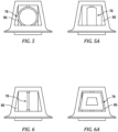
FIG. 5 is a partial view of a present invention structure including a valve embodiment shown in an open position. -
FIG. 5A is a partial view of the structure shown inFIG. 5 now in a closed position. -
FIG. 6 is a partial view of a present invention structure including a valve embodiment shown in an open position. -
FIG. 6A is a partial view of the structure shown inFIG. 6 now in a closed position. -
FIG. 7 is a diagrammatic perspective view of a present invention fan air circulation system embodiment. -
FIG. 1 shows a partially sectioned diagrammatic view of a gearedgas turbine engine 20. Thegas turbine engine 20 extends along anaxial centerline 22 between anupstream airflow inlet 24 and adownstream airflow exhaust 26. Thegas turbine engine 20 includes afan section 28, acompressor section 30, acombustor section 32, and aturbine section 34. Thecombustor section 32 includes acombustor 35. The compressor section includes a low-pressure compressor (LPC) 36 and a high-pressure compressor (HPC) 38. Theturbine section 34 includes a high-pressure turbine (HPT) 40 and a low-pressure turbine (LPT) 42. The engine may be described as having anouter casing 43 disposed radially outside of the compressor, combustor, andturbine sections outer casing 43 may vary along the core gas path (e.g., a first set of components forming theouter casing 43 within the compressor section, a different set of components forming theouter casing 43 within the combustor section, and so on. The engine sections are arranged sequentially along thecenterline 22 within an engine housing. Thefan section 28 is connected to a gearedarchitecture 44, for example, through afan shaft 46. The gearedarchitecture 44 and theLPC 36 are connected to and driven by theLPT 42 through a low-speed shaft 48. TheHPC 38 is connected to and driven by theHPT 40 through a high-speed shaft 50. The terms "forward", "leading", "aft, "trailing" are used herein to indicate the relative position of a component or surface. As core gas air passes through theengine 20, a "leading edge" of a stator vane or rotor blade encounters core gas air before the "trailing edge" of the same. In a conventional axial engine such as that shown inFIG. 1 , thefan section 28 is "forward" of thecompressor section 30 and theturbine section 34 is "aft" of thecompressor section 30. The terms "inner radial" and "outer radial" refer to relative radial positions from theengine centerline 22. An inner radial component or path is disposed radially closer to theengine centerline 22 than an outer radial component or path. Thegas turbine engine 20 diagrammatically shown is an example provided to facilitate the description herein. The present invention is not limited to any particular gas turbine engine configuration, including the two-spool engine configuration shown, and may be utilized with single spool gas turbine engines as well as three spool gas turbine engines and the like. -
FIG. 2 diagrammatically illustrates agas turbine engine 20 embodiment generally like that shown inFIG. 1 , modified with a fanair circulation system 52 according to an aspect of the present invention.FIG. 2 diagrammatically illustrates anacelle structure 54 and apylon structure 56. Thenacelle 54 includes one or more inner radial panels 58 that define the outer radial flow path boundary 60 of a fanbypass air duct 62. As will be detailed herein, one or more panels typically referred to as inner frame structure panels ("IFS" panels 64) may be used to define the inner radial flow path boundary 66 of the fanbypass air duct 62. - The engine embodiment shown in
FIG. 2 includes an annular region (i.e., the "outside coreannular region 68") disposed between engineouter casing 43 and the inner radial flow path boundary 66 for the fan bypass air. - The engine embodiment shown in
FIG. 2 includes an aft fan annular compartment ("AFannular compartment 70") that is defined generally by a portion of the outer casing 43 (disposed radially outside of a compressor section), an annular aft inner diameter panel ("aft ID panel 72"), and afirewall 74. Theaft ID panel 72 is disposed radially outside of and spaced apart from theouter casing 43. Theaft ID panel 72 extends axially from the fan rotor stage and forms a part of the inner radial flow boundary for the fanbypass air duct 62. Thefirewall 74 is engaged with theouter casing 43 and theaft ID panel 72, extending therebetween in a generally radial plane. The AFannular compartment 70 is disposed forward of the outside coreannular region 68. - The fan
air circulation system 52 includes astructure 76 that extends into the fanbypass air duct 62, avalve 78, adistribution manifold 80, and a plurality of exit ports 82 (components FIG. 4 ). In some embodiments, the fanair circulation system 52 may include asystem controller 84. - In the embodiments shown in
FIGS. 3-4B , thestructure 76 extending into the fan bypass air duct 62 (seeFIG. 2 ) is configured to function as an upper bifurcation member and as a fluid flow device (to facilitate the description herein, the structure will be referred to hereinafter as the "upper bifi 76"). Theupper bifi 76 may have a relatively narrow circumferential width, and a radial height that extends from theaft ID panel 72 to the outer radial flow boundary 60 of the fanbypass air duct 62. Theupper bifi 76 includes afirst air inlet 86 disposed proximate theaft ID panel 72. In this configuration, thefirst air inlet 86 may function as a "ram" air inlet. In some embodiments, theupper bifi 76 may also include asecond air inlet 88 disposed proximate the outer radial end of theupper bifi 76. Thesecond air inlet 88 may be configured to capture fan bypass air flow for use as cabin air within the aircraft and the like. With the exception of the first air inlet 86 (and thesecond air inlet 88 when included), theupper bifi 76 is configured to direct fan bypass air flow around components disposed within the nacelle ("interior nacelle components") and thereby mitigate flow losses that would otherwise result from the interaction between the fan bypass air flow and the interior nacelle components. - The
upper bifi 76 is configured to provide air flow communication between thefirst air inlet 86 and thedistribution manifold 80. As will be detailed hereinafter, thedistribution manifold 80 may be attached to thefirewall 74 and disposed within the AFannular compartment 70. The air flow communication between theupper bifi 76 and thedistribution manifold 80 may be accomplished in a variety of different ways. For example, theupper bifi 76 embodiment shown inFIGS. 2-4 includes a "C" shaped conduit having a first end disposed at theair inlet 86 and a distal second end disposed at thefirewall 74. The distal end of the "C"-shaped conduit may be configured to extend through thefirewall 74 for direct engagement with the manifold 80 (or vice versa), or there may be a piping/tubing interface that extends through thefirewall 74 and engages with both the C-shaped conduit and the manifold 80. The present invention is not limited to any particular fluid flow interface between the C-shaped conduit and the manifold 80. - The
valve 78 is configured to permit selective adjustment of the volumetric amount of fan bypass air flow that may pass into themanifold 80. In some embodiments, thevalve 78 may be adjustable between an entirely closed position wherein no fan bypass air flow passes into the manifold 80 and an entirely open position wherein a maximum volumetric amount of fan bypass air flow passes into themanifold 80. In some embodiments, thevalve 78 may be adjustable in a plurality of partially open positions (e.g., 25% open, 50% open, 75% open, and the like) wherein less than a maximum volumetric amount of fan bypass air flow passes into themanifold 80.FIGS. 5, 5A, 6, and 6A diagrammatically illustrate examples ofvalve 78 types that may be used (e.g., ball orifice, plate orifice, and the like). The present invention is not limited to any particular valve type. Thevalve 78 may be actuated between operating positions (e.g., closed, partially open, fully open) by anactuator 90. The present invention is not limited to any particular type ofactuator 90; e.g., pneumatic, electric, hydraulic. Theactuator 90 may itself be configured to produce valve gate positional data or an independent sensor may be used to provide valve gate positional feedback. - The manifold 80 is in fluid communication with at least one
exit port 82, and preferably a plurality ofexit ports 82. Theexit ports 82 are in "fluid communication" with the manifold 80 such that fan bypass air flow may pass from the manifold 80, through theexit ports 82 and to the outside coreannular region 68. Theexit ports 82 may be integral with the manifold 80, or they may be independent of the manifold 80. Theexit ports 82 may extend through thefirewall 74.FIGS. 4B and7 arbitrarily show eight (8)exit ports 82 for illustration purposes. The number ofexit ports 82 can be varied to produce a desirable distribution of fan bypass air into the outside coreannular region 68; e.g., a greater number ofexit ports 82 may facilitate a more uniform circumferential distribution of fan bypass air into the outside coreannular region 68. - As will be described herein, a
gas turbine engine 20 will typically include components (e.g., fluid lines, actuators, sensors, harnesses, and the like - referred to hereinafter as "external components") that are disposed in the outside coreannular region 68. The heat transfer path from the engine core to the outside coreannular region 68 may not be circumferentially uniform. The external components may not be uniformly distributed around the circumference of theengine 20. Some external engine components may benefit from a greater amount of cooling flow than other external components; e.g., a first external component having a greater thermal tolerance than a second external component. The present invention fanair circulation system 52 provides a mechanism that can be used to customize the distribution of fan bypass air flow to better meet the cooling needs of the external components. For example, in the system diagrammatically shown inFIGS. 4B and7 , the eight (8)exit ports 82 are shown uniformly distributed around the circumference of the manifold 80. In alternative embodiments, theexit ports 82 may be non-uniformly distributed; e.g., withmore exit ports 82 disposed in certain circumferential regions andfewer exit ports 82 disposed in other circumferential regions. In other embodiments, the flow size of theexit ports 82 may be uniform or may be varied to vary the fan bypass air flow. The manifold 80 is diagrammatically shown inFIGS. 4A, 4B , and7 as a single body. The present invention is not limited to anyparticular manifold 80 configuration. For example, in some embodiments, the manifold 80 may include a plurality of conduits rather than a single circumferentially extending conduit to facilitate a more uniform distribution of fan bypass air flow to therespective exit ports 82. The above describedmanifold 80 andexit port 82 embodiments may be combined in any combination. - In those present invention system embodiments that include a
system controller 84, thecontroller 84 is in communication with other system components, such as thevalve 78, sensors, and one or more controllers associated with the aircraft; e.g., the FADEC. Thesystem controller 84 may be in communication with these components to control and/or receive signals therefrom to perform the functions described herein. Thesystem controller 84 may include any type of computing device, computational circuit, processor(s), CPU, computer, or the like capable of executing a series of instructions that are stored in memory. The instructions may include an operating system, and/or executable software modules such as program files, system data, buffers, drivers, utilities, and the like. The executable instructions may apply to any functionality described herein to enable the system to accomplish the same algorithmically and/or coordination of system components. Thesystem controller 84 includes or is in communication with one or more memory devices. The present invention is not limited to any particular type of memory device, and the memory device may store instructions and/or data in a non-transitory manner. Examples of memory devices that may be used include read-only memory, random access memory, volatile memory, non-volatile memory, static memory, dynamic memory, flash memory, cache memory, and/or any device that stores digital information. Thesystem controller 84 may include, or may be in communication with, an input device that enables a user to enter data and/or instructions, and may include, or be in communication with, an output device. Communications between thesystem controller 84 and other system components may be via a hardwire connection or via a wireless connection. - In the operation of a
gas turbine engine 20 with thepresent invention system 52, air drawn into theengine 20 passes through thefan section 28 of theengine 20 and either passes into the "core" of the engine 20 (e.g., through the compressor, combustor, and turbine sections) or passes into the fanbypass air duct 62 disposed radially outside of the core engine. In an ideal scenario, all of the air passing through the fanbypass air duct 62 would be dedicated to producing thrust. In reality, however, it is common to bleed some amount of fan bypass air off of the fanbypass air duct 62 for a variety of different uses; e.g., for cooling purposes, for purging purposes, or the like. Fan bypass air bled off of the fanbypass air duct 62 may provide a valuable function (e.g., cooling, purging, or the like) but once bled, it very often does not provide thrust. Hence, air bled off of the fanbypass air duct 62 very often undesirably decreases the thrust-specific fuel consumption (TSFC) of theengine 20. - The present invention system provides a fan
air circulation system 52 that is configurable and/or can be controlled to provide cooling air into the outside coreannular region 68 for cooling external components of theengine 20. In particular, the present invention system fanair circulation system 52 is controllable to selectively provide varying amounts of fan bypass air for cooling purposes. In an engine operating condition wherein high thermal loads are produced (e.g., maximum power at take-off, or the like), the present invention system fanair circulation system 52 can be controlled to deliver a maximum amount of fan bypass air for cooling purposes. In an engine operating condition where lower thermal loads are produced (e.g., at cruise, or the like), the present invention system fanair circulation system 52 can be controlled to deliver less than a maximum amount of fan bypass air for cooling purposes; i.e., an optimum amount of cooling air. A desired volumetric flow of fan bypass air for cooling purposes may be based on empirical data (e.g., data collected for various operating conditions) or based on real-time sensor data, or any combination thereof, which is in turn used by thesystem controller 84 to control thevalve 78 to produce the desired volumetric flow of fan bypass air for cooling purposes. The stored instructions may relate engine operating conditions to temperatures within the outside coreannular region 68 as a function of engine operating conditions, engine operating conditions as a function of time, may consider maximum allowable temperatures for external components, and dictate the amount of cooling air required as a function thereof. As stated herein, the stored instructions may be based on empirical data, or real-time sensor data, or any combination thereof. If thesystem controller 84 utilizes empirical data, the aforesaid data may be within thesystem controller 84 stored instructions, or the stored instructions may be based on the empirical data. As an example, thesystem controller 84 may determine an appropriate valve configuration (to produce the desired volumetric flow of fan bypass air for cooling purposes) based on parameters such as the thrust setting of the engine, the amount of time at a particular thrust setting, the altitude of the aircraft, the ambient air temperature, predetermined maximum external component temperatures, and the like. In this manner, only the amount of air that is required for cooling is bled off of the fanbypass air duct 62. The decrease in the amount of fan bypass air bled off is understood to make an appreciable difference in the engine's TSFC. Furthermore, configurations and/or positions of the present inventionmanifold exit ports 82 that deliver the desired amount of cooling air at the desired circumferential position are also understood to eliminate cooling air waste (i.e., cooling air delivered where it is not needed). As a result, the amount of fan bypass air bled off is understood to be decreased and the engine's TSFC thereby increased. - While the principles of the invention have been described above in connection with specific apparatuses and methods, it is to be clearly understood that this description is made only by way of example and not as limitation on the scope of the invention. Specific details are given in the above description to provide a thorough understanding of the embodiments. However, it is understood that the embodiments may be practiced without these specific details.
- It is noted that the embodiments may be described as a process which is depicted as a flowchart, a flow diagram, a block diagram, etc. Although any one of these structures may describe the operations as a sequential process, many of the operations can be performed in parallel or concurrently. In addition, the order of the operations may be rearranged. A process may correspond to a method, a function, a procedure, a subroutine, a subprogram, etc.
- The singular forms "a," "an," and "the" refer to one or more than one, unless the context clearly dictates otherwise. For example, the term "comprising a specimen" includes single or plural specimens and is considered equivalent to the phrase "comprising at least one specimen." The term "or" refers to a single element of stated alternative elements or a combination of two or more elements unless the context clearly indicates otherwise. As used herein, "comprises" means "includes." Thus, "comprising A or B," means "including A or B, or A and B," without excluding additional elements.
- It is noted that various connections are set forth between elements in the present description and drawings (the contents of which are included in this invention by way of reference). It is noted that these connections are general and, unless specified otherwise, may be direct or indirect and that this specification is not intended to be limiting in this respect. Any reference to attached, fixed, connected or the like may include permanent, removable, temporary, partial, full and/or any other possible attachment option.
- No element, component, or method step in the present invention is intended to be dedicated to the public regardless of whether the element, component, or method step is explicitly recited in the claims. As used herein, the terms "comprise", "comprising", or any other variation thereof, are intended to cover a non-exclusive inclusion, such that a process, method, article, or apparatus that comprises a list of elements does not include only those elements but may include other elements not expressly listed or inherent to such process, method, article, or apparatus.
- While various inventive aspects, concepts and features of the inventions may be described and illustrated herein as embodied in combination in the exemplary embodiments, these various aspects, concepts, and features may be used in many alternative embodiments, either individually or in various combinations and sub-combinations thereof. Unless expressly excluded herein all such combinations and sub-combinations are intended to be within the scope of the present application. Still further, while various alternative embodiments as to the various aspects, concepts, and features of the inventions--such as alternative materials, structures, configurations, methods, devices, and components, and so on--may be described herein, such descriptions are not intended to be a complete or exhaustive list of available alternative embodiments, whether presently known or later developed. Those skilled in the art may readily adopt one or more of the inventive aspects, concepts, or features into additional embodiments and uses within the scope of the present application even if such embodiments are not expressly disclosed herein. For example, in the exemplary embodiments described above within the Detailed Description portion of the present specification, elements may be described as individual units and shown as independent of one another to facilitate the description. In alternative embodiments, such elements may be configured as combined elements. It is further noted that various method or process steps for embodiments of the present invention are described herein. The description may present method and/or process steps as a particular sequence. However, to the extent that the method or process does not rely on the particular order of steps set forth herein, the method or process should not be limited to the particular sequence of steps described. As one of ordinary skill in the art would appreciate, other sequences of steps may be possible. Therefore, the particular order of the steps set forth in the description should not be construed as a limitation.
Claims (15)
- A gas turbine engine (20), comprising:a fan section (28);a compressor section (30);a combustor section (32);a turbine section (34);an outer casing (43) disposed radially outside of the compressor section (30), the combustor section (32) and the turbine section (34);a core gas path that extends through the compressor section (30), the combustor section (32) and the turbine section (34), the core gas path disposed radially inside of the outer casing (43);a fan bypass air duct (62) defined by an inner radial flow path boundary (66) and an outer radial flow path boundary (60);an outside core annular region (68) radially disposed between the outer casing (43) and the inner radial flow path boundary (66); anda fan air circulation system (52) configured to receive a flow of fan bypass air from the fan bypass air duct (62) and selectively pass the received flow of fan bypass air into the outside core annular region (68).
- The gas turbine engine (20) of claim 1, wherein the fan air circulation system (52) includes a valve (78) that is disposable in a closed configuration and an open configuration, and in the open configuration, the flow of fan bypass air into the outside core annular region (68) is volumetrically greater than the flow of fan bypass air into the outside core annular region (68) in the closed configuration.
- The gas turbine engine (20) of claim 2, wherein the valve (78) can be controlled to move from the closed configuration to the open configuration, and can be controlled to move from the open configuration to the closed configuration.
- The gas turbine engine (20) of claim 2 or 3, wherein the valve (78) can be controlled to move to a plurality of open configurations, and wherein, optionally:
the plurality of open configurations include a fully open configuration and one or more partially open configurations, and the flow of fan bypass air into the outside core annular region (68) in the one or more partially open configurations is volumetrically less than the flow of fan bypass air into the outside core annular region (68) in the fully open configuration. - The gas turbine engine (20) of any preceding claim, wherein the fan air circulation system (52) includes a manifold (80) and a plurality of exit ports (82), and the manifold (80) and exit ports (82) are configured to pass the received flow of fan bypass air into the manifold (80) and thereafter into the outside core annular region (68) through the exit ports (82).
- The gas turbine engine (20) of claim 5, wherein the exit ports (82) are spaced apart from one another circumferentially.
- The gas turbine engine (20) of claim 6, wherein the manifold (80) extends circumferentially, and the exit ports (82) are spaced equidistant from one another around a circumference of the manifold (80).
- The gas turbine engine (20) of claim 6, wherein the manifold (80) extends circumferentially, and the exit ports (82) are non-uniformly spaced from one another around a circumference of the manifold (80).
- The gas turbine engine (20) of any of claims 5 to 8, wherein:each of the exit ports (82) has the same fluid flow characteristics; orthe plurality of exit ports (82) includes a first exit port (82) having a first fluid flow characteristic and a second exit port (82) having a second fluid flow characteristic, and the first fluid flow characteristic is different from the second fluid flow characteristic.
- The gas turbine engine (20) of any preceding claim, wherein the fan air circulation system (52) includes a structure (76) that extends into the fan bypass air duct (62), and the structure (76) includes an air inlet (86) that is configured to receive the flow of fan bypass air from the fan bypass air duct (62).
- The gas turbine engine (20) of claim 10, wherein:the engine (20) includes an aft fan annular compartment (70) defined in part by the outer casing (43) and a firewall (74), and the fan air circulation system (52) includes a or the manifold (80) with a or the plurality of exit ports (82), the manifold (80) disposed within the aft fan annular compartment (70); andthe fan air circulation system (52) is configured to have an air path that extends from the air inlet (86), through the structure (76), into the manifold (80), and through the exit ports (82), and wherein, optionally:
the firewall (74) separates the aft fan annular compartment (70) from the outside core annular region (68), and the plurality of exit ports (82) extend through the firewall (74). - A method of cooling one or more external components of a gas turbine engine (20), the gas turbine engine (20) including a fan section (28), a compressor section (30), a combustor section (32), a turbine section (34), and an outer casing (43) disposed radially outside of the compressor section (30), the combustor section (32) and the turbine section (34), wherein the gas turbine engine (20) has a core gas path that extends through the compressor section (30), the combustor section (32), and the turbine section (34), the core gas path disposed radially inside of the outer casing (43), and a fan bypass air duct (62) defined by an inner radial flow path boundary (66) and an outer radial flow path boundary (60), and an outside core annular region (68) radially disposed between the outer casing (43) and the inner radial boundary flow path boundary, and the one or more external components (78) are disposed in the outside core annular region (68), the method comprising:
using a valve (78) to selectively control passage of a flow of fan bypass air from the fan bypass air duct (62) to the outside core annular region (68), wherein the valve (78) is controllable to move from a first configuration to a second configuration, and controllable to move from the second configuration to the first configuration, and in the second configuration, the flow of fan bypass air into the outside core annular region (68) is volumetrically greater than the flow of fan bypass air into the outside core annular region (68) in the first configuration. - The method of claim 12, wherein:the valve (78) is controllable to move to a plurality of open configurations, including a fully open configuration and one or more partially open configurations, and wherein the flow of fan bypass air into the outside core annular region (68) in the one or more partially open configurations is volumetrically less than the flow of fan bypass air into the outside core annular region (68) in the fully open configuration; and/orthe method further includes circumferentially distributing the flow of fan bypass air in the outside core annular region (68).
- The gas turbine engine (20) of any of claims 1 to 11, wherein:the fan air circulation system (52) is configured to selectively pass the received flow of fan bypass air into the outside core annular region (68) using a or the valve (78); andthe gas turbine engine further comprises a system controller (84) in communication with the fan air circulation valve (78) and a non-transitory memory storing instructions, which instructions, when executed, cause the system controller (84) to:
selectively control passage of the flow of fan bypass air into the outside core annular region (68) using the valve (78), the selective control including passing a first flow of fan bypass air into the outside core annular region (68) during a first engine operating condition, and passing a second flow of fan bypass air into the outside core annular region (68) during a second engine operating condition, wherein the first flow of fan bypass air is volumetrically greater than the second flow of fan bypass air. - The gas turbine engine (20) of claim 14, wherein:the first engine operating condition is a take-off condition and the second engine operating condition is a cruise condition; and/orthe selective control of passage of the flow of fan bypass air into the outside core annular region (68) is based on a thermal environment within the outside core annular region (68).
Applications Claiming Priority (1)
| Application Number | Priority Date | Filing Date | Title |
|---|---|---|---|
| US18/137,887 US12180911B2 (en) | 2023-04-21 | 2023-04-21 | Ducted firewall with upper bifi bleed for modulated core ventilation |
Publications (1)
| Publication Number | Publication Date |
|---|---|
| EP4450788A1 true EP4450788A1 (en) | 2024-10-23 |
Family
ID=90810368
Family Applications (1)
| Application Number | Title | Priority Date | Filing Date |
|---|---|---|---|
| EP24171443.5A Pending EP4450788A1 (en) | 2023-04-21 | 2024-04-19 | Ducted firewall with upper bifi bleed for modulated core ventilation |
Country Status (2)
| Country | Link |
|---|---|
| US (1) | US12180911B2 (en) |
| EP (1) | EP4450788A1 (en) |
Citations (4)
| Publication number | Priority date | Publication date | Assignee | Title |
|---|---|---|---|---|
| US20150101331A1 (en) * | 2013-10-10 | 2015-04-16 | Rolls-Royce Plc | Gas turbine engine |
| US20160333728A1 (en) * | 2014-02-13 | 2016-11-17 | United Technologies Corporation | Nacelle ventilation manifold |
| US20170191420A1 (en) * | 2015-12-31 | 2017-07-06 | General Electric Company | Method and system for equipment compartment cooling |
| EP3196454B1 (en) * | 2016-01-21 | 2021-09-15 | Rolls-Royce Corporation | Heat exchanger assembly for a gas turbine engine propulsion system |
Family Cites Families (25)
| Publication number | Priority date | Publication date | Assignee | Title |
|---|---|---|---|---|
| US4163366A (en) * | 1977-05-23 | 1979-08-07 | Avco Corporation | Apparatus for disposal of leaking fluids in a turbofan engine |
| US6058696A (en) * | 1997-12-22 | 2000-05-09 | United Technologies Corporation | Inlet and outlet module for a heat exchanger for a flowpath for working medium gases |
| GB2437295B (en) | 2006-04-20 | 2008-06-25 | Rolls Royce Plc | Aeroengine ventilation system |
| FR2902830B1 (en) | 2006-06-27 | 2008-08-08 | Airbus France Sas | TURBOREACTOR FOR AIRCRAFT |
| US8650854B2 (en) | 2006-10-12 | 2014-02-18 | United Technologies Corporation | Bifurcation and aft vent used to vary fan nozzle exit area |
| US7665310B2 (en) | 2006-12-27 | 2010-02-23 | General Electric Company | Gas turbine engine having a cooling-air nacelle-cowl duct integral with a nacelle cowl |
| US9234481B2 (en) | 2008-01-25 | 2016-01-12 | United Technologies Corporation | Shared flow thermal management system |
| US8092153B2 (en) * | 2008-12-16 | 2012-01-10 | Pratt & Whitney Canada Corp. | Bypass air scoop for gas turbine engine |
| GB201013093D0 (en) * | 2010-08-04 | 2010-09-15 | Rolls Royce Plc | Ventilation inlet |
| GB201104043D0 (en) * | 2011-03-10 | 2011-04-20 | Rolls Royce Plc | A gas turbine engine |
| US9416730B2 (en) | 2013-01-31 | 2016-08-16 | The Boeing Company | Bi-directional ventilation systems for use with aircraft and related methods |
| EP3108130B1 (en) * | 2014-02-19 | 2018-12-12 | United Technologies Corporation | Gas turbine engine having minimum cooling airflow |
| EP2927433B1 (en) | 2014-04-04 | 2018-09-26 | United Technologies Corporation | Active clearance control for gas turbine engine |
| US20150369065A1 (en) * | 2014-06-18 | 2015-12-24 | United Technologies Corporation | Nacelle air scoop assembly |
| US10731560B2 (en) | 2015-02-12 | 2020-08-04 | Raytheon Technologies Corporation | Intercooled cooling air |
| US9976484B2 (en) * | 2015-12-28 | 2018-05-22 | United Technologies Corporation | Core compartment ventilation devices for nacelles of gas turbine engines for cooling a core compartment of a gas turbine engine |
| US10927763B2 (en) * | 2016-04-05 | 2021-02-23 | Raytheon Technologies Corporation | Conditioned low pressure compressor compartment for gas turbine engine |
| FR3072724A1 (en) * | 2017-10-24 | 2019-04-26 | Airbus Operations (S.A.S.) | AIRCRAFT TURBOMACHINE COMPRISING A COMPARTMENT WITH A VENTILATION ASSEMBLY |
| US11098649B2 (en) | 2018-07-19 | 2021-08-24 | The Boeing Company | Self-regulating back-side pressurization system for thermal insulation blankets |
| DE102018222162A1 (en) * | 2018-12-18 | 2020-06-18 | Rolls-Royce Deutschland Ltd & Co Kg | Ventilation and extinguishing device for a gas turbine engine |
| US11230975B2 (en) * | 2019-03-20 | 2022-01-25 | Raytheon Technologies Corporation | Modulated fire extinguishing vent for a gas turbine engine |
| FR3107563A1 (en) * | 2020-02-25 | 2021-08-27 | Airbus Operations | AIRCRAFT PROPELLER KIT INCLUDING A VENTILATION SYSTEM |
| FR3108942B1 (en) | 2020-04-07 | 2022-03-18 | Safran Aircraft Engines | DOUBLE-FLOW TURBOMACHINE FOR AN AIRCRAFT AND METHOD FOR VENTILATING AT LEAST ONE TURBINE IN SUCH A TURBOMACHINE |
| FR3118789A1 (en) * | 2021-01-14 | 2022-07-15 | Airbus Operations | PROPULSION ASSEMBLY FOR AIRCRAFT COMPRISING A VENTILATION SYSTEM AND A FIRE SYSTEM |
| GB202108550D0 (en) * | 2021-06-16 | 2021-07-28 | Rolls Royce Plc | Gas turbine engine |
-
2023
- 2023-04-21 US US18/137,887 patent/US12180911B2/en active Active
-
2024
- 2024-04-19 EP EP24171443.5A patent/EP4450788A1/en active Pending
Patent Citations (4)
| Publication number | Priority date | Publication date | Assignee | Title |
|---|---|---|---|---|
| US20150101331A1 (en) * | 2013-10-10 | 2015-04-16 | Rolls-Royce Plc | Gas turbine engine |
| US20160333728A1 (en) * | 2014-02-13 | 2016-11-17 | United Technologies Corporation | Nacelle ventilation manifold |
| US20170191420A1 (en) * | 2015-12-31 | 2017-07-06 | General Electric Company | Method and system for equipment compartment cooling |
| EP3196454B1 (en) * | 2016-01-21 | 2021-09-15 | Rolls-Royce Corporation | Heat exchanger assembly for a gas turbine engine propulsion system |
Also Published As
| Publication number | Publication date |
|---|---|
| US20240352906A1 (en) | 2024-10-24 |
| US12180911B2 (en) | 2024-12-31 |
Similar Documents
| Publication | Publication Date | Title |
|---|---|---|
| EP3106646B1 (en) | Turbofan engine with a cooled cooling air system and a corresponding method | |
| US10794286B2 (en) | Method and system for modulated turbine cooling as a function of engine health | |
| CN107023404B (en) | The system of gas-turbine unit for aircraft and the method for adjusting the hollow flow distortion of the engine | |
| EP3358144B1 (en) | Thrust rating dependent active tip clearance control system | |
| US10514002B2 (en) | Variable exhaust mixer and cooler for a three-stream gas turbine engine | |
| EP3216987A1 (en) | Compressor active clearance control system, corresponding turbomachine and method of controlling tip clearence in a compressor | |
| US12410758B2 (en) | Three-stream gas turbine engine control | |
| EP0511770A1 (en) | Heat exchanger system | |
| US11280271B2 (en) | Operability geared turbofan engine including compressor section variable guide vanes | |
| US12228084B2 (en) | Methods for controlling actuating components of turbine engines using an adaptive damping filter | |
| CN106968832B (en) | Method and system for controlling a core fairing ventilation area | |
| EP3171008A1 (en) | Thrust reverse feature control | |
| EP3073102B1 (en) | Control scheme using variable area turbine and exhaust nozzle to reduce drag | |
| EP2898187B1 (en) | Integrated actuator, gas turbine engine and coresponding operating method | |
| US9995217B2 (en) | Rotary valve for bleed flow path | |
| CN114592927A (en) | Fast Response Active Gap Control System with Piezoelectric Actuators | |
| US12180911B2 (en) | Ducted firewall with upper bifi bleed for modulated core ventilation | |
| EP4575214A1 (en) | Variable area nozzle assembly for an aircraft propulsion system | |
| US20240254894A1 (en) | Aircraft anti-icing system | |
| EP4450790A1 (en) | Multi-valve modulated core ventilation | |
| US12553392B2 (en) | Gas turbine engine with thermal management | |
| US12577910B1 (en) | Gas turbine engine with compartment anti-icing system | |
| US12065937B1 (en) | Variable area nozzle assembly for an aircraft propulsion system |
Legal Events
| Date | Code | Title | Description |
|---|---|---|---|
| PUAI | Public reference made under article 153(3) epc to a published international application that has entered the european phase |
Free format text: ORIGINAL CODE: 0009012 |
|
| STAA | Information on the status of an ep patent application or granted ep patent |
Free format text: STATUS: THE APPLICATION HAS BEEN PUBLISHED |
|
| AK | Designated contracting states |
Kind code of ref document: A1 Designated state(s): AL AT BE BG CH CY CZ DE DK EE ES FI FR GB GR HR HU IE IS IT LI LT LU LV MC ME MK MT NL NO PL PT RO RS SE SI SK SM TR |
|
| STAA | Information on the status of an ep patent application or granted ep patent |
Free format text: STATUS: REQUEST FOR EXAMINATION WAS MADE |
|
| 17P | Request for examination filed |
Effective date: 20250423 |