EP4450784A1 - Internal combustion engine with ceramic pilot chamber component(s) - Google Patents
Internal combustion engine with ceramic pilot chamber component(s) Download PDFInfo
- Publication number
- EP4450784A1 EP4450784A1 EP24170893.2A EP24170893A EP4450784A1 EP 4450784 A1 EP4450784 A1 EP 4450784A1 EP 24170893 A EP24170893 A EP 24170893A EP 4450784 A1 EP4450784 A1 EP 4450784A1
- Authority
- EP
- European Patent Office
- Prior art keywords
- component
- pilot
- housing
- assembly
- pilot chamber
- Prior art date
- Legal status (The legal status is an assumption and is not a legal conclusion. Google has not performed a legal analysis and makes no representation as to the accuracy of the status listed.)
- Granted
Links
Images




Classifications
-
- F—MECHANICAL ENGINEERING; LIGHTING; HEATING; WEAPONS; BLASTING
- F02—COMBUSTION ENGINES; HOT-GAS OR COMBUSTION-PRODUCT ENGINE PLANTS
- F02B—INTERNAL-COMBUSTION PISTON ENGINES; COMBUSTION ENGINES IN GENERAL
- F02B19/00—Engines characterised by precombustion chambers
- F02B19/16—Chamber shapes or constructions not specific to sub-groups F02B19/02 - F02B19/10
- F02B19/165—The shape or construction of the pre-combustion chambers is specially adapted to be formed, at least in part, of ceramic material
-
- F—MECHANICAL ENGINEERING; LIGHTING; HEATING; WEAPONS; BLASTING
- F23—COMBUSTION APPARATUS; COMBUSTION PROCESSES
- F23Q—IGNITION; EXTINGUISHING-DEVICES
- F23Q9/00—Pilot flame igniters
-
- F—MECHANICAL ENGINEERING; LIGHTING; HEATING; WEAPONS; BLASTING
- F02—COMBUSTION ENGINES; HOT-GAS OR COMBUSTION-PRODUCT ENGINE PLANTS
- F02B—INTERNAL-COMBUSTION PISTON ENGINES; COMBUSTION ENGINES IN GENERAL
- F02B19/00—Engines characterised by precombustion chambers
- F02B19/10—Engines characterised by precombustion chambers with fuel introduced partly into pre-combustion chamber, and partly into cylinder
-
- F—MECHANICAL ENGINEERING; LIGHTING; HEATING; WEAPONS; BLASTING
- F02—COMBUSTION ENGINES; HOT-GAS OR COMBUSTION-PRODUCT ENGINE PLANTS
- F02B—INTERNAL-COMBUSTION PISTON ENGINES; COMBUSTION ENGINES IN GENERAL
- F02B19/00—Engines characterised by precombustion chambers
- F02B19/10—Engines characterised by precombustion chambers with fuel introduced partly into pre-combustion chamber, and partly into cylinder
- F02B19/1019—Engines characterised by precombustion chambers with fuel introduced partly into pre-combustion chamber, and partly into cylinder with only one pre-combustion chamber
- F02B19/1023—Engines characterised by precombustion chambers with fuel introduced partly into pre-combustion chamber, and partly into cylinder with only one pre-combustion chamber pre-combustion chamber and cylinder being fed with fuel-air mixture(s)
- F02B19/1028—Engines characterised by precombustion chambers with fuel introduced partly into pre-combustion chamber, and partly into cylinder with only one pre-combustion chamber pre-combustion chamber and cylinder being fed with fuel-air mixture(s) pre-combustion chamber and cylinder having both intake ports or valves, e.g. HONDS CVCC
- F02B19/1061—Engines characterised by precombustion chambers with fuel introduced partly into pre-combustion chamber, and partly into cylinder with only one pre-combustion chamber pre-combustion chamber and cylinder being fed with fuel-air mixture(s) pre-combustion chamber and cylinder having both intake ports or valves, e.g. HONDS CVCC with residual gas chamber, e.g. containing spark plug
-
- F—MECHANICAL ENGINEERING; LIGHTING; HEATING; WEAPONS; BLASTING
- F02—COMBUSTION ENGINES; HOT-GAS OR COMBUSTION-PRODUCT ENGINE PLANTS
- F02B—INTERNAL-COMBUSTION PISTON ENGINES; COMBUSTION ENGINES IN GENERAL
- F02B19/00—Engines characterised by precombustion chambers
- F02B19/10—Engines characterised by precombustion chambers with fuel introduced partly into pre-combustion chamber, and partly into cylinder
- F02B19/1019—Engines characterised by precombustion chambers with fuel introduced partly into pre-combustion chamber, and partly into cylinder with only one pre-combustion chamber
- F02B19/108—Engines characterised by precombustion chambers with fuel introduced partly into pre-combustion chamber, and partly into cylinder with only one pre-combustion chamber with fuel injection at least into pre-combustion chamber, i.e. injector mounted directly in the pre-combustion chamber
-
- F—MECHANICAL ENGINEERING; LIGHTING; HEATING; WEAPONS; BLASTING
- F02—COMBUSTION ENGINES; HOT-GAS OR COMBUSTION-PRODUCT ENGINE PLANTS
- F02B—INTERNAL-COMBUSTION PISTON ENGINES; COMBUSTION ENGINES IN GENERAL
- F02B53/00—Internal-combustion aspects of rotary-piston or oscillating-piston engines
- F02B53/12—Ignition
Definitions
- This invention relates generally to an internal combustion engine and, more particularly, to an ignition system for the engine.
- An internal combustion engine includes an ignition system for igniting a fuel-air mixture for combustion.
- ignition system for igniting a fuel-air mixture for combustion.
- Various types and configurations of ignition systems are known in the art. While these known ignition systems have various benefits, there is still room in the art for improvement.
- an assembly for a powerplant.
- This assembly includes a housing, a primary fuel injector and an ignition system.
- the housing forms a combustion volume within the housing.
- the primary fuel injector is configured to inject primary fuel into the combustion volume.
- the ignition system is configured to ignite the primary fuel within the combustion volume.
- the ignition system includes a pilot fuel injector, a pilot ignitor, a pilot chamber, a first component and a second component.
- the pilot fuel injector is configured to inject pilot fuel into the pilot chamber.
- the pilot ignitor is configured to ignite the pilot fuel within the pilot chamber.
- the pilot chamber is fluidly coupled with the combustion volume through an aperture in the first component.
- the pilot chamber is formed by and disposed between the first component and the second component.
- the first component is configured from or otherwise include a ceramic.
- this assembly includes a housing, a first component, a second component, a fuel injector and an ignitor.
- the housing forms a combustion volume within the housing.
- the first component includes a cavity, a receptacle and an aperture.
- the cavity forms at least a portion of a chamber within the first component.
- the receptacle extends longitudinally into the first component to the cavity.
- the aperture fluidly couples the chamber to the combustion volume.
- the first component is configured from or otherwise includes a ceramic.
- the second component projects longitudinally into the receptacle to the chamber.
- the fuel injector is configured to inject fuel into the chamber.
- the ignitor is configured to ignite the fuel within the chamber.
- this assembly includes a housing, a chamber module, a fuel injector and an ignitor.
- the housing forms a combustion volume within the housing.
- the chamber module is fastened to the housing.
- the chamber module includes a first component, a second component, a support ring and a chamber.
- the first component is clamped between the second component and the support ring.
- the first component projects through a receptacle in the housing to the combustion volume.
- the second component is secured to the support ring through a threaded interface between the second component and the support ring.
- the chamber is formed by and between the first component and the second component.
- the chamber is fluidly coupled to the combustion volume through an aperture in the first component.
- the fuel injector is configured to inject fuel into the chamber.
- the ignitor is configured to ignite the fuel within the chamber.
- the second component may be configured from or otherwise include a metal.
- the pilot chamber may have a spherical geometry.
- a majority of a volume of the pilot chamber may be formed within the first component.
- the first component may extend longitudinally along a centerline towards the combustion volume.
- a portion of the pilot chamber may extend laterally into and longitudinally within a sidewall of the first component.
- the first component may include a cavity and a receptacle.
- the cavity may form at least a portion of the pilot chamber within the first component.
- the receptacle may extend longitudinally into the first component to the cavity.
- the second component may project longitudinally into the receptacle to the pilot chamber.
- the second component may include a recess at a distal end of the second component.
- the recess may form a portion of the pilot chamber within the second component.
- the cavity may have a lateral cavity width.
- the receptacle may have a lateral receptacle width at a longitudinal interface between the receptacle and the cavity.
- the lateral receptacle width may be smaller than the lateral cavity width.
- a second receptacle may extend longitudinally into the housing from an exterior of the housing to the combustion volume.
- the first component may be disposed within the second receptacle and project longitudinally to the combustion volume.
- the assembly may also include a cover secured to the housing and enclosing the first component and the second component within the second receptacle.
- the second component may be fastened to the housing by one or more fasteners.
- the first component may be clamped between the second component and the housing.
- the assembly may also include a first seal element and/or a second seal element.
- the first seal element may be engaged with and between the first component and the housing.
- the second seal element may be engaged with and between the first component and the second component.
- the assembly may also include a pilot chamber module.
- the pilot chamber module may include the first component, the second component and a support ring.
- the second component may be fastened to the support ring.
- the first component may be clamped between the second component and the support ring.
- the second component may be threaded into the support ring.
- the assembly may also include a first seal element and/or a second seal element.
- the first seal element may be engaged with and between the support ring and the housing.
- the second seal element may be engaged with and between the second component and the support ring.
- the assembly includes a cover over the pilot chamber module.
- the cover is fastened to the housing by one or more fasteners.
- the pilot chamber module is clamped between the cover and the housing.
- the pilot fuel injector may be configured to inject the pilot fuel into the pilot chamber through a fuel aperture in the first component.
- the pilot ignitor may be received in an ignitor aperture in the first component.
- the assembly may include a rotary engine that includes the housing, the primary fuel injector and the ignition system.
- Each of the above aspects may also extend to a powerplant comprising the assembly according to any of the above.
- the invention may include any one or more of the individual features disclosed above and/or below alone or in any combination thereof.
- FIG. 1 illustrates a powerplant 20 for an aircraft.
- This aircraft may be configured as an airplane, a rotorcraft, a drone (e.g., an unmanned aerial vehicle (UAV)) or any other manned or unmanned aerial vehicle.
- the powerplant 20 of FIG. 1 includes a mechanical load 22, a drivetrain 24 and an internal combustion (IC) engine 26, where the drivetrain 24 mechanically couples the mechanical load 22 to the engine 26.
- IC internal combustion
- the mechanical load 22 may be configured as or otherwise include a rotor 28 mechanically driven by the engine 26 through the drivetrain 24.
- This driven rotor 28 may be a bladed propulsor rotor where the powerplant 20 is configured as or otherwise includes a propulsion system for the aircraft.
- the propulsor rotor may be an open (e.g., un-ducted) rotor for the aircraft such as, but not limited to, a propeller rotor or a rotorcraft rotor (e.g., a main helicopter rotor).
- the propulsor rotor may be a ducted rotor for the aircraft such as, but not limited to, a fan rotor.
- the driven rotor 28 may be a generator rotor in an electrical power generator where the powerplant 20 is configured as or otherwise includes an auxiliary power unit (APU) for the aircraft.
- APU auxiliary power unit
- the present disclosure is not limited to the foregoing exemplary driven rotor configurations.
- the present disclosure is not limited to aircraft applications.
- the powerplant 20, for example, may alternatively be configured as a ground-based electrical generator or a powerplant for a ground vehicle.
- the drivetrain 24 may be configured as a direct-drive drivetrain. With such a configuration, the driven rotor 28 is operable to rotate at a common (the same) rotational speed as a rotating structure 30 of the engine 26. Alternatively, the drivetrain 24 may be configured as a geared drivetrain. With such a configuration, the drive rotor is operable to rotate as a different (e.g., fastener or slower) rotational speed than the rotating structure 30.
- the drivetrain 24, for example, may include a geartrain 32 and/or another transmission device coupled between the driven rotor 28 and the rotating structure 30.
- the engine 26 may be configured as a rotary engine such as, but not limited to, a Wankel engine.
- the engine 26 of FIG. 2 for example, includes an engine housing 34, an engine rotor 36, a primary fuel injector 38 and an ignition system 40.
- the housing 34 of FIG. 2 includes an internal housing cavity 42, a primary fuel injector receptacle 44, an intake passage 46 and an exhaust passage 48.
- the housing 34 is also configured for mating with the ignition system 40 as described below in further detail.
- the housing cavity 42 is formed within and enclosed by the housing 34.
- the primary fuel injector receptacle 44 extends through a sidewall 50 of the housing 34 from an exterior 52 of the housing 34 to the housing cavity 42.
- the intake passage 46 extends from an inlet into the engine 26, through the housing sidewall 50, to the housing cavity 42, which engine inlet may also be an inlet to the powerplant 20 (see FIG. 1 ).
- the exhaust passage 48 extend from the housing cavity 42, through the housing sidewall 50, to an exhaust from the engine 26, which engine exhaust may also be an exhaust from the powerplant 20 (see FIG. 1 ).
- the rotor 36 of FIG. 2 is disposed within the housing cavity 42, where the housing sidewall 50 extends circumferentially around an outer periphery of the rotor 36.
- the rotor 36 is coupled to and rotatable with the rotating structure 30.
- the rotor 36 of FIG. 2 is eccentric to the rotating structure 30.
- a centerline 54 of the rotor 36 for example, is parallel with, but offset from, a centerline 56 of the rotating structure 30, where the rotor centerline 54 is also a rotational axis of the rotor 36 and/or where the rotating structure centerline 56 is also a rotational axis of the rotating structure 30.
- the rotor 36 may have a non-circular, lobed cross-sectional geometry when viewed, for example, in a reference plane perpendicular to the rotor centerline 54.
- the rotor 36 of FIG. 2 for example, includes a plurality of (e.g., arcuate, convex) peripheral rotor faces 58 arranged circumferentially about the rotor centerline 54. Each circumferentially neighboring (e.g., adjacent) pair of the rotor faces 58 meets at a respective apex 60 of the rotor 36.
- the rotor 36 may also include one or more rotor seals 62, where each rotor seal 62 is arranged at (e.g., on, adjacent or proximate) a respective one of the rotor apexes 60. Each rotor seal 62 is configured to sealingly engage (e.g., contact) and thereby form a seal interface with an interior 64 of the housing sidewall 50.
- the rotor 36 and the housing 34 may collectively form one or more combustion volumes 66A-C (generally referred to as "66") (e.g., combustion chambers, working volumes, etc.) within the housing 34.
- Each combustion volume 66 in particular, is formed by and between a respective one of the rotor faces 58 and a corresponding (albeit changing) portion of the housing sidewall 50, and circumferentially between a respective neighboring pair of the rotor seals 62.
- Each of the combustion volumes 66 moves about the centerline 54, 56 as the rotor 36 eccentrically rotates within the housing 34 and its housing cavity 42. With the rotor position of FIG.
- the combustion volume 66A is fluidly coupled with the intake passage 46 (and fluidly decoupled from the exhaust passage 48)
- the combustion volume 66B is fluidly coupled with the exhaust passage 48 (and fluidly decoupled from the intake passage 46)
- the combustion volume 66C is fluidly decoupled from the intake passage 46 and the exhaust passage 48.
- the primary fuel injector 38 is mated with / received within the primary fuel injector receptacle 44.
- the primary fuel injector 38 for example, projects into the primary fuel injector receptacle 44 and is threaded into or otherwise attached to the housing 34.
- the ignition system 40 is attached to the housing 34 as described below in further detail.
- air is directed through the intake passage 46 into a respective one of the combustion volumes 66.
- a volumetric measure of the respective combustion volume 66 decreases thereby compressing the air within that combustion volume 66.
- the primary fuel injector 38 directs (e.g., injects) primary fuel into the respective combustion volume 66 to mix with the air as it is being compressed to provide a fuel-air mixture.
- the fuel-air mixture within that combustion volume 66 is ignited to generate combustion products.
- the volumetric measure of the respective combustion volume 66 increases thereby facilitating expansion of the combustion products within the respective combustion volume 66 until those expanded combustion products are exhausted from the engine 26 through the exhaust passage 48.
- the expansion of the combustion products within the respective combustion volume 66 drives rotation of the rotor 36 within the housing 34.
- the rotation of the rotor 36 and, thus, the rotation of the rotating structure 30 in turn drives rotation of the driven rotor 28 of FIG. 1 through the drivetrain 24.
- the ignition system 40 is configured to introduce a flame (e.g., a pilot flame) and/or relatively hot combustion products into the respective combustion volume 66.
- the ignition system 40 of FIG. 2 includes a pilot chamber structure 68 ("pilot structure") (schematically shown), a pilot fuel injector 70 (“pilot injector”) and a pilot ignitor 72 (e.g., a spark plug, a glow plug, etc.).
- the pilot structure 68 includes an internal pilot chamber 74 (e.g., a sub-chamber, a pre-ignition chamber, etc.) and a pilot aperture 76 (e.g., a transfer hole) which fluidly couples the pilot chamber 74 to the respective combustion volume 66.
- the pilot injector 70 is configured to direct (e.g., inject) pilot fuel into the pilot chamber 74.
- the pilot ignitor 72 is configured to ignite the pilot fuel within the pilot chamber 74 to generate the pilot flame and/or the pilot combustion products.
- the pilot flame and/or the pilot combustion products are directed through the pilot aperture 76 into the respective combustion volume 66 to ignite the fuel-air mixture within that combustion volume 66.
- the combustion of the pilot fuel within the pilot chamber 74 may be continuous (e.g., sustained) throughout an engine cycle.
- engine cycle may describe a cycle as the rotor 36 makes a complete rotation about the rotor centerline 54 within the housing 34.
- the continuous combustion within the pilot chamber 74 may subject the pilot structure 68 to relatively high thermal loads, particularly a portion of the pilot chamber 74 adjacent and partially forming the respective combustion volume 66.
- Such high thermal loads may cause relatively high compressive stresses within the pilot structure 68 which may affect pilot structure durability.
- the high thermal loads paired with a relatively high velocity fluid flow associated with directing the flame and/or the combustion products through the pilot aperture 76 into the respective combustion volume 66 may erode material of the pilot structure 68 forming the pilot aperture 76.
- the pilot structure 68 may be manufactured from ceramic such as, but not limited to, SiN or SiC ceramic material.
- ceramic such as, but not limited to, SiN or SiC ceramic material.
- casting or sintering a single monolithic ceramic body with an embedded chamber may be difficult.
- the pilot structure 68 of FIG. 3 for example, includes a first component 78 (e.g., an inner and/or base structure) and a second component 80 (e.g., an outer and/or plug structure).
- the first component 78 extends longitudinally along a longitudinal centerline 82 between and to an outer end 84 of the first component 78 and a distal inner end 86 of the first component 78.
- This longitudinal centerline 82 may be a centerline of the pilot structure 68 and/or one or more of its components 78 and/or 80 (see also FIG. 6 ).
- the first component 78 of FIG. 4 includes a first component base 88 ("first base") and a first component mount 90 ("first mount”) connected to (e.g., formed integral with) the first base 88.
- the first base 88 projects longitudinally along the longitudinal centerline 82 from the first component outer end 84 to the first component inner end 86.
- the first base 88 includes an internal chamber cavity 92, a second component receptacle 94 and the pilot aperture 76.
- the chamber cavity 92 is disposed (e.g., completely) within the first base 88 proximate the first component inner end 86, and longitudinally between the second component receptacle 94 and the pilot aperture 76.
- the second component receptacle 94 projects longitudinally along the longitudinal centerline 82 into the first base 88 from the first component outer end 84 to the chamber cavity 92.
- the second component receptacle 94 may be cylindrical with a uniform (e.g., constant) lateral receptacle width 96 (e.g., diameter) along its longitudinal length.
- a lateral cavity width 98 of the chamber cavity 92 may change along its longitudinal length.
- the lateral cavity width 98 may have a (e.g., maximum) value that is larger than a value of the lateral receptacle width 96 at a longitudinal interface between the chamber cavity 92 and the second component receptacle 94.
- a (e.g., annular) portion 97 of the chamber cavity 92 extends partially laterally (e.g., radially) into and longitudinally within a sidewall 100 of the first component 78 and its first base 88. A portion of the first base 88 and its first sidewall 100 at the interface may thereby partially laterally overhang the chamber cavity 92.
- the pilot aperture 76 extends through an endwall 102 of the first component 78 and its first base 88 from the chamber cavity 92 to the first component inner end 86.
- a centerline of the pilot aperture 76 may be angularly offset from the longitudinal centerline 82 by a non-zero acute angle.
- the present disclosure is not limited to such an exemplary angularly offset pilot aperture arrangement.
- the first base 88 may also include a fuel aperture 104 and at least one ignitor aperture 106. Each of these apertures 104, 106 extends through the first sidewall 100 to the chamber cavity 92. The fuel aperture 104 and the ignitor aperture 106 may be disposed on opposing lateral sides of the chamber cavity 92.
- the first mount 90 is disposed at the first component outer end 84.
- the first mount 90 extends circumferentially about (e.g., completely around) the first base 88.
- the first mount 90 projects laterally out from the first base 88 to a lateral outer periphery of the first mount 90.
- this lateral outer periphery of the first mount 90 may have a substantially polygonal (e.g., square) shape when viewed, for example, in a reference plane perpendicular to the longitudinal centerline 82.
- the first mount 90 may include one or more first fastener apertures 108; e.g., slots. Each first fastener aperture 108 is disposed at a respective corner of the first mount 90.
- Each first fastener aperture 108 of FIG. 5 projects laterally into and longitudinally through the first mount 90. It is contemplated, however, one or more of the first fastener apertures 108 may each alternatively be configured as a through hole.
- the first component 78 may be formed from the ceramic material.
- the first component 78 for example, may be cast, sintered and/or otherwise formed as a monolithic body of the ceramic. Since the chamber cavity 92 is open by way of the second component receptacle 94 to an exterior of the first component 78, one or more tools may be inserted into the chamber cavity 92 through the second component receptacle 94 to provide a surface 110 forming the chamber cavity 92 with a prescribed surface finish.
- the cavity surface 110 in order words, may be subject to one or more finishing operations such as grinding, sanding, polishing, coating, etc.
- the second component 80 extends longitudinally along the longitudinal centerline 82 between and to an outer end 112 of the second component 80 and an inner end 114 of the second component 80.
- the second component 80 of FIG. 6 includes a second component base 116 ("second base”) and a second component mount 118 (“second mount") connected to (e.g., formed integral with) the second base 116.
- the second base 116 projects longitudinally along the longitudinal centerline 82 from the second component outer end 112 to the second component inner end 114.
- the second base 116 includes a chamber recess 120 at the second component inner end 114. This chamber recess 120 extends partially longitudinally into the second base 116 from the second component inner end 114.
- the second base 116 may also include a (e.g., weight-reduction) bore 122 at the first component inner end 86. This bore 122 extends partially longitudinally into the second base 116 from the second component outer end 112, where an endwall 124 of the second base 116 may completely separate the bore 122 from the chamber recess 120.
- the second mount 118 is disposed at the second component outer end 112.
- the second mount 118 extends circumferentially about (e.g., completely around) the second base 116.
- the second mount 118 projects laterally out from the second base 116 to a lateral outer periphery of the second mount 118.
- this lateral outer periphery of the second mount 118 may have a substantially polygonal (e.g., square) shape when viewed, for example, in a reference plane perpendicular to the longitudinal centerline 82.
- the second mount 118 may include one or more second fastener apertures 126; e.g., through-holes. Each second fastener aperture 126 is disposed at a respective corner of the second mount 118.
- Each second fastener aperture 126 of FIG. 7 projects longitudinally through the second mount 118. It is contemplated, however, one or more of the second fastener apertures 126 may each alternatively be configured as a slot.
- the second component 80 may be formed from metal or ceramic, which ceramic may be the same as or different than the ceramic material forming the first component 78.
- the second component 80 for example, may be cast, sintered and/or otherwise formed as a monolithic body of the metal or the ceramic material. Since the chamber recess 120 is open at the second component inner end 114, one or more tools may be inserted into the chamber recess 120 to provide a surface 128 forming the chamber recess 120 with a prescribed surface finish.
- the recess surface 128, in order words, may be subject to one or more finishing operations such as grinding, sanding, polishing, coating, etc.
- the first component 78 is mated with (e.g., plugged into) the housing 34 and a pilot structure receptacle 130 in the housing 34.
- the pilot structure receptacle 130 of FIG. 3 projects longitudinally through the housing sidewall 50 from the housing exterior 52 to the housing cavity 42.
- the entire first component 78 may be disposed within the pilot structure receptacle 130.
- the first base 88 projects longitudinally within the pilot structure receptacle 130 to the housing cavity 42 / the respective combustion volume 66.
- the first mount 90 is seated longitudinally against a (e.g., annular) shoulder 132 of the housing 34 within the pilot structure receptacle 130.
- a first seal element 134 (e.g., a ring seal element) may be disposed longitudinally between and engage (e.g., contact) the first mount 90 and the housing 34.
- the entire second component 80 may also be disposed within the pilot structure receptacle 130.
- the second component 80 is mated with (e.g., plugged into) the first component 78 and its second component receptacle 94.
- the second base 116 projects longitudinally through the second component receptacle 94 to the chamber cavity 92.
- the second mount 118 is seated longitudinally against the first mount 90 within the pilot structure receptacle 130.
- a second seal element 136 (e.g., a ring seal element) may be disposed longitudinally between and engage (e.g., contact) the first mount 90 and the second mount 118.
- the second component 80 and its second mount 118 may be mechanically fastened to the housing 34 using one or more fasteners 138; e.g., bolts.
- Each bolt 138 may extend sequentially through a respective one of the second fastener apertures 126 (see FIG. 7 ), a respective one of the first fastener apertures 108 (see FIG. 5 ) and into a respective threaded fastener aperture in the housing 34.
- the first component 78 and its first mount 90 may thereby also be secured to the housing 34; e.g., clamped or otherwise retained longitudinally between the second component 80 and its second mount 118 and the housing 34.
- the pilot chamber 74 is formed by and longitudinally between the first component 78 and the second component 80 within the pilot structure 68.
- the chamber cavity 92 forms a first portion of the pilot chamber 74 and the chamber recess 120 forms a second portion of the pilot chamber 74.
- the first component 78 and its chamber cavity 92 may be configured to form a majority (more than fifty percent) of a volume of the pilot chamber 74; e.g., more than sixty percent (60%), seventy percent (70%) or even eighty percent (80%) of the pilot chamber 74.
- the greater the percentage of the pilot chamber 74 formed by the first component 78 the greater percentage of the pilot chamber 74 formed by the ceramic material where, for example, the second component 80 is formed from metal.
- the pilot chamber 74 of FIG. 3 is configured with a spherical geometry.
- the cavity surface 110 and/or the recess surface 128, for example, may each be configured as a partial spherical surface.
- the present disclosure is not limited to such an exemplary pilot chamber geometry.
- the pilot chamber 74 for example, may alternatively be configured with a cylindrical geometry, a frustoconical geometry, etc.; however, the spherical geometry may facilitate a compact and durable pilot structure.
- the pilot injector 70 of FIG. 3 is attached to the housing 34.
- This pilot injector 70 is configured to direct the pilot fuel into the pilot chamber 74 through the fuel aperture 104 in the pilot structure 68 and its first component 78.
- the pilot ignitor 72 of FIG. 3 is attached to the housing 34.
- This pilot injector 70 is received in (e.g., projects into or through) the ignitor aperture 106 in the pilot structure 68 and its first component 78.
- the pilot ignitor 72 may thereby extend to or into the pilot chamber 74 for igniting the pilot fuel within the pilot chamber 74.
- a cover 140 (e.g., a cover plate) is secured to the housing 34.
- the cover 140 covers (e.g., blocks, overlaps, etc.) an opening to the pilot structure receptacle 130 into the housing 34.
- the cover 140 may thereby enclose the pilot structure 68 and its components (e.g., 78 and 80) within the housing 34 and its pilot structure receptacle 130.
- the cover 140 of FIG. 3 in particular, is mechanically fastened to the housing 34 with one or more fasteners 142; e.g., bolts.
- the pilot structure 68 of FIG. 3 is configured to be installed with and/or removed from the engine 26 and its housing 34 (e.g., completely) from an exterior of the engine 26 and its housing 34. Thus, assembly and/or maintenance personnel may not need access to an interior of the engine 26 and its housing 34 for pilot structure installation, inspection and/or removal. Removing the pilot structure 68 may also facilitate inspection of one or more elements internal to the engine 26; e.g., the rotor seal 62 of FIG. 2 , the interior 64 of the housing sidewall 50 of FIG. 2 , the rotor faces 58 of FIG. 2 , etc. This may simplify engine assembly, inspection and/or maintenance.
- the first component 78 and the second component 80 may be configured for individual installation with and/or removal from the engine 26 and its housing 34.
- the first component 78 and the second component 80 may be installed with and/or removed from the engine 26 and its housing 34 as a unit.
- the pilot structure 68 of FIG. 8 is configured as or otherwise includes a pilot chamber module 144.
- This pilot chamber module 144 includes the first component 78, the second component 80 and a support ring 146 (e.g., a retainer).
- the first component 78 and the second component 80 may each have a similar configuration as generally described above with reference to FIGS. 3-7 .
- the first component 78 of FIG. 8 and its first mount 90 are retained longitudinally between the second component 80 and its second mount 118 and the support ring 146.
- the first mount 90 is longitudinally clamped between an inner rim 148 of the support ring 146 and the second mount 118.
- the second component 80 and its second mount 118 may be mechanically attached to the support ring 146 through a threaded interface 150 between the second component 80 and the support ring 146.
- the second component 80 and its second mount 118 may be threaded into a threaded aperture of the support ring 146.
- pilot chamber module 144 may then be installed with the housing 34 as a single unit.
- the pilot chamber module 144 and its support ring 146 may be clamped or otherwise retained longitudinally between the cover 140 and the housing 34, where the cover 140 may be mechanically fastened to the housing 34 by the fastener(s) 142.
- the first seal element 134 of FIG. 8 may be disposed longitudinally between and engage the support ring 146 and the housing 34, laterally adjacent the first component 78.
- the second seal element 136 of FIG. 8 may be disposed longitudinally between and engage the second component 80 and its second mount 118 and the support ring 146.
- both the second component 80 and the support ring 146 may be formed from the metal to facilitate the threaded interface 150 therebetween. It is contemplated, however, the second component 80 may be otherwise secured to the support ring 146. In such embodiments, it is also contemplated the second component 80 and/or the support ring 146 may be formed from the ceramic material.
- first component 78 is described above as being formed from ceramic, the present disclosure is not limited to such an exemplary construction. It is contemplated, for example, the first component 78 may alternatively be formed from metal (or another high temperature material) where, for example, the cavity surface 110 is coated with a thermal barrier layer.
- the ignition system 40 is described above with reference to the rotary engine; e.g., the Wankel engine. It is contemplated, however, the ignition system 40 may alternatively be configured with various other types of engines such as a reciprocating piston engine or a gas turbine engine. The present disclosure therefore is not limited to any particular engine types or configurations.
Landscapes
- Engineering & Computer Science (AREA)
- Chemical & Material Sciences (AREA)
- Combustion & Propulsion (AREA)
- Mechanical Engineering (AREA)
- General Engineering & Computer Science (AREA)
- Ceramic Engineering (AREA)
- Combustion Methods Of Internal-Combustion Engines (AREA)
- Portable Nailing Machines And Staplers (AREA)
Abstract
Description
- This invention relates generally to an internal combustion engine and, more particularly, to an ignition system for the engine.
- An internal combustion engine includes an ignition system for igniting a fuel-air mixture for combustion. Various types and configurations of ignition systems are known in the art. While these known ignition systems have various benefits, there is still room in the art for improvement.
- According to a first aspect of the invention, an assembly is provided for a powerplant. This assembly includes a housing, a primary fuel injector and an ignition system. The housing forms a combustion volume within the housing. The primary fuel injector is configured to inject primary fuel into the combustion volume. The ignition system is configured to ignite the primary fuel within the combustion volume. The ignition system includes a pilot fuel injector, a pilot ignitor, a pilot chamber, a first component and a second component. The pilot fuel injector is configured to inject pilot fuel into the pilot chamber. The pilot ignitor is configured to ignite the pilot fuel within the pilot chamber. The pilot chamber is fluidly coupled with the combustion volume through an aperture in the first component. The pilot chamber is formed by and disposed between the first component and the second component. The first component is configured from or otherwise include a ceramic.
- According to another aspect of the invention, another assembly is provided for a powerplant. This assembly includes a housing, a first component, a second component, a fuel injector and an ignitor. The housing forms a combustion volume within the housing. The first component includes a cavity, a receptacle and an aperture. The cavity forms at least a portion of a chamber within the first component. The receptacle extends longitudinally into the first component to the cavity. The aperture fluidly couples the chamber to the combustion volume. The first component is configured from or otherwise includes a ceramic. The second component projects longitudinally into the receptacle to the chamber. The fuel injector is configured to inject fuel into the chamber. The ignitor is configured to ignite the fuel within the chamber.
- According to still another aspect of the invention, another assembly is provided for a powerplant. This assembly includes a housing, a chamber module, a fuel injector and an ignitor. The housing forms a combustion volume within the housing. The chamber module is fastened to the housing. The chamber module includes a first component, a second component, a support ring and a chamber. The first component is clamped between the second component and the support ring. The first component projects through a receptacle in the housing to the combustion volume. The second component is secured to the support ring through a threaded interface between the second component and the support ring. The chamber is formed by and between the first component and the second component. The chamber is fluidly coupled to the combustion volume through an aperture in the first component. The fuel injector is configured to inject fuel into the chamber. The ignitor is configured to ignite the fuel within the chamber.
- The following optional features may be applied individually, or in any combination, to any of the above aspects of the invention.
- The second component may be configured from or otherwise include a metal.
- The pilot chamber may have a spherical geometry.
- A majority of a volume of the pilot chamber may be formed within the first component.
- The first component may extend longitudinally along a centerline towards the combustion volume. A portion of the pilot chamber may extend laterally into and longitudinally within a sidewall of the first component.
- The first component may include a cavity and a receptacle. The cavity may form at least a portion of the pilot chamber within the first component. The receptacle may extend longitudinally into the first component to the cavity. The second component may project longitudinally into the receptacle to the pilot chamber.
- The second component may include a recess at a distal end of the second component. The recess may form a portion of the pilot chamber within the second component.
- The cavity may have a lateral cavity width. The receptacle may have a lateral receptacle width at a longitudinal interface between the receptacle and the cavity. The lateral receptacle width may be smaller than the lateral cavity width.
- A second receptacle may extend longitudinally into the housing from an exterior of the housing to the combustion volume. The first component may be disposed within the second receptacle and project longitudinally to the combustion volume.
- The assembly may also include a cover secured to the housing and enclosing the first component and the second component within the second receptacle.
- The second component may be fastened to the housing by one or more fasteners. The first component may be clamped between the second component and the housing.
- The assembly may also include a first seal element and/or a second seal element. The first seal element may be engaged with and between the first component and the housing. The second seal element may be engaged with and between the first component and the second component.
- The assembly may also include a pilot chamber module. The pilot chamber module may include the first component, the second component and a support ring. The second component may be fastened to the support ring. The first component may be clamped between the second component and the support ring.
- The second component may be threaded into the support ring.
- The assembly may also include a first seal element and/or a second seal element. The first seal element may be engaged with and between the support ring and the housing. The second seal element may be engaged with and between the second component and the support ring.
- The assembly includes a cover over the pilot chamber module. The cover is fastened to the housing by one or more fasteners. The pilot chamber module is clamped between the cover and the housing.
- The pilot fuel injector may be configured to inject the pilot fuel into the pilot chamber through a fuel aperture in the first component. In addition or alternatively, the pilot ignitor may be received in an ignitor aperture in the first component.
- The assembly may include a rotary engine that includes the housing, the primary fuel injector and the ignition system.
- Each of the above aspects may also extend to a powerplant comprising the assembly according to any of the above.
- The invention may include any one or more of the individual features disclosed above and/or below alone or in any combination thereof.
- The foregoing features and the operation of the invention will become more apparent in light of the following description and the accompanying drawings.
-
- FIG. 1
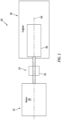
- is a schematic illustration of a powerplant.
- FIG. 2
- is a sectional schematic illustration of an internal combustion engine.
- FIG. 3
- is a sectional illustration of a portion of the engine with an ignition system.
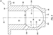
- FIG. 4
- is a sectional illustration of a first component of the ignition system.
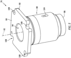
- FIG. 5
- is a perspective illustration of the first component.
- FIG. 6
- is a sectional illustration of a second component of the ignition system.
- FIG. 7
- is a perspective illustration of the second component.
- FIG. 8
- is a sectional illustration of a portion of the engine with another ignition system.
-
FIG. 1 illustrates apowerplant 20 for an aircraft. This aircraft may be configured as an airplane, a rotorcraft, a drone (e.g., an unmanned aerial vehicle (UAV)) or any other manned or unmanned aerial vehicle. Thepowerplant 20 ofFIG. 1 includes amechanical load 22, adrivetrain 24 and an internal combustion (IC)engine 26, where thedrivetrain 24 mechanically couples themechanical load 22 to theengine 26. - The
mechanical load 22 may be configured as or otherwise include arotor 28 mechanically driven by theengine 26 through thedrivetrain 24. This drivenrotor 28 may be a bladed propulsor rotor where thepowerplant 20 is configured as or otherwise includes a propulsion system for the aircraft. The propulsor rotor may be an open (e.g., un-ducted) rotor for the aircraft such as, but not limited to, a propeller rotor or a rotorcraft rotor (e.g., a main helicopter rotor). Alternatively, the propulsor rotor may be a ducted rotor for the aircraft such as, but not limited to, a fan rotor. Still alternatively, the drivenrotor 28 may be a generator rotor in an electrical power generator where thepowerplant 20 is configured as or otherwise includes an auxiliary power unit (APU) for the aircraft. The present disclosure, however, is not limited to the foregoing exemplary driven rotor configurations. Furthermore, the present disclosure is not limited to aircraft applications. Thepowerplant 20, for example, may alternatively be configured as a ground-based electrical generator or a powerplant for a ground vehicle. - The
drivetrain 24 may be configured as a direct-drive drivetrain. With such a configuration, the drivenrotor 28 is operable to rotate at a common (the same) rotational speed as a rotatingstructure 30 of theengine 26. Alternatively, thedrivetrain 24 may be configured as a geared drivetrain. With such a configuration, the drive rotor is operable to rotate as a different (e.g., fastener or slower) rotational speed than the rotatingstructure 30. Thedrivetrain 24, for example, may include ageartrain 32 and/or another transmission device coupled between the drivenrotor 28 and the rotatingstructure 30. - The
engine 26 may be configured as a rotary engine such as, but not limited to, a Wankel engine. Theengine 26 ofFIG. 2 , for example, includes anengine housing 34, anengine rotor 36, aprimary fuel injector 38 and anignition system 40. - The
housing 34 ofFIG. 2 includes aninternal housing cavity 42, a primaryfuel injector receptacle 44, anintake passage 46 and anexhaust passage 48. Thehousing 34 is also configured for mating with theignition system 40 as described below in further detail. Thehousing cavity 42 is formed within and enclosed by thehousing 34. The primaryfuel injector receptacle 44 extends through asidewall 50 of thehousing 34 from anexterior 52 of thehousing 34 to thehousing cavity 42. Theintake passage 46 extends from an inlet into theengine 26, through thehousing sidewall 50, to thehousing cavity 42, which engine inlet may also be an inlet to the powerplant 20 (seeFIG. 1 ). Theexhaust passage 48 extend from thehousing cavity 42, through thehousing sidewall 50, to an exhaust from theengine 26, which engine exhaust may also be an exhaust from the powerplant 20 (seeFIG. 1 ). - The
rotor 36 ofFIG. 2 is disposed within thehousing cavity 42, where thehousing sidewall 50 extends circumferentially around an outer periphery of therotor 36. Therotor 36 is coupled to and rotatable with the rotatingstructure 30. However, therotor 36 ofFIG. 2 is eccentric to the rotatingstructure 30. Acenterline 54 of therotor 36, for example, is parallel with, but offset from, acenterline 56 of the rotatingstructure 30, where therotor centerline 54 is also a rotational axis of therotor 36 and/or where the rotatingstructure centerline 56 is also a rotational axis of the rotatingstructure 30. With this arrangement, as therotor 36 rotates about itsrotor centerline 54, therotor centerline 54 moves (e.g., circles) about the rotatingstructure centerline 56. - The
rotor 36 may have a non-circular, lobed cross-sectional geometry when viewed, for example, in a reference plane perpendicular to therotor centerline 54. Therotor 36 ofFIG. 2 , for example, includes a plurality of (e.g., arcuate, convex) peripheral rotor faces 58 arranged circumferentially about therotor centerline 54. Each circumferentially neighboring (e.g., adjacent) pair of the rotor faces 58 meets at arespective apex 60 of therotor 36. Therotor 36 may also include one or more rotor seals 62, where eachrotor seal 62 is arranged at (e.g., on, adjacent or proximate) a respective one of the rotor apexes 60. Eachrotor seal 62 is configured to sealingly engage (e.g., contact) and thereby form a seal interface with an interior 64 of thehousing sidewall 50. - The
rotor 36 and thehousing 34 may collectively form one ormore combustion volumes 66A-C (generally referred to as "66") (e.g., combustion chambers, working volumes, etc.) within thehousing 34. Each combustion volume 66, in particular, is formed by and between a respective one of the rotor faces 58 and a corresponding (albeit changing) portion of thehousing sidewall 50, and circumferentially between a respective neighboring pair of the rotor seals 62. Each of the combustion volumes 66 moves about thecenterline rotor 36 eccentrically rotates within thehousing 34 and itshousing cavity 42. With the rotor position ofFIG. 2 , thecombustion volume 66A is fluidly coupled with the intake passage 46 (and fluidly decoupled from the exhaust passage 48), thecombustion volume 66B is fluidly coupled with the exhaust passage 48 (and fluidly decoupled from the intake passage 46), and thecombustion volume 66C is fluidly decoupled from theintake passage 46 and theexhaust passage 48. - The
primary fuel injector 38 is mated with / received within the primaryfuel injector receptacle 44. Theprimary fuel injector 38, for example, projects into the primaryfuel injector receptacle 44 and is threaded into or otherwise attached to thehousing 34. - The
ignition system 40 is attached to thehousing 34 as described below in further detail. - During engine operation, air is directed through the
intake passage 46 into a respective one of the combustion volumes 66. As therotor 36 rotates within thehousing 34, a volumetric measure of the respective combustion volume 66 decreases thereby compressing the air within that combustion volume 66. Theprimary fuel injector 38 directs (e.g., injects) primary fuel into the respective combustion volume 66 to mix with the air as it is being compressed to provide a fuel-air mixture. When the respective combustion volume 66 aligns with theignition system 40, the fuel-air mixture within that combustion volume 66 is ignited to generate combustion products. As therotor 36 continues to rotate within thehousing 34, the volumetric measure of the respective combustion volume 66 increases thereby facilitating expansion of the combustion products within the respective combustion volume 66 until those expanded combustion products are exhausted from theengine 26 through theexhaust passage 48. The expansion of the combustion products within the respective combustion volume 66 drives rotation of therotor 36 within thehousing 34. The rotation of therotor 36 and, thus, the rotation of the rotatingstructure 30 in turn drives rotation of the drivenrotor 28 ofFIG. 1 through thedrivetrain 24. - Referring to
FIG. 2 , to ignite the fuel-air mixture within one of the combustion volumes 66, theignition system 40 is configured to introduce a flame (e.g., a pilot flame) and/or relatively hot combustion products into the respective combustion volume 66. Theignition system 40 ofFIG. 2 , for example, includes a pilot chamber structure 68 ("pilot structure") (schematically shown), a pilot fuel injector 70 ("pilot injector") and a pilot ignitor 72 (e.g., a spark plug, a glow plug, etc.). Thepilot structure 68 includes an internal pilot chamber 74 (e.g., a sub-chamber, a pre-ignition chamber, etc.) and a pilot aperture 76 (e.g., a transfer hole) which fluidly couples thepilot chamber 74 to the respective combustion volume 66. Thepilot injector 70 is configured to direct (e.g., inject) pilot fuel into thepilot chamber 74. Thepilot ignitor 72 is configured to ignite the pilot fuel within thepilot chamber 74 to generate the pilot flame and/or the pilot combustion products. The pilot flame and/or the pilot combustion products are directed through thepilot aperture 76 into the respective combustion volume 66 to ignite the fuel-air mixture within that combustion volume 66. - The combustion of the pilot fuel within the
pilot chamber 74 may be continuous (e.g., sustained) throughout an engine cycle. Here, the term "engine cycle" may describe a cycle as therotor 36 makes a complete rotation about therotor centerline 54 within thehousing 34. The continuous combustion within thepilot chamber 74 may subject thepilot structure 68 to relatively high thermal loads, particularly a portion of thepilot chamber 74 adjacent and partially forming the respective combustion volume 66. Such high thermal loads may cause relatively high compressive stresses within thepilot structure 68 which may affect pilot structure durability. Moreover, the high thermal loads paired with a relatively high velocity fluid flow associated with directing the flame and/or the combustion products through thepilot aperture 76 into the respective combustion volume 66 may erode material of thepilot structure 68 forming thepilot aperture 76. - To increase pilot structure durability, the
pilot structure 68 may be manufactured from ceramic such as, but not limited to, SiN or SiC ceramic material. However, casting or sintering a single monolithic ceramic body with an embedded chamber may be difficult. Furthermore, even where a single monolithic ceramic body with an embedded chamber can be formed, it may be difficult to finish surface(s) forming the embedded chamber due to minimal (if any) tool access into the chamber. Therefore, referring toFIG. 3 , thepilot structure 68 may be formed as a multicomponent structure. Thepilot structure 68 ofFIG. 3 , for example, includes a first component 78 (e.g., an inner and/or base structure) and a second component 80 (e.g., an outer and/or plug structure). - Referring to
FIG. 4 , thefirst component 78 extends longitudinally along alongitudinal centerline 82 between and to anouter end 84 of thefirst component 78 and a distalinner end 86 of thefirst component 78. Thislongitudinal centerline 82 may be a centerline of thepilot structure 68 and/or one or more of itscomponents 78 and/or 80 (see alsoFIG. 6 ). Thefirst component 78 ofFIG. 4 includes a first component base 88 ("first base") and a first component mount 90 ("first mount") connected to (e.g., formed integral with) thefirst base 88. - The
first base 88 projects longitudinally along thelongitudinal centerline 82 from the first componentouter end 84 to the first componentinner end 86. Thefirst base 88 includes aninternal chamber cavity 92, asecond component receptacle 94 and thepilot aperture 76. - The
chamber cavity 92 is disposed (e.g., completely) within thefirst base 88 proximate the first componentinner end 86, and longitudinally between thesecond component receptacle 94 and thepilot aperture 76. Thesecond component receptacle 94 projects longitudinally along thelongitudinal centerline 82 into thefirst base 88 from the first componentouter end 84 to thechamber cavity 92. Thesecond component receptacle 94 may be cylindrical with a uniform (e.g., constant) lateral receptacle width 96 (e.g., diameter) along its longitudinal length. Alateral cavity width 98 of thechamber cavity 92, on the other hand, may change along its longitudinal length. Thelateral cavity width 98 may have a (e.g., maximum) value that is larger than a value of thelateral receptacle width 96 at a longitudinal interface between thechamber cavity 92 and thesecond component receptacle 94. With this arrangement, a (e.g., annular)portion 97 of thechamber cavity 92 extends partially laterally (e.g., radially) into and longitudinally within asidewall 100 of thefirst component 78 and itsfirst base 88. A portion of thefirst base 88 and itsfirst sidewall 100 at the interface may thereby partially laterally overhang thechamber cavity 92. - The
pilot aperture 76 extends through anendwall 102 of thefirst component 78 and itsfirst base 88 from thechamber cavity 92 to the first componentinner end 86. A centerline of thepilot aperture 76 may be angularly offset from thelongitudinal centerline 82 by a non-zero acute angle. The present disclosure, however, is not limited to such an exemplary angularly offset pilot aperture arrangement. - The
first base 88 may also include afuel aperture 104 and at least oneignitor aperture 106. Each of theseapertures first sidewall 100 to thechamber cavity 92. Thefuel aperture 104 and theignitor aperture 106 may be disposed on opposing lateral sides of thechamber cavity 92. - The
first mount 90 is disposed at the first componentouter end 84. Thefirst mount 90 extends circumferentially about (e.g., completely around) thefirst base 88. Thefirst mount 90 projects laterally out from thefirst base 88 to a lateral outer periphery of thefirst mount 90. Referring toFIG. 5 , this lateral outer periphery of thefirst mount 90 may have a substantially polygonal (e.g., square) shape when viewed, for example, in a reference plane perpendicular to thelongitudinal centerline 82. Thefirst mount 90 may include one or morefirst fastener apertures 108; e.g., slots. Eachfirst fastener aperture 108 is disposed at a respective corner of thefirst mount 90. Eachfirst fastener aperture 108 ofFIG. 5 projects laterally into and longitudinally through thefirst mount 90. It is contemplated, however, one or more of thefirst fastener apertures 108 may each alternatively be configured as a through hole. - Referring to
FIG. 4 , thefirst component 78 may be formed from the ceramic material. Thefirst component 78, for example, may be cast, sintered and/or otherwise formed as a monolithic body of the ceramic. Since thechamber cavity 92 is open by way of thesecond component receptacle 94 to an exterior of thefirst component 78, one or more tools may be inserted into thechamber cavity 92 through thesecond component receptacle 94 to provide asurface 110 forming thechamber cavity 92 with a prescribed surface finish. Thecavity surface 110, in order words, may be subject to one or more finishing operations such as grinding, sanding, polishing, coating, etc. - Referring to
FIG. 6 , thesecond component 80 extends longitudinally along thelongitudinal centerline 82 between and to anouter end 112 of thesecond component 80 and aninner end 114 of thesecond component 80. Thesecond component 80 ofFIG. 6 includes a second component base 116 ("second base") and a second component mount 118 ("second mount") connected to (e.g., formed integral with) thesecond base 116. - The
second base 116 projects longitudinally along thelongitudinal centerline 82 from the second componentouter end 112 to the second componentinner end 114. Thesecond base 116 includes achamber recess 120 at the second componentinner end 114. Thischamber recess 120 extends partially longitudinally into thesecond base 116 from the second componentinner end 114. Thesecond base 116 may also include a (e.g., weight-reduction) bore 122 at the first componentinner end 86. This bore 122 extends partially longitudinally into thesecond base 116 from the second componentouter end 112, where anendwall 124 of thesecond base 116 may completely separate thebore 122 from thechamber recess 120. - The
second mount 118 is disposed at the second componentouter end 112. Thesecond mount 118 extends circumferentially about (e.g., completely around) thesecond base 116. Thesecond mount 118 projects laterally out from thesecond base 116 to a lateral outer periphery of thesecond mount 118. Referring toFIG. 7 , this lateral outer periphery of thesecond mount 118 may have a substantially polygonal (e.g., square) shape when viewed, for example, in a reference plane perpendicular to thelongitudinal centerline 82. Thesecond mount 118 may include one or moresecond fastener apertures 126; e.g., through-holes. Eachsecond fastener aperture 126 is disposed at a respective corner of thesecond mount 118. Eachsecond fastener aperture 126 ofFIG. 7 projects longitudinally through thesecond mount 118. It is contemplated, however, one or more of thesecond fastener apertures 126 may each alternatively be configured as a slot. - Referring to
FIG. 6 , thesecond component 80 may be formed from metal or ceramic, which ceramic may be the same as or different than the ceramic material forming thefirst component 78. Thesecond component 80, for example, may be cast, sintered and/or otherwise formed as a monolithic body of the metal or the ceramic material. Since thechamber recess 120 is open at the second componentinner end 114, one or more tools may be inserted into thechamber recess 120 to provide asurface 128 forming thechamber recess 120 with a prescribed surface finish. Therecess surface 128, in order words, may be subject to one or more finishing operations such as grinding, sanding, polishing, coating, etc. - Referring to
FIG. 3 , thefirst component 78 is mated with (e.g., plugged into) thehousing 34 and apilot structure receptacle 130 in thehousing 34. Thepilot structure receptacle 130 ofFIG. 3 projects longitudinally through thehousing sidewall 50 from thehousing exterior 52 to thehousing cavity 42. The entirefirst component 78 may be disposed within thepilot structure receptacle 130. Thefirst base 88 projects longitudinally within thepilot structure receptacle 130 to thehousing cavity 42 / the respective combustion volume 66. Thefirst mount 90 is seated longitudinally against a (e.g., annular)shoulder 132 of thehousing 34 within thepilot structure receptacle 130. A first seal element 134 (e.g., a ring seal element) may be disposed longitudinally between and engage (e.g., contact) thefirst mount 90 and thehousing 34. - The entire
second component 80 may also be disposed within thepilot structure receptacle 130. Thesecond component 80 is mated with (e.g., plugged into) thefirst component 78 and itssecond component receptacle 94. Thesecond base 116, for example, projects longitudinally through thesecond component receptacle 94 to thechamber cavity 92. Thesecond mount 118 is seated longitudinally against thefirst mount 90 within thepilot structure receptacle 130. A second seal element 136 (e.g., a ring seal element) may be disposed longitudinally between and engage (e.g., contact) thefirst mount 90 and thesecond mount 118. Thesecond component 80 and itssecond mount 118 may be mechanically fastened to thehousing 34 using one ormore fasteners 138; e.g., bolts. Eachbolt 138, for example, may extend sequentially through a respective one of the second fastener apertures 126 (seeFIG. 7 ), a respective one of the first fastener apertures 108 (seeFIG. 5 ) and into a respective threaded fastener aperture in thehousing 34. Thefirst component 78 and itsfirst mount 90 may thereby also be secured to thehousing 34; e.g., clamped or otherwise retained longitudinally between thesecond component 80 and itssecond mount 118 and thehousing 34. - With the above pilot structure arrangement, the
pilot chamber 74 is formed by and longitudinally between thefirst component 78 and thesecond component 80 within thepilot structure 68. In particular, thechamber cavity 92 forms a first portion of thepilot chamber 74 and thechamber recess 120 forms a second portion of thepilot chamber 74. However, while both thefirst component 78 and thesecond component 80 collectively form thepilot chamber 74, thefirst component 78 and itschamber cavity 92 may be configured to form a majority (more than fifty percent) of a volume of thepilot chamber 74; e.g., more than sixty percent (60%), seventy percent (70%) or even eighty percent (80%) of thepilot chamber 74. Note, the greater the percentage of thepilot chamber 74 formed by thefirst component 78, the greater percentage of thepilot chamber 74 formed by the ceramic material where, for example, thesecond component 80 is formed from metal. - The
pilot chamber 74 ofFIG. 3 is configured with a spherical geometry. Thecavity surface 110 and/or therecess surface 128, for example, may each be configured as a partial spherical surface. The present disclosure, however, is not limited to such an exemplary pilot chamber geometry. Thepilot chamber 74, for example, may alternatively be configured with a cylindrical geometry, a frustoconical geometry, etc.; however, the spherical geometry may facilitate a compact and durable pilot structure. - The
pilot injector 70 ofFIG. 3 is attached to thehousing 34. Thispilot injector 70 is configured to direct the pilot fuel into thepilot chamber 74 through thefuel aperture 104 in thepilot structure 68 and itsfirst component 78. Thepilot ignitor 72 ofFIG. 3 is attached to thehousing 34. Thispilot injector 70 is received in (e.g., projects into or through) theignitor aperture 106 in thepilot structure 68 and itsfirst component 78. Thepilot ignitor 72 may thereby extend to or into thepilot chamber 74 for igniting the pilot fuel within thepilot chamber 74. - To shield the
pilot structure 68 from an environment and/or other components outside of theengine 26 and itshousing 34, a cover 140 (e.g., a cover plate) is secured to thehousing 34. Thecover 140 covers (e.g., blocks, overlaps, etc.) an opening to thepilot structure receptacle 130 into thehousing 34. Thecover 140 may thereby enclose thepilot structure 68 and its components (e.g., 78 and 80) within thehousing 34 and itspilot structure receptacle 130. Thecover 140 ofFIG. 3 , in particular, is mechanically fastened to thehousing 34 with one ormore fasteners 142; e.g., bolts. - The
pilot structure 68 ofFIG. 3 is configured to be installed with and/or removed from theengine 26 and its housing 34 (e.g., completely) from an exterior of theengine 26 and itshousing 34. Thus, assembly and/or maintenance personnel may not need access to an interior of theengine 26 and itshousing 34 for pilot structure installation, inspection and/or removal. Removing thepilot structure 68 may also facilitate inspection of one or more elements internal to theengine 26; e.g., therotor seal 62 ofFIG. 2 , theinterior 64 of thehousing sidewall 50 ofFIG. 2 , the rotor faces 58 ofFIG. 2 , etc. This may simplify engine assembly, inspection and/or maintenance. - In some embodiments, referring to
FIG. 3 , thefirst component 78 and thesecond component 80 may configured for individual installation with and/or removal from theengine 26 and itshousing 34. In other embodiments, referring toFIG. 8 , thefirst component 78 and thesecond component 80 may be installed with and/or removed from theengine 26 and itshousing 34 as a unit. In particular, thepilot structure 68 ofFIG. 8 is configured as or otherwise includes a pilot chamber module 144. This pilot chamber module 144 includes thefirst component 78, thesecond component 80 and a support ring 146 (e.g., a retainer). Thefirst component 78 and thesecond component 80 may each have a similar configuration as generally described above with reference toFIGS. 3-7 . However, rather than retaining (e.g., clamping) thefirst component 78 between thesecond component 80 and thehousing 34 as shown inFIG. 3 , thefirst component 78 ofFIG. 8 and itsfirst mount 90 are retained longitudinally between thesecond component 80 and itssecond mount 118 and thesupport ring 146. In particular, thefirst mount 90 is longitudinally clamped between aninner rim 148 of thesupport ring 146 and thesecond mount 118. Thesecond component 80 and itssecond mount 118 may be mechanically attached to thesupport ring 146 through a threadedinterface 150 between thesecond component 80 and thesupport ring 146. Thesecond component 80 and itssecond mount 118, for example, may be threaded into a threaded aperture of thesupport ring 146. This assembled pilot chamber module 144 may then be installed with thehousing 34 as a single unit. The pilot chamber module 144 and itssupport ring 146, for example, may be clamped or otherwise retained longitudinally between thecover 140 and thehousing 34, where thecover 140 may be mechanically fastened to thehousing 34 by the fastener(s) 142. - To seal the
pilot structure 68, thefirst seal element 134 ofFIG. 8 may be disposed longitudinally between and engage thesupport ring 146 and thehousing 34, laterally adjacent thefirst component 78. Thesecond seal element 136 ofFIG. 8 may be disposed longitudinally between and engage thesecond component 80 and itssecond mount 118 and thesupport ring 146. - In the embodiment of
FIG. 8 , both thesecond component 80 and thesupport ring 146 may be formed from the metal to facilitate the threadedinterface 150 therebetween. It is contemplated, however, thesecond component 80 may be otherwise secured to thesupport ring 146. In such embodiments, it is also contemplated thesecond component 80 and/or thesupport ring 146 may be formed from the ceramic material. - While the
first component 78 is described above as being formed from ceramic, the present disclosure is not limited to such an exemplary construction. It is contemplated, for example, thefirst component 78 may alternatively be formed from metal (or another high temperature material) where, for example, thecavity surface 110 is coated with a thermal barrier layer. - The
ignition system 40 is described above with reference to the rotary engine; e.g., the Wankel engine. It is contemplated, however, theignition system 40 may alternatively be configured with various other types of engines such as a reciprocating piston engine or a gas turbine engine. The present disclosure therefore is not limited to any particular engine types or configurations. - While various embodiments of the present disclosure have been described, it will be apparent to those of ordinary skill in the art that many more embodiments and implementations are possible within the scope of the disclosure. For example, the present disclosure as described herein includes several aspects and embodiments that include particular features. Although these features may be described individually, it is within the scope of the present disclosure that some or all of these features may be combined with any one of the aspects and remain within the scope of the disclosure. Accordingly, the present disclosure is not to be restricted except in light of the attached claims and their equivalents.
Claims (15)
- An assembly for a powerplant (20), comprising:a housing (34) forming a combustion volume (66) within the housing (34);a primary fuel injector (38) configured to inject primary fuel into the combustion volume (66); andan ignition system (40) configured to ignite the primary fuel within the combustion volume (66), the ignition system (40) including a pilot fuel injector (70), a pilot ignitor (72), a pilot chamber (74), a first component (78) and a second component (80), wherein:the pilot fuel injector (70) is configured to inject pilot fuel into the pilot chamber (74);the pilot ignitor (72) is configured to ignite the pilot fuel within the pilot chamber (74);the pilot chamber (74) is fluidly coupled with the combustion volume (66) through an aperture (76) in the first component (78), and the pilot chamber (74) is formed by and disposed between the first component (78) and the second component (80); andthe first component (78) comprises a ceramic.
- The assembly of claim 1, wherein the second component (80) comprises a metal.
- The assembly of claim 1 or 2, wherein the pilot chamber (74) has a spherical geometry.
- The assembly of any preceding claim, wherein a majority of a volume of the pilot chamber (74) is formed within the first component (78).
- The assembly of any preceding claim, wherein:the first component (78) extends longitudinally along a centerline (82) towards the combustion volume (66); anda portion (92) of the pilot chamber (74) extends laterally into and longitudinally within a sidewall (100) of the first component (78).
- The assembly of any preceding claim, wherein:the first component (78) includes a cavity (92) and a receptacle (94);the cavity (92) forms at least a portion of the pilot chamber (74) within the first component (78);the receptacle (94) extends longitudinally into the first component (78) to the cavity (92); andthe second component (80) projects longitudinally into the receptacle (94) to the pilot chamber (74),optionally wherein:the second component (80) includes a recess (120) at a distal end of the second component (80); andthe recess (120) forms a portion of the pilot chamber (74) within the second component (80).
- The assembly of claim 6, wherein:the cavity (92) has a lateral cavity width (98); andthe receptacle (94) has a lateral receptacle width (96) at a longitudinal interface between the receptacle (94) and the cavity (92), and the lateral receptacle width (96) is smaller than the lateral cavity width (98).
- The assembly of claim 6 or 7, wherein:a second receptacle (130) extends longitudinally into the housing (34) from an exterior (52) of the housing (34) to the combustion volume (66); andthe first component (78) is disposed within the second receptacle (130) and projects longitudinally to the combustion volume (66),optionally wherein the assembly further comprises a cover (140) secured to the housing (34) and enclosing the first component (78) and the second component (80) within the second receptacle (130).
- The assembly of any preceding claim, wherein:the second component (80) is fastened to the housing (34) by one or more fasteners (138); andthe first component (78) is clamped between the second component (80) and the housing (34).
- The assembly of any preceding claim, further comprising:a first seal element (134) engaged with and between the first component (78) and the housing (34); and/ora second seal element (136) engaged with and between the first component (78) and the second component (80).
- The assembly of any of claims 1 to 8, further comprising a pilot chamber module (144) including the first component (78), the second component (80) and a support ring (146), wherein:the second component (80) fastened to the support ring (146); andthe first component (78) is clamped between the second component (80) and the support ring (146),optionally wherein the second component (80) is threaded into the support ring (146).
- The assembly of claim 11, further comprising:a first seal element (134) engaged with and between the support ring (146) and the housing (34); and/ora second seal element (136) engaged with and between the second component (80) and the support ring (146).
- The assembly of claim 11 or 12, further comprising a cover (140) over the pilot chamber module (144), wherein:the cover (140) is fastened to the housing (34) by one or more fasteners (142); andthe pilot chamber module (144) is clamped between the cover (140) and the housing (34).
- The assembly of any preceding claim, wherein:the pilot fuel injector (70) is configured to inject the pilot fuel into the pilot chamber (74) through a fuel aperture (104) in the first component (78); and/orthe pilot ignitor (72) is received in an ignitor aperture (106) in the first component (78).
- The assembly of any preceding claim, comprising a rotary engine (26) that includes the housing (34), the primary fuel injector (38) and the ignition system (40).
Applications Claiming Priority (1)
| Application Number | Priority Date | Filing Date | Title |
|---|---|---|---|
| US18/135,575 US12117173B1 (en) | 2023-04-17 | 2023-04-17 | Internal combustion engine with ceramic pilot chamber component(s) |
Publications (2)
| Publication Number | Publication Date |
|---|---|
| EP4450784A1 true EP4450784A1 (en) | 2024-10-23 |
| EP4450784B1 EP4450784B1 (en) | 2026-03-11 |
Family
ID=90789488
Family Applications (1)
| Application Number | Title | Priority Date | Filing Date |
|---|---|---|---|
| EP24170893.2A Active EP4450784B1 (en) | 2023-04-17 | 2024-04-17 | Internal combustion engine with ceramic pilot chamber component(s) |
Country Status (3)
| Country | Link |
|---|---|
| US (1) | US12117173B1 (en) |
| EP (1) | EP4450784B1 (en) |
| CA (1) | CA3235413A1 (en) |
Citations (4)
| Publication number | Priority date | Publication date | Assignee | Title |
|---|---|---|---|---|
| JPS49124407A (en) * | 1972-08-16 | 1974-11-28 | ||
| AT413855B (en) * | 2003-05-27 | 2006-06-15 | Avl List Gmbh | Internal combustion engine |
| EP2205840B1 (en) * | 2007-11-09 | 2012-02-22 | Wärtsilä Finland Oy | Prechamber arrangement of a combustion engine |
| US9528434B1 (en) * | 2011-07-28 | 2016-12-27 | Pratt & Whitney Canada Corp. | Rotary internal combustion engine with pilot subchamber |
Family Cites Families (6)
| Publication number | Priority date | Publication date | Assignee | Title |
|---|---|---|---|---|
| JPS6193227A (en) | 1984-10-11 | 1986-05-12 | Mazda Motor Corp | Manufacturing method of engine subchamber |
| US5715787A (en) | 1995-10-31 | 1998-02-10 | Isuzu Ceramics Research Institute Co., Ltd | Internal-combustion engine having a pre-combustion chamber |
| US5915351A (en) | 1997-02-24 | 1999-06-29 | Chrysler Corporation | Insulated precombustion chamber |
| US9038594B2 (en) * | 2011-07-28 | 2015-05-26 | Pratt & Whitney Canada Corp. | Rotary internal combustion engine with pilot subchamber |
| US9121277B2 (en) * | 2012-02-06 | 2015-09-01 | Pratt & Whitney Canada Corp. | Rotary internal combustion engine with cooled insert |
| US10041402B2 (en) | 2016-05-12 | 2018-08-07 | Pratt & Whitney Canada Corp. | Internal combustion engine with split pilot injection |
-
2023
- 2023-04-17 US US18/135,575 patent/US12117173B1/en active Active
-
2024
- 2024-04-16 CA CA3235413A patent/CA3235413A1/en active Pending
- 2024-04-17 EP EP24170893.2A patent/EP4450784B1/en active Active
Patent Citations (4)
| Publication number | Priority date | Publication date | Assignee | Title |
|---|---|---|---|---|
| JPS49124407A (en) * | 1972-08-16 | 1974-11-28 | ||
| AT413855B (en) * | 2003-05-27 | 2006-06-15 | Avl List Gmbh | Internal combustion engine |
| EP2205840B1 (en) * | 2007-11-09 | 2012-02-22 | Wärtsilä Finland Oy | Prechamber arrangement of a combustion engine |
| US9528434B1 (en) * | 2011-07-28 | 2016-12-27 | Pratt & Whitney Canada Corp. | Rotary internal combustion engine with pilot subchamber |
Also Published As
| Publication number | Publication date |
|---|---|
| US20240344700A1 (en) | 2024-10-17 |
| CA3235413A1 (en) | 2025-06-17 |
| US12117173B1 (en) | 2024-10-15 |
| EP4450784B1 (en) | 2026-03-11 |
Similar Documents
| Publication | Publication Date | Title |
|---|---|---|
| US10557407B2 (en) | Rotary internal combustion engine with pilot subchamber | |
| EP2687675B1 (en) | Compound cycle engine | |
| EP2551448B1 (en) | Rotary internal combustion engine with pilot subchamber and method of injecting fuel | |
| EP2775117B1 (en) | Rotary internal combustion engine with pilot subchamber | |
| US20170218760A1 (en) | Engine assembly with turbine support casing | |
| EP3299607B1 (en) | Method of operating an engine having a pilot subchamber at partial load conditions | |
| US10801394B2 (en) | Rotary engine with pilot subchambers | |
| CA2956598C (en) | Inlet guide assembly | |
| EP4450784B1 (en) | Internal combustion engine with ceramic pilot chamber component(s) | |
| EP4491846A2 (en) | Rotary engine housing with a seal assembly | |
| EP4491847A2 (en) | Rotary engine housing with a seal assembly | |
| US12123343B1 (en) | Internal combustion engine with coated ignition system component(s) | |
| EP4589118A1 (en) | Rotary engine with side housing having a side plate with a ceramic matrix composite core | |
| US5088285A (en) | Internal combustion engine | |
| ES2877173T3 (en) | Rotary internal combustion engine with unequal volumetric ratios | |
| EP4442958B1 (en) | Rotor assembly for a rotary engine | |
| US12168933B1 (en) | Impingement cooling assembly for an aircraft rotary engine housing | |
| EP4442957B1 (en) | Rotor for a rotary engine | |
| US20260098485A1 (en) | Powerplant jacking insert with exterior and interior threads | |
| CA3254169A1 (en) | Impingement cooling assembly for an aircraft rotary engine housing | |
| RU2015374C1 (en) | Rotary-vane engine | |
| EP3650672A2 (en) | Method and system for starting a turbocompounded engine | |
| EP0307515A1 (en) | Rotary internal combustion engine |
Legal Events
| Date | Code | Title | Description |
|---|---|---|---|
| PUAI | Public reference made under article 153(3) epc to a published international application that has entered the european phase |
Free format text: ORIGINAL CODE: 0009012 |
|
| STAA | Information on the status of an ep patent application or granted ep patent |
Free format text: STATUS: THE APPLICATION HAS BEEN PUBLISHED |
|
| AK | Designated contracting states |
Kind code of ref document: A1 Designated state(s): AL AT BE BG CH CY CZ DE DK EE ES FI FR GB GR HR HU IE IS IT LI LT LU LV MC ME MK MT NL NO PL PT RO RS SE SI SK SM TR |
|
| STAA | Information on the status of an ep patent application or granted ep patent |
Free format text: STATUS: REQUEST FOR EXAMINATION WAS MADE |
|
| 17P | Request for examination filed |
Effective date: 20250423 |
|
| RIC1 | Information provided on ipc code assigned before grant |
Ipc: F02B 19/10 20060101AFI20250714BHEP Ipc: F02B 19/16 20060101ALI20250714BHEP Ipc: F02B 53/12 20060101ALN20250714BHEP |
|
| GRAP | Despatch of communication of intention to grant a patent |
Free format text: ORIGINAL CODE: EPIDOSNIGR1 |
|
| STAA | Information on the status of an ep patent application or granted ep patent |
Free format text: STATUS: GRANT OF PATENT IS INTENDED |
|
| RIC1 | Information provided on ipc code assigned before grant |
Ipc: F02B 19/10 20060101AFI20250912BHEP Ipc: F02B 19/16 20060101ALI20250912BHEP Ipc: F02B 53/12 20060101ALN20250912BHEP |
|
| INTG | Intention to grant announced |
Effective date: 20250930 |
|
| GRAS | Grant fee paid |
Free format text: ORIGINAL CODE: EPIDOSNIGR3 |
|
| GRAA | (expected) grant |
Free format text: ORIGINAL CODE: 0009210 |
|
| STAA | Information on the status of an ep patent application or granted ep patent |
Free format text: STATUS: THE PATENT HAS BEEN GRANTED |
|
| AK | Designated contracting states |
Kind code of ref document: B1 Designated state(s): AL AT BE BG CH CY CZ DE DK EE ES FI FR GB GR HR HU IE IS IT LI LT LU LV MC ME MK MT NL NO PL PT RO RS SE SI SK SM TR |
|
| REG | Reference to a national code |
Ref country code: CH Ref legal event code: F10 Free format text: ST27 STATUS EVENT CODE: U-0-0-F10-F00 (AS PROVIDED BY THE NATIONAL OFFICE) Effective date: 20260311 Ref country code: GB Ref legal event code: FG4D |
|
| REG | Reference to a national code |
Ref country code: DE Ref legal event code: R096 Ref document number: 602024003063 Country of ref document: DE |
|
| REG | Reference to a national code |
Ref country code: IE Ref legal event code: FG4D |