EP4450764A1 - Composite guide vane with insert - Google Patents
Composite guide vane with insert Download PDFInfo
- Publication number
- EP4450764A1 EP4450764A1 EP24166898.7A EP24166898A EP4450764A1 EP 4450764 A1 EP4450764 A1 EP 4450764A1 EP 24166898 A EP24166898 A EP 24166898A EP 4450764 A1 EP4450764 A1 EP 4450764A1
- Authority
- EP
- European Patent Office
- Prior art keywords
- composite
- insert
- guide vane
- laminate
- end portion
- Prior art date
- Legal status (The legal status is an assumption and is not a legal conclusion. Google has not performed a legal analysis and makes no representation as to the accuracy of the status listed.)
- Pending
Links
Images



Classifications
-
- F—MECHANICAL ENGINEERING; LIGHTING; HEATING; WEAPONS; BLASTING
- F01—MACHINES OR ENGINES IN GENERAL; ENGINE PLANTS IN GENERAL; STEAM ENGINES
- F01D—NON-POSITIVE DISPLACEMENT MACHINES OR ENGINES, e.g. STEAM TURBINES
- F01D5/00—Blades; Blade-carrying members; Heating, heat-insulating, cooling or antivibration means on the blades or the members
- F01D5/12—Blades
- F01D5/28—Selecting particular materials; Particular measures relating thereto; Measures against erosion or corrosion
- F01D5/282—Selecting composite materials, e.g. blades with reinforcing filaments
-
- B—PERFORMING OPERATIONS; TRANSPORTING
- B32—LAYERED PRODUCTS
- B32B—LAYERED PRODUCTS, i.e. PRODUCTS BUILT-UP OF STRATA OF FLAT OR NON-FLAT, e.g. CELLULAR OR HONEYCOMB, FORM
- B32B3/00—Layered products comprising a layer with external or internal discontinuities or unevennesses, or a layer of non-planar shape; Layered products comprising a layer having particular features of form
- B32B3/26—Layered products comprising a layer with external or internal discontinuities or unevennesses, or a layer of non-planar shape; Layered products comprising a layer having particular features of form characterised by a particular shape of the outline of the cross-section of a continuous layer; characterised by a layer with cavities or internal voids ; characterised by an apertured layer
- B32B3/263—Layered products comprising a layer with external or internal discontinuities or unevennesses, or a layer of non-planar shape; Layered products comprising a layer having particular features of form characterised by a particular shape of the outline of the cross-section of a continuous layer; characterised by a layer with cavities or internal voids ; characterised by an apertured layer characterised by a layer having non-uniform thickness
-
- B—PERFORMING OPERATIONS; TRANSPORTING
- B32—LAYERED PRODUCTS
- B32B—LAYERED PRODUCTS, i.e. PRODUCTS BUILT-UP OF STRATA OF FLAT OR NON-FLAT, e.g. CELLULAR OR HONEYCOMB, FORM
- B32B38/00—Ancillary operations in connection with laminating processes
- B32B38/18—Handling of layers or the laminate
- B32B38/1808—Handling of layers or the laminate characterised by the laying up of the layers
-
- B—PERFORMING OPERATIONS; TRANSPORTING
- B32—LAYERED PRODUCTS
- B32B—LAYERED PRODUCTS, i.e. PRODUCTS BUILT-UP OF STRATA OF FLAT OR NON-FLAT, e.g. CELLULAR OR HONEYCOMB, FORM
- B32B5/00—Layered products characterised by the non- homogeneity or physical structure, i.e. comprising a fibrous, filamentary, particulate or foam layer; Layered products characterised by having a layer differing constitutionally or physically in different parts
- B32B5/02—Layered products characterised by the non- homogeneity or physical structure, i.e. comprising a fibrous, filamentary, particulate or foam layer; Layered products characterised by having a layer differing constitutionally or physically in different parts characterised by structural features of a fibrous or filamentary layer
-
- B—PERFORMING OPERATIONS; TRANSPORTING
- B32—LAYERED PRODUCTS
- B32B—LAYERED PRODUCTS, i.e. PRODUCTS BUILT-UP OF STRATA OF FLAT OR NON-FLAT, e.g. CELLULAR OR HONEYCOMB, FORM
- B32B5/00—Layered products characterised by the non- homogeneity or physical structure, i.e. comprising a fibrous, filamentary, particulate or foam layer; Layered products characterised by having a layer differing constitutionally or physically in different parts
- B32B5/22—Layered products characterised by the non- homogeneity or physical structure, i.e. comprising a fibrous, filamentary, particulate or foam layer; Layered products characterised by having a layer differing constitutionally or physically in different parts characterised by the presence of two or more layers which are next to each other and are fibrous, filamentary, formed of particles or foamed
- B32B5/24—Layered products characterised by the non- homogeneity or physical structure, i.e. comprising a fibrous, filamentary, particulate or foam layer; Layered products characterised by having a layer differing constitutionally or physically in different parts characterised by the presence of two or more layers which are next to each other and are fibrous, filamentary, formed of particles or foamed one layer being a fibrous or filamentary layer
- B32B5/26—Layered products characterised by the non- homogeneity or physical structure, i.e. comprising a fibrous, filamentary, particulate or foam layer; Layered products characterised by having a layer differing constitutionally or physically in different parts characterised by the presence of two or more layers which are next to each other and are fibrous, filamentary, formed of particles or foamed one layer being a fibrous or filamentary layer another layer next to it also being fibrous or filamentary
-
- F—MECHANICAL ENGINEERING; LIGHTING; HEATING; WEAPONS; BLASTING
- F01—MACHINES OR ENGINES IN GENERAL; ENGINE PLANTS IN GENERAL; STEAM ENGINES
- F01D—NON-POSITIVE DISPLACEMENT MACHINES OR ENGINES, e.g. STEAM TURBINES
- F01D9/00—Stators
- F01D9/02—Nozzles; Nozzle boxes; Stator blades; Guide conduits, e.g. individual nozzles
-
- B—PERFORMING OPERATIONS; TRANSPORTING
- B32—LAYERED PRODUCTS
- B32B—LAYERED PRODUCTS, i.e. PRODUCTS BUILT-UP OF STRATA OF FLAT OR NON-FLAT, e.g. CELLULAR OR HONEYCOMB, FORM
- B32B2260/00—Layered product comprising an impregnated, embedded, or bonded layer wherein the layer comprises an impregnation, embedding, or binder material
- B32B2260/02—Composition of the impregnated, bonded or embedded layer
- B32B2260/021—Fibrous or filamentary layer
- B32B2260/023—Two or more layers
-
- B—PERFORMING OPERATIONS; TRANSPORTING
- B32—LAYERED PRODUCTS
- B32B—LAYERED PRODUCTS, i.e. PRODUCTS BUILT-UP OF STRATA OF FLAT OR NON-FLAT, e.g. CELLULAR OR HONEYCOMB, FORM
- B32B2260/00—Layered product comprising an impregnated, embedded, or bonded layer wherein the layer comprises an impregnation, embedding, or binder material
- B32B2260/04—Impregnation, embedding, or binder material
- B32B2260/046—Synthetic resin
-
- B—PERFORMING OPERATIONS; TRANSPORTING
- B32—LAYERED PRODUCTS
- B32B—LAYERED PRODUCTS, i.e. PRODUCTS BUILT-UP OF STRATA OF FLAT OR NON-FLAT, e.g. CELLULAR OR HONEYCOMB, FORM
- B32B2305/00—Condition, form or state of the layers or laminate
- B32B2305/07—Parts immersed or impregnated in a matrix
- B32B2305/076—Prepregs
-
- B—PERFORMING OPERATIONS; TRANSPORTING
- B32—LAYERED PRODUCTS
- B32B—LAYERED PRODUCTS, i.e. PRODUCTS BUILT-UP OF STRATA OF FLAT OR NON-FLAT, e.g. CELLULAR OR HONEYCOMB, FORM
- B32B2603/00—Vanes, blades, propellers, rotors with blades
-
- F—MECHANICAL ENGINEERING; LIGHTING; HEATING; WEAPONS; BLASTING
- F05—INDEXING SCHEMES RELATING TO ENGINES OR PUMPS IN VARIOUS SUBCLASSES OF CLASSES F01-F04
- F05D—INDEXING SCHEME FOR ASPECTS RELATING TO NON-POSITIVE-DISPLACEMENT MACHINES OR ENGINES, GAS-TURBINES OR JET-PROPULSION PLANTS
- F05D2220/00—Application
- F05D2220/30—Application in turbines
- F05D2220/32—Application in turbines in gas turbines
-
- F—MECHANICAL ENGINEERING; LIGHTING; HEATING; WEAPONS; BLASTING
- F05—INDEXING SCHEMES RELATING TO ENGINES OR PUMPS IN VARIOUS SUBCLASSES OF CLASSES F01-F04
- F05D—INDEXING SCHEME FOR ASPECTS RELATING TO NON-POSITIVE-DISPLACEMENT MACHINES OR ENGINES, GAS-TURBINES OR JET-PROPULSION PLANTS
- F05D2230/00—Manufacture
- F05D2230/20—Manufacture essentially without removing material
- F05D2230/23—Manufacture essentially without removing material by permanently joining parts together
-
- F—MECHANICAL ENGINEERING; LIGHTING; HEATING; WEAPONS; BLASTING
- F05—INDEXING SCHEMES RELATING TO ENGINES OR PUMPS IN VARIOUS SUBCLASSES OF CLASSES F01-F04
- F05D—INDEXING SCHEME FOR ASPECTS RELATING TO NON-POSITIVE-DISPLACEMENT MACHINES OR ENGINES, GAS-TURBINES OR JET-PROPULSION PLANTS
- F05D2240/00—Components
- F05D2240/10—Stators
- F05D2240/12—Fluid guiding means, e.g. vanes
-
- F—MECHANICAL ENGINEERING; LIGHTING; HEATING; WEAPONS; BLASTING
- F05—INDEXING SCHEMES RELATING TO ENGINES OR PUMPS IN VARIOUS SUBCLASSES OF CLASSES F01-F04
- F05D—INDEXING SCHEME FOR ASPECTS RELATING TO NON-POSITIVE-DISPLACEMENT MACHINES OR ENGINES, GAS-TURBINES OR JET-PROPULSION PLANTS
- F05D2250/00—Geometry
- F05D2250/10—Two-dimensional
- F05D2250/11—Two-dimensional triangular
-
- F—MECHANICAL ENGINEERING; LIGHTING; HEATING; WEAPONS; BLASTING
- F05—INDEXING SCHEMES RELATING TO ENGINES OR PUMPS IN VARIOUS SUBCLASSES OF CLASSES F01-F04
- F05D—INDEXING SCHEME FOR ASPECTS RELATING TO NON-POSITIVE-DISPLACEMENT MACHINES OR ENGINES, GAS-TURBINES OR JET-PROPULSION PLANTS
- F05D2250/00—Geometry
- F05D2250/20—Three-dimensional
- F05D2250/21—Three-dimensional pyramidal
-
- F—MECHANICAL ENGINEERING; LIGHTING; HEATING; WEAPONS; BLASTING
- F05—INDEXING SCHEMES RELATING TO ENGINES OR PUMPS IN VARIOUS SUBCLASSES OF CLASSES F01-F04
- F05D—INDEXING SCHEME FOR ASPECTS RELATING TO NON-POSITIVE-DISPLACEMENT MACHINES OR ENGINES, GAS-TURBINES OR JET-PROPULSION PLANTS
- F05D2300/00—Materials; Properties thereof
- F05D2300/40—Organic materials
- F05D2300/43—Synthetic polymers, e.g. plastics; Rubber
-
- F—MECHANICAL ENGINEERING; LIGHTING; HEATING; WEAPONS; BLASTING
- F05—INDEXING SCHEMES RELATING TO ENGINES OR PUMPS IN VARIOUS SUBCLASSES OF CLASSES F01-F04
- F05D—INDEXING SCHEME FOR ASPECTS RELATING TO NON-POSITIVE-DISPLACEMENT MACHINES OR ENGINES, GAS-TURBINES OR JET-PROPULSION PLANTS
- F05D2300/00—Materials; Properties thereof
- F05D2300/60—Properties or characteristics given to material by treatment or manufacturing
- F05D2300/603—Composites; e.g. fibre-reinforced
-
- F—MECHANICAL ENGINEERING; LIGHTING; HEATING; WEAPONS; BLASTING
- F05—INDEXING SCHEMES RELATING TO ENGINES OR PUMPS IN VARIOUS SUBCLASSES OF CLASSES F01-F04
- F05D—INDEXING SCHEME FOR ASPECTS RELATING TO NON-POSITIVE-DISPLACEMENT MACHINES OR ENGINES, GAS-TURBINES OR JET-PROPULSION PLANTS
- F05D2300/00—Materials; Properties thereof
- F05D2300/60—Properties or characteristics given to material by treatment or manufacturing
- F05D2300/614—Fibres or filaments
-
- F—MECHANICAL ENGINEERING; LIGHTING; HEATING; WEAPONS; BLASTING
- F05—INDEXING SCHEMES RELATING TO ENGINES OR PUMPS IN VARIOUS SUBCLASSES OF CLASSES F01-F04
- F05D—INDEXING SCHEME FOR ASPECTS RELATING TO NON-POSITIVE-DISPLACEMENT MACHINES OR ENGINES, GAS-TURBINES OR JET-PROPULSION PLANTS
- F05D2300/00—Materials; Properties thereof
- F05D2300/60—Properties or characteristics given to material by treatment or manufacturing
- F05D2300/615—Filler
Definitions
- the disclosure relates generally to gas turbine engines, and more particularly to composite guide vanes.
- Guide vanes are typically arranged in rows and serve to guide a gas stream passing through a gas turbine engine toward a desired orientation.
- Guide vanes are generally made of metal, but it is becoming desirable to make them out of composite materials to reduce their weight. Methods of fabricating guide vanes out of composite materials can be complex, require expensive tooling and be time consuming. Improvement is desirable.
- the disclosure describes a composite guide vane for a gas turbine engine.
- the composite guide vane comprises: a body having a longitudinal axis, the body including: a composite laminate made of an assembly of layers of a first fibrous composite material, the composite laminate defining a mid portion of the body for interacting with a fluid and an end portion of the body disposed axially of the mid portion of the body; and a composite insert disposed inside the composite laminate and made of a second fibrous composite material, the composite insert extending axially from the end portion of the body into the mid portion of the body and terminating in the mid portion of the body; and a head or foot overmolded onto the end portion of the body.
- the disclosure describes a gas turbine engine comprising: an air inlet for receiving air; a compressor for pressurizing the air; a combustor in which the air is received from the compressor, mixed with fuel and ignited for generating a stream of combustion gas; a turbine for extracting energy from the combustion gas; and a composite guide vane for interacting with the air
- the composite guide vane including: a body having a longitudinal axis, the body including: a composite laminate made of an assembly of layers of a fibrous composite material, the composite laminate defining a mid portion of the body for interacting with a fluid and an end portion of the body disposed axially of the mid portion; and an insert sandwiched between two of the layers of the composite laminate and fused with the composite laminate, the insert extending axially from the end portion into the mid portion and terminating in the mid portion of the body; and a head or foot enveloping the end portion of the body.
- the disclosure describes a method of manufacturing a composite guide vane of a gas turbine engine.
- the method comprises: receiving a layup including fiber-reinforced composite sheets and a composite insert disposed between the fiber-reinforced composite sheets; consolidating the layup into a unified body using heat and pressure, the body having a longitudinal axis and including a mid portion for interacting with a fluid and an end portion disposed axially of the mid portion, the composite insert extending axially from a first location in the end portion to a second location in the mid portion; and overmolding a head or foot of the composite guide vane onto the end portion of the body.
- the following disclosure describes constructions of composite guide vanes for gas turbine engines and methods of manufacturing such composite guide vanes.
- the methods described herein may facilitate the manufacturing of composite guide vanes having improved durability.
- the composite guide vanes disclosed herein may include an insert integrated in a body of the composite guide vane to promote reduced stresses in the composite guide vane due to aerodynamic pressure loading and foreign object impact during use.
- the composite guide vanes disclosed herein may also promote mechanical retention of the body with a head and/or foot of the composite guide vane.
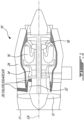
- FIG. 1 illustrates gas turbine engine 10 (referred hereinafter as "engine 10") of a type preferably provided for use in subsonic flight, generally comprising in serial flow communication, air inlet 11 for receiving ambient air, fan 12 through which the ambient air is propelled, a multistage compressor 14 for pressurizing the air, a combustor 16 in which the pressurized air is mixed with fuel and ignited to generate an annular stream of hot combustion gas(es), and turbine section 18 including one or more turbines for extracting energy from the combustion gas(es).
- Engine 10 may be of a type suitable for use in aircraft applications.
- engine 10 may be a turbofan (as illustrated), a turboshaft or a turboprop type of aircraft engine.
- Engine 10 may include one or more composite guide vanes 120, 220, 320, 420, 520 (also referred generally herein in the singular as "vane 20") made using one or more methods described herein.
- Vane 20 may be of a type known as a "guide vane” or “stator vane” that is used to direct fluid flow toward a desired direction so as to be received onto downstream rotor blades at a desired orientation (angle) for example.
- vane 20 may be suitable for installation in core gas path 22 of engine 10.
- Compressor 14, combustor 16 and one or more turbines of turbine section 18 may be disposed serially along core gas path 22.
- vane 20 may be a (e.g., variable orientation) inlet guide vane or other type of vane disposed upstream of compressor 14. In some embodiments, vane 20 may be disposed between two rotor stages of compressor 14. Alternatively, vane 20 may be a bypass stator vane disposed in a bypass duct 24 of engine 10. In various embodiments, vane 20 may have a fixed orientation within engine 10 or may have a controllably variable orientation within engine 10.
- Engine 10 may have central axis CA corresponding to an axis of rotation of one or more spools of engine 10.
- Bypass duct 24 may extend generally annularly about central axis CA.
- Core gas path 22 may also extend generally annularly about central axis CA.
- Bypass duct 24 may be disposed radially outwardly of core gas path 22 relative to central axis CA.
- a plurality of vanes 20 may be angularly distributed about central axis CA in bypass duct 24 and/or in core gas path 22.
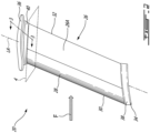
- FIG. 2 is a perspective view of an exemplary vane 20 of engine 10.
- Vane 20 may include body 26 for interacting with a flow of fluid (e.g., air) in engine 10.
- Body 26 may be elongated so as to extend across core gas path 22 or bypass duct 24.
- Body 26 may have longitudinal axis LA extending lengthwise along body 26.
- Longitudinal axis LA may be perpendicular or non-perpendicular (e.g., oblique) to central axis CA.
- Longitudinal axis LA may be linear or curved.
- Longitudinal axis LA may extend through each transverse section of body 26 and may intersect central axis CA.
- Body 26 may have an airfoil-shaped cross-sectional profile taken transversely to longitudinal axis LA such as in reference plane 4 for example.
- Plane 4 may be orthogonal to longitudinal axis LA at an intersection of plane 4 with longitudinal axis LA.
- Body 26 may be made from one or more fibrous (i.e., fiber-reinforced) composite materials.
- vane 20 may include optional metallic sheath 28 covering (e.g., a forward) part of body 26.
- metallic sheath 28 may define leading edge 30 of vane 20.
- Metallic sheath 28 may provide resistance against erosion, abrasion and impact from foreign objects that may enter engine 10.
- metallic sheath 28 may be applied to body 26 by way of plating.
- Leading edge 30 and trailing edge 32 of vane 20 are illustrated in relation to a general direction F of the flow of fluid interacting with vane 20.
- Vane 20 may include elements of the vanes described in US Patent No. 11,352,891 (Title: METHOD FOR MANUFACTURING A COMPOSITE GUIDE VANE HAVING A METALLIC LEADING EDGE).
- Vane 20 may have foot 34 and head 36 attached to respective opposite ends of vane 20. Foot 34 and head 36 may have similar or different configurations. In some embodiments, vane 20 may have either foot 34 or head 36 for attachment of vane 20 only from one end of vane 20. In relation to central axis CA of engine 10, foot 34 may be disposed at a radially inner end of body 26 of vane 20. Head 36 may be disposed at a radially outer end of body 26 of vane 20.
- Foot 34 may facilitate the attachment of vane 20 to a radially inner support structure (e.g., inner ring, shroud, engine casing, low pressure compressor housing) and head 36 may facilitated the attachment of vane 20 to a radially outer support structure (e.g., outer ring, shroud, engine casing).
- Vane 20 may also include radially inner platform 38 and radially outer platform 40 for interacting with the flow of fluid. Platforms 38, 40 may define flow-interacting surfaces between vanes 20 that are adjacent in the angular/circumferential direction about central axis CA.
- Foot 34 and head 36 intersecting body 26 may define a generally T-shape, L-shape or any shape suitable to facilitate installation and attachment of vane 20 within engine 10.
- FIGS. 3A-3E each are schematic longitudinal cross-section views of exemplary embodiments of vane 20 taken along line 3-3 in FIG. 2 .
- Like elements are identified using like reference numerals that have been successively incremented by 100 in each of FIGS. 3A-3E .
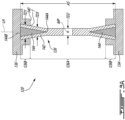
- FIG. 3A illustrates a longitudinal cross-section of vane 120 which may include body 126 having longitudinal axis LA. Vane 120 is shown as having a non-specific length along longitudinal axis LA.
- Body 126 may include (e.g., composite) laminate 142 and (e.g., composite) insert 144 disposed inside (e.g., sandwiched between layers of) laminate 142.
- Laminate 142 may be made of an assembly of layers of a fibrous composite material such as fiber-reinforced composite sheets (e.g., fiber-reinforced unidirectional tape and/or fabric) joined together.
- Laminate 142 may define mid portion 126A of body 126 for interacting with the fluid, and end portion(s) 126B of body 126 disposed axially of mid portion 126A. In some embodiments, mid portion 126A may be disposed axially between two end portions 126B.
- Vane 120 may include one or more inserts 144 made of another fibrous composite material.
- Insert 144 may extend axially (e.g., along longitudinal axis A) from a first axial location in end portion 126B of body 126 to a second axial location in mid portion 126A of body 126.
- insert 144 may extend axially from end portion 126B of body 126 into mid portion 126A of body 126 and terminate in mid portion 126A of body 126.
- insert 144 may have a generally tapered shape toward the opposite axial end of vane 120.
- insert 144 may be wedge-shaped and may include base 144B disposed in end portion 126B, and apex 144A axially opposite of base 144B and disposed in mid portion 126A of body 126.
- Vane 120 may also include head 136 enveloping end portion 126B of body 126. In some embodiments, head 136 may be overmolded onto end portion 126B of body 126.
- the present description mainly refers to an upper portion of vane 120 including head 36 for conciseness but it is understood that the present description may also or instead apply to a lower portion of vane 120 including foot 134 enveloping (e.g., being overmolded onto) end portion 126B of body 126.
- the lower portion of vane 120 may optionally have a similar or substantially identical construction as the upper portion of vane 120 described herein.
- the upper portion of vane 120 and the lower portion of vane 120 may have different constructions.
- Insert 144 may extend only partially along axial span AS of body 126. In other words, insert 144 may not extend along the entire axial span AS of body 126. For example, insert 144 may terminate in mid portion 126A of body 126. For example, an axial span of insert 144 (i.e., the axial distance between base 144B and apex 144A) may be less then half of axial span AS of body 126. For example, insert 144 may not extend past axial midpoint MP of mid portion 126A of body 126.
- Insert 144 may be used to reinforce (e.g., bulk-up, thicken) a region of body 126 that is enveloped by head 136 and/or that is adjacent to head 136.
- a thicker region of body 126 interfacing with head 136 may serve to enhance the structural performance and optionally permit the use of a relatively sharp transition T between body 126 and outer platform 140 of head 136 instead of a rounded transition (e.g., fillet). It may be desirable to have such relatively sharp transition T for structural reasons and/or to facilitate manufacturing. Thickening of the applicable region(s) of body 126 may serve to reduce stresses in body 126 when vane 120 is subjected to bending loads for example.
- tapered insert 144 may permit the increase in thickness of body 126 to be substantially gradual along longitudinal axis LA.
- body 126 may also be tapered so that an axially transverse dimension (i.e., transverse to longitudinal axis LA) of body 126 may diminish gradually from end portion 126B toward axial midpoint MP of mid portion 126A of body 126.
- the shape and configuration of insert 144 (and consequently of body 126) may also provide mechanical interlocking between body 126 and head 136 so as to enhance the retention of body 126 within head 136. For example, having an end portion 126B of body 126 shaped to provide a larger transverse dimension radially outwardly of a smaller transverse dimension may provide anchoring of end portion 126B within head 136.
- body 126 may have a transverse dimension (e.g., width) that is non-uniform along longitudinal axis LA at least partially due to the presence of insert 144 inside of laminate 142.
- body 126 may have first transverse dimension TD1 within end portion 126B of body 126, second transverse dimension TD2 at axial midpoint MP of mid portion 126A of body 126, and third transverse dimension TD3 at an axial location between axial midpoint MP of mid portion 126A and end portion 126B of body 126.
- Third transverse dimension TD3 may be axially closer to end portion 126B than to axial mid point MP of mid portion 126A.
- Third transverse dimension TD3 may be greater than second transverse dimension TD2.
- First transverse dimension TD1 may be greater than both second transverse dimension TD2 and third transverse dimension TD3.
- First transverse dimension TD1 and third transverse dimension TD3 may be taken at respective axial locations that axially overlap insert 144.
- Second transverse dimension TD2 may be taken at an axial location that does not axially overlap insert 144.
- transverse dimensions TD1, TD2 and TD3 may correspond maximum thicknesses of airfoil-shaped cross-sectional profiles of body 126 taken at different axial locations along longitudinal axis LA.
- the airfoil-shaped cross-sectional profile of mid portion 126A of body 126 may have a maximum thickness that is axially non-uniform along longitudinal axis LA.
- mid portion 126A of body 126 may have a first airfoil-shaped cross-sectional profile having a first maximum thickness (e.g., third transverse dimension TD3) and being at a first axial distance from end portion 126B of body 126.
- Mid portion 126A may have a second airfoil-shaped cross-sectional profile having a second maximum thickness (e.g., second transverse dimension TD2) that is smaller than the first maximum thickness.
- the second airfoil-shaped cross-sectional profile may be at a second axial distance from end portion 126B of body 126 greater than the first axial distance.
- FIGS. 3B-3E each show an upper portion of vane 20 including head 36 but it is understood that the descriptions and illustrations of the upper portion of vane 20 could alternatively or additionally apply to the lower portion of vane 20 including foot 34.
- FIG. 3B illustrates a longitudinal cross-section of an upper portion of vane 220 which may include body 226 having longitudinal axis LA. Vane 220 may include elements of other vanes disclosed herein.
- Body 226 may include (e.g., composite) laminate 242 and (e.g., composite) insert 244 disposed inside (e.g., sandwiched between layers of) laminate 242.
- Laminate 242 may define mid portion 226A of body 226 for interacting with the fluid, and end portion 226B of body 226 disposed axially of mid portion 226A.
- insert 244 may have one or more planar sides and/or one or more nonplanar (curved) sides. The shape and size of insert 244 may be selected based on aerodynamic and/or structural considerations.
- FIG. 3B Interfaces between components of vane 220 are illustrated in FIG. 3B using broken lines.
- the components of vane 220 may be joined together at the interfaces using any suitable means.
- the components of vane 220 may be fused together where the components are combined/united into a whole by melting the elements together at the interfaces shown in broken lines.
- the fused interfaces illustrated in FIG. 3B may also apply to other vane constructions disclosed herein.
- the elements of vane 220 may be made from materials that are compatible to permit fusing at direct contact interfaces between the components with the application of heat.
- insert 244 and laminate 242 may include compatible (e.g., matrix) materials that permit the fusing of insert 244 together with laminate 242 during the consolidation of body 226 for example.
- head 236 may include a (e.g., matrix) material that is compatible with a (e.g., matrix) material of insert 244 and/or with a (e.g., matrix) material of laminate 242 so that head 236 may be fused with base 244B of insert 244 and/or with outer surface(s) of laminate 242 during overmolding of head 236 onto end portion 226B for example.
- compatible materials that permit fusing between components may be thermoplastics that become pliable or moldable at a certain elevated temperature and solidify upon cooling.
- one or more components of vane 220 may be made from a thermosetting polymer that is obtained by irreversible hardening (curing).
- FIG. 3C illustrates a longitudinal cross-section of an upper portion of vane 320 which may include body 326 having longitudinal axis LA.
- Vane 320 may include elements of other vanes disclosed herein.
- Body 326 may include (e.g., composite) laminate 342 and (e.g., composite) insert 344 disposed inside (e.g., sandwiched between layers of) laminate 342.
- Laminate 342 may define mid portion 326A of body 326 for interacting with the fluid, and end portion 326B of body 326 disposed axially of mid portion 326A and enveloped by head 336.
- FIG. 3D illustrates a longitudinal cross-section of an upper portion of vane 420 which may include body 426 having longitudinal axis LA.
- Vane 420 may include elements of other vanes disclosed herein.
- Body 426 may include (e.g., composite) laminate 442 and (e.g., composite) insert 444 disposed inside (e.g., sandwiched between layers of) laminate 442.
- Laminate 442 may define mid portion 426A of body 426 for interacting with the fluid, and end portion 426B of body 426 disposed axially of mid portion 426A and enveloped by head 436.
- insert 444 may have a substantially uniform transverse dimension along longitudinal axis LA.
- insert 444 may have fourth transverse dimension TD4 in end portion 426B of body 426 and fifth transverse dimension TD5 in mid portion 426A of body 426.
- Fourth transverse dimension TD4 may be substantially the same as (equal to) fifth axially transverse dimension TD5.
- insert 544 may have one or more recesses 546, one or more protrusions 548 and/or other surface features to promote anchoring between laminate 542 and insert 544.
- Recess(es) 546 and/or protrusion(s) 548 may be disposed axially between base 544B and apex 544A of insert 544.
- Fibrous composite material of laminate 542 may be received into recess(es) 546.
- Protrusion(s) 548 may extend at least partially transversely (to longitudinal axis LA) into the fibrous composite material of laminate 542.
- FIG. 4 is an exemplary schematic transverse cross-section of vane 20 of FIG. 2 intersecting plane 4 in FIG. 2 .
- Plane 4 is disposed in mid portion 26A (shown in FIG. 2 ) of body 26 at a location intersecting insert 44 integrated into (e.g., composite) laminate 42.
- vane 20 may have an airfoil-shaped cross-sectional profile.
- the airfoil-shaped cross-sectional profile may be symmetric or non-symmetric.
- the airfoil-shaped cross-sectional profile may have chord C extending from leading edge 30 to trailing edge 32, and having a chord length.
- Transverse dimension TD of body 26 at a location intersecting plane 4 may correspond to a maximum thickness of airfoil-shaped cross-sectional profile measured perpendicularly to chord C.
- FIG. 5 a flow diagram of an exemplary method 100 of manufacturing any one of vane(s) 20, 120, 220, 320, 420, 520 or other composite guide vane(s).
- Method 100 may include other actions disclosed herein and/or may include elements of any of vane(s) 20, 120, 220, 320, 420, 520. Aspects of method 100 are described below in reference to FIGS. 6-10 and in reference to vane 120 being used as an example.
- method 100 may include:
- FIG. 6 is a schematic cross-sectional representation of insert 144 of vane 120 together with mold portions 54A, 54B for forming insert 144 using injection molding using molding material. Mold portions 54A, 54B are shown as being brought together to form insert 144 while molding material in a molten state is being injected inside the cavity defined by mold portions 54A, 54B and subsequently cooled inside of the cavity. Mold portions 54A, 54B may also be movable away from each other to release insert 144 from mold portions 54A, 54B after forming.
- insert 144 may be made by injection molding using short fibers embedded in a thermoplastic or thermosetting matrix material. Such short fibers may have lengths of a few millimeters or less. For example, such short fibers may have lengths of about 5 mm or less. In some embodiments, such short fibers may have lengths of about 2 mm or less. In some embodiments, such short fibers may have lengths of about 1 mm or less. In some embodiments, such short fibers may have lengths of between 1 mm and 5 mm. In some embodiments, insert 144 may be made by injection molding using a thermosetting or thermoplastic material (e.g., neat resin) that is devoid of any fiber reinforcement.
- a thermosetting or thermoplastic material e.g., neat resin
- insert 144 may be formed using another suitable process.
- the fibers of insert 144 may be continuous or discontinuous.
- the orientation of the fibers of insert 144 may be controlled or random in various embodiments.
- Insert 144 may include long, medium-length and/or short fibers.
- insert 144 may be formed from a layup of fiber-reinforced composite sheets (i.e., laminate stacking) combined with preforming or consolidation and/or compression molding.
- insert 144 may be formed using additive polymer manufacturing.
- insert 144 may machined from a block of fiber-reinforced composite material.
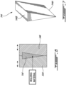
- FIG. 7 is a perspective view of insert 144 released from mold portions 54A, 54B of FIG. 6 .
- insert 144 may wedge-shaped (e.g., V-shaped, triangular-shaped wedge) as shown in FIG. 7 .
- FIG. 8 is a partial schematic cross-sectional representation of an exemplary layup 150 together with mold portions 56A, 56B for consolidating an exemplary upper portion of body 126 of vane 120 from layup 150 after forming insert 144.
- Layup 150 may include fiber-reinforced composite sheets 152 (i.e., layers of fibrous composite material) and insert 144 disposed between fiber-reinforced composite sheets 152.
- layup 150 may include insert 144 inserted (i.e., sandwiched) between two fiber-reinforced composite sheets 152.
- layup 150 may include insert 144 integrated in a stack of multiple (e.g., more than two) fiber-reinforced composite sheets 152.
- Layup 150 may be consolidated (e.g., at least partially densified) into a single unified body 126 using heat and pressure using a press defined by mold portions 56A, 56B for stamping/compression molding layup 150 to its desired shape.
- Sheets 152 may be a suitable continuous fiber reinforced thermoplastic (CFRT) composite.
- each sheet 152 may be a layer of continuous, substantially parallel and non-interlaced fibers pre-impregnated with a thermoplastic or thermosetting resin.
- each sheet 152 may be of a type known as "unidirectional tape” or "UD tape” where a single-layered, fiber-reinforced (e.g., thermoplastic) composite sheet in which long continuous fibers are unrolled, laid and impregnated with a (e.g., thermoplastic) resin.
- the UD tape may be pre-impregnated with resin.
- each sheet 152 may be a woven tissue/fabric cloth that is pre-impregnated with resin.
- sheets 152 may each have a thickness of about 0.005 inch (0.13 mm) or about 0.010 inch (0.25 mm).
- Sheets 152 may be cut automatically on a standard ply cutting table or formed using automated tape laying (ATL) equipment. Sheets 152 may be stacked manually or robotically in mold portions 56A, 56B. Sheets 152 may be pre-consolidated in a press or tack welded together before placing between mold portions 56A, 56B. Sheets 152 may be cut and stacked based on the desired final shape of body 126 after forming (e.g., stamping, compression molding) using mold portions 56A, 56B.
- ATL automated tape laying
- the orientation of respective sheets 152 in layup 150 may be selected to tailor the mechanical properties of body 126 in desired loading directions.
- sheets 152 in layup 150 may have different orientations (stacking angles).
- the use of sheets 152 with continuous unidirectional fibers and stacking angles may provide control over the final mechanical properties of body 126.
- at least some sheets 152 and hence some of the continuous unidirectional fibers may extend continuously along substantially an entire axial span AS (shown in FIG. 3A ) of body 126.
- at least some of the long fibers from sheets 152 may extend continuously from one end portion 126B, through mid portion 126A and to the other opposite end portion 126B.
- the materials of sheets 152 (for forming laminate 142), of insert 144 and optionally of head 136 and/or foot 134 may be compatible with each other so that during heating, consolidation and overmolding, a fused joint may be formed between the components of vane 120.
- Insert 144, laminate 142, and optionally head 136 and/or foot 134 may include long and/or short fibers embedded in a suitable (e.g., polymeric) matrix material.
- the fibers may, for example, be made from glass and/or carbon.
- Matrix materials may include thermoplastic resins and/or thermosetting resins.
- suitable matrix materials for insert 144, laminate 142, foot 34 and/or head 36 may include polyether ether ketone (PEEK), such as product numbers 450CA30 or 90HMF40 by VICTREX TM , polyamide, epoxy, polyurethane, phenolic and amino resins, and bismaleimides (BMI) for example.
- PEEK polyether ether ketone
- sheets 152 may include unidirectional carbon fiber reinforced thermoplastic tape.
- sheets 152 may include polyaryletherketone (PAEK) impregnated UD tape.
- insert 144, foot 34 and/or head 36 may be made from a relatively high performance thermoplastic material such as product number 90HMF40 which includes 40% carbon fiber reinforced polyetheretherketone (PEEK) and semi crystalline in the form of granules suitable for injection molding.
- a relatively high performance thermoplastic material such as product number 90HMF40 which includes 40% carbon fiber reinforced polyetheretherketone (PEEK) and semi crystalline in the form of granules suitable for injection molding.
- the layers of fibers (i.e., sheets 152) in layup 150 may include unidirectional tape of first fibers impregnated with a first matrix material.
- Insert 144 may includes a second matrix material. Consolidating layup 150 into body 126 using heat and pressure may include fusing the first matrix material of sheets 152 with the second matrix material of insert 144.
- the fibers in sheets 152 may include continuous fibers extending continuously along an entire axial span AS of body 126.
- Sheets 152 may include continuous, substantially parallel and non-interlaced fibers impregnated with a thermoplastic resin.
- Insert 144 may include (e.g., randomly oriented) fibers that are shorter than the continuous fibers of sheets 152.
- sheets 152 may include a first thermoplastic matrix material.
- Insert 144 may include a second thermoplastic matrix material.
- Consolidating layup 150 into body 126 may include fusing sheets 152 with the insert 144.
- FIG. 9 is a longitudinal cross-section view of an upper portion of stamped body 126 of vane 120 released from mold portions 56A, 56B of FIG. 8 .
- Body 126 may have longitudinal axis LA and may include mid portion 126A for interacting with the fluid and end portion 126B disposed axially of mid portion 126A.
- Insert 144 may extend axially from a first location in end portion 126B to a second location in mid portion 126A.
- FIG. 10 is a schematic representation of a side view of vane 120 together mold portions 58A, 58B for injection overmolding head 136 and mold portions 58C, 58D for injection overmolding foot 134 on body 126.
- Head 136 and/or foot 134 may be overmolded onto body 126 after the forming of body 126. Inserts 144 are shown in broken lines.
- Head 136 and foot 134 are shown as being transparent for clarity and for illustrating the components enveloped by head 136 and foot 134 by way of overmolding.
- Head 136 and foot 134 may be overmolded using suitable overmolding material.
- the overmolding material may include a thermoplastic or thermosetting resin containing relatively short (and optionally randomly oriented) reinforcement fibers as described above. The fibers in the overmolding material may be shorter than the fibers in laminate 142 (shown in FIG. 9 ).
- the overmolding material may include a thermoplastic or thermosetting resin that is devoid of reinforcement fibers.
- the thermoplastic or thermosetting resin selected for the overmolding material may be substantially identical or chemically compatible with one or more resins used in body 126.
- the overmolding material of head 136 and/or foot 134 may be fibrous composite material including a matrix material.
- Overmolding head 136 and/or foot 134 of vane 120 onto end portion(s) 126B of body 126 may include: fusing the matrix material of head 136 and/or foot 134 with the matrix material of laminate 142; and/or fusing the matrix material of head 136 and/or foot 134 with the matrix material of insert 144.
Landscapes
- Engineering & Computer Science (AREA)
- Mechanical Engineering (AREA)
- General Engineering & Computer Science (AREA)
- Chemical & Material Sciences (AREA)
- Materials Engineering (AREA)
- Composite Materials (AREA)
- Structures Of Non-Positive Displacement Pumps (AREA)
- Turbine Rotor Nozzle Sealing (AREA)
Abstract
Composite guide vanes (120) for gas turbine engines are described together with methods of manufacturing such composite guide vanes (120). A composite guide vane (120) comprises a body (126) having a longitudinal axis (LA) and including a composite laminate (142) made of an assembly of layers of a first fibrous composite material. The composite laminate (142) defines a mid portion (126A) of the body (126) for interacting with a fluid and an end portion (1268) of the body (126) disposed axially of the mid portion (126A) of the body (126). A composite insert (144) is disposed inside the composite laminate (142) and made of a second fibrous composite material. The composite insert (144) extends axially from the end portion (1268) of the body (126) to a second location in the mid portion (126A) of the body (126). A head (136) or foot (134) of the composite guide vane (120) envelops the end portion (1268) of the body (126).
Description
- The disclosure relates generally to gas turbine engines, and more particularly to composite guide vanes.
- Guide vanes are typically arranged in rows and serve to guide a gas stream passing through a gas turbine engine toward a desired orientation. Guide vanes are generally made of metal, but it is becoming desirable to make them out of composite materials to reduce their weight. Methods of fabricating guide vanes out of composite materials can be complex, require expensive tooling and be time consuming. Improvement is desirable.
- In one aspect, the disclosure describes a composite guide vane for a gas turbine engine. The composite guide vane comprises: a body having a longitudinal axis, the body including: a composite laminate made of an assembly of layers of a first fibrous composite material, the composite laminate defining a mid portion of the body for interacting with a fluid and an end portion of the body disposed axially of the mid portion of the body; and a composite insert disposed inside the composite laminate and made of a second fibrous composite material, the composite insert extending axially from the end portion of the body into the mid portion of the body and terminating in the mid portion of the body; and a head or foot overmolded onto the end portion of the body.
- In another aspect, the disclosure describes a gas turbine engine comprising: an air inlet for receiving air; a compressor for pressurizing the air; a combustor in which the air is received from the compressor, mixed with fuel and ignited for generating a stream of combustion gas; a turbine for extracting energy from the combustion gas; and a composite guide vane for interacting with the air, the composite guide vane including: a body having a longitudinal axis, the body including: a composite laminate made of an assembly of layers of a fibrous composite material, the composite laminate defining a mid portion of the body for interacting with a fluid and an end portion of the body disposed axially of the mid portion; and an insert sandwiched between two of the layers of the composite laminate and fused with the composite laminate, the insert extending axially from the end portion into the mid portion and terminating in the mid portion of the body; and a head or foot enveloping the end portion of the body.
- In a further aspect, the disclosure describes a method of manufacturing a composite guide vane of a gas turbine engine. The method comprises: receiving a layup including fiber-reinforced composite sheets and a composite insert disposed between the fiber-reinforced composite sheets; consolidating the layup into a unified body using heat and pressure, the body having a longitudinal axis and including a mid portion for interacting with a fluid and an end portion disposed axially of the mid portion, the composite insert extending axially from a first location in the end portion to a second location in the mid portion; and overmolding a head or foot of the composite guide vane onto the end portion of the body.
- Features of embodiments are set forth in the dependent claims.
- Further details of these and other aspects of the subject matter of this application will be apparent from the detailed description included below and the drawings.
- Reference is now made to the accompanying drawings, in which:
-
FIG. 1 shows a schematic axial cross-section view of a turbofan gas turbine engine including one or more composite guide vanes as described herein; -
FIG. 2 is a perspective view of an exemplary composite guide vane of the engine ofFIG. 1 ; -
FIG. 3A is a schematic longitudinal cross-section view of an exemplary embodiment of the composite guide vane ofFIG. 2 taken along line 3-3 inFIG. 2 ; -
FIG. 3B is a schematic longitudinal cross-section view of an upper portion of another exemplary embodiment of the composite guide vane ofFIG. 2 taken along line 3-3 inFIG. 2 ; -
FIG. 3C is a schematic longitudinal cross-section view of an upper portion of another exemplary embodiment of the composite guide vane ofFIG. 2 taken along line 3-3 inFIG. 2 ; -
FIG. 3D is a schematic longitudinal cross-section view of an upper portion of another exemplary embodiment of the composite guide vane ofFIG. 2 taken along line 3-3 inFIG. 2 ; -
FIG. 3E is a schematic longitudinal cross-section view of an upper portion of another exemplary embodiment of the composite guide vane ofFIG. 2 taken along line 3-3 inFIG. 2 ; -
FIG. 4 is an exemplary schematic transverse cross-section of the composite guide vane ofFIG. 2 intersectingplane 4 inFIG. 2 ; -
FIG. 5 a flowchart of an exemplary method of manufacturing a composite guide vane; -
FIG. 6 is a schematic cross-sectional representation of an exemplary composite insert of the composite guide vane ofFIG. 2 together with mold portions for forming the composite insert; -
FIG. 7 is a perspective view of the composite insert ofFIG. 6 ; -
FIG. 8 is a partial schematic cross-sectional representation of an exemplary layup together with mold portions for consolidating an exemplary upper portion of the body of the composite guide vane; -
FIG. 9 is a longitudinal cross-section view of the upper portion of the body of the composite guide vane; and -
FIG. 10 is a schematic representation of an exemplary composite guide vane together with mold portions for overmolding a head and a foot on the body of the composite guide vane. - The following disclosure describes constructions of composite guide vanes for gas turbine engines and methods of manufacturing such composite guide vanes. In some embodiments, the methods described herein may facilitate the manufacturing of composite guide vanes having improved durability. For example, in some embodiments, the composite guide vanes disclosed herein may include an insert integrated in a body of the composite guide vane to promote reduced stresses in the composite guide vane due to aerodynamic pressure loading and foreign object impact during use. In some embodiments, the composite guide vanes disclosed herein may also promote mechanical retention of the body with a head and/or foot of the composite guide vane.
- The term "substantially" as used herein may be applied to modify any quantitative representation which could permissibly vary without resulting in a change in the basic function to which it is related. For example, component dimensions that are referred herein as "substantially the same" may permissibly differ by amounts tied to dimensional tolerances associated with the manufacturing processes used.
- Aspects of various embodiments are described through reference to the drawings.
-
FIG. 1 illustrates gas turbine engine 10 (referred hereinafter as "engine 10") of a type preferably provided for use in subsonic flight, generally comprising in serial flow communication,air inlet 11 for receiving ambient air,fan 12 through which the ambient air is propelled, amultistage compressor 14 for pressurizing the air, acombustor 16 in which the pressurized air is mixed with fuel and ignited to generate an annular stream of hot combustion gas(es), andturbine section 18 including one or more turbines for extracting energy from the combustion gas(es).Engine 10 may be of a type suitable for use in aircraft applications. For example,engine 10 may be a turbofan (as illustrated), a turboshaft or a turboprop type of aircraft engine. -
Engine 10 may include one or morecomposite guide vanes vane 20") made using one or more methods described herein. Vane 20 may be of a type known as a "guide vane" or "stator vane" that is used to direct fluid flow toward a desired direction so as to be received onto downstream rotor blades at a desired orientation (angle) for example. In some embodiments,vane 20 may be suitable for installation incore gas path 22 ofengine 10.Compressor 14,combustor 16 and one or more turbines ofturbine section 18 may be disposed serially alongcore gas path 22. In some embodiments,vane 20 may be a (e.g., variable orientation) inlet guide vane or other type of vane disposed upstream ofcompressor 14. In some embodiments,vane 20 may be disposed between two rotor stages ofcompressor 14. Alternatively,vane 20 may be a bypass stator vane disposed in abypass duct 24 ofengine 10. In various embodiments,vane 20 may have a fixed orientation withinengine 10 or may have a controllably variable orientation withinengine 10. -
Engine 10 may have central axis CA corresponding to an axis of rotation of one or more spools ofengine 10.Bypass duct 24 may extend generally annularly about central axis CA.Core gas path 22 may also extend generally annularly about central axis CA.Bypass duct 24 may be disposed radially outwardly ofcore gas path 22 relative to central axis CA. In some embodiments ofengine 10, a plurality ofvanes 20 may be angularly distributed about central axis CA inbypass duct 24 and/or incore gas path 22. -
FIG. 2 is a perspective view of anexemplary vane 20 ofengine 10. Vane 20 may includebody 26 for interacting with a flow of fluid (e.g., air) inengine 10.Body 26 may be elongated so as to extend acrosscore gas path 22 orbypass duct 24.Body 26 may have longitudinal axis LA extending lengthwise alongbody 26. Longitudinal axis LA may be perpendicular or non-perpendicular (e.g., oblique) to central axis CA. Longitudinal axis LA may be linear or curved. Longitudinal axis LA may extend through each transverse section ofbody 26 and may intersect central axis CA.Body 26 may have an airfoil-shaped cross-sectional profile taken transversely to longitudinal axis LA such as inreference plane 4 for example.Plane 4 may be orthogonal to longitudinal axis LA at an intersection ofplane 4 with longitudinal axis LA. -
Body 26 may be made from one or more fibrous (i.e., fiber-reinforced) composite materials. In some embodiments,vane 20 may include optionalmetallic sheath 28 covering (e.g., a forward) part ofbody 26. For example,metallic sheath 28 may define leadingedge 30 ofvane 20.Metallic sheath 28 may provide resistance against erosion, abrasion and impact from foreign objects that may enterengine 10. In some embodiments,metallic sheath 28 may be applied tobody 26 by way of plating. Leadingedge 30 and trailingedge 32 ofvane 20 are illustrated in relation to a general direction F of the flow of fluid interacting withvane 20.Vane 20 may include elements of the vanes described inUS Patent No. 11,352,891 -
Vane 20 may havefoot 34 andhead 36 attached to respective opposite ends ofvane 20.Foot 34 andhead 36 may have similar or different configurations. In some embodiments,vane 20 may have eitherfoot 34 orhead 36 for attachment ofvane 20 only from one end ofvane 20. In relation to central axis CA ofengine 10,foot 34 may be disposed at a radially inner end ofbody 26 ofvane 20.Head 36 may be disposed at a radially outer end ofbody 26 ofvane 20.Foot 34 may facilitate the attachment ofvane 20 to a radially inner support structure (e.g., inner ring, shroud, engine casing, low pressure compressor housing) andhead 36 may facilitated the attachment ofvane 20 to a radially outer support structure (e.g., outer ring, shroud, engine casing).Vane 20 may also include radiallyinner platform 38 and radiallyouter platform 40 for interacting with the flow of fluid.Platforms vanes 20 that are adjacent in the angular/circumferential direction about central axis CA.Foot 34 andhead 36 intersectingbody 26 may define a generally T-shape, L-shape or any shape suitable to facilitate installation and attachment ofvane 20 withinengine 10. -
FIGS. 3A-3E each are schematic longitudinal cross-section views of exemplary embodiments ofvane 20 taken along line 3-3 inFIG. 2 . Like elements are identified using like reference numerals that have been successively incremented by 100 in each ofFIGS. 3A-3E . -
FIG. 3A illustrates a longitudinal cross-section ofvane 120 which may includebody 126 having longitudinal axis LA.Vane 120 is shown as having a non-specific length along longitudinal axis LA.Body 126 may include (e.g., composite)laminate 142 and (e.g., composite) insert 144 disposed inside (e.g., sandwiched between layers of)laminate 142.Laminate 142 may be made of an assembly of layers of a fibrous composite material such as fiber-reinforced composite sheets (e.g., fiber-reinforced unidirectional tape and/or fabric) joined together.Laminate 142 may definemid portion 126A ofbody 126 for interacting with the fluid, and end portion(s) 126B ofbody 126 disposed axially ofmid portion 126A. In some embodiments,mid portion 126A may be disposed axially between twoend portions 126B. -
Vane 120 may include one ormore inserts 144 made of another fibrous composite material.Insert 144 may extend axially (e.g., along longitudinal axis A) from a first axial location inend portion 126B ofbody 126 to a second axial location inmid portion 126A ofbody 126. For example, insert 144 may extend axially fromend portion 126B ofbody 126 intomid portion 126A ofbody 126 and terminate inmid portion 126A ofbody 126. In some embodiments, insert 144 may have a generally tapered shape toward the opposite axial end ofvane 120. For example, insert 144 may be wedge-shaped and may includebase 144B disposed inend portion 126B, and apex 144A axially opposite ofbase 144B and disposed inmid portion 126A ofbody 126.Vane 120 may also includehead 136 envelopingend portion 126B ofbody 126. In some embodiments,head 136 may be overmolded ontoend portion 126B ofbody 126. - The present description mainly refers to an upper portion of
vane 120 includinghead 36 for conciseness but it is understood that the present description may also or instead apply to a lower portion ofvane 120 includingfoot 134 enveloping (e.g., being overmolded onto)end portion 126B ofbody 126. In some embodiments, the lower portion ofvane 120 may optionally have a similar or substantially identical construction as the upper portion ofvane 120 described herein. Alternatively, in some embodiments, the upper portion ofvane 120 and the lower portion ofvane 120 may have different constructions. -
Insert 144 may extend only partially along axial span AS ofbody 126. In other words, insert 144 may not extend along the entire axial span AS ofbody 126. For example, insert 144 may terminate inmid portion 126A ofbody 126. For example, an axial span of insert 144 (i.e., the axial distance betweenbase 144B and apex 144A) may be less then half of axial span AS ofbody 126. For example, insert 144 may not extend past axial midpoint MP ofmid portion 126A ofbody 126. -
Insert 144 may be used to reinforce (e.g., bulk-up, thicken) a region ofbody 126 that is enveloped byhead 136 and/or that is adjacent to head 136. In some embodiments, a thicker region ofbody 126 interfacing withhead 136 may serve to enhance the structural performance and optionally permit the use of a relatively sharp transition T betweenbody 126 andouter platform 140 ofhead 136 instead of a rounded transition (e.g., fillet). It may be desirable to have such relatively sharp transition T for structural reasons and/or to facilitate manufacturing. Thickening of the applicable region(s) ofbody 126 may serve to reduce stresses inbody 126 whenvane 120 is subjected to bending loads for example. - The use of tapered
insert 144 may permit the increase in thickness ofbody 126 to be substantially gradual along longitudinal axis LA. In other words,body 126 may also be tapered so that an axially transverse dimension (i.e., transverse to longitudinal axis LA) ofbody 126 may diminish gradually fromend portion 126B toward axial midpoint MP ofmid portion 126A ofbody 126. The shape and configuration of insert 144 (and consequently of body 126) may also provide mechanical interlocking betweenbody 126 andhead 136 so as to enhance the retention ofbody 126 withinhead 136. For example, having anend portion 126B ofbody 126 shaped to provide a larger transverse dimension radially outwardly of a smaller transverse dimension may provide anchoring ofend portion 126B withinhead 136. - In various embodiments,
body 126 may have a transverse dimension (e.g., width) that is non-uniform along longitudinal axis LA at least partially due to the presence ofinsert 144 inside oflaminate 142. For example,body 126 may have first transverse dimension TD1 withinend portion 126B ofbody 126, second transverse dimension TD2 at axial midpoint MP ofmid portion 126A ofbody 126, and third transverse dimension TD3 at an axial location between axial midpoint MP ofmid portion 126A andend portion 126B ofbody 126. Third transverse dimension TD3 may be axially closer to endportion 126B than to axial mid point MP ofmid portion 126A. Third transverse dimension TD3 may be greater than second transverse dimension TD2. First transverse dimension TD1 may be greater than both second transverse dimension TD2 and third transverse dimension TD3. First transverse dimension TD1 and third transverse dimension TD3 may be taken at respective axial locations that axially overlapinsert 144. Second transverse dimension TD2 may be taken at an axial location that does not axiallyoverlap insert 144. - In embodiments where
body 126 has an airfoil-shaped cross-sectional profile as shown inFIG. 4 for example, transverse dimensions TD1, TD2 and TD3 may correspond maximum thicknesses of airfoil-shaped cross-sectional profiles ofbody 126 taken at different axial locations along longitudinal axis LA. In some embodiments, the airfoil-shaped cross-sectional profile ofmid portion 126A ofbody 126 may have a maximum thickness that is axially non-uniform along longitudinal axis LA. For example,mid portion 126A ofbody 126 may have a first airfoil-shaped cross-sectional profile having a first maximum thickness (e.g., third transverse dimension TD3) and being at a first axial distance fromend portion 126B ofbody 126.Mid portion 126A may have a second airfoil-shaped cross-sectional profile having a second maximum thickness (e.g., second transverse dimension TD2) that is smaller than the first maximum thickness. The second airfoil-shaped cross-sectional profile may be at a second axial distance fromend portion 126B ofbody 126 greater than the first axial distance. -
FIGS. 3B-3E each show an upper portion ofvane 20 includinghead 36 but it is understood that the descriptions and illustrations of the upper portion ofvane 20 could alternatively or additionally apply to the lower portion ofvane 20 includingfoot 34. -
FIG. 3B illustrates a longitudinal cross-section of an upper portion ofvane 220 which may includebody 226 having longitudinal axis LA.Vane 220 may include elements of other vanes disclosed herein.Body 226 may include (e.g., composite)laminate 242 and (e.g., composite) insert 244 disposed inside (e.g., sandwiched between layers of)laminate 242.Laminate 242 may definemid portion 226A ofbody 226 for interacting with the fluid, andend portion 226B ofbody 226 disposed axially ofmid portion 226A. In some embodiments, insert 244 may have one or more planar sides and/or one or more nonplanar (curved) sides. The shape and size ofinsert 244 may be selected based on aerodynamic and/or structural considerations. - Interfaces between components of
vane 220 are illustrated inFIG. 3B using broken lines. The components ofvane 220 may be joined together at the interfaces using any suitable means. In some embodiments using compatible materials, the components ofvane 220 may be fused together where the components are combined/united into a whole by melting the elements together at the interfaces shown in broken lines. The fused interfaces illustrated inFIG. 3B may also apply to other vane constructions disclosed herein. For example, the elements ofvane 220 may be made from materials that are compatible to permit fusing at direct contact interfaces between the components with the application of heat. For example, in some embodiments, insert 244 andlaminate 242 may include compatible (e.g., matrix) materials that permit the fusing ofinsert 244 together withlaminate 242 during the consolidation ofbody 226 for example. Similarly,head 236 may include a (e.g., matrix) material that is compatible with a (e.g., matrix) material ofinsert 244 and/or with a (e.g., matrix) material oflaminate 242 so thathead 236 may be fused withbase 244B ofinsert 244 and/or with outer surface(s) oflaminate 242 during overmolding ofhead 236 ontoend portion 226B for example. - In some embodiments, compatible materials that permit fusing between components may be thermoplastics that become pliable or moldable at a certain elevated temperature and solidify upon cooling. However, in some embodiments, one or more components of
vane 220 may be made from a thermosetting polymer that is obtained by irreversible hardening (curing). -
FIG. 3C illustrates a longitudinal cross-section of an upper portion ofvane 320 which may includebody 326 having longitudinal axis LA.Vane 320 may include elements of other vanes disclosed herein.Body 326 may include (e.g., composite)laminate 342 and (e.g., composite) insert 344 disposed inside (e.g., sandwiched between layers of)laminate 342.Laminate 342 may definemid portion 326A ofbody 326 for interacting with the fluid, andend portion 326B ofbody 326 disposed axially ofmid portion 326A and enveloped byhead 336. In some embodiments, insert 344 may be a truncatedwedge having base 344B and a relatively blunt apex 344A (e.g., rounded or flat surface) instead of the relatively sharp apex 144A ofvane 120 shown inFIG. 3A . -
FIG. 3D illustrates a longitudinal cross-section of an upper portion ofvane 420 which may includebody 426 having longitudinal axis LA.Vane 420 may include elements of other vanes disclosed herein.Body 426 may include (e.g., composite)laminate 442 and (e.g., composite) insert 444 disposed inside (e.g., sandwiched between layers of)laminate 442.Laminate 442 may definemid portion 426A ofbody 426 for interacting with the fluid, andend portion 426B ofbody 426 disposed axially ofmid portion 426A and enveloped byhead 436. In some embodiments, insert 444 may have a substantially uniform transverse dimension along longitudinal axis LA. For example, insert 444 may have fourth transverse dimension TD4 inend portion 426B ofbody 426 and fifth transverse dimension TD5 inmid portion 426A ofbody 426. Fourth transverse dimension TD4 may be substantially the same as (equal to) fifth axially transverse dimension TD5. -
FIG. 3E illustrates a longitudinal cross-section of an upper portion ofvane 520 which may includebody 526 having longitudinal axis LA.Vane 520 may include elements of other vanes disclosed herein.Body 526 may include (e.g., composite)laminate 542 and (e.g., composite) insert 544 disposed inside (e.g., sandwiched between layers of)laminate 542.Laminate 542 may definemid portion 526A ofbody 526 for interacting with the fluid, andend portion 526B ofbody 526 disposed axially ofmid portion 526A and enveloped byhead 536. In some embodiments, insert 544 may have one ormore recesses 546, one ormore protrusions 548 and/or other surface features to promote anchoring betweenlaminate 542 and insert 544. Recess(es) 546 and/or protrusion(s) 548 may be disposed axially betweenbase 544B and apex 544A ofinsert 544. Fibrous composite material oflaminate 542 may be received into recess(es) 546. Protrusion(s) 548 may extend at least partially transversely (to longitudinal axis LA) into the fibrous composite material oflaminate 542. -
FIG. 4 is an exemplary schematic transverse cross-section ofvane 20 ofFIG. 2 intersecting plane 4 inFIG. 2 .Plane 4 is disposed inmid portion 26A (shown inFIG. 2 ) ofbody 26 at alocation intersecting insert 44 integrated into (e.g., composite)laminate 42. In some embodiments,vane 20 may have an airfoil-shaped cross-sectional profile. In various embodiments, the airfoil-shaped cross-sectional profile may be symmetric or non-symmetric. The airfoil-shaped cross-sectional profile may have chord C extending from leadingedge 30 to trailingedge 32, and having a chord length. Transverse dimension TD ofbody 26 at alocation intersecting plane 4 may correspond to a maximum thickness of airfoil-shaped cross-sectional profile measured perpendicularly to chord C. -
FIG. 5 a flow diagram of anexemplary method 100 of manufacturing any one of vane(s) 20, 120, 220, 320, 420, 520 or other composite guide vane(s).Method 100 may include other actions disclosed herein and/or may include elements of any of vane(s) 20, 120, 220, 320, 420, 520. Aspects ofmethod 100 are described below in reference toFIGS. 6-10 and in reference tovane 120 being used as an example. In various embodiments,method 100 may include: - receiving layup 150 (shown in
FIG. 8 ) including fiber-reinforced composite sheets 152 (shown inFIG. 8 ) and insert 144 disposed between fiber-reinforced composite sheets 152 (block 102); - consolidating
layup 150 into aunified body 126 using heat and pressure (block 104); and -
overmolding head 136 orfoot 134 ofvane 120 ontoend portion 126B of body 126 (block 106). -
FIG. 6 is a schematic cross-sectional representation ofinsert 144 ofvane 120 together withmold portions insert 144 using injection molding using molding material.Mold portions insert 144 while molding material in a molten state is being injected inside the cavity defined bymold portions Mold portions insert 144 frommold portions - In some embodiments, insert 144 may be made by injection molding using short fibers embedded in a thermoplastic or thermosetting matrix material. Such short fibers may have lengths of a few millimeters or less. For example, such short fibers may have lengths of about 5 mm or less. In some embodiments, such short fibers may have lengths of about 2 mm or less. In some embodiments, such short fibers may have lengths of about 1 mm or less. In some embodiments, such short fibers may have lengths of between 1 mm and 5 mm. In some embodiments, insert 144 may be made by injection molding using a thermosetting or thermoplastic material (e.g., neat resin) that is devoid of any fiber reinforcement.
- Alternatively, insert 144 may be formed using another suitable process. The fibers of
insert 144 may be continuous or discontinuous. The orientation of the fibers ofinsert 144 may be controlled or random in various embodiments.Insert 144 may include long, medium-length and/or short fibers. For example, insert 144 may be formed from a layup of fiber-reinforced composite sheets (i.e., laminate stacking) combined with preforming or consolidation and/or compression molding. For example, insert 144 may be formed using additive polymer manufacturing. For example, insert 144 may machined from a block of fiber-reinforced composite material. -
FIG. 7 is a perspective view ofinsert 144 released frommold portions FIG. 6 . In some embodiments, insert 144 may wedge-shaped (e.g., V-shaped, triangular-shaped wedge) as shown inFIG. 7 . -
FIG. 8 is a partial schematic cross-sectional representation of anexemplary layup 150 together withmold portions body 126 ofvane 120 fromlayup 150 after forminginsert 144.Layup 150 may include fiber-reinforced composite sheets 152 (i.e., layers of fibrous composite material) and insert 144 disposed between fiber-reinforcedcomposite sheets 152. In some embodiments,layup 150 may includeinsert 144 inserted (i.e., sandwiched) between two fiber-reinforcedcomposite sheets 152. In some embodiments,layup 150 may include insert 144 integrated in a stack of multiple (e.g., more than two) fiber-reinforcedcomposite sheets 152.Layup 150 may be consolidated (e.g., at least partially densified) into a singleunified body 126 using heat and pressure using a press defined bymold portions compression molding layup 150 to its desired shape. -
Sheets 152 may be a suitable continuous fiber reinforced thermoplastic (CFRT) composite. For example, eachsheet 152 may be a layer of continuous, substantially parallel and non-interlaced fibers pre-impregnated with a thermoplastic or thermosetting resin. In some embodiments, eachsheet 152 may be of a type known as "unidirectional tape" or "UD tape" where a single-layered, fiber-reinforced (e.g., thermoplastic) composite sheet in which long continuous fibers are unrolled, laid and impregnated with a (e.g., thermoplastic) resin. The UD tape may be pre-impregnated with resin. In some embodiments, eachsheet 152 may be a woven tissue/fabric cloth that is pre-impregnated with resin. As non-limiting examples,sheets 152 may each have a thickness of about 0.005 inch (0.13 mm) or about 0.010 inch (0.25 mm). -
Sheets 152 may be cut automatically on a standard ply cutting table or formed using automated tape laying (ATL) equipment.Sheets 152 may be stacked manually or robotically inmold portions Sheets 152 may be pre-consolidated in a press or tack welded together before placing betweenmold portions Sheets 152 may be cut and stacked based on the desired final shape ofbody 126 after forming (e.g., stamping, compression molding) usingmold portions - The orientation of
respective sheets 152 inlayup 150 may be selected to tailor the mechanical properties ofbody 126 in desired loading directions. In various embodiments,sheets 152 inlayup 150 may have different orientations (stacking angles). In some situations, the use ofsheets 152 with continuous unidirectional fibers and stacking angles may provide control over the final mechanical properties ofbody 126. In some embodiments, at least somesheets 152 and hence some of the continuous unidirectional fibers may extend continuously along substantially an entire axial span AS (shown inFIG. 3A ) ofbody 126. For example, at least some of the long fibers fromsheets 152 may extend continuously from oneend portion 126B, throughmid portion 126A and to the otheropposite end portion 126B. - In some embodiments, the materials of sheets 152 (for forming laminate 142), of
insert 144 and optionally ofhead 136 and/orfoot 134 may be compatible with each other so that during heating, consolidation and overmolding, a fused joint may be formed between the components ofvane 120.Insert 144,laminate 142, and optionally head 136 and/orfoot 134 may include long and/or short fibers embedded in a suitable (e.g., polymeric) matrix material. The fibers may, for example, be made from glass and/or carbon. Matrix materials may include thermoplastic resins and/or thermosetting resins. In various embodiments, suitable matrix materials forinsert 144,laminate 142,foot 34 and/orhead 36 may include polyether ether ketone (PEEK), such as product numbers 450CA30 or 90HMF40 by VICTREX™, polyamide, epoxy, polyurethane, phenolic and amino resins, and bismaleimides (BMI) for example. In some embodiments,sheets 152 may include unidirectional carbon fiber reinforced thermoplastic tape. For example,sheets 152 may include polyaryletherketone (PAEK) impregnated UD tape. In some embodiments, insert 144,foot 34 and/orhead 36 may be made from a relatively high performance thermoplastic material such as product number 90HMF40 which includes 40% carbon fiber reinforced polyetheretherketone (PEEK) and semi crystalline in the form of granules suitable for injection molding. - For example, in some embodiments, the layers of fibers (i.e., sheets 152) in
layup 150 may include unidirectional tape of first fibers impregnated with a first matrix material.Insert 144 may includes a second matrix material. Consolidatinglayup 150 intobody 126 using heat and pressure may include fusing the first matrix material ofsheets 152 with the second matrix material ofinsert 144. - For example, in some embodiments, the fibers in
sheets 152 may include continuous fibers extending continuously along an entire axial span AS ofbody 126.Sheets 152 may include continuous, substantially parallel and non-interlaced fibers impregnated with a thermoplastic resin.Insert 144 may include (e.g., randomly oriented) fibers that are shorter than the continuous fibers ofsheets 152. - For example, in some embodiments,
sheets 152 may include a first thermoplastic matrix material.Insert 144 may include a second thermoplastic matrix material. Consolidatinglayup 150 intobody 126 may include fusingsheets 152 with theinsert 144. -
FIG. 9 is a longitudinal cross-section view of an upper portion of stampedbody 126 ofvane 120 released frommold portions FIG. 8 .Body 126 may have longitudinal axis LA and may includemid portion 126A for interacting with the fluid andend portion 126B disposed axially ofmid portion 126A.Insert 144 may extend axially from a first location inend portion 126B to a second location inmid portion 126A. -
FIG. 10 is a schematic representation of a side view ofvane 120 togethermold portions injection overmolding head 136 andmold portions injection overmolding foot 134 onbody 126.Head 136 and/orfoot 134 may be overmolded ontobody 126 after the forming ofbody 126.Inserts 144 are shown in broken lines.Head 136 andfoot 134 are shown as being transparent for clarity and for illustrating the components enveloped byhead 136 andfoot 134 by way of overmolding. -
Head 136 andfoot 134 may be overmolded using suitable overmolding material. The overmolding material may include a thermoplastic or thermosetting resin containing relatively short (and optionally randomly oriented) reinforcement fibers as described above. The fibers in the overmolding material may be shorter than the fibers in laminate 142 (shown inFIG. 9 ). Alternatively, the overmolding material may include a thermoplastic or thermosetting resin that is devoid of reinforcement fibers. The thermoplastic or thermosetting resin selected for the overmolding material may be substantially identical or chemically compatible with one or more resins used inbody 126. For example, in some embodiments, the overmolding material ofhead 136 and/orfoot 134 may be fibrous composite material including a matrix material.Overmolding head 136 and/orfoot 134 ofvane 120 onto end portion(s) 126B ofbody 126 may include: fusing the matrix material ofhead 136 and/orfoot 134 with the matrix material oflaminate 142; and/or fusing the matrix material ofhead 136 and/orfoot 134 with the matrix material ofinsert 144. - The embodiments described in this document provide non-limiting examples of possible implementations of the present technology. Upon review of the present disclosure, a person of ordinary skill in the art will recognize that changes may be made to the embodiments described herein without departing from the scope of the present technology.
Claims (15)
- A composite guide vane (20; 120; 220; 320; 420; 520) for a gas turbine engine (10), the composite guide vane (20...520) comprising:
a body (26; 126; 226; 326; 426; 526) having a longitudinal axis (LA), the body including:a composite laminate (142; 242; 342; 442; 542) made of an assembly of layers of a first fibrous composite material, the composite laminate (142...542) defining a mid portion (126A; 226A; 326A; 426A; 526A) of the body (26...526) for interacting with a fluid and an end portion (126B; 226B; 326B; 426B; 526B) of the body (26...526) disposed axially of the mid portion (126A...526A) of the body (26...526); anda composite insert (144; 244; 344; 444; 544) disposed inside the composite laminate (142...542) and made of a second fibrous composite material, the composite insert (144...544) extending axially from the end portion (126B...526B) of the body (26...526) into the mid portion (126A...526A) of the body (26...526) and terminating in the mid portion (126A...526A) of the body (26...526); anda head (36; 136; 236; 336; 436; 536) or foot (34; 134) overmolded onto the end portion (126B...526B) of the body (26...526). - The composite guide vane as defined in claim 1, wherein:The composite laminate (142...542) includes a first matrix material; andthe composite insert (144...544) includes a second matrix material fused with the first matrix material of the composite laminate (142...542),optionally wherein the first matrix material and the second matrix material are thermoplastics.
- The composite guide vane as defined in claim 1 or 2, wherein the head (36...536) or foot (34; 134) is fused with the composite laminate (142...542).
- The composite guide vane as defined in claim 1 wherein:the composite laminate (142...542) includes a first matrix material;the composite insert (144...544) includes a second matrix material fused with the first matrix material of the composite laminate (142...542); andthe head (36...536) or foot (34; 134) is made of a third fibrous composite material including a third matrix material fused with the first matrix material of the composite laminate (142...542) and with the second matrix material of the composite insert (144...544).
- The composite guide vane as defined in any preceding claim, wherein the composite laminate (142...542) includes continuous fibers extending continuously along an entire axial span (AS) of the body (26...526), optionally wherein the composite insert (144...544) includes fibers that are shorter than the continuous fibers of the composite laminate (142...542).
- The composite guide vane as defined in any preceding claim, wherein an axial span of the composite insert (142...542) is less then half of an axial span (AS) of the body (26...526).
- The composite guide vane as defined in any preceding claim, wherein:the composite insert (142; 242; 342; 542) is wedge-shaped and includes a base (144B; 244B; 344B; 544B) and an apex (144A; 344A; 544A) axially opposite of the base (144B; 244B; 344B; 544B);the base (144B; 244B; 344B; 544B) of the composite insert (142; 242; 342; 542) is disposed in the end portion (126B; 226B; 326B; 526B) of the body (126; 226; 326; 526); andthe apex (144A; 344A; 544A) of the composite insert (142; 242; 342; 542) is disposed in the mid portion (126A; 226A; 326A; 526A) of the body (126; 226; 326; 526).
- The composite guide vane (320) as defined in any preceding claim, wherein the composite insert (344) is a truncated wedge (344).
- The composite guide vane as defined in any preceding claim, wherein:the composite insert (142...542) has a first axially transverse dimension (TD1; TD4) in the end portion (126A...526A) of the body (26...526); andthe composite insert (142...542) has a second axially transverse dimension (TD2; TD5) in the mid portion (126B...526B) of the body (26...526), wherein:the first axially transverse dimension (TD1) is greater than the second axially transverse dimension (TD2); orthe first axially transverse dimension (TD4) is substantially the same as the second axially transverse dimension (TD5).
- The composite guide vane (520) as defined in any preceding claim, wherein the composite insert (544) includes: a recess (546) in which the first fibrous composite material of the composite laminate (542) is received; and/or a protrusion (548) extending transversely into the first fibrous composite material of the composite laminate (542).
- The composite guide vane as defined in any preceding claim, wherein the body (26...526) includes:a first airfoil-shaped cross-sectional profile of the mid portion (126A...526A) of the body (26...526) having a first maximum thickness (TD3) and being at a first axial distance from the end portion (126B...526B) of the body (26...526); anda second airfoil-shaped cross-sectional profile of the mid portion (126A...526A) of the body (26...526) having a second maximum thickness (TD2) that is smaller than the first maximum thickness (TD3), the second airfoil-shaped cross-sectional profile being at a second axial distance from the end portion (126B...526B) of the body (26...526) greater than the first axial distance.
- A gas turbine engine (10) comprising:an air inlet (11) for receiving air;a compressor (14) for pressurizing the air;a combustor (16) in which the air is received from the compressor (14), mixed with fuel and ignited for generating a stream of combustion gas;a turbine (18) for extracting energy from the combustion gas; anda composite guide vane (20...520) for interacting with the air, the composite guide vane (20...520) including:
a body (26...526) having a longitudinal axis (LA) , the body (26...526) including:a composite laminate (142...542) made of an assembly of layers of a fibrous composite material, the composite laminate (142...542) defining a mid portion (126A...526A) of the body (26...526) for interacting with a fluid and an end portion (126B...526B) of the body (26...526) disposed axially of the mid portion (126A...526A); andan insert (144...544) sandwiched between two of the layers of the composite laminate (142...542) and fused with the composite laminate (142...542), the insert (144; 544) extending axially from the end portion (126B...526B) into the mid portion (126A...526A) and terminating in the mid portion (126A...526A) of the body (26...526); anda head (36...536) or foot (34; 134) enveloping the end portion (126B...526B) of the body (26...526). - The gas turbine engine as defined in claim 12, wherein:the gas turbine engine (10) is a turbofan gas turbine engine (10) including a core gas path (22) and a bypass duct (24);the compressor (14), the combustor (16) and the turbine (18) are disposed serially along the core gas path (22); andthe composite guide vane (20...520) is disposed either in the core gas path (22) upstream of the combustor (16) or in the bypass duct (24); and/orwherein the composite laminate (142...542), the insert (144...544) and the head (36...536) or foot (34; 134) each include a thermoplastic.
- A method of manufacturing a composite guide vane (120) of a gas turbine engine (10), the method comprising:receiving a layup (150) including fiber-reinforced composite sheets (152) and a composite insert (144) disposed between the fiber-reinforced composite sheets (152);consolidating the layup (150) into a unified body (126) using heat and pressure, the body (126) having a longitudinal axis (LA) and including a mid portion (126A) for interacting with a fluid and an end portion (126B) disposed axially of the mid portion (126A), the composite insert (144) extending axially from a first location in the end portion (126B) to a second location in the mid portion (126A); andovermolding a head (136) or foot (134) of the composite guide vane (120) onto the end portion (126B) of the body (126).
- The method as defined in claim 14, wherein:the fiber-reinforced composite sheets include a first thermoplastic matrix material;the composite insert (144) includes a second thermoplastic matrix material; andconsolidating the layup (150) into the unified body (126) includes fusing the fiber-reinforced composite sheets with the composite insert (144); and/orwherein:the composite sheets include continuous, substantially parallel and non-interlaced fibers impregnated with a thermoplastic resin; andthe composite insert (144) includes randomly oriented fibers that are shorter than the fibers of the composite sheets.
Applications Claiming Priority (1)
| Application Number | Priority Date | Filing Date | Title |
|---|---|---|---|
| US18/128,112 US12188376B2 (en) | 2023-03-29 | 2023-03-29 | Composite guide vane with insert |
Publications (1)
| Publication Number | Publication Date |
|---|---|
| EP4450764A1 true EP4450764A1 (en) | 2024-10-23 |
Family
ID=90482274
Family Applications (1)
| Application Number | Title | Priority Date | Filing Date |
|---|---|---|---|
| EP24166898.7A Pending EP4450764A1 (en) | 2023-03-29 | 2024-03-27 | Composite guide vane with insert |
Country Status (3)
| Country | Link |
|---|---|
| US (1) | US12188376B2 (en) |
| EP (1) | EP4450764A1 (en) |
| CA (1) | CA3233185A1 (en) |
Citations (5)
| Publication number | Priority date | Publication date | Assignee | Title |
|---|---|---|---|---|
| US20120301315A1 (en) * | 2011-05-26 | 2012-11-29 | Ioannis Alvanos | Ceramic matrix composite airfoil for a gas turbine engine |
| WO2015017001A2 (en) * | 2013-05-14 | 2015-02-05 | General Electric Company | Composite woven outlet guide with optional hollow airfoil |
| WO2018158544A1 (en) * | 2017-03-02 | 2018-09-07 | Safran | Turbomachine blade and method for the manufacture of same |
| US20200024958A1 (en) * | 2018-03-09 | 2020-01-23 | Rolls-Royce Plc | Method of manufacturing a fan blade and a fan blade |
| US11352891B2 (en) | 2020-10-19 | 2022-06-07 | Pratt & Whitney Canada Corp. | Method for manufacturing a composite guide vane having a metallic leading edge |
Family Cites Families (10)
| Publication number | Priority date | Publication date | Assignee | Title |
|---|---|---|---|---|
| US4594761A (en) | 1984-02-13 | 1986-06-17 | General Electric Company | Method of fabricating hollow composite airfoils |
| US5074752A (en) | 1990-08-06 | 1991-12-24 | General Electric Company | Gas turbine outlet guide vane mounting assembly |
| EP1481747A3 (en) | 2003-05-27 | 2007-05-02 | Alstom Technology Ltd | Method for producing a heat loaded component and component |
| US9228445B2 (en) | 2010-12-23 | 2016-01-05 | General Electric Company | Turbine airfoil components containing ceramic-based materials and processes therefor |
| US8777583B2 (en) | 2010-12-27 | 2014-07-15 | General Electric Company | Turbine airfoil components containing ceramic-based materials and processes therefor |
| US9103214B2 (en) * | 2011-08-23 | 2015-08-11 | United Technologies Corporation | Ceramic matrix composite vane structure with overwrap for a gas turbine engine |
| GB201414587D0 (en) * | 2014-08-18 | 2014-10-01 | Rolls Royce Plc | Mounting Arrangement For Aerofoil Body |
| FR3040147B1 (en) | 2015-08-18 | 2018-04-20 | Safran Aircraft Engines | COMPOSITE AUBE WITH INTEGRATED AERODYNAMIC CLADDING ELEMENT AND METHOD OF MANUFACTURING SAME |
| US10941665B2 (en) * | 2018-05-04 | 2021-03-09 | General Electric Company | Composite airfoil assembly for an interdigitated rotor |
| FR3109184B1 (en) | 2020-04-14 | 2022-04-01 | Safran | BLADE MADE OF COMPOSITE MATERIAL COMPRISING METALLIC REINFORCEMENTS, AND METHOD FOR MANUFACTURING SUCH A BLADE |
-
2023
- 2023-03-29 US US18/128,112 patent/US12188376B2/en active Active
-
2024
- 2024-03-25 CA CA3233185A patent/CA3233185A1/en active Pending
- 2024-03-27 EP EP24166898.7A patent/EP4450764A1/en active Pending
Patent Citations (5)
| Publication number | Priority date | Publication date | Assignee | Title |
|---|---|---|---|---|
| US20120301315A1 (en) * | 2011-05-26 | 2012-11-29 | Ioannis Alvanos | Ceramic matrix composite airfoil for a gas turbine engine |
| WO2015017001A2 (en) * | 2013-05-14 | 2015-02-05 | General Electric Company | Composite woven outlet guide with optional hollow airfoil |
| WO2018158544A1 (en) * | 2017-03-02 | 2018-09-07 | Safran | Turbomachine blade and method for the manufacture of same |
| US20200024958A1 (en) * | 2018-03-09 | 2020-01-23 | Rolls-Royce Plc | Method of manufacturing a fan blade and a fan blade |
| US11352891B2 (en) | 2020-10-19 | 2022-06-07 | Pratt & Whitney Canada Corp. | Method for manufacturing a composite guide vane having a metallic leading edge |
Also Published As
| Publication number | Publication date |
|---|---|
| CA3233185A1 (en) | 2025-06-23 |
| US20240328322A1 (en) | 2024-10-03 |
| US12188376B2 (en) | 2025-01-07 |
Similar Documents
| Publication | Publication Date | Title |
|---|---|---|
| US12203391B2 (en) | Method for manufacturing a composite guide vane having a metallic leading edge | |
| EP3564487B1 (en) | Composite airfoil for gas turbine engines and corresponding method of forming | |
| US11448090B2 (en) | Fan track liner | |
| US8333558B2 (en) | Containment cases and method of manufacture | |
| CN112867845A (en) | Protective component | |
| EP2971549B1 (en) | Gas turbine engine blade, corresponding gas turbine engine and method of forming | |
| EP3406434A1 (en) | Composite blade and method of manufacture | |
| US20160153295A1 (en) | Composite vane for a turbine engine | |
| CN110080825B (en) | Composite article including composite to metal interlock and method of making | |
| EP2988005B1 (en) | Mounting arrangement for an aerofoil body, vane assembly, axial compressor and gas turbine engine therewith | |
| US12600098B2 (en) | Vane made of composite material comprising a metallic reinforcement and method for manufacturing such a vane | |
| US12188376B2 (en) | Composite guide vane with insert | |
| CN119212857A (en) | Method for producing a blade made of composite material | |
| US20250215800A1 (en) | Reinforcement for a composite blade of a turbomachine, comprising a stack of plies | |
| EP4428340B1 (en) | Method for manufacturing a composite bladed disk or rotor | |
| EP4551826A1 (en) | Rotor fan |
Legal Events
| Date | Code | Title | Description |
|---|---|---|---|
| PUAI | Public reference made under article 153(3) epc to a published international application that has entered the european phase |
Free format text: ORIGINAL CODE: 0009012 |
|
| STAA | Information on the status of an ep patent application or granted ep patent |
Free format text: STATUS: THE APPLICATION HAS BEEN PUBLISHED |
|
| AK | Designated contracting states |
Kind code of ref document: A1 Designated state(s): AL AT BE BG CH CY CZ DE DK EE ES FI FR GB GR HR HU IE IS IT LI LT LU LV MC ME MK MT NL NO PL PT RO RS SE SI SK SM TR |
|
| STAA | Information on the status of an ep patent application or granted ep patent |
Free format text: STATUS: REQUEST FOR EXAMINATION WAS MADE |
|
| 17P | Request for examination filed |
Effective date: 20250423 |