EP4450741A1 - Handle for operating mechanisms for opening and closing windows and doors, the handle being of the type that is flush-mounted into a window or door frame cavity - Google Patents
Handle for operating mechanisms for opening and closing windows and doors, the handle being of the type that is flush-mounted into a window or door frame cavity Download PDFInfo
- Publication number
- EP4450741A1 EP4450741A1 EP24170099.6A EP24170099A EP4450741A1 EP 4450741 A1 EP4450741 A1 EP 4450741A1 EP 24170099 A EP24170099 A EP 24170099A EP 4450741 A1 EP4450741 A1 EP 4450741A1
- Authority
- EP
- European Patent Office
- Prior art keywords
- handle
- pin
- operating lever
- case
- slider
- Prior art date
- Legal status (The legal status is an assumption and is not a legal conclusion. Google has not performed a legal analysis and makes no representation as to the accuracy of the status listed.)
- Granted
Links
Images



Classifications
-
- E—FIXED CONSTRUCTIONS
- E05—LOCKS; KEYS; WINDOW OR DOOR FITTINGS; SAFES
- E05C—BOLTS OR FASTENING DEVICES FOR WINGS, SPECIALLY FOR DOORS OR WINDOWS
- E05C1/00—Fastening devices with bolts moving rectilinearly
- E05C1/02—Fastening devices with bolts moving rectilinearly without latching action
- E05C1/06—Fastening devices with bolts moving rectilinearly without latching action with operating handle or equivalent member moving otherwise than rigidly with the bolt
- E05C1/065—Fastening devices with bolts moving rectilinearly without latching action with operating handle or equivalent member moving otherwise than rigidly with the bolt flush
-
- E—FIXED CONSTRUCTIONS
- E05—LOCKS; KEYS; WINDOW OR DOOR FITTINGS; SAFES
- E05C—BOLTS OR FASTENING DEVICES FOR WINGS, SPECIALLY FOR DOORS OR WINDOWS
- E05C7/00—Fastening devices specially adapted for two wings
- E05C7/04—Fastening devices specially adapted for two wings for wings which abut when closed
- E05C7/045—Sliding bolts mounted on or in the edge of a normally closed wing of a double-door or -window
Definitions
- the present invention relates to a handle for operating mechanisms for opening and closing windows and doors, of the type of manoeuvring rods or opening and closing rod, the handle being of the type that is flush-mounted into a window or door frame cavity.
- the present invention relates in particular to a window and door handle of the type mounted flush with a profile, where the profile perimetrally delimits a movable sash of a window or door.
- the present invention relates to a flush-mounted handle with a "double stroke" depending on the position of its operating lever, so that it can be used both on swing and tilt-and-turn doors and windows, and on swing door only or projecting doors and windows by exploiting the full useful stroke of the operating lever.
- These known-type handles comprise a case that can be inserted into a cavity obtained in a perimetral profile of a movable sash, wherein the case defines a containment seat for an operating lever for operating the linear sliding of a slider, which in turn can be connected to manoeuvring rods or closing and opening rods of the window or door.
- a rotor is housed inside the case, the rotor is rotatably coupled to case in a rotatable manner about a rotation axis that is fixed relative to the case.
- the rotor consists of a toothed wheel or a toothed sector that meshes, either directly or with the interposition of a sprocket, with a rack sliding relative to the case.
- the rack is fixed or obtained integrally with the slider.
- the rotor is fixed at the end of the operating lever, which is therefore rotatable about the rotation axis of the rotor.
- the operating lever can make a rotation of 90° or 180° making the rack, and with it the rods connected thereto, sliding for a defined stroke.
- handles are flush-mounted in the perimetral profile delimiting the movable sash; this imposes limitations on the overall dimensions they must have.
- the depth of the corresponding case i.e. the size of the case extending in a direction orthogonal to the face of the profile at which the handle is accessible, must be within predetermined limits imposed by the shape and dimensions of the hollow space inside the profile and within which the case itself is housed.
- the object of the present invention is to provide a handle for operating mechanisms for opening and closing windows and doors, in particular a handle that is flush-mounted into a window or door frame cavity, which overcomes the drawbacks of the prior art.
- An object of the present invention is to provide a flush-mounted handle that is particularly compact and takes up little space, particularly in terms of depth.
- Another object of the present invention is to provide a flush-mounted handle that can be mounted on a plurality of profiles of various types and standard.
- Another object of the present invention is to provide a particularly strong flush-mounted handle.
- Another object of the present invention is to provide a particularly simple and functional flush-mounted handle at a low cost.
- a handle for operating mechanisms for opening and closing windows and doors in particular a handle that is flush-mounted into a window or door frame cavity, as set out in claim 1.
- the handle 1 is of the type that is flush-mounted into a cavity 100 of a window or door frame 200.
- the handle 1 is applicable to a window or door frame 200 comprising a movable sash 201 that is delimited by a perimetral profile 202.
- the perimetral profile 202 has an internal channel 203.
- Components of an opening and closing mechanism are slidably housed along the longitudinal development of the internal channel 203; these components consist of rods 204, in particular manoeuvring rods or opening and closing rods such as, for example, the rods of a latch.
- the perimetral profile 202 then has a cavity 100 in which the handle 1 can be flush-mounted.
- the cavity 100 is obtained inside the perimetral profile 202 and, on one side, is open towards the outside of said perimetral profile 202 so as to allow the handle 1 to be inserted therein. On the other side, the cavity 100 is open towards the inside of the perimetral profile 202 facing and communicating, either directly ( Figures 1 and 1a ) or indirectly ( Figures 2 and 2a ), with the internal channel 203 in which the rods 204 slide so as to allow the connection of the handle 1 with the rods 204.
- the cavity 100 develops longitudinally parallel to the internal channel 203.
- the perimetral profile 202 has, as known, at least one first external front face 202A, 202B that is substantially parallel to the plane defined by the sash 201 and an external side face 202C that is substantially perpendicular to the first external front face 202A, 202B. More precisely, it has two first external front faces 202A, 202B opposite to each other.
- the internal channel 203 in which the rods 204 are slidably housed, extends parallel to the external side face 202C.
- the cavity 100 is opened at the external side face 202C.
- the handle 1 is therefore preferably configured to be recessed at the side of the perimetral profile 202.
- the handle 1 is fully recessed and substantially flush with the external side face 202C.
- the shape and dimensions of the perimetral profile 202 and rods 204 may differ from those shown in the enclosed figures, as can be immediately inferred by the person skilled in the art.
- the handle 1 comprises a case 2 which is adapted to be at least partially flush-mounted in the cavity 100 and which extends longitudinally along a first straight direction J.
- the first direction J extends parallel to the longitudinal development direction of the internal channel 203, i.e. parallel to the sliding direction of the rods 204.
- the case 2 defines a containment seat 3 for an operating lever 4, in which the containment seat 3 is open to the outside at an opening 30.
- the containment seat 3 is then accessible by a user through the opening 30.
- the operating lever 4 is adapted to slidably operate the slider 5 along the sliding direction J.
- the operating lever 4 is rotatably coupled to the case 2 about a fulcrum whose axis is orthogonal to the first direction J and parallel to the bottom of the case 2.
- the operating lever 4 has a gripping arm 40 and a transmission arm 41 identified by said fulcrum.
- the handle 1 comprises a linkage which connects the transmission arm 41 of the operating lever 4 to the slider 5 and which is configured so that the length of the transmission arm 41 varies as the angular position of the operating lever 4 with respect to the case 2 varies.
- the operating lever 4 is rotatably coupled to the case 2 about a fulcrum defined by a first pin 7 which is fixed to the case 2 and which is slidably accommodated along a first slot 70 obtained in the operating lever 4.
- the longitudinal axis of the first pin 7 is orthogonal to the first direction J (sliding direction of the slider 5) and parallel to the plane along which the rods 204 slide, i.e. the bottom plane of the case 2.
- a first longitudinal portion of the second pin 8 is slidably inserted along a second slot 80 obtained or defined in the case 2.
- the first pin 7 is completely and rigidly fastened to the case 2.
- the first pin 7 is slidably accommodated into the first slot 70 obtained in the operating lever 4.
- the first slot 70 has a straight axis and lies on a plane orthogonal to the longitudinal axis of the first pin 7 and the second pin 8.
- the second pin 8 is completely and rigidly fastened to the transmission arm 41 of the operating lever 4.
- the second slot 80 has a curvilinear axis, i.e. curvilinear development axis, developing along an arc of curve.
- the arc of curve is an arc of a circumference or ellipse.
- the arc of curve along which the second slot 80 develops has the concavity facing the opening 30 of the containment seat 3.
- the arc of curve has an arrow F less than the relative chord CD.
- the second slot 80 is symmetrical to a plane passing through the longitudinal axis of the first pin 7 and orthogonal to the first direction J.
- the third slot 81 has a straight axis and develops along a plane orthogonal to the longitudinal axes of the first pin 7 and second pin 8.
- the third slot 81 has a straight axis developing along a direction orthogonal to the first direction J.
- the stroke of the slider 5 is substantially equal, except for minor differences, to the length of the chord CD subtended by the arc of curve defining the second slot 80.
- the depth PF of the case 2 is related to the height of that arc of curve, i.e. the arrow F.
- the case 2 consists of a box-shaped body whose internal volume forms the containment seat 3.
- the case 2 has a bottom 20 from which two longitudinal side walls 21, 21', facing and spacing and substantially parallel to each other, except for shaping, protrude.
- a pair of transverse side walls 22, 22' joins the two longitudinal side walls 21, 21'.
- a frame delimits the opening 30 for access to the containment seat 3.
- the bottom 20 generally develops as planar.
- Fasteners 9 are also provided for fixing the case 2 to the perimetral profile 202 and, in the exemplified embodiment, they comprise grub screws and tabs that engage with the profile or with inserts housed in the profile.
- the case 2 has a rectilinear guide 10 in which the slider 5 is slidably accommodated.
- the rectilinear guide 10 is obtained on the face of the bottom 20 opposite the face facing the opening 30.
- the straight guide slidably accommodates the slider 5.
- the two longitudinal side walls 21, 21' have holes 71, 71' coaxial to each other in which the first pin 7 is fixed.
- the operating lever 4 develops longitudinally and the first slot 70 is obtained therein as well as a hole 82 in which an end of the second pin 8 is fixed.
- the slider 5 comprises a slide body 50 which is slidably coupled to the case 2 along the first direction J and from which a fin 51 extends or protrudes orthogonal to the longitudinal axes of the first pin 7 and the second pin 8 and with which the second pin 8 is coupled.
- the third slot 81 is obtained in the fin 51.
- the slide body 50 is slidably accommodated in the straight guide 10 and the fin 51 is arranged outside the containment seat 3, in particular, outside the longitudinal side wall 21, 21' in which the second slot 80 is obtained.
- the longitudinal side wall 21, 21' in which the second slot 80 is obtained has, at the latter, a profile recessed into the containment seat 3 to accommodate the fin 51 therein.
- the fin 51 is at least partially made of plastic.
- the fin 51 is preferably made of two components that are completely and advantageously releasably coupled to each other, for example by form and/or interlocking coupling: a first component 510, which is obtained or fixed to the slide body 50, and a second component 511, which is an insert that can be coupled to the first component 510.
- the second component 511 is advantageously made of plastic and the third slot 81 is formed therein.
- connection fastenings 6 may consist of nuts, e.g. "square" nuts, which are accommodated and retained in corresponding seats obtained in the slider 5.
- the connection fastenings 6 are arranged in the slide body 50.
- the handle 1 comprises at least one first stop 11 of the releasable type to stop the operating lever 4 in at least one first position.
- the first stop 11 is defined between the slider 5 and the second pin 8.
- the first stop 11 comprises at least one protuberance 111 elastically yielding to bending and obtained or defined projecting from one of the flanks delimiting said third slot 81 and with which the second pin 8 interacts.
- the first stop 11 comprises a pair of protuberances 111 elastically yielding to bending and obtained or defined projecting from the two opposite flanks delimiting the third slot 81 and facing each other.
- protuberances 111 reduce the actual width of the third slot 81 and delimit an endstroke seat for the second pin 8.
- the second pin 8 after overcoming the elastic resistance of the protuberances 111, by sliding into the third slot 81, (also known as "forcing"), remains imprisoned in the endstroke seat delimited by them.
- the first stop 11 releasably stops the second pin 8 when the operating lever 4 is in the opening and/or closing end positions of the window or door.
- the handle 1 then comprises at least a second releasable stop 12 to stop the operating lever 4 in at least a second position.
- the second stop 12 is defined between the slider 5 and the case 2.
- the second stop 12 comprises a bending spring 120, of the flat spring or leaf spring type, which is obtained from or fixed to the slider 5 and at least one fixed protrusion 121 which is obtained from or defined in the case 2, or vice versa, and which is adapted to counteract the bending spring 120.
- the bending spring 120 and the at least one protrusion 121 have respectively at least one tooth and at least one recess, or vice versa, which can be fitted (snap-fitted) into each other.
- the bending spring 120 is preferably obtained in the fin 51.
- the protrusion 121 is preferably obtained as a projection from the lower face of the frame delimiting the opening 30.
- the handle 1 is shaped in such a way that the operating lever 4 is movable between at least a first position, in which it is fully housed in the containment seat 3, and at least a second position, which is angled with respect to the first position and in which it protrudes from the containment seat 3 with at least one part of the gripping arm 40.
- the first position and the second position are angled at approximately 90° to each other.
- the operating lever 4 is movable between a pair of first positions, passing through the second position, respectively:
- Figures 8a, 8b and 11a-11c show the handle 1 with the operating lever 4 in the first closing position.
- the operating lever 4 is fully accommodated in the containment seat 3.
- the slider 5 is retained by the first stop 11 at a first end of its actual stroke, wherein the second pin 8 is at a first end of the second slot 80.
- Figures 9a, 9b and 12a-12d show the handle 1 with the operating lever 4 in the second position it reaches after an overall rotation of about 90° from the first closing position.
- the operating lever 4 extends outside the containment seat 3 with its gripping arm 40.
- the slider 5 is retained by the second stop 12 substantially in the middle of its useful stroke, wherein the second pin 8 is substantially in the middle of the second slot 80.
- Figures 10a, 10b and 13a-13c show the handle 1 with the operating lever 4 in the first opening position, which it reaches after an overall rotation of approximately 180° with respect to the first closing position.
- the operating lever 4 is fully accommodated in the containment seat 3.
- the slider 5 is retained by the first stop 11 at a second end of its useful stroke, wherein the second pin 8 is at a second end of the second slot 80.
- the second position generally corresponds to a tilt-and-turn opening of the wing 201.
- the first opening position generally corresponds to a swing opening of the wing 201.
- the distance between the longitudinal axes of the first pin 7 and the second pin 8 is not constant, but varies as the angular position of the operating lever 4 varies.
- This distance is minimum when the operating lever 4 is in the second position ( Figures 9a-9b and 12a-12c ) and is maximum when the operating lever 4 is in the first opening and closing positions respectively.
- the handle 1 comprises a cover 13 which can be fixed to the case 2 at the external face of the longitudinal side wall 21, 21' in which the second slot 80 is obtained.
- the cover 3 is arranged to cover and contain at least part of the slider 5 or rather the fin 51 thereof.
- All the components are made of metal, preferably zinc alloy (zamak) with the possible exclusion of the fin 51 or the second component 511 thereof, which is advantageously made of plastic.
- metal preferably zinc alloy (zamak) with the possible exclusion of the fin 51 or the second component 511 thereof, which is advantageously made of plastic.
- kinematic inversions and, in particular, inversions of the kinematic pairs between the various components of the handle 1, such as the kinematic pairs connecting the operating lever to the case and/or slider, are to be considered equivalent.
- the flush-mounted handle for operating mechanisms for opening and closing windows and doors that is the object of the present invention has the advantage of having reduced the overall dimensions, in particular in terms of depth, ensuring a precise and safe operation of the movable components of the mechanisms for opening and closing window and door frames, in particular manoeuvring rods and/or opening and closing rods.
- the flush-mounted handle according to the present invention also eliminates the use of toothed wheels or sectors, sprockets and racks, ensuring normal and smooth operation of the movable components of the mechanisms for opening and closing window and door frames, in particular manoeuvring rods and/or opening and closing rods.
- the flush-mounted handle according to the present invention makes it possible to secure the operating lever, and with it, the components (rods) operated by the slider, in opening and closing limit positions and in intermediate positions thanks to the provision of first and second stops defined between the slider and the second pin and between the slider and the case, respectively.
- the first stop and the second stop are of the spring-loaded, snap-action type and allow a user to perceive that the correct operating lever positions have been reached for opening and closing the window or door.
Landscapes
- Engineering & Computer Science (AREA)
- Mechanical Engineering (AREA)
- Lock And Its Accessories (AREA)
- Closing And Opening Devices For Wings, And Checks For Wings (AREA)
Abstract
- a case (2) adapted to be flush-mounted into a window or door frame cavity and extending longitudinally along a first straight direction (J), the case (2) defining a containment seat (3) open outwards for containing an operating lever (4);
- a slider (5) slidably coupled to the case (2) along a sliding direction parallel or coincident to the first direction (J) and provided with connection fastenings (6) connecting to components of a mechanism for opening and closing the window or door;
- an operating lever (4) for operating the sliding motion of the slider (5) and rotatably coupled to the case (2) about a fulcrum defining a gripping arm (40) and a transmission arm (41);
- a linkage connecting the transmission arm (41) to the slider (5), wherein the length of the transmission arm (41) varies with the angular position of the operating lever (4) with respect to the case (2).
Description
- The present invention relates to a handle for operating mechanisms for opening and closing windows and doors, of the type of manoeuvring rods or opening and closing rod, the handle being of the type that is flush-mounted into a window or door frame cavity.
- The present invention relates in particular to a window and door handle of the type mounted flush with a profile, where the profile perimetrally delimits a movable sash of a window or door.
- More specifically, the present invention relates to a flush-mounted handle with a "double stroke" depending on the position of its operating lever, so that it can be used both on swing and tilt-and-turn doors and windows, and on swing door only or projecting doors and windows by exploiting the full useful stroke of the operating lever.
- Handles of this type are already known for example from
EP3517711B1 in the name of STAC (Sistemas Tecnicos Del Accessorio Y Componentes S.L.). - These known-type handles comprise a case that can be inserted into a cavity obtained in a perimetral profile of a movable sash, wherein the case defines a containment seat for an operating lever for operating the linear sliding of a slider, which in turn can be connected to manoeuvring rods or closing and opening rods of the window or door.
- A rotor is housed inside the case, the rotor is rotatably coupled to case in a rotatable manner about a rotation axis that is fixed relative to the case. The rotor consists of a toothed wheel or a toothed sector that meshes, either directly or with the interposition of a sprocket, with a rack sliding relative to the case. The rack is fixed or obtained integrally with the slider.
- The rotor is fixed at the end of the operating lever, which is therefore rotatable about the rotation axis of the rotor. The operating lever can make a rotation of 90° or 180° making the rack, and with it the rods connected thereto, sliding for a defined stroke.
- These handles are flush-mounted in the perimetral profile delimiting the movable sash; this imposes limitations on the overall dimensions they must have. In particular, the depth of the corresponding case, i.e. the size of the case extending in a direction orthogonal to the face of the profile at which the handle is accessible, must be within predetermined limits imposed by the shape and dimensions of the hollow space inside the profile and within which the case itself is housed.
- On the one hand, therefore, in order to achieve strokes of a desired length, it is necessary to use gear wheels or toothed sectors and their respective racks having large diameters and heights, with a resulting increase in the depth of the cases within which they are accommodated. This limits the use of such handles to profiles having hollow slots large enough to accommodate therein the respective cases.
- On the other hand, in order to reduce, for the same length of useful stroke, the depth of the case, it is necessary to reduce the height of the teeth of the existing gears.
- This is worsened by the fact that, in general, the components of such handles, including also the gears that transmit motion from the operating lever to the slider, are made of metal alloys with low mechanical strength characteristics, such as zinc alloys (zamak).
- The object of the present invention is to provide a handle for operating mechanisms for opening and closing windows and doors, in particular a handle that is flush-mounted into a window or door frame cavity, which overcomes the drawbacks of the prior art.
- An object of the present invention is to provide a flush-mounted handle that is particularly compact and takes up little space, particularly in terms of depth.
- Another object of the present invention is to provide a flush-mounted handle that can be mounted on a plurality of profiles of various types and standard.
- Another object of the present invention is to provide a particularly strong flush-mounted handle.
- Another object of the present invention is to provide a particularly simple and functional flush-mounted handle at a low cost.
- These objects according to the present invention are achieved by making a handle for operating mechanisms for opening and closing windows and doors, in particular a handle that is flush-mounted into a window or door frame cavity, as set out in
claim 1. - Further features are comprised in the dependent claims.
- The characteristics and advantages of a handle for controlling mechanisms for opening and closing windows and doors, in particular a handle that is flush-mounted into a window and door frame cavity, according to the present invention, will be more evident from the following description, which is exemplary and not limiting, referring to the enclosed schematic drawings in which:
-
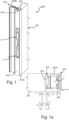
Figure 1 is an axonometric view of a possible embodiment of a handle according to the present invention mounted on a window or door frame profile;Figure 1a is an enlarged plan and scale view ofFigure 1 ; -
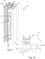
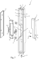
Figures 2 and 2a are views as those inFigures 1 and 1a with the handle mounted on a different window or door profile;Figures 3 to 6 are views, respectively from the front, in plan from above and below, and from the back of the handle ofFigure 1 ;Figure 7 is an axonometric and exploded view of the handle ofFigure 1 ; -
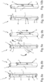
Figures 8a and 8b are axonometric views from a front angle and rear angle respectively of the handle ofFigure 1 with the operating lever in a closing position; -
Figures 9a and 9b are views as those inFigures 8a and 8b with the operating lever in a second position; -
Figures 10a and 10b are views as those inFigures 8a and 8b with the operating lever in a first opening position; -
Figures 11a, 11b and 11c are views respectively in cross-section according to the XI-XI plane, from the front and the side of the handle as shown inFigures 8a and 8b ; -
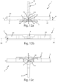
Figures 12a, 12b and 12c are views respectively in cross-section according to the XII-XII plane, from the front and the side of the handle as shown inFigures 9a and 9b ; -
Figure 12d is an enlargement of a detail ofFigure 12c ; -
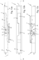
Figures 13a, 13b and 13c are views respectively in cross-section according to the XIII-XIII plane, from the front and the side of the handle as shown inFigures 10a and 10b . - With reference to the enclosed figures, it is shown a possible embodiment of a handle for operating mechanisms for opening and closing window and door frames globally indicated with 1.
- The
handle 1 is of the type that is flush-mounted into acavity 100 of a window ordoor frame 200. - As shown by way of example in
Figures 1 and2 , thehandle 1 is applicable to a window ordoor frame 200 comprising amovable sash 201 that is delimited by aperimetral profile 202. - The
perimetral profile 202 has aninternal channel 203. Components of an opening and closing mechanism are slidably housed along the longitudinal development of theinternal channel 203; these components consist ofrods 204, in particular manoeuvring rods or opening and closing rods such as, for example, the rods of a latch. - The
perimetral profile 202 then has acavity 100 in which thehandle 1 can be flush-mounted. - The
cavity 100 is obtained inside theperimetral profile 202 and, on one side, is open towards the outside of saidperimetral profile 202 so as to allow thehandle 1 to be inserted therein. On the other side, thecavity 100 is open towards the inside of theperimetral profile 202 facing and communicating, either directly (Figures 1 and 1a ) or indirectly (Figures 2 and 2a ), with theinternal channel 203 in which therods 204 slide so as to allow the connection of thehandle 1 with therods 204. - The
cavity 100 develops longitudinally parallel to theinternal channel 203. - The
perimetral profile 202 has, as known, at least one firstexternal front face sash 201 and anexternal side face 202C that is substantially perpendicular to the firstexternal front face external front faces - The
internal channel 203, in which therods 204 are slidably housed, extends parallel to theexternal side face 202C. - Preferably, the
cavity 100 is opened at theexternal side face 202C. - The
handle 1 is therefore preferably configured to be recessed at the side of theperimetral profile 202. - As is clear from the enclosed drawings, in the assembly configuration the
handle 1 is fully recessed and substantially flush with theexternal side face 202C. - The shape and dimensions of the
perimetral profile 202 androds 204 may differ from those shown in the enclosed figures, as can be immediately inferred by the person skilled in the art. - The
handle 1 comprises acase 2 which is adapted to be at least partially flush-mounted in thecavity 100 and which extends longitudinally along a first straight direction J. In the assembly configuration of thehandle 1 on theperimetral profile 202, the first direction J extends parallel to the longitudinal development direction of theinternal channel 203, i.e. parallel to the sliding direction of therods 204. - The
case 2 defines acontainment seat 3 for anoperating lever 4, in which thecontainment seat 3 is open to the outside at anopening 30. In the assembly configuration of thehandle 1 on theperimetral profile 202, thecontainment seat 3 is then accessible by a user through theopening 30. - A
slider 5 is slidably coupled to thecase 2 along a sliding direction parallel or coincident to the first sliding direction J. In the following, reference will be equally made to the first sliding direction J or the sliding direction J. Theslider 5 is provided withconnection fastenings 6 connecting to components of a mechanism for opening and closing a window or door such as, for example, therods 204. - The
operating lever 4 is adapted to slidably operate theslider 5 along the sliding direction J. - The
operating lever 4 is rotatably coupled to thecase 2 about a fulcrum whose axis is orthogonal to the first direction J and parallel to the bottom of thecase 2. - The
operating lever 4 has a grippingarm 40 and atransmission arm 41 identified by said fulcrum. - According to the present invention, the
handle 1 comprises a linkage which connects thetransmission arm 41 of theoperating lever 4 to theslider 5 and which is configured so that the length of thetransmission arm 41 varies as the angular position of theoperating lever 4 with respect to thecase 2 varies. - In particular, this linkage is configured in such a way that the length of the
transmission arm 41 decreases with the increase of the angle that the longitudinal development axis of theoperating lever 4 forms with a plane parallel to the first direction J and to the axis of the fulcrum, wherein said angle increases between a value less than 90°, said operatinglever 4 being in a first position in which it is accommodated in thecontainment seat 3, and a value substantially equal to 90°, theoperating lever 4 being in a second position angled with respect to the first position and in which it protrudes from thecontainment seat 3 with at least one part of the grippingarm 40. - The length of the
transmission arm 41 means the distance between the fulcrum of theoperating lever 4 and the point where the linkage connects with theslider 5. - In the embodiment shown in the enclosed figures, the
operating lever 4 is rotatably coupled to thecase 2 about a fulcrum defined by afirst pin 7 which is fixed to thecase 2 and which is slidably accommodated along afirst slot 70 obtained in theoperating lever 4. The longitudinal axis of thefirst pin 7 is orthogonal to the first direction J (sliding direction of the slider 5) and parallel to the plane along which therods 204 slide, i.e. the bottom plane of thecase 2. - The transmission linkage comprises a
second pin 8 which is parallel to thefirst pin 7 and is fixed to thetransmission arm 41 of theoperating lever 4. - A first longitudinal portion of the
second pin 8 is slidably inserted along asecond slot 80 obtained or defined in thecase 2. - The
second slot 80 has a curvilinear axis developing along an arc of curve and lying on a plane orthogonal to the longitudinal axes of thefirst pin 7 and thesecond pin 8. - The
second pin 8 is coupled to theslider 5 to slidably move it along the sliding direction J (first direction J). - The
second pin 8 has a second longitudinal portion that is slidably inserted along athird slot 81 obtained or defined in theslider 5. - The length of the
transmission arm 41 is defined by the distance between thefirst pin 7 and thesecond pin 8. - The
first pin 7 is completely and rigidly fastened to thecase 2. - The
first pin 7 is slidably accommodated into thefirst slot 70 obtained in the operatinglever 4. - The
first slot 70 has a straight axis and lies on a plane orthogonal to the longitudinal axis of thefirst pin 7 and thesecond pin 8. - The axis of the
first slot 70 lies along a direction perpendicular to the longitudinal axis of thefirst pin 7. - The
second pin 8 is completely and rigidly fastened to thetransmission arm 41 of the operatinglever 4. - The
second pin 8 is slidably accommodated along thesecond slot 80 obtained or defined in thecase 2 and thethird slot 81 obtained or defined in theslider 5. - As mentioned above, the
second slot 80 has a curvilinear axis, i.e. curvilinear development axis, developing along an arc of curve. - Preferably, the arc of curve is an arc of a circumference or ellipse.
- The centre of curvature CO of the arc of curve, along which the
second slot 80 is developed, lies along a straight line R orthogonal to the plane along which therods 204 slide, i.e. to the bottom plane of thecase 2, and is perpendicular to the longitudinal axis of thefirst pin 7, intersecting it. This centre of curvature CO is located along the half-line of the straight line R extending from the bottom plane of thecase 2 towards the opening 30 of thecontainment seat 3. - The arc of curve along which the
second slot 80 develops has the concavity facing theopening 30 of thecontainment seat 3. - Advantageously, the arc of curve has an arrow F less than the relative chord CD.
- Advantageously, the
second slot 80 is symmetrical to a plane passing through the longitudinal axis of thefirst pin 7 and orthogonal to the first direction J. - The
third slot 81 has a straight axis and develops along a plane orthogonal to the longitudinal axes of thefirst pin 7 andsecond pin 8. - Advantageously, the
third slot 81 has a straight axis developing along a direction orthogonal to the first direction J. - The coupling of the operating
lever 4 to thecase 2 by means of the first andsecond pins second slots handle 1 compared to the known handles with the same stroke of theslider 5. - The
first slot 70 obtained in the operatinglever 4 makes the fulcrum of the rotation of the operating lever variable, making it possible to reduce the height of the arc of circumference while keeping the chord unchanged. - By way of example only, in order to obtain a linear movement, i.e. an actual stroke of the
slider 5, of 34 mm with a total rotation of the operatinglever 4 of 180°, using a sprocket/rack or toothed sector/rack type coupling, it is necessary to dimension the sprocket or toothed sector with a primitive diameter of at least 42 mm. This results in a depth of thecase 2 and thus a handle depth of more than 42 mm. - With a linkage according to the present invention, in which two "fulcrums", i.e. two pins are present - the
first pin 7, which is fixed to thecase 2 and slidably coupled with thefirst slot 70 having a straight axis obtained in the operatinglever 4, and thesecond pin 8, which is fixed to the operatinglever 4 and slidably coupled both along thesecond slot 80 having a curvilinear axis obtained in thecase 2 and along thethird slot 81 having a straight axis obtained in the slider 5 - it is possible, with the same possible stroke (34 mm), to reduce the overall depth PF of the case to 25 mm. For the same stroke (34 mm), the height of the arc of curve (circumference, ellipse), along which theoperating lever 4 moves, is reduced. In fact, the stroke of theslider 5 is substantially equal, except for minor differences, to the length of the chord CD subtended by the arc of curve defining thesecond slot 80. The depth PF of thecase 2, on the other hand, is related to the height of that arc of curve, i.e. the arrow F. By making thesecond slot 80 as an arc of curve with an arrow F less than the chord CD, it is possible to limit the depth PF of thecase 2; in the exemplified case, with a chord CD of 34 mm, it is possible to limit the arrow to values close to approximately 12 mm. - With reference to the exemplified embodiment, the
case 2 consists of a box-shaped body whose internal volume forms thecontainment seat 3. Thecase 2 has a bottom 20 from which twolongitudinal side walls 21, 21', facing and spacing and substantially parallel to each other, except for shaping, protrude. - A pair of
transverse side walls 22, 22' joins the twolongitudinal side walls 21, 21'. - A frame delimits the
opening 30 for access to thecontainment seat 3. - The bottom 20 generally develops as planar.
-
Fasteners 9 are also provided for fixing thecase 2 to theperimetral profile 202 and, in the exemplified embodiment, they comprise grub screws and tabs that engage with the profile or with inserts housed in the profile. - The
case 2 has arectilinear guide 10 in which theslider 5 is slidably accommodated. - Preferably, the
rectilinear guide 10 is obtained on the face of the bottom 20 opposite the face facing theopening 30. - The straight guide slidably accommodates the
slider 5. - One of the two
longitudinal side walls 21, 21' is crossed through the thickness by thesecond slot 80. - The two
longitudinal side walls 21, 21' haveholes 71, 71' coaxial to each other in which thefirst pin 7 is fixed. - The operating
lever 4 develops longitudinally and thefirst slot 70 is obtained therein as well as ahole 82 in which an end of thesecond pin 8 is fixed. - The
slider 5 comprises aslide body 50 which is slidably coupled to thecase 2 along the first direction J and from which afin 51 extends or protrudes orthogonal to the longitudinal axes of thefirst pin 7 and thesecond pin 8 and with which thesecond pin 8 is coupled. - The
third slot 81 is obtained in thefin 51. - In the exemplified embodiment, the
slide body 50 is slidably accommodated in thestraight guide 10 and thefin 51 is arranged outside thecontainment seat 3, in particular, outside thelongitudinal side wall 21, 21' in which thesecond slot 80 is obtained. Advantageously, thelongitudinal side wall 21, 21' in which thesecond slot 80 is obtained has, at the latter, a profile recessed into thecontainment seat 3 to accommodate thefin 51 therein. - The
fin 51 is at least partially made of plastic. - The
fin 51 is preferably made of two components that are completely and advantageously releasably coupled to each other, for example by form and/or interlocking coupling: afirst component 510, which is obtained or fixed to theslide body 50, and asecond component 511, which is an insert that can be coupled to thefirst component 510. Thesecond component 511 is advantageously made of plastic and thethird slot 81 is formed therein. - The
connection fastenings 6 may consist of nuts, e.g. "square" nuts, which are accommodated and retained in corresponding seats obtained in theslider 5. In the exemplified case, theconnection fastenings 6 are arranged in theslide body 50. - According to a further aspect of the present invention, the
handle 1 comprises at least onefirst stop 11 of the releasable type to stop the operatinglever 4 in at least one first position. - The
first stop 11 is defined between theslider 5 and thesecond pin 8. - The
first stop 11 comprises at least oneprotuberance 111 elastically yielding to bending and obtained or defined projecting from one of the flanks delimiting saidthird slot 81 and with which thesecond pin 8 interacts. Advantageously, thefirst stop 11 comprises a pair ofprotuberances 111 elastically yielding to bending and obtained or defined projecting from the two opposite flanks delimiting thethird slot 81 and facing each other.Such protuberances 111 reduce the actual width of thethird slot 81 and delimit an endstroke seat for thesecond pin 8. Thesecond pin 8, after overcoming the elastic resistance of theprotuberances 111, by sliding into thethird slot 81, (also known as "forcing"), remains imprisoned in the endstroke seat delimited by them. As will become clear from the following description, thefirst stop 11 releasably stops thesecond pin 8 when the operatinglever 4 is in the opening and/or closing end positions of the window or door. - The
handle 1 then comprises at least a second releasable stop 12 to stop the operatinglever 4 in at least a second position. - The
second stop 12 is defined between theslider 5 and thecase 2. - The
second stop 12 comprises abending spring 120, of the flat spring or leaf spring type, which is obtained from or fixed to theslider 5 and at least onefixed protrusion 121 which is obtained from or defined in thecase 2, or vice versa, and which is adapted to counteract thebending spring 120. - The bending
spring 120 and the at least oneprotrusion 121 have respectively at least one tooth and at least one recess, or vice versa, which can be fitted (snap-fitted) into each other. - In the exemplified embodiment, the bending
spring 120 is preferably obtained in thefin 51. - The
protrusion 121 is preferably obtained as a projection from the lower face of the frame delimiting theopening 30. - As clearly shown in the enclosed figures, the
handle 1 is shaped in such a way that the operatinglever 4 is movable between at least a first position, in which it is fully housed in thecontainment seat 3, and at least a second position, which is angled with respect to the first position and in which it protrudes from thecontainment seat 3 with at least one part of thegripping arm 40. - The first position and the second position are angled at approximately 90° to each other.
- Preferably, the operating
lever 4 is movable between a pair of first positions, passing through the second position, respectively: - a first closing position and
- a first opening position,
-
Figures 8a, 8b and11a-11c show thehandle 1 with the operatinglever 4 in the first closing position. The operatinglever 4 is fully accommodated in thecontainment seat 3. Theslider 5 is retained by thefirst stop 11 at a first end of its actual stroke, wherein thesecond pin 8 is at a first end of thesecond slot 80. -
Figures 9a, 9b and12a-12d show thehandle 1 with the operatinglever 4 in the second position it reaches after an overall rotation of about 90° from the first closing position. The operatinglever 4 extends outside thecontainment seat 3 with itsgripping arm 40. Theslider 5 is retained by thesecond stop 12 substantially in the middle of its useful stroke, wherein thesecond pin 8 is substantially in the middle of thesecond slot 80. -
Figures 10a, 10b and13a-13c show thehandle 1 with the operatinglever 4 in the first opening position, which it reaches after an overall rotation of approximately 180° with respect to the first closing position. The operatinglever 4 is fully accommodated in thecontainment seat 3. Theslider 5 is retained by thefirst stop 11 at a second end of its useful stroke, wherein thesecond pin 8 is at a second end of thesecond slot 80. - The second position generally corresponds to a tilt-and-turn opening of the
wing 201. - The first opening position generally corresponds to a swing opening of the
wing 201. - It can be noted that, due to the linkage described above, the distance between the longitudinal axes of the
first pin 7 and thesecond pin 8 is not constant, but varies as the angular position of the operatinglever 4 varies. - This distance is minimum when the operating
lever 4 is in the second position (Figures 9a-9b and12a-12c ) and is maximum when the operatinglever 4 is in the first opening and closing positions respectively. - Preferably, the
handle 1 comprises acover 13 which can be fixed to thecase 2 at the external face of thelongitudinal side wall 21, 21' in which thesecond slot 80 is obtained. Thecover 3 is arranged to cover and contain at least part of theslider 5 or rather thefin 51 thereof. - All the components are made of metal, preferably zinc alloy (zamak) with the possible exclusion of the
fin 51 or thesecond component 511 thereof, which is advantageously made of plastic. - As a person skilled in the art would immediately understand, alternative embodiments equivalent to the one described are possible.
- Thus, for example, kinematic inversions and, in particular, inversions of the kinematic pairs between the various components of the
handle 1, such as the kinematic pairs connecting the operating lever to the case and/or slider, are to be considered equivalent. - Having made the rotation fulcrum of the operating
lever 4 variable, so as to reduce the radius of rotation or the length of thetransmission arm 41 when it makes a 90° rotation, switching from a flush-mounted position to a protruded position, allows to reduce the overall dimensions of thehandle 1, in particular the depth of thecase 2. - The flush-mounted handle for operating mechanisms for opening and closing windows and doors that is the object of the present invention has the advantage of having reduced the overall dimensions, in particular in terms of depth, ensuring a precise and safe operation of the movable components of the mechanisms for opening and closing window and door frames, in particular manoeuvring rods and/or opening and closing rods.
- The flush-mounted handle according to the present invention also eliminates the use of toothed wheels or sectors, sprockets and racks, ensuring normal and smooth operation of the movable components of the mechanisms for opening and closing window and door frames, in particular manoeuvring rods and/or opening and closing rods.
- The flush-mounted handle according to the present invention makes it possible to secure the operating lever, and with it, the components (rods) operated by the slider, in opening and closing limit positions and in intermediate positions thanks to the provision of first and second stops defined between the slider and the second pin and between the slider and the case, respectively. The first stop and the second stop are of the spring-loaded, snap-action type and allow a user to perceive that the correct operating lever positions have been reached for opening and closing the window or door.
- The handle as conceived herein is susceptible to many modifications and variations, all falling within the invention; furthermore, all the details are replaceable by technically equivalent elements. In practice, the materials used, as well as their dimensions, can be of any type according to the technical requirements.
Claims (18)
- Handle (1) for operating mechanisms for opening and closing windows and doors, the handle being of the type that is flush-mounted into a window or door frame cavity (100) and comprising:- a case (2) adapted to be at least partially flush-mounted into a window or door frame cavity (100) and extending longitudinally along a first straight direction (J), wherein said case (2) defines a containment seat (3) of an operating lever (4), said containment seat (3) being open outwards;- a slider (5) slidably coupled to said case (2) along a sliding direction parallel or coincident to said first direction (J) and provided with connection fastenings (6) to components of a mechanism for opening and closing window or door;- an operating lever (4) for operating the sliding motion of said slider (5) along said first direction (J), said operating lever (4) being rotatably coupled to said case (2) about a fulcrum defining on said operating lever a gripping arm (40) and a transmission arm (41), the axis of said fulcrum being orthogonal to said first direction (J) ;- a linkage connecting said transmission arm (41) of said operating lever (4) to said slider (5),- wherein the length of said transmission arm (41) varies with the angular position of said operating lever (4) with respect to said case (2).
- Handle (1) according to claim 1, wherein the length of said transmission arm (41) decreases with the increase of the angle formed by the longitudinal development axis of said operating lever (4) with a plane parallel to said first direction (J) and to the axis of said fulcrum, wherein said angle increases between a value less than 90°, said operating lever (4) being in a first position in which it is accommodated in said containment seat, and a value substantially equal to 90°, said operating lever (4) being in a second position angled with respect to the first position and in which it protrudes from said containment seat (3) with at least one part of said gripping arm (40).
- Handle (1) according to claim 1 or 2, wherein:- said fulcrum is defined by a first pin (7) fixed to said case (2) and slidably accommodated along a first slot (70) obtained in said operating lever (40), wherein the longitudinal axis of said first pin (7) is orthogonal to said first direction (J);- said linkage comprises a second pin (8) parallel to said first pin (7) and fixed to said transmission arm (41), wherein a first longitudinal portion of said second pin (8) is slidably inserted along a second slot (80) obtained or defined in said case (2), wherein said second slot (80) has a curvilinear axis developing along an arc of curve and lies on a plane orthogonal to the longitudinal axis of said first pin (7) and said second pin (8),wherein said second pin (8) is coupled to said slider (5) to make it slide along said first direction (J).
- Handle (1) according to claim 3, wherein said arc of curve is an arc of circumference or ellipse.
- Handle (1) according to claim 3 or 4, wherein said arc of curve has an arrow (F) less than the relative chord (CD).
- Handle (1) according to anyone of claims 3 to 5, wherein said second slot (80) is symmetrical to a plane passing through the longitudinal axis of said first pin (7) and orthogonal to said first direction (J).
- Handle (1) according to anyone of claims 3 to 6, wherein said first slot (70) has a straight axis and lies on a plane orthogonal to the longitudinal axis of said first pin (7) and said second pin (8).
- Handle (1) according to anyone of claims 3 to 7, wherein said second pin (8) has a second longitudinal portion slidably inserted along a third slot (81) obtained or defined in said slider (5).
- Handle (1) according to claim 8, wherein said third slot (81) has a straight axis and develops along a plane orthogonal to the longitudinal axes of said first pin (7) and said second pin (8).
- Handle (1) according to anyone of claims 3 to 9, wherein said slider (5) comprises a slide body (50) slidably coupled to said case (2) along said first direction (J), and from which a fin (51) extends or projects orthogonal to the longitudinal axes of said first pin (7) and said second pin (8), and to which the second pin (8) is coupled.
- Handle (1) according to claim 10 and claim 8 or 9, wherein said third slot (81) is obtained in said fin (51) .
- Handle (1) according to anyone of claims 8 to 11, comprising a first releasable stop (11) to stop said operating lever (4) in at least one first position, wherein said first stop comprises at least one protuberance (111) elastically yielding to bending and obtained or defined projecting from one of the flanks delimiting said third slot (81), delimiting with it an endstroke seat for said second pin (8).
- Handle (1) according to anyone of the preceding claims, comprising at least one second releasable stop (12) to stop said operating lever (4) in at least one second position, said second stop comprising at least one bending spring (12), of the type of a flat spring or leaf spring, obtained in or fixed to said slider (5) and at least one fixed protrusion (121) obtained or defined in said case (2) or vice versa, wherein said protrusion (121) is adapted to counteract said bending spring (120), said bending spring (120) and said protrusion (121) having at least one tooth and at least one recess, respectively, or vice versa, engageable with one another.
- Handle (1) according to claim 13 and anyone of claims 10 to 12, wherein said bending spring (120) is obtained in said fin (51).
- Handle (1) according to anyone of the preceding claims, wherein said operating lever (4) is movable between at least one first position, in which it is fully accommodated in said containment seat (3) and at least one second position angled with respect to the first position and in which it protrudes from said containment seat (3) with at least one part of said gripping arm (40) .
- Handle (1) according to claim 15, wherein said operating lever (4) is movable between a pair of said first positions passing through said at least one second position, said first positions defining a first closing position and a first opening position, respectively, specular to each other.
- Window and door (200) comprising:- a movable sash (201) delimited by a perimetral profile (202), said perimetral profile having:- an internal channel (203) in which components of a mechanism for opening and closing are slidably accommodated along its longitudinal development, said components being formed as rods (204),- a longitudinal cavity (100) in communication with said internal channel (203) and open outwards;- a handle (1) according to one or more of the preceding claims, wherein the case (2) of said handle is flush-mounted inside said cavity (100) with said containment seat (3) open outwards, and wherein said connection fastenings (6) of said slider (5) are connected to said rods (204).
- Window and door (200) according to claim 17, wherein said perimetral profile (202) has a first external front face (202A, 202B) substantially parallel to the plane defined by said sash (201), and a second external side face (202C) substantially perpendicular to the first face, wherein said internal channel (203) extends parallel to said second external side face (202C) and said cavity (100) is open at said second external side face (202C).
Applications Claiming Priority (1)
| Application Number | Priority Date | Filing Date | Title |
|---|---|---|---|
| IT102023000007272A IT202300007272A1 (en) | 2023-04-14 | 2023-04-14 | Control handle for opening and closing mechanisms of window frames, wherein said handle is of the type built into a cavity of a window frame. |
Publications (3)
| Publication Number | Publication Date |
|---|---|
| EP4450741A1 true EP4450741A1 (en) | 2024-10-23 |
| EP4450741C0 EP4450741C0 (en) | 2025-10-22 |
| EP4450741B1 EP4450741B1 (en) | 2025-10-22 |
Family
ID=87035983
Family Applications (1)
| Application Number | Title | Priority Date | Filing Date |
|---|---|---|---|
| EP24170099.6A Active EP4450741B1 (en) | 2023-04-14 | 2024-04-12 | Handle for operating mechanisms for opening and closing windows and doors, the handle being of the type that is flush-mounted into a window or door frame cavity |
Country Status (4)
| Country | Link |
|---|---|
| EP (1) | EP4450741B1 (en) |
| ES (1) | ES3059848T3 (en) |
| IT (1) | IT202300007272A1 (en) |
| PL (1) | PL4450741T3 (en) |
Citations (4)
| Publication number | Priority date | Publication date | Assignee | Title |
|---|---|---|---|---|
| GB339842A (en) * | 1930-01-21 | 1930-12-08 | Ernest Charles Giles | Improvements relating to sliding bolts |
| GB748188A (en) * | 1953-08-27 | 1956-04-25 | Holden & Co B Ham Ltd E | Improvements relating to bolt fastenings |
| US9145718B1 (en) * | 2014-04-22 | 2015-09-29 | I-Tek Metal Mfg. Co., Ltd. | Latch assembly with an anti-picking function |
| EP3517711B1 (en) | 2017-01-13 | 2020-07-08 | Sistemas Técnicos Del Accesorio Y Componentes, S.L. (STAC) | Windows and doors opening and closing mechanism |
-
2023
- 2023-04-14 IT IT102023000007272A patent/IT202300007272A1/en unknown
-
2024
- 2024-04-12 PL PL24170099.6T patent/PL4450741T3/en unknown
- 2024-04-12 EP EP24170099.6A patent/EP4450741B1/en active Active
- 2024-04-12 ES ES24170099T patent/ES3059848T3/en active Active
Patent Citations (4)
| Publication number | Priority date | Publication date | Assignee | Title |
|---|---|---|---|---|
| GB339842A (en) * | 1930-01-21 | 1930-12-08 | Ernest Charles Giles | Improvements relating to sliding bolts |
| GB748188A (en) * | 1953-08-27 | 1956-04-25 | Holden & Co B Ham Ltd E | Improvements relating to bolt fastenings |
| US9145718B1 (en) * | 2014-04-22 | 2015-09-29 | I-Tek Metal Mfg. Co., Ltd. | Latch assembly with an anti-picking function |
| EP3517711B1 (en) | 2017-01-13 | 2020-07-08 | Sistemas Técnicos Del Accesorio Y Componentes, S.L. (STAC) | Windows and doors opening and closing mechanism |
Also Published As
| Publication number | Publication date |
|---|---|
| EP4450741C0 (en) | 2025-10-22 |
| EP4450741B1 (en) | 2025-10-22 |
| PL4450741T3 (en) | 2026-03-23 |
| IT202300007272A1 (en) | 2024-10-14 |
| ES3059848T3 (en) | 2026-03-24 |
Similar Documents
| Publication | Publication Date | Title |
|---|---|---|
| EP2902572B1 (en) | Device for moving members for operating or for closing a window or door frame | |
| EP1918498A1 (en) | Hidden hinge | |
| EP4450741B1 (en) | Handle for operating mechanisms for opening and closing windows and doors, the handle being of the type that is flush-mounted into a window or door frame cavity | |
| EP3517711A1 (en) | Mechanism for opening and closing windows and doors | |
| CN118849724A (en) | Sliding window and vehicle | |
| HU212815B (en) | Bolt driver for orifice covers | |
| CN108979315B (en) | Multifunctional window lock | |
| NZ277062A (en) | Door closer: door rotates a spindle in closer housing which drives a cam follower along a track therein against a resiliently biased reciprocal piston: torque at spindle greater when door closed than when open | |
| EP2236717A2 (en) | Door drive having auxiliary drive mechanism | |
| CN110118040B (en) | a hinge structure | |
| CN210714223U (en) | a hinge structure | |
| CN108505842A (en) | A kind of lockset push-pull mechanism and push-pull lock | |
| EP0742332A1 (en) | Operating mechanism for espagnolette fastening system | |
| CN208518479U (en) | A lock push-pull mechanism and push-pull lock | |
| EP3988751A1 (en) | Mounting structure | |
| GB2452514A (en) | A cam lock for a window or a door | |
| CN216429274U (en) | Automatic closing mechanism for plastic-steel door and window | |
| CN215761116U (en) | Door opening and closing mechanism of double-door domestic oven with handle | |
| KR102344863B1 (en) | Moving body for sliding windows and doors horizontally and window system having the same | |
| CN206458175U (en) | push-pull lock | |
| EP1686225B1 (en) | A handle for turn opening or tilt and turn opening doors or windows. | |
| CN212054178U (en) | Lock opening and closing system and window body | |
| EP4729720A1 (en) | Espagnolette handle with cremone bolt for door and window fixtures | |
| CN113464007A (en) | Door opening and closing mechanism of double-door domestic oven without handle | |
| EP3822439A1 (en) | A locking mechanism |
Legal Events
| Date | Code | Title | Description |
|---|---|---|---|
| PUAI | Public reference made under article 153(3) epc to a published international application that has entered the european phase |
Free format text: ORIGINAL CODE: 0009012 |
|
| STAA | Information on the status of an ep patent application or granted ep patent |
Free format text: STATUS: THE APPLICATION HAS BEEN PUBLISHED |
|
| AK | Designated contracting states |
Kind code of ref document: A1 Designated state(s): AL AT BE BG CH CY CZ DE DK EE ES FI FR GB GR HR HU IE IS IT LI LT LU LV MC ME MK MT NL NO PL PT RO RS SE SI SK SM TR |
|
| STAA | Information on the status of an ep patent application or granted ep patent |
Free format text: STATUS: REQUEST FOR EXAMINATION WAS MADE |
|
| 17P | Request for examination filed |
Effective date: 20250417 |
|
| GRAP | Despatch of communication of intention to grant a patent |
Free format text: ORIGINAL CODE: EPIDOSNIGR1 |
|
| STAA | Information on the status of an ep patent application or granted ep patent |
Free format text: STATUS: GRANT OF PATENT IS INTENDED |
|
| RIC1 | Information provided on ipc code assigned before grant |
Ipc: E05C 1/06 20060101AFI20250722BHEP Ipc: E05C 7/04 20060101ALI20250722BHEP |
|
| INTG | Intention to grant announced |
Effective date: 20250730 |
|
| GRAS | Grant fee paid |
Free format text: ORIGINAL CODE: EPIDOSNIGR3 |
|
| GRAA | (expected) grant |
Free format text: ORIGINAL CODE: 0009210 |
|
| STAA | Information on the status of an ep patent application or granted ep patent |
Free format text: STATUS: THE PATENT HAS BEEN GRANTED |
|
| AK | Designated contracting states |
Kind code of ref document: B1 Designated state(s): AL AT BE BG CH CY CZ DE DK EE ES FI FR GB GR HR HU IE IS IT LI LT LU LV MC ME MK MT NL NO PL PT RO RS SE SI SK SM TR |
|
| REG | Reference to a national code |
Ref country code: CH Ref legal event code: F10 Free format text: ST27 STATUS EVENT CODE: U-0-0-F10-F00 (AS PROVIDED BY THE NATIONAL OFFICE) Effective date: 20251022 Ref country code: GB Ref legal event code: FG4D |
|
| REG | Reference to a national code |
Ref country code: DE Ref legal event code: R096 Ref document number: 602024000989 Country of ref document: DE |
|
| REG | Reference to a national code |
Ref country code: IE Ref legal event code: FG4D |
|
| U01 | Request for unitary effect filed |
Effective date: 20251104 |
|
| U07 | Unitary effect registered |
Designated state(s): AT BE BG DE DK EE FI FR IT LT LU LV MT NL PT RO SE SI Effective date: 20251110 |
|
| REG | Reference to a national code |
Ref country code: ES Ref legal event code: FG2A Ref document number: 3059848 Country of ref document: ES Kind code of ref document: T3 Effective date: 20260324 |
|
| PG25 | Lapsed in a contracting state [announced via postgrant information from national office to epo] |
Ref country code: NO Free format text: LAPSE BECAUSE OF FAILURE TO SUBMIT A TRANSLATION OF THE DESCRIPTION OR TO PAY THE FEE WITHIN THE PRESCRIBED TIME-LIMIT Effective date: 20260122 |
|
| PG25 | Lapsed in a contracting state [announced via postgrant information from national office to epo] |
Ref country code: HR Free format text: LAPSE BECAUSE OF FAILURE TO SUBMIT A TRANSLATION OF THE DESCRIPTION OR TO PAY THE FEE WITHIN THE PRESCRIBED TIME-LIMIT Effective date: 20251022 |
|
| PG25 | Lapsed in a contracting state [announced via postgrant information from national office to epo] |
Ref country code: RS Free format text: LAPSE BECAUSE OF FAILURE TO SUBMIT A TRANSLATION OF THE DESCRIPTION OR TO PAY THE FEE WITHIN THE PRESCRIBED TIME-LIMIT Effective date: 20260122 |
|
| PG25 | Lapsed in a contracting state [announced via postgrant information from national office to epo] |
Ref country code: IS Free format text: LAPSE BECAUSE OF FAILURE TO SUBMIT A TRANSLATION OF THE DESCRIPTION OR TO PAY THE FEE WITHIN THE PRESCRIBED TIME-LIMIT Effective date: 20260222 |
|
| PGFP | Annual fee paid to national office [announced via postgrant information from national office to epo] |
Ref country code: PL Payment date: 20260311 Year of fee payment: 3 |
|
| U20 | Renewal fee for the european patent with unitary effect paid |
Year of fee payment: 3 Effective date: 20260319 |