EP4450683A1 - Induction heating coil and single crystal production device using same - Google Patents
Induction heating coil and single crystal production device using same Download PDFInfo
- Publication number
- EP4450683A1 EP4450683A1 EP22907081.8A EP22907081A EP4450683A1 EP 4450683 A1 EP4450683 A1 EP 4450683A1 EP 22907081 A EP22907081 A EP 22907081A EP 4450683 A1 EP4450683 A1 EP 4450683A1
- Authority
- EP
- European Patent Office
- Prior art keywords
- slit
- induction heating
- stage surface
- heating coil
- raw material
- Prior art date
- Legal status (The legal status is an assumption and is not a legal conclusion. Google has not performed a legal analysis and makes no representation as to the accuracy of the status listed.)
- Pending
Links
Images






Classifications
-
- C—CHEMISTRY; METALLURGY
- C30—CRYSTAL GROWTH
- C30B—SINGLE-CRYSTAL GROWTH; UNIDIRECTIONAL SOLIDIFICATION OF EUTECTIC MATERIAL OR UNIDIRECTIONAL DEMIXING OF EUTECTOID MATERIAL; REFINING BY ZONE-MELTING OF MATERIAL; PRODUCTION OF A HOMOGENEOUS POLYCRYSTALLINE MATERIAL WITH DEFINED STRUCTURE; SINGLE CRYSTALS OR HOMOGENEOUS POLYCRYSTALLINE MATERIAL WITH DEFINED STRUCTURE; AFTER-TREATMENT OF SINGLE CRYSTALS OR A HOMOGENEOUS POLYCRYSTALLINE MATERIAL WITH DEFINED STRUCTURE; APPARATUS THEREFOR
- C30B13/00—Single-crystal growth by zone-melting; Refining by zone-melting
- C30B13/16—Heating of the molten zone
- C30B13/20—Heating of the molten zone by induction, e.g. hot wire technique
-
- C—CHEMISTRY; METALLURGY
- C30—CRYSTAL GROWTH
- C30B—SINGLE-CRYSTAL GROWTH; UNIDIRECTIONAL SOLIDIFICATION OF EUTECTIC MATERIAL OR UNIDIRECTIONAL DEMIXING OF EUTECTOID MATERIAL; REFINING BY ZONE-MELTING OF MATERIAL; PRODUCTION OF A HOMOGENEOUS POLYCRYSTALLINE MATERIAL WITH DEFINED STRUCTURE; SINGLE CRYSTALS OR HOMOGENEOUS POLYCRYSTALLINE MATERIAL WITH DEFINED STRUCTURE; AFTER-TREATMENT OF SINGLE CRYSTALS OR A HOMOGENEOUS POLYCRYSTALLINE MATERIAL WITH DEFINED STRUCTURE; APPARATUS THEREFOR
- C30B29/00—Single crystals or homogeneous polycrystalline material with defined structure characterised by the material or by their shape
- C30B29/02—Elements
- C30B29/06—Silicon
-
- H—ELECTRICITY
- H05—ELECTRIC TECHNIQUES NOT OTHERWISE PROVIDED FOR
- H05B—ELECTRIC HEATING; ELECTRIC LIGHT SOURCES NOT OTHERWISE PROVIDED FOR; CIRCUIT ARRANGEMENTS FOR ELECTRIC LIGHT SOURCES, IN GENERAL
- H05B6/00—Heating by electric, magnetic or electromagnetic fields
- H05B6/02—Induction heating
- H05B6/10—Induction heating apparatus, other than furnaces, for specific applications
-
- H—ELECTRICITY
- H05—ELECTRIC TECHNIQUES NOT OTHERWISE PROVIDED FOR
- H05B—ELECTRIC HEATING; ELECTRIC LIGHT SOURCES NOT OTHERWISE PROVIDED FOR; CIRCUIT ARRANGEMENTS FOR ELECTRIC LIGHT SOURCES, IN GENERAL
- H05B6/00—Heating by electric, magnetic or electromagnetic fields
- H05B6/02—Induction heating
- H05B6/36—Coil arrangements
- H05B6/40—Establishing desired heat distribution, e.g. to heat particular parts of workpieces
-
- Y—GENERAL TAGGING OF NEW TECHNOLOGICAL DEVELOPMENTS; GENERAL TAGGING OF CROSS-SECTIONAL TECHNOLOGIES SPANNING OVER SEVERAL SECTIONS OF THE IPC; TECHNICAL SUBJECTS COVERED BY FORMER USPC CROSS-REFERENCE ART COLLECTIONS [XRACs] AND DIGESTS
- Y02—TECHNOLOGIES OR APPLICATIONS FOR MITIGATION OR ADAPTATION AGAINST CLIMATE CHANGE
- Y02P—CLIMATE CHANGE MITIGATION TECHNOLOGIES IN THE PRODUCTION OR PROCESSING OF GOODS
- Y02P10/00—Technologies related to metal processing
- Y02P10/25—Process efficiency
Definitions
- An FZ method is known as a manufacturing method for a silicon single crystal.
- a part of a polycrystalline silicon raw material rod is heated to form a melting zone, and the raw material rod and a seed crystal positioned respectively above and below the melting zone are slowly lowered to grow a large single crystal above the seed crystal.
- the FZ method does not use a quartz crucible and thus can manufacture a single crystal with a low oxygen concentration.
- the FZ method uses an induction heating system to heat a polycrystalline silicon raw material.
- a magnetic field which is generated when a high-frequency current is made to flow in an induction heating coil, is applied to a silicon raw material to cause an eddy current to flow in the silicon raw material through electromagnetic induction, thereby generating Joule heat due to the eddy current, and the generated Joule heat is used to heat the silicon raw material.
- Patent Document 1 describes a method of uniformizing heating distribution on the silicon crystal side by locally forming a groove in the surface of the induction heating coil on the single crystal side so as to reduce the resistance variation of the single crystal.
- Patent Document 2 discloses a method of movably inserting an insulating member into a slit formed in the induction heating coil. Examples of the slit cross-sectional shape include a vertical type slit, an oblique type slit, and a crank type slit.
- one corner and the other corner opposite to each other across the slit have an acute angle and an obtuse angle, respectively, and current is likely to be concentrated on the acute-angled corner, resulting in very large heat generation from the slit neighborhood area having the acute-angled corner.
- the height of the upper surface on the first end side having the acute-angled corner is reduced, it is possible to reduce circumferential deviation of the heating distribution of the melt surface due to the concentration of current around the slit.
- a height variation of the melt surface of the raw material rod can be reduced to allow stable growth of a single crystal.
- a height difference between the upper and lower stage surfaces is preferably 2 mm or more.
- a thickness of the coil body in the formation area of the lower stage surface is preferably smaller than a thickness of the coil body in a formation area of the upper stage surface. This can make effective the measures of providing the height difference to the upper surface of the coil main bod to thereby reduce circumferential deviation of the heating distribution due to the concentration of current around the slit.
- the lower stage surface preferably circumferentially extends in an angular range of at least 0° to 30°.
- the lower stage surface circumferentially extends in an angular range of 0° to 90°
- the upper stage surface circumferentially extends in an angular range of at least 180° to 360°.
- a configuration may be possible in which the lower stage surface circumferentially extends in an angular range of 0° to 180°, and the upper stage surface circumferentially extends in an angular range of at least 180° to 360°. This reduces a heating distribution difference in the circumferential direction to make it possible to reduce a height variation of the melt surface of the raw material rod in the circumferential direction.
- a single crystal manufacturing apparatus is a single crystal manufacturing apparatus used to manufacture a single crystal by an FZ method, the apparatus comprising: an upper shaft that rotatably and vertically movably supports a raw material rod; a lower shaft that is disposed below the upper shaft and rotatably and vertically movably supports a seed crystal; and the above-mentioned induction heating coil according to the present invention that heats the raw material rod.
- a single crystal manufacturing apparatus capable of reducing a circumferential height variation of the melt surface of the raw material rod and thus stably growing a single crystal.
- an induction heating coil capable of reducing a circumferential height variation of the melt surface of a raw material rod and thus of stably growing a single crystal and a single crystal manufacturing apparatus using such an induction heating coil.
- FIG. 1 is a schematic view illustrating the configuration of a single crystal manufacturing apparatus according to an embodiment of the present invention.
- a single crystal manufacturing apparatus 1 is an apparatus for growing a silicon single crystal using an FZ method.
- the single crystal manufacturing apparatus 1 includes: a reaction furnace 10 accommodating a raw material rod 2, a seed crystal 3, and a silicon single crystal 4 grown on the seed crystal 3; an upper shaft 11 that rotatably and vertically movably supports the raw material rod 2; a lower shaft 12 that rotatably and vertically movably supports the seed crystal 3 and silicon single crystal 4; an induction heating coil 20 for heating the lower end portion of the raw material rod 2; a single crystal weight holder 14 that supports the weight of the silicon single crystal 4 that has been grown to a large size; and a gas doping apparatus 15 for supplying a dopant gas to a melting zone 5 (molten silicon) between the raw material rod 2 and the silicon single crystal 4.
- a reaction furnace 10 accommodating a raw material rod 2, a seed crystal 3, and a silicon single crystal 4 grown on the seed crystal 3
- an upper shaft 11 that rotatably and vertically movably supports the raw material rod
- the raw material rod 2 is made from high-purity polycrystalline silicon obtained by purifying a silicon raw material, such as monosilane or trichlorosilane, and is attached, at its upper end portion, to the lower end portion of the upper shaft 11 through a raw material holder 16.
- the seed crystal 3 is attached, at its lower end portion, to the upper end portion of the lower shaft 12 through a seed crystal holder 17.
- the upper and lower shafts 11 and 12 are each rotated and vertically moved by a not-shown drive mechanism.
- the induction heating coil 20 is a high-frequency coil of substantially one turn that surrounds the melting zone 5 or raw material rod 2 and is connected to a not illustrated high-frequency oscillator.
- the induction heating coil 20 is preferably mainly made of copper or silver.
- FIG. 2 is a schematic perspective view illustrating the configuration of the induction heating coil 20 according to a first embodiment of the present invention.
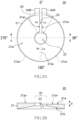
- FIGS. 3A and 3B are configuration views of the induction heating coil 20 illustrated in FIG. 2 , in which FIG. 3A is a plan view, and FIG. 3B is a cross-sectional view taken along the line X-X' in FIG. 3A .
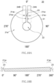
- FIG. 4A is a view illustrating the height profile of the upper surface of a coil body, and FIG. 4B is a cross-sectional view of a slit.
- the induction heating coil 20 has a coil body 21 formed of a coil conductor with a flat ring shape, an opening 22 formed at the center of the coil body 21 in plan view, a slit 23 substantially radially extending from the opening 22 to the outer peripheral end to separate one end (first end) 21e 1 of the coil body 21 in the circumferential direction and the other end (second end) 21e 2 thereof from each other, and a pair of terminal electrodes 24A and 24B connected respectively to the first and second ends 21e 1 and 21e 2 of the coil body 21.
- the coil body 21 is connected to the high-frequency oscillator through the terminal electrodes 24A and 24B.
- the outer diameter of the coil body 21 is larger than the diameter of the raw material rod 2, and the inner diameter (diameter of the opening 22) of the coil body 21 is smaller than the diameter of the raw material rod 2.
- An upper surface 21a of the coil body 21 may be a slope inclined upward from the inner circumferential side toward the outer peripheral side or may be a horizontal surface.
- a lower surface 21b of the coil body 21 may be a slope inclined downward from the inner circumferential side toward the outer peripheral side or may be a horizontal surface.
- the slit 23 penetrates the coil body 21 from the upper surface 21a to the lower surface 21b to cut one point of the coil body 21 in the circumferential direction.
- the slit 23 is formed not vertically but obliquely in cross section and, in particular, formed so as to approach the first end 21e 1 from the upper surface 21a toward the lower surface 21b.
- a corner C a1 on the upper surface 21a side of the first end 21e 1 of the coil body 21, which is positioned to the right of the slit 23, has an acute angle
- a corner C a2 on the upper surface 21a side of the second end 21e 2 of the coil body 21, which is positioned to the left of the slit 23, has an obtuse angle
- a corner C b1 on the lower surface 21b side of the first end 21e 1 has an obtuse angle
- a corner C b2 on the lower surface 21b side of the second end 21e 2 has an acute angle.
- the height of the upper surface 21a of the coil body 21 differs between the left and right of the slit 23. That is, the upper surface 21a of the coil body 21 is constituted by two surfaces facing each other across the slit 23 and having different heights : the right-side area of the slit 23 as viewed from the opening 22 is a lower stage surface 21a 1 , and the left-side area of the slit 23 is an upper stage surface 21a 2 .
- a height difference d (see FIG. 3B ) between the lower stage surface 21a 1 and the upper stage surface 21a 2 differs depending on the diameter of the raw material rod 2, it is preferably 2 mm or more and 10 mm or less.
- the height difference d is less than 2 mm, an effect of reducing a variation in the height of the melt surface of the raw material becomes insufficient, and when the height difference d exceeds 10 mm, the height variation of the melt surface may actually become large.
- the lower stage surface 21a 1 circumferentially extends in an angular range of 0° to 180° in the clockwise direction from the reference position.
- the upper stage surface 21a 2 circumferentially extends in an angular range of 180° to 360° in the clockwise direction from the reference position.
- the formation area of the lower stage surface 21a 1 is adjacent to the first end 21e 1 positioned to the right of the slit 23 and circumferentially extends from the first end 21e 1 in the clockwise direction.
- the formation area of the upper stage surface 21a 2 is adjacent to the second end 21e 2 positioned to the left of the slit 23 and circumferentially extends from the second end 21e 2 in the counterclockwise direction.
- a boundary part 21a x between the lower stage surface 21a 2 and the upper stage surface 21a 2 is located at 180° position in the clockwise (or counterclockwise) direction from the reference position.
- the lower stage surface 21a 1 is the lower stage surface 21a 1 .
- the remaining half is the upper stage surface 21a 2 .
- the formation area of the lower stage surface 21a 1 includes a slit neighborhood area 25 on the first end 21e 1 side
- the formation area of the upper stage surface 21a 2 includes a slit neighborhood area 25 on the second end 21e 2 side.
- the "slit neighborhood area” refers to a circumferential area around the slit 23 that extends to both sides of the slit 23 and can be defined as a fan-like area with an angular range of ⁇ 30° around the slit 23.
- the slit neighborhood area 25 on the first end 21e 1 side is defined as an area with an angular range of 0° to 30° circumferentially extending in the clockwise direction from the center line of the slit 23, and the slit neighborhood area 25 on the second end 21e 2 side is defined as an area with an angular range of 0° to 30° circumferentially extending in the counterclockwise direction from the center line of the slit 23 (area with an angular range of 330° to 360° circumferentially extending in the clockwise direction from the center line of the slit 23) .
- the step surface of the boundary part 21a x between the lower stage surface 21a 1 and upper stage surface 21a 2 is preferably gently inclined, and the inclination angle thereof is preferably 60° or less, particularly 45° or less.
- the inclination angle of the boundary part 21a x is 60° or less, the upper surface 21a of the coil body 21 can be easily subjected to step processing and mirror finishing.
- the thickness of the coil body 21 in the formation area of the upper stage surface 21a 2 is preferably smaller than the thickness of the coil body 21 in the formation area of the lower stage surface 21a 1 .
- FIG. 5 is a schematic view illustrating a current flow inside the coil body 21.
- the current in the induction heating coil 20 flows in a path where the distance between the pair of terminal electrodes 24A and 24B is the shortest and is concentrated around the edge of the coil body 21. Accordingly, the current flowing in the coil body 21 is concentrated in the slit neighborhood area 25, resulting in an increase in the heat generation from the slit neighborhood area 25.
- an area (slit remote area) separated remotely from the slit 23 does not undergo current concentration and is small in heat generation.
- heating in the circumferential direction becomes non-uniform at the outer peripheral portion of the raw material rod 2, making it difficult to melt the raw material rod 2 uniformly in the circumferential direction.
- any circumferential point on the raw material rod 2 is significantly heated around the slit, and thus a large amount of molten silicon is produced there. Thereafter, the point is gradually separated from the slit 23, and the heat generation from the raw material rod 2 also gradually decreases.
- the position and inclination of the center axis of the raw material rod 2 typically include a slight error, so the height variation of the raw material melt surface in the circumferential direction is considered to be influenced by a slight eccentric rotation or the like of the raw material rod 2.
- FIGS. 6A and 6B are schematic views for explaining the coil shape according to the present invention, in which FIG. 6A is a conventional coil shape, and FIG. 6B is a coil shape of the present invention.
- the upper surface 21a of the coil body 21 has the same height on both sides of the slit 23.
- the melted amount of the raw material increases in the slit neighborhood area on the first end 21e 1 side within a certain circumferential range from the position (reference position) of the slit 23, with the result that melt-up of the melt surface of the raw material rod 2 becomes large as illustrated in FIG. 11A .
- the melted amount of the raw material is small in the area excluding the slit neighborhood area on the first end 21e 1 side, with the result that the height position of the melt surface of the raw material rod 2 is lowered as illustrated in FIG. 11B .
- the melt surface of the raw material rod 2 that is opposite to the upper surface 21a of the induction heating coil 20 becomes non-uniform in height in the circumferential direction.
- the upper surface around the slit 23 having the acute-angled corner on the upper surface 21a side is the same in height as its surrounding portion, a circumferential variation in the heating distribution of the raw material further increases due to a very large amount of heat generation from the acute-angled corner.
- the height variation of the melt surface of the raw material rod 2 gradually increases as the crystal growth process advances, and when the melt surface is brought into contact with the coil surface, the crystal growth process cannot be continued. Such a phenomenon becomes conspicuous as the diameter of the raw material rod 2 increases. This is considered to be because it becomes harder for heat to be radiated from the lower end portion of the raw material rod 2 as the raw material diameter increases to make the interface shape likely to be deformed due to high temperature of the melt surface.
- the upper surface 21a of the slit neighborhood area 25 on the right side of the slit 23 and the upper surface 21a of the slit neighborhood area 25 on the left side of the slit 23 differ in height from each other.
- the upper surface 21a on the first end 21e 1 side having the acute-angled corner is lower in height than other areas, particularly, the upper surface 21a on the second end 21e 2 side.
- the slit 23 extending substantially radially from the opening 22 of the coil body 21 is formed not vertically but obliquely, and the upper surface of the slit neighborhood area 25 on the first end 21e 1 side of the slit 23 at which the corner has an acute angle is lower in height than the upper surface of the slit remote area that is remoter from the slit 23 than the slit neighborhood area 25 is.
- FIGS. 7A and 7B are views illustrating the configuration of the induction heating coil 20 according to a second embodiment of the present invention, in which FIG. 7A is a plan view, and FIG. 7B is a view illustrating the height profile of the upper surface of the coil body.
- the induction heating coil 20 is featured in that the lower stage surface 21a 1 circumferentially extends in an angular range of 0° to 30° in the clockwise direction from the position of the slit 23 and that the upper stage surface 21a 2 circumferentially extends in an angular range of 30° to 360°. That is, the lower stage surface is provided only in the slit neighborhood area 25 on the first end 21e 1 side.
- the boundary part 21a x between the lower stage surface 21a 1 and the upper stage surface 21a 2 is located at 30° position in the clockwise direction from the position of the slit 23.
- Other configurations are the same as those of the first embodiment.
- the lower stage surface 21a 1 circumferentially extends in an angular range of 0° to 30° in the clockwise direction from the position of the slit 23, making it possible to uniformize the melt surface.
- FIGS. 8A and 8B are views illustrating the configuration of the induction heating coil 20 according to a third embodiment of the present invention, in which FIG. 8A is a plan view, and FIG. 8B is a view illustrating the height profile of the upper surface of the coil body.
- the induction heating coil 20 is featured in that the lower stage surface 21a 1 circumferentially extends in an angular range of 0° to 90° in the clockwise direction from the position of the slit 23 and that the upper stage surface 21a 2 circumferentially extends in an angular range of 90° to 360°.
- the boundary part 21a x between the lower stage surface 21a 1 and the upper stage surface 21a 2 is located at 90° position in the clockwise direction from the position of the slit 23.
- Other configurations are the same as those of the first embodiment.
- the present embodiment it is possible to make the circumferential heating distribution of the raw material rod as uniform as possible as in the first embodiment. This can reduce the circumferential height variation of the melt surface of the raw material rod, which in turn can prevent contact between the melt surface and the coil surface.
- FIGS. 9A and 9B are views illustrating the configuration of the induction heating coil 20 according to a fourth embodiment of the present invention, in which FIG. 9A is a plan view, and FIG. 9B is a view illustrating the height profile of the upper surface of the coil body.
- the induction heating coil 20 is featured in that the upper surface 21a of the coil body 21 is constituted by three surfaces having mutually different heights.
- the lower stage surface 21a 1 circumferentially extends in an angular range of 0° to 90° in the clockwise direction from the position of the slit 23
- a middle stage surface 21 a3 circumferentially extends in an angular range of 90° to 180°
- the upper stage surface 21a 2 circumferentially extends in an angular range of 180° to 360°.
- a boundary part 21a x1 between the upper stage surface 21a 2 and the middle stage surface 21 a3 is located at 180° position in the clockwise direction from the position of the slit 23, and a boundary part 21a x2 between the middle stage surface 21 a3 and the lower stage surface 21a 2 is located at 90° position in the clockwise direction from the position of the slit 23.
- the height difference d between the lower stage surface 21a 2 and the upper stage surface 21a 2 is 2 mm, for example.
- the lower stage surface 21a 1 is higher in height than the middle stage surface 21 a3 by 1 mm
- the middle stage surface 21 a3 is higher in height than the upper stage surface 21a 2 by 1 mm.
- FIGS. 10A and 10B are views illustrating the configuration of the induction heating coil 20 according to a fifth embodiment of the present invention, in which FIG. 10A is a plan view, and FIG. 10B is a view illustrating the height profile of the upper surface of the coil body.
- the induction heating coil 20 is featured in that the height of the upper surface 21a of the coil body 21 linearly changes from the first end 21e 1 on the right side of the slit 23 to the second end 21e 2 on the left side of the slit 23. This is obtained by arranging an infinite number of steps for changing the height of the upper surface 21a illustrated in FIG. 9B .
- the area on the right side of the slit 23 as viewed from the opening 22 is the lower stage surface 21a 1
- the area on the left side of the slit 23 as viewed from the opening 22 is the upper stage surface 21a 2 .
- the upper surface 21a in the vicinity of the acute-angled corner C a1 is formed as the lower stage surface
- the upper surface 21a in the vicinity of the obtuse-angled corner C a2 is formed as the upper stage surface; however, since the temperature of the upper surface 21a of the slit neighborhood area 25 becomes high not only in the vicinity of the acute-angled corner C a1 but also in the vicinity of the obtuse-angled corner C a2 , the height of the upper surface 21a on both sides of the slit 23 may be reduced. That is, the lower stage surface 21a 1 may be provided both in the vicinity of the acute-angled corner C a2 and in the vicinity of the obtuse-angled corner C a2 . In this case, the thickness of the coil body 21 in the vicinity of the acute-angled corner C a1 is preferably made smaller.
- an induction heating coil (see FIG. 6A ) having a conventional structure in which the upper surface thereof on the left and right sides of the slit had no height difference and was entirely flat, and this induction heating coil was used to produce a silicon single crystal having a diameter of about 200 mm by the FZ method.
- a polycrystalline silicon rod with a diameter of 160 mm produced according to a monosilane method was adopted for the raw material rod.
- the slit 23 of the induction heating coil was an oblique slit and was formed so as to approach the right side one end of the coil from the upper surface toward the lower surface. Accordingly, the upper surface side corner at the first end had an acute angle, and the upper surface side corner at the second end positioned opposite to the acute-angled corner on the first end side across the slit had an obtuse angle.
- FIG. 13 is a graph illustrating a result of measuring the distance (interval) between the raw material melt surface and the coil upper surface. As revealed by the graph of FIG. 13 , a variation in the height of the melting zone on the raw material side was large, and the height variation of the melting zone lower surface on the raw material side became large during the crystal growth process, with the result that the distance fell below 1 mm when the length of the straight body was equal to or more than 200 mm. Although the silicon single crystal was able to be grown without problem, the melt surface was likely to contact the coil surface at any moment.
- Example 2 There was prepared an induction heating coil (see FIGS. 3A, 3B , 4A, and 4B ) according to Example 1 in which a circumferential area with an angular range of 0° to 180° in the clockwise direction from the position of the slit was defined as the lower stage surface, a circumferential area with an angular range of 180° to 360° was defined as the upper stage surface, and the height difference between the lower and upper stage surfaces was set to 2 mm.
- This induction heating coil was used to produce a silicon single crystal having a diameter of about 200 mm under the same conditions as in the Comparative Example. As a result, as revealed by the graph of FIG. 14 , the height variation of the melting zone on the raw material side was reduced. In this Example, a clearance of 3 mm or more was obtained left between the melt surface and the coil surface even in the latter part of the crystal growth process, so the single crystal was grown safely.
Landscapes
- Chemical & Material Sciences (AREA)
- Engineering & Computer Science (AREA)
- Crystallography & Structural Chemistry (AREA)
- Materials Engineering (AREA)
- Metallurgy (AREA)
- Organic Chemistry (AREA)
- Physics & Mathematics (AREA)
- Electromagnetism (AREA)
- Crystals, And After-Treatments Of Crystals (AREA)
- General Induction Heating (AREA)
Abstract
Description
- The present invention relates to an induction heating coil used to manufacture a single crystal according to an FZ (Floating Zone) method and a single crystal manufacturing apparatus using the induction heating coil.
- An FZ method is known as a manufacturing method for a silicon single crystal. In the FZ method, a part of a polycrystalline silicon raw material rod is heated to form a melting zone, and the raw material rod and a seed crystal positioned respectively above and below the melting zone are slowly lowered to grow a large single crystal above the seed crystal. Unlike a CZ (Czochralski) method, the FZ method does not use a quartz crucible and thus can manufacture a single crystal with a low oxygen concentration.
- The FZ method uses an induction heating system to heat a polycrystalline silicon raw material. In the induction heating system, a magnetic field, which is generated when a high-frequency current is made to flow in an induction heating coil, is applied to a silicon raw material to cause an eddy current to flow in the silicon raw material through electromagnetic induction, thereby generating Joule heat due to the eddy current, and the generated Joule heat is used to heat the silicon raw material.
- As to the induction heating coil, for example,
Patent Document 1 describes a method of uniformizing heating distribution on the silicon crystal side by locally forming a groove in the surface of the induction heating coil on the single crystal side so as to reduce the resistance variation of the single crystal.Patent Document 2 discloses a method of movably inserting an insulating member into a slit formed in the induction heating coil. Examples of the slit cross-sectional shape include a vertical type slit, an oblique type slit, and a crank type slit. -
- [Patent Document 1]
Japanese Patent No. 2914077 - [Patent Document 2]
Japanese Patent Laid-open Publication No. 2012-232859 - For the FZ method, there has been a demand for a raw material rod having a large diameter in order to improve the yield of a single crystal. However, an increase in the diameter of the raw material rod makes it difficult to uniformly heat the entire part in the peripheral direction of the raw material rod, thus locally increasing the melted amount of the raw material to increase a variation in the height of the melt surface of the raw material in the peripheral direction. This melt surface non-uniform in height finally contacts the coil surface to result in interruption of the manufacturing process.
- It is therefore an object of the present invention to provide an induction heating coil capable of reducing a variation in the height of the melt surface of a raw material rod and thus stably growing a single crystal and a single crystal manufacturing apparatus using such an induction heating coil.
- To solve the above problem, there is provided an induction heating coil according to the present invention used to manufacture a single crystal by an FZ method, the induction heating coil comprising an annular coil body that has an opening in the center thereof and that has first and second ends separated from each other by a slit extending in a substantially radial direction from the opening. The slit is an oblique slit that obliquely cuts the coil body from an upper surface side thereof to a lower surface side such that a corner on the upper surface side of the first end has an acute angle and that a corner on the upper surface side of the second end has an obtuse angle. The upper surface of the coil body has an upper stage surface and a lower stage surface. The lower stage surface is provided at a slit neighborhood area on the first end side, and the upper stage surface is provided in the area excluding the formation area of the lower stage surface.
- When the slit of the induction heating coil is formed obliquely in cross section, one corner and the other corner opposite to each other across the slit have an acute angle and an obtuse angle, respectively, and current is likely to be concentrated on the acute-angled corner, resulting in very large heat generation from the slit neighborhood area having the acute-angled corner. However, when the height of the upper surface on the first end side having the acute-angled corner is reduced, it is possible to reduce circumferential deviation of the heating distribution of the melt surface due to the concentration of current around the slit. Thus, a height variation of the melt surface of the raw material rod can be reduced to allow stable growth of a single crystal.
- A height difference between the upper and lower stage surfaces is preferably 2 mm or more. In this case, A thickness of the coil body in the formation area of the lower stage surface is preferably smaller than a thickness of the coil body in a formation area of the upper stage surface. This can make effective the measures of providing the height difference to the upper surface of the coil main bod to thereby reduce circumferential deviation of the heating distribution due to the concentration of current around the slit.
- The formation area of the upper stage surface preferably includes the slit neighborhood area on the second end side. This reduces a heating distribution difference between the left and right sides of the slit to make it possible to reduce circumferential deviation of the heating distribution.
- When a direction of a center line of the slit extending in a substantially radial direction from the center of the opening is assumed to be 0°, the lower stage surface preferably circumferentially extends in an angular range of at least 0° to 30°. Preferably, in this case, the lower stage surface circumferentially extends in an angular range of 0° to 90°, and the upper stage surface circumferentially extends in an angular range of at least 180° to 360°. Alternatively, a configuration may be possible in which the lower stage surface circumferentially extends in an angular range of 0° to 180°, and the upper stage surface circumferentially extends in an angular range of at least 180° to 360°. This reduces a heating distribution difference in the circumferential direction to make it possible to reduce a height variation of the melt surface of the raw material rod in the circumferential direction.
- A single crystal manufacturing apparatus according to the present invention is a single crystal manufacturing apparatus used to manufacture a single crystal by an FZ method, the apparatus comprising: an upper shaft that rotatably and vertically movably supports a raw material rod; a lower shaft that is disposed below the upper shaft and rotatably and vertically movably supports a seed crystal; and the above-mentioned induction heating coil according to the present invention that heats the raw material rod.
- According to the present invention, there can be provided a single crystal manufacturing apparatus capable of reducing a circumferential height variation of the melt surface of the raw material rod and thus stably growing a single crystal.
- According to the present invention, there can be provided an induction heating coil capable of reducing a circumferential height variation of the melt surface of a raw material rod and thus of stably growing a single crystal and a single crystal manufacturing apparatus using such an induction heating coil.
-
-
FIG. 1 is a schematic view illustrating the configuration of a single crystal manufacturing apparatus according to an embodiment of the present invention. -
FIG. 2 is a schematic perspective view illustrating the configuration of the induction heating coil according to a first embodiment of the present invention. -
FIGS. 3A and 3B are configuration views of the induction heating coil illustrated inFIG. 2 , in whichFIG. 3A is a plan view, andFIG. 3B is a cross-sectional view taken along the line X-X' inFIG. 3A . -
FIG. 4A is a view illustrating the height profile of the upper surface of a coil body, andFIG. 4B is a cross-sectional view of a slit. -
FIG. 5 is a schematic view illustrating a current flow inside the coil body. -
FIGS. 6A and 6B are schematic views for explaining the coil shape according to the present invention, in whichFIG. 6A is a conventional coil shape, andFIG. 6B is a coil shape of the present invention. -
FIGS. 7A and 7B are views illustrating the configuration of the induction heating coil according to a second embodiment of the present invention, in whichFIG. 7A is a plan view, andFIG. 7B is a view illustrating the height profile of the upper surface of the coil body. -
FIGS. 8A and 8B are views illustrating the configuration of the induction heating coil according to a third embodiment of the present invention, in whichFIG. 8A is a plan view, andFIG. 8B is a view illustrating the height profile of the upper surface of the coil body. -
FIGS. 9A and 9B are views illustrating the configuration of the induction heating coil according to a fourth embodiment of the present invention, in whichFIG. 9A is a plan view, andFIG. 9B is a view illustrating the height profile of the upper surface of the coil body. -
FIGS. 10A and 10B are views illustrating the configuration of theinduction heating coil 20 according to a fifth embodiment of the present invention, in whichFIG. 10A is a plan view, andFIG. 10B is a view illustrating the height profile of the upper surface of the coil body. -
FIGS. 11A and 11B are views illustrating an action (problems) of a conventional induction heating coil, in whichFIG. 11A is a molten state when heated in the right side of the slit, andFIG. 11B is a molten state when heated in the left side of the slit. -
FIGS.12A and 12B are views illustrating an action (problems) of the induction heating coil according to the present embodiment, in whichFIG. 11A is a molten state when heated in the right side of the slit, andFIG. 11B is a molten state when heated in the left side of the slit. -
FIG. 13 is a graph illustrating a result of measuring the distance between the raw material melt surface and the coil when growing a single crystal using the induction heating coil according to the comparative example. -
FIG. 14 is a graph illustrating a result of measuring the distance between the raw material melt surface and the coil when growing a single crystal using the induction heating coil according to the example. - Hereinafter, preferred embodiments of the present invention will be described in detail with reference to the accompanying drawings.
-
FIG. 1 is a schematic view illustrating the configuration of a single crystal manufacturing apparatus according to an embodiment of the present invention. - As illustrated in
FIG. 1 , a singlecrystal manufacturing apparatus 1 is an apparatus for growing a silicon single crystal using an FZ method. The singlecrystal manufacturing apparatus 1 includes: areaction furnace 10 accommodating araw material rod 2, aseed crystal 3, and a siliconsingle crystal 4 grown on theseed crystal 3; anupper shaft 11 that rotatably and vertically movably supports theraw material rod 2; alower shaft 12 that rotatably and vertically movably supports theseed crystal 3 and siliconsingle crystal 4; aninduction heating coil 20 for heating the lower end portion of theraw material rod 2; a singlecrystal weight holder 14 that supports the weight of the siliconsingle crystal 4 that has been grown to a large size; and agas doping apparatus 15 for supplying a dopant gas to a melting zone 5 (molten silicon) between theraw material rod 2 and the siliconsingle crystal 4. - The
raw material rod 2 is made from high-purity polycrystalline silicon obtained by purifying a silicon raw material, such as monosilane or trichlorosilane, and is attached, at its upper end portion, to the lower end portion of theupper shaft 11 through araw material holder 16. Theseed crystal 3 is attached, at its lower end portion, to the upper end portion of thelower shaft 12 through aseed crystal holder 17. The upper andlower shafts - The
induction heating coil 20 is a high-frequency coil of substantially one turn that surrounds themelting zone 5 orraw material rod 2 and is connected to a not illustrated high-frequency oscillator. Theinduction heating coil 20 is preferably mainly made of copper or silver. By making a high-frequency current to flow in theinduction heating coil 20, the lower end portion of theraw material rod 2 is induction-heated to thereby produce themelting zone 5. Theseed crystal 3 is fused to the thus producedmelting zone 5, and then theraw material rod 2 andseed crystal 3 are lowered while being rotated, whereby the siliconsingle crystal 4 can be grown from themelting zone 5. -
FIG. 2 is a schematic perspective view illustrating the configuration of theinduction heating coil 20 according to a first embodiment of the present invention.FIGS. 3A and 3B are configuration views of theinduction heating coil 20 illustrated inFIG. 2 , in whichFIG. 3A is a plan view, andFIG. 3B is a cross-sectional view taken along the line X-X' inFIG. 3A .FIG. 4A is a view illustrating the height profile of the upper surface of a coil body, andFIG. 4B is a cross-sectional view of a slit. - As illustrated in
FIG. 2 ,FIG. 3A ,FIG. 3B ,FIG. 4A and FIG. 4B , theinduction heating coil 20 has acoil body 21 formed of a coil conductor with a flat ring shape, anopening 22 formed at the center of thecoil body 21 in plan view, aslit 23 substantially radially extending from theopening 22 to the outer peripheral end to separate one end (first end) 21e1 of thecoil body 21 in the circumferential direction and the other end (second end) 21e2 thereof from each other, and a pair ofterminal electrodes coil body 21. Thecoil body 21 is connected to the high-frequency oscillator through theterminal electrodes - Typically, the outer diameter of the
coil body 21 is larger than the diameter of theraw material rod 2, and the inner diameter (diameter of the opening 22) of thecoil body 21 is smaller than the diameter of theraw material rod 2. Anupper surface 21a of thecoil body 21 may be a slope inclined upward from the inner circumferential side toward the outer peripheral side or may be a horizontal surface. Alower surface 21b of thecoil body 21 may be a slope inclined downward from the inner circumferential side toward the outer peripheral side or may be a horizontal surface. - As illustrated in
FIG. 2 andFIG. 3A , theslit 23 penetrates thecoil body 21 from theupper surface 21a to thelower surface 21b to cut one point of thecoil body 21 in the circumferential direction. Theslit 23 is formed not vertically but obliquely in cross section and, in particular, formed so as to approach the first end 21e1 from theupper surface 21a toward thelower surface 21b. Thus, as illustrated inFIG. 4B , a corner Ca1 on theupper surface 21a side of the first end 21e1 of thecoil body 21, which is positioned to the right of theslit 23, has an acute angle, and a corner Ca2 on theupper surface 21a side of the second end 21e2 of thecoil body 21, which is positioned to the left of theslit 23, has an obtuse angle. Conversely, a corner Cb1 on thelower surface 21b side of the first end 21e1 has an obtuse angle, and a corner Cb2 on thelower surface 21b side of the second end 21e2 has an acute angle. - When the
slit 23 is formed vertically in cross section, a current flowing at the first end 21e1 of thecoil body 21 along theslit 23 and a current flowing at the second end 21e2 of thecoil body 21 along theslit 23 generate a magnetic field having the same direction, so that the magnetic field is emphasized at the position around theslit 23, with the result that the magnetic field distribution of theinduction heating coil 20 has a very large deviation in the circumferential direction. On the other hand, when theslit 23 is formed obliquely in cross section, the magnetic field concentration around theslit 23 can be relaxed. - The height of the
upper surface 21a of thecoil body 21 differs between the left and right of theslit 23. That is, theupper surface 21a of thecoil body 21 is constituted by two surfaces facing each other across theslit 23 and having different heights : the right-side area of theslit 23 as viewed from theopening 22 is alower stage surface 21a1, and the left-side area of theslit 23 is anupper stage surface 21a2. - While a height difference d (see
FIG. 3B ) between thelower stage surface 21a1 and theupper stage surface 21a2 differs depending on the diameter of theraw material rod 2, it is preferably 2 mm or more and 10 mm or less. When the height difference d is less than 2 mm, an effect of reducing a variation in the height of the melt surface of the raw material becomes insufficient, and when the height difference d exceeds 10 mm, the height variation of the melt surface may actually become large. - When the direction of a center line of the
slit 23 substantially radially extending from the center of theopening 22 is assumed to be 0° (reference position), thelower stage surface 21a1 circumferentially extends in an angular range of 0° to 180° in the clockwise direction from the reference position. On the other hand, theupper stage surface 21a2 circumferentially extends in an angular range of 180° to 360° in the clockwise direction from the reference position. The formation area of thelower stage surface 21a1 is adjacent to the first end 21e1 positioned to the right of theslit 23 and circumferentially extends from the first end 21e1 in the clockwise direction. The formation area of theupper stage surface 21a2 is adjacent to the second end 21e2 positioned to the left of theslit 23 and circumferentially extends from the second end 21e2 in the counterclockwise direction. - A
boundary part 21ax between thelower stage surface 21a2 and theupper stage surface 21a2 is located at 180° position in the clockwise (or counterclockwise) direction from the reference position. Thus, about a half of the area of theupper surface 21a of thecoil body 21 is thelower stage surface 21a1, and the remaining half is theupper stage surface 21a2. - As described above, the formation area of the
lower stage surface 21a1 includes aslit neighborhood area 25 on the first end 21e1 side, and the formation area of theupper stage surface 21a2 includes aslit neighborhood area 25 on the second end 21e2 side. The "slit neighborhood area" refers to a circumferential area around theslit 23 that extends to both sides of theslit 23 and can be defined as a fan-like area with an angular range of ±30° around theslit 23. Theslit neighborhood area 25 on the first end 21e1 side is defined as an area with an angular range of 0° to 30° circumferentially extending in the clockwise direction from the center line of theslit 23, and theslit neighborhood area 25 on the second end 21e2 side is defined as an area with an angular range of 0° to 30° circumferentially extending in the counterclockwise direction from the center line of the slit 23 (area with an angular range of 330° to 360° circumferentially extending in the clockwise direction from the center line of the slit 23) . - The step surface of the
boundary part 21ax between thelower stage surface 21a1 andupper stage surface 21a2 is preferably gently inclined, and the inclination angle thereof is preferably 60° or less, particularly 45° or less. When the inclination angle of theboundary part 21ax is 60° or less, theupper surface 21a of thecoil body 21 can be easily subjected to step processing and mirror finishing. - To make the height of the
lower stage surface 21a1 lower than the height of theupper stage surface 21a2 as described above, the thickness of thecoil body 21 in the formation area of theupper stage surface 21a2 is preferably smaller than the thickness of thecoil body 21 in the formation area of thelower stage surface 21a1. -
FIG. 5 is a schematic view illustrating a current flow inside thecoil body 21. - As denoted by the arrow in
FIG. 5 , the current in theinduction heating coil 20 flows in a path where the distance between the pair ofterminal electrodes coil body 21. Accordingly, the current flowing in thecoil body 21 is concentrated in theslit neighborhood area 25, resulting in an increase in the heat generation from theslit neighborhood area 25. On the other hand, an area (slit remote area) separated remotely from theslit 23 does not undergo current concentration and is small in heat generation. Thus, heating in the circumferential direction becomes non-uniform at the outer peripheral portion of theraw material rod 2, making it difficult to melt theraw material rod 2 uniformly in the circumferential direction. Further, when theslit 23 is formed obliquely in cross section, current is concentrated on the acute-angled corner Ca1 of the two corners (Ca1 and Ca2) on both sides of theslit 23, so that the heat generation from the first end 21e1 having the acute-angled corner Ca1 becomes larger. - When the
raw material rod 2 disposed above theinduction heating coil 20 is being rotated in, for example, the clockwise direction, any circumferential point on theraw material rod 2 is significantly heated around the slit, and thus a large amount of molten silicon is produced there. Thereafter, the point is gradually separated from theslit 23, and the heat generation from theraw material rod 2 also gradually decreases. The position and inclination of the center axis of theraw material rod 2 typically include a slight error, so the height variation of the raw material melt surface in the circumferential direction is considered to be influenced by a slight eccentric rotation or the like of theraw material rod 2. -
FIGS. 6A and 6B are schematic views for explaining the coil shape according to the present invention, in whichFIG. 6A is a conventional coil shape, andFIG. 6B is a coil shape of the present invention. - As illustrated in
FIG. 6A , in the conventionalinduction heating coil 20, theupper surface 21a of thecoil body 21 has the same height on both sides of theslit 23. Thus, when theraw material rod 2 is heated using the conventionalinduction heating coil 20, the melted amount of the raw material increases in the slit neighborhood area on the first end 21e1 side within a certain circumferential range from the position (reference position) of theslit 23, with the result that melt-up of the melt surface of theraw material rod 2 becomes large as illustrated inFIG. 11A . On the other hand, the melted amount of the raw material is small in the area excluding the slit neighborhood area on the first end 21e1 side, with the result that the height position of the melt surface of theraw material rod 2 is lowered as illustrated inFIG. 11B . As a result, the melt surface of theraw material rod 2 that is opposite to theupper surface 21a of theinduction heating coil 20 becomes non-uniform in height in the circumferential direction. In particular, when the upper surface around theslit 23 having the acute-angled corner on theupper surface 21a side is the same in height as its surrounding portion, a circumferential variation in the heating distribution of the raw material further increases due to a very large amount of heat generation from the acute-angled corner. - The height variation of the melt surface of the
raw material rod 2 gradually increases as the crystal growth process advances, and when the melt surface is brought into contact with the coil surface, the crystal growth process cannot be continued. Such a phenomenon becomes conspicuous as the diameter of theraw material rod 2 increases. This is considered to be because it becomes harder for heat to be radiated from the lower end portion of theraw material rod 2 as the raw material diameter increases to make the interface shape likely to be deformed due to high temperature of the melt surface. - On the other hand, as illustrated in
FIG. 6B , in theinduction heating coil 20 according to the present embodiment, theupper surface 21a of theslit neighborhood area 25 on the right side of theslit 23 and theupper surface 21a of theslit neighborhood area 25 on the left side of theslit 23 differ in height from each other. In particular, theupper surface 21a on the first end 21e1 side having the acute-angled corner is lower in height than other areas, particularly, theupper surface 21a on the second end 21e2 side. - This can keep the
upper surface 21a on the first end 21e1 side of theslit 23 remote from amelt surface 2s of theraw material rod 2, thereby reducing heat generation of the raw material on the right side of theslit 23 irrespective of the rotation direction of theraw material rod 2, which can reduce the raw material melted amount. That is, as illustrated inFIG. 12A , excessive melt-up of the melt surface of theraw material rod 2 can be prevented in the slit neighborhood area on the right side of theslit 23. Further, as illustrated inFIG. 12B , in the slit neighborhood area on the left side of theslit 23, it is possible to prevent the raw material melt surface from being excessively reduced in height. Therefore, it is possible to make the heat generation from the raw material as uniform as possible and thus to reduce the height variation of the melt surface in the circumferential direction, which in turn can prevent contact between the melt surface and the coil surface. - As described above, in the
induction heating coil 20 according to the present embodiment, theslit 23 extending substantially radially from theopening 22 of thecoil body 21 is formed not vertically but obliquely, and the upper surface of theslit neighborhood area 25 on the first end 21e1 side of theslit 23 at which the corner has an acute angle is lower in height than the upper surface of the slit remote area that is remoter from theslit 23 than theslit neighborhood area 25 is. This makes a portion around the slit having a large heat generation slightly remote from the raw material to reduce the influence thereof, thus making it possible to reduce a circumferential variation in the heating distribution of the raw material. -
FIGS. 7A and 7B are views illustrating the configuration of theinduction heating coil 20 according to a second embodiment of the present invention, in whichFIG. 7A is a plan view, andFIG. 7B is a view illustrating the height profile of the upper surface of the coil body. - As illustrated in
FIGS. 7A and 7B , theinduction heating coil 20 according to the present embodiment is featured in that thelower stage surface 21a1 circumferentially extends in an angular range of 0° to 30° in the clockwise direction from the position of theslit 23 and that theupper stage surface 21a2 circumferentially extends in an angular range of 30° to 360°. That is, the lower stage surface is provided only in theslit neighborhood area 25 on the first end 21e1 side. Theboundary part 21ax between thelower stage surface 21a1 and theupper stage surface 21a2 is located at 30° position in the clockwise direction from the position of theslit 23. Other configurations are the same as those of the first embodiment. - When the end position in the circumferential direction of the formation area of the
lower stage surface 21a1 is less than 30° in an angular position as described above, an effect of uniformizing the melt surface obtained by reducing the height of theupper surface 21a on the first end 21e1 side of theslit 23 becomes insufficient, thus increasing the probability of contact between the raw material melt surface and the coil surface. However, in the present embodiment, thelower stage surface 21a1 circumferentially extends in an angular range of 0° to 30° in the clockwise direction from the position of theslit 23, making it possible to uniformize the melt surface. -
FIGS. 8A and 8B are views illustrating the configuration of theinduction heating coil 20 according to a third embodiment of the present invention, in whichFIG. 8A is a plan view, andFIG. 8B is a view illustrating the height profile of the upper surface of the coil body. - As illustrated in
FIGS. 8A and 8B , theinduction heating coil 20 according to the present embodiment is featured in that thelower stage surface 21a1 circumferentially extends in an angular range of 0° to 90° in the clockwise direction from the position of theslit 23 and that theupper stage surface 21a2 circumferentially extends in an angular range of 90° to 360°. Theboundary part 21ax between thelower stage surface 21a1 and theupper stage surface 21a2 is located at 90° position in the clockwise direction from the position of theslit 23. Other configurations are the same as those of the first embodiment. - According to the present embodiment, it is possible to make the circumferential heating distribution of the raw material rod as uniform as possible as in the first embodiment. This can reduce the circumferential height variation of the melt surface of the raw material rod, which in turn can prevent contact between the melt surface and the coil surface.
-
FIGS. 9A and 9B are views illustrating the configuration of theinduction heating coil 20 according to a fourth embodiment of the present invention, in whichFIG. 9A is a plan view, andFIG. 9B is a view illustrating the height profile of the upper surface of the coil body. - As illustrated in
FIGS. 9A and 9B , theinduction heating coil 20 according to the present embodiment is featured in that theupper surface 21a of thecoil body 21 is constituted by three surfaces having mutually different heights. In more detail, thelower stage surface 21a1 circumferentially extends in an angular range of 0° to 90° in the clockwise direction from the position of theslit 23, amiddle stage surface 21a3 circumferentially extends in an angular range of 90° to 180°, and theupper stage surface 21a2 circumferentially extends in an angular range of 180° to 360°. Aboundary part 21ax1 between theupper stage surface 21a2 and themiddle stage surface 21a3 is located at 180° position in the clockwise direction from the position of theslit 23, and aboundary part 21ax2 between themiddle stage surface 21a3 and thelower stage surface 21a2 is located at 90° position in the clockwise direction from the position of theslit 23. - The height difference d between the
lower stage surface 21a2 and theupper stage surface 21a2 is 2 mm, for example. Thelower stage surface 21a1 is higher in height than themiddle stage surface 21a3 by 1 mm, and themiddle stage surface 21a3 is higher in height than theupper stage surface 21a2 by 1 mm. By thus providing themiddle stage surface 21a3 between thelower stage surface 21a2 and theupper stage surface 21a2 and setting more finely a height change of theupper surface 21a of thecoil body 21 in the circumferential direction, it is possible to smooth a circumferential change in the heating temperature of theraw material rod 2. -
FIGS. 10A and 10B are views illustrating the configuration of theinduction heating coil 20 according to a fifth embodiment of the present invention, in whichFIG. 10A is a plan view, andFIG. 10B is a view illustrating the height profile of the upper surface of the coil body. - As illustrated in
FIGS. 10A and 10B , theinduction heating coil 20 according to the present embodiment is featured in that the height of theupper surface 21a of thecoil body 21 linearly changes from the first end 21e1 on the right side of theslit 23 to the second end 21e2 on the left side of theslit 23. This is obtained by arranging an infinite number of steps for changing the height of theupper surface 21a illustrated inFIG. 9B . Thus, the area on the right side of theslit 23 as viewed from theopening 22 is thelower stage surface 21a1, and the area on the left side of theslit 23 as viewed from theopening 22 is theupper stage surface 21a2. According to the present embodiment, it is possible to smooth a circumferential change in the heating temperature of theraw material rod 2. - While the preferred embodiments of the present invention have been described, the present invention is not limited to the above embodiments, and various modifications may be made within the scope of the present invention, and all such modifications are included in the present invention.
- For example, in the above embodiments, the
upper surface 21a in the vicinity of the acute-angled corner Ca1 is formed as the lower stage surface, and theupper surface 21a in the vicinity of the obtuse-angled corner Ca2 is formed as the upper stage surface; however, since the temperature of theupper surface 21a of theslit neighborhood area 25 becomes high not only in the vicinity of the acute-angled corner Ca1 but also in the vicinity of the obtuse-angled corner Ca2, the height of theupper surface 21a on both sides of theslit 23 may be reduced. That is, thelower stage surface 21a1 may be provided both in the vicinity of the acute-angled corner Ca2 and in the vicinity of the obtuse-angled corner Ca2. In this case, the thickness of thecoil body 21 in the vicinity of the acute-angled corner Ca1 is preferably made smaller. - There was prepared an induction heating coil (see
FIG. 6A ) having a conventional structure in which the upper surface thereof on the left and right sides of the slit had no height difference and was entirely flat, and this induction heating coil was used to produce a silicon single crystal having a diameter of about 200 mm by the FZ method. A polycrystalline silicon rod with a diameter of 160 mm produced according to a monosilane method was adopted for the raw material rod. Theslit 23 of the induction heating coil was an oblique slit and was formed so as to approach the right side one end of the coil from the upper surface toward the lower surface. Accordingly, the upper surface side corner at the first end had an acute angle, and the upper surface side corner at the second end positioned opposite to the acute-angled corner on the first end side across the slit had an obtuse angle. -
FIG. 13 is a graph illustrating a result of measuring the distance (interval) between the raw material melt surface and the coil upper surface. As revealed by the graph ofFIG. 13 , a variation in the height of the melting zone on the raw material side was large, and the height variation of the melting zone lower surface on the raw material side became large during the crystal growth process, with the result that the distance fell below 1 mm when the length of the straight body was equal to or more than 200 mm. Although the silicon single crystal was able to be grown without problem, the melt surface was likely to contact the coil surface at any moment. - There was prepared an induction heating coil (see
FIGS. 3A, 3B ,4A, and 4B ) according to Example 1 in which a circumferential area with an angular range of 0° to 180° in the clockwise direction from the position of the slit was defined as the lower stage surface, a circumferential area with an angular range of 180° to 360° was defined as the upper stage surface, and the height difference between the lower and upper stage surfaces was set to 2 mm. This induction heating coil was used to produce a silicon single crystal having a diameter of about 200 mm under the same conditions as in the Comparative Example. As a result, as revealed by the graph ofFIG. 14 , the height variation of the melting zone on the raw material side was reduced. In this Example, a clearance of 3 mm or more was obtained left between the melt surface and the coil surface even in the latter part of the crystal growth process, so the single crystal was grown safely. -
- 1: Single crystal manufacturing apparatus
- 2: Raw material rod
- 2s: Melt surface of raw material rod
- 3: Seed crystal
- 4: Silicon single crystal
- 5: Melting zone
- 10: Reaction furnace
- 11: Upper shaft
- 12: Lower shaft
- 14: Single crystal weight holder
- 15: Gas doping apparatus
- 16: Raw material holder
- 17: Seed crystal holder
- 20: Induction heating coil
- 21: Coil body
- 21a: Upper surface of coil body
- 21a1 Lower stage surface
- 21a2: Upper stage surface
- 21a3: Middle stage surface
- 21ax, 21ax1, 21ax2: Boundary part (step)
- 21b: Lower surface of coil body
- 21e1: First end of coil body
- 21e2: Second end of coil body
- 22: Opening
- 23: Slit
- 24A, 24B: Terminal electrode
- 25: Slit neighborhood area
- Ca1, Ca2: Corner
- Cb1, Cb2: Corner
Claims (8)
- An induction heating coil used to manufacture a single crystal by an FZ method, comprising:an annular coil body that has an opening in the center thereof and that has first and second ends separated from each other by a slit extending in a substantially radial direction from the opening, whereinthe slit is an oblique slit that obliquely cuts the coil body from an upper surface side thereof to a lower surface side such that a corner on the upper surface side of the first end has an acute angle and that a corner on the upper surface side of the second end has an obtuse angle,the upper surface of the coil body has an upper stage surface and a lower stage surface,the lower stage surface is provided at a slit neighborhood area on the first end side, andthe upper stage surface is provided in an area excluding a formation area of the lower stage surface.
- The induction heating coil according to Claim 1, wherein
a height difference between the upper and lower stage surfaces is 2 mm or more. - The induction heating coil according to Claim 1, wherein
a thickness of the coil body in the formation area of the lower stage surface is smaller than a thickness of the coil body in a formation area of the upper stage surface. - The induction heating coil according to Claim 1, wherein
the formation area of the upper stage surface includes the slit neighborhood area on the second end side. - The induction heating coil according to Claim 1, wherein
when a direction of a center line of the slit extending in a substantially radial direction from the center of the opening is assumed to be 0°, the lower stage surface circumferentially extends in an angular range of at least 0° to 30°. - The induction heating coil according to Claim 5, wherein
the lower stage surface circumferentially extends in an angular range of 0° to 90°, and the upper stage surface circumferentially extends in an angular range of at least 180° to 360°. - The induction heating coil according to Claim 5, wherein
the lower stage surface circumferentially extends in an angular range of 0° to 180°, and the upper stage surface circumferentially extends in an angular range of at least 180° to 360°. - A single crystal manufacturing apparatus used to manufacture a single crystal by an FZ method, comprising:an upper shaft that rotatably and vertically movably supports a raw material rod;a lower shaft that is disposed below the upper shaft and rotatably and vertically movably supports a seed crystal; andthe induction heating coil according to Claim 1 that heats the raw material rod.
Applications Claiming Priority (2)
| Application Number | Priority Date | Filing Date | Title |
|---|---|---|---|
| JP2021202509 | 2021-12-14 | ||
| PCT/JP2022/041537 WO2023112550A1 (en) | 2021-12-14 | 2022-11-08 | Induction heating coil and single crystal production device using same |
Publications (2)
| Publication Number | Publication Date |
|---|---|
| EP4450683A1 true EP4450683A1 (en) | 2024-10-23 |
| EP4450683A4 EP4450683A4 (en) | 2025-11-19 |
Family
ID=86774487
Family Applications (1)
| Application Number | Title | Priority Date | Filing Date |
|---|---|---|---|
| EP22907081.8A Pending EP4450683A4 (en) | 2021-12-14 | 2022-11-08 | INDUCTION HEATING COIL AND DEVICE FOR THE PRODUCTION OF SINGLE CRYSTALS WITH IT |
Country Status (4)
| Country | Link |
|---|---|
| EP (1) | EP4450683A4 (en) |
| JP (1) | JP7726297B2 (en) |
| CN (1) | CN118414454A (en) |
| WO (1) | WO2023112550A1 (en) |
Family Cites Families (7)
| Publication number | Priority date | Publication date | Assignee | Title |
|---|---|---|---|---|
| JPS6448391A (en) * | 1987-04-27 | 1989-02-22 | Shinetsu Handotai Kk | Single winding induction heating coil used in floating zone melting method |
| JP2914077B2 (en) | 1993-02-26 | 1999-06-28 | 信越半導体株式会社 | High frequency induction heating coil |
| JP2820027B2 (en) * | 1994-05-24 | 1998-11-05 | 信越半導体株式会社 | Semiconductor single crystal growth method |
| JP3127981B2 (en) * | 1995-01-31 | 2001-01-29 | 信越半導体株式会社 | High frequency induction heating device |
| JP5505365B2 (en) | 2011-04-28 | 2014-05-28 | 信越半導体株式会社 | Insulating member for preventing discharge in induction heating coil, single crystal manufacturing apparatus and single crystal manufacturing method using the same |
| WO2021005853A1 (en) * | 2019-07-05 | 2021-01-14 | 株式会社Sumco | Induction-heating coil and single crystal production device using same |
| JP7552498B2 (en) * | 2021-05-18 | 2024-09-18 | 株式会社Sumco | Induction heating coil, single crystal manufacturing apparatus using the same, and method for manufacturing single crystal |
-
2022
- 2022-11-08 JP JP2023567612A patent/JP7726297B2/en active Active
- 2022-11-08 EP EP22907081.8A patent/EP4450683A4/en active Pending
- 2022-11-08 WO PCT/JP2022/041537 patent/WO2023112550A1/en not_active Ceased
- 2022-11-08 CN CN202280083091.2A patent/CN118414454A/en active Pending
Also Published As
| Publication number | Publication date |
|---|---|
| EP4450683A4 (en) | 2025-11-19 |
| CN118414454A (en) | 2024-07-30 |
| JP7726297B2 (en) | 2025-08-20 |
| JPWO2023112550A1 (en) | 2023-06-22 |
| WO2023112550A1 (en) | 2023-06-22 |
Similar Documents
| Publication | Publication Date | Title |
|---|---|---|
| KR101997565B1 (en) | Method for producing monocrystalline silicon | |
| KR102505546B1 (en) | semiconductor crystal growth device | |
| JP6491763B2 (en) | Method for producing silicon single crystal ingot | |
| JP5131170B2 (en) | Upper heater for single crystal production, single crystal production apparatus and single crystal production method | |
| JPH07326472A (en) | High-frequency induction heating coil | |
| JPH0825836B2 (en) | Silicon single crystal manufacturing equipment | |
| JP7611193B2 (en) | Polycrystalline silicon rod, polycrystalline silicon rod and method for producing same | |
| KR101391057B1 (en) | Single-crystal semiconductor fabrication device and fabrication method | |
| JP7120464B2 (en) | Induction heating coil and single crystal manufacturing apparatus using the same | |
| EP4092167A1 (en) | Induction heating coil and single crystal manufacturing apparatus and method using the induction heating coil | |
| JPH08268792A (en) | High-frequency induction heater | |
| JP7726297B2 (en) | Induction heating coil and single crystal manufacturing device using the same | |
| TWI784314B (en) | Manufacturing method of single crystal silicon | |
| CN115044966B (en) | Heater and working method thereof | |
| JP7259722B2 (en) | Single crystal manufacturing apparatus and single crystal manufacturing method | |
| KR20030069822A (en) | Process for producing a highly doped silicon single crystal | |
| JP7655351B2 (en) | Heating device, silicon single crystal manufacturing device, and silicon single crystal manufacturing method | |
| CN112921394A (en) | Induction heating coil and single crystal manufacturing apparatus using the same | |
| JP2022101775A (en) | Induction heating coil and apparatus for manufacturing single crystal using the same | |
| JP2020037499A (en) | Heat shield member, apparatus for pulling single crystal and method for manufacturing single crystal | |
| TW202223175A (en) | Method for producing single crystal, magnetic field generator and apparatus for producing single crystal | |
| JP2002249397A (en) | Method for producing silicon single crystal | |
| CN121002233A (en) | Methods and apparatus for manufacturing monocrystalline silicon |
Legal Events
| Date | Code | Title | Description |
|---|---|---|---|
| STAA | Information on the status of an ep patent application or granted ep patent |
Free format text: STATUS: THE INTERNATIONAL PUBLICATION HAS BEEN MADE |
|
| PUAI | Public reference made under article 153(3) epc to a published international application that has entered the european phase |
Free format text: ORIGINAL CODE: 0009012 |
|
| STAA | Information on the status of an ep patent application or granted ep patent |
Free format text: STATUS: REQUEST FOR EXAMINATION WAS MADE |
|
| 17P | Request for examination filed |
Effective date: 20240702 |
|
| AK | Designated contracting states |
Kind code of ref document: A1 Designated state(s): AL AT BE BG CH CY CZ DE DK EE ES FI FR GB GR HR HU IE IS IT LI LT LU LV MC ME MK MT NL NO PL PT RO RS SE SI SK SM TR |
|
| DAV | Request for validation of the european patent (deleted) | ||
| DAX | Request for extension of the european patent (deleted) | ||
| A4 | Supplementary search report drawn up and despatched |
Effective date: 20251020 |
|
| RIC1 | Information provided on ipc code assigned before grant |
Ipc: C30B 13/20 20060101AFI20251014BHEP Ipc: H05B 6/10 20060101ALI20251014BHEP Ipc: H05B 6/40 20060101ALI20251014BHEP Ipc: C30B 29/06 20060101ALI20251014BHEP |