EP4450435A1 - Winding switching and strip receiving module, winding switching and automatic strip receiving mechanism, winding device, and production line - Google Patents
Winding switching and strip receiving module, winding switching and automatic strip receiving mechanism, winding device, and production line Download PDFInfo
- Publication number
- EP4450435A1 EP4450435A1 EP23839090.0A EP23839090A EP4450435A1 EP 4450435 A1 EP4450435 A1 EP 4450435A1 EP 23839090 A EP23839090 A EP 23839090A EP 4450435 A1 EP4450435 A1 EP 4450435A1
- Authority
- EP
- European Patent Office
- Prior art keywords
- belt receiving
- assembly
- protection cover
- receiving roller
- roller
- Prior art date
- Legal status (The legal status is an assumption and is not a legal conclusion. Google has not performed a legal analysis and makes no representation as to the accuracy of the status listed.)
- Pending
Links
Images


Classifications
-
- B—PERFORMING OPERATIONS; TRANSPORTING
- B65—CONVEYING; PACKING; STORING; HANDLING THIN OR FILAMENTARY MATERIAL
- B65H—HANDLING THIN OR FILAMENTARY MATERIAL, e.g. SHEETS, WEBS, CABLES
- B65H19/00—Changing the web roll
- B65H19/10—Changing the web roll in unwinding mechanisms or in connection with unwinding operations
- B65H19/18—Attaching, e.g. pasting, the replacement web to the expiring web
- B65H19/1805—Flying splicing, i.e. the expiring web moving during splicing contact
- B65H19/181—Flying splicing, i.e. the expiring web moving during splicing contact taking place on the replacement roll
-
- B—PERFORMING OPERATIONS; TRANSPORTING
- B65—CONVEYING; PACKING; STORING; HANDLING THIN OR FILAMENTARY MATERIAL
- B65H—HANDLING THIN OR FILAMENTARY MATERIAL, e.g. SHEETS, WEBS, CABLES
- B65H19/00—Changing the web roll
- B65H19/10—Changing the web roll in unwinding mechanisms or in connection with unwinding operations
- B65H19/18—Attaching, e.g. pasting, the replacement web to the expiring web
- B65H19/1842—Attaching, e.g. pasting, the replacement web to the expiring web standing splicing, i.e. the expiring web being stationary during splicing contact
- B65H19/1852—Attaching, e.g. pasting, the replacement web to the expiring web standing splicing, i.e. the expiring web being stationary during splicing contact taking place at a distance from the replacement roll
-
- B—PERFORMING OPERATIONS; TRANSPORTING
- B65—CONVEYING; PACKING; STORING; HANDLING THIN OR FILAMENTARY MATERIAL
- B65H—HANDLING THIN OR FILAMENTARY MATERIAL, e.g. SHEETS, WEBS, CABLES
- B65H19/00—Changing the web roll
- B65H19/22—Changing the web roll in winding mechanisms or in connection with winding operations
- B65H19/26—Cutting-off the web running to the wound web roll
-
- H—ELECTRICITY
- H01—ELECTRIC ELEMENTS
- H01M—PROCESSES OR MEANS, e.g. BATTERIES, FOR THE DIRECT CONVERSION OF CHEMICAL ENERGY INTO ELECTRICAL ENERGY
- H01M10/00—Secondary cells; Manufacture thereof
- H01M10/04—Construction or manufacture in general
- H01M10/0404—Machines for assembling batteries
-
- B—PERFORMING OPERATIONS; TRANSPORTING
- B65—CONVEYING; PACKING; STORING; HANDLING THIN OR FILAMENTARY MATERIAL
- B65H—HANDLING THIN OR FILAMENTARY MATERIAL, e.g. SHEETS, WEBS, CABLES
- B65H19/00—Changing the web roll
- B65H19/10—Changing the web roll in unwinding mechanisms or in connection with unwinding operations
- B65H19/18—Attaching, e.g. pasting, the replacement web to the expiring web
- B65H19/1857—Support arrangement of web rolls
- B65H19/1873—Support arrangement of web rolls with two stationary roll supports carrying alternately the replacement and the expiring roll
-
- B—PERFORMING OPERATIONS; TRANSPORTING
- B65—CONVEYING; PACKING; STORING; HANDLING THIN OR FILAMENTARY MATERIAL
- B65H—HANDLING THIN OR FILAMENTARY MATERIAL, e.g. SHEETS, WEBS, CABLES
- B65H19/00—Changing the web roll
- B65H19/10—Changing the web roll in unwinding mechanisms or in connection with unwinding operations
- B65H19/20—Cutting-off the expiring web
-
- B—PERFORMING OPERATIONS; TRANSPORTING
- B65—CONVEYING; PACKING; STORING; HANDLING THIN OR FILAMENTARY MATERIAL
- B65H—HANDLING THIN OR FILAMENTARY MATERIAL, e.g. SHEETS, WEBS, CABLES
- B65H19/00—Changing the web roll
- B65H19/22—Changing the web roll in winding mechanisms or in connection with winding operations
- B65H19/2207—Changing the web roll in winding mechanisms or in connection with winding operations the web roll being driven by a winding mechanism of the centre or core drive type
-
- B—PERFORMING OPERATIONS; TRANSPORTING
- B65—CONVEYING; PACKING; STORING; HANDLING THIN OR FILAMENTARY MATERIAL
- B65H—HANDLING THIN OR FILAMENTARY MATERIAL, e.g. SHEETS, WEBS, CABLES
- B65H19/00—Changing the web roll
- B65H19/22—Changing the web roll in winding mechanisms or in connection with winding operations
- B65H19/26—Cutting-off the web running to the wound web roll
- B65H19/265—Cutting-off the web running to the wound web roll using a cutting member moving linearly in a plane parallel to the surface of the web and along a direction crossing the web
-
- B—PERFORMING OPERATIONS; TRANSPORTING
- B65—CONVEYING; PACKING; STORING; HANDLING THIN OR FILAMENTARY MATERIAL
- B65H—HANDLING THIN OR FILAMENTARY MATERIAL, e.g. SHEETS, WEBS, CABLES
- B65H19/00—Changing the web roll
- B65H19/22—Changing the web roll in winding mechanisms or in connection with winding operations
- B65H19/29—Securing the trailing end of the wound web to the web roll
-
- B—PERFORMING OPERATIONS; TRANSPORTING
- B65—CONVEYING; PACKING; STORING; HANDLING THIN OR FILAMENTARY MATERIAL
- B65H—HANDLING THIN OR FILAMENTARY MATERIAL, e.g. SHEETS, WEBS, CABLES
- B65H2404/00—Parts for transporting or guiding the handled material
- B65H2404/60—Other elements in face contact with handled material
- B65H2404/68—Other elements in face contact with handled material reciprocating in transport direction
-
- B—PERFORMING OPERATIONS; TRANSPORTING
- B65—CONVEYING; PACKING; STORING; HANDLING THIN OR FILAMENTARY MATERIAL
- B65H—HANDLING THIN OR FILAMENTARY MATERIAL, e.g. SHEETS, WEBS, CABLES
- B65H2801/00—Application field
- B65H2801/72—Fuel cell manufacture
-
- Y—GENERAL TAGGING OF NEW TECHNOLOGICAL DEVELOPMENTS; GENERAL TAGGING OF CROSS-SECTIONAL TECHNOLOGIES SPANNING OVER SEVERAL SECTIONS OF THE IPC; TECHNICAL SUBJECTS COVERED BY FORMER USPC CROSS-REFERENCE ART COLLECTIONS [XRACs] AND DIGESTS
- Y02—TECHNOLOGIES OR APPLICATIONS FOR MITIGATION OR ADAPTATION AGAINST CLIMATE CHANGE
- Y02E—REDUCTION OF GREENHOUSE GAS [GHG] EMISSIONS, RELATED TO ENERGY GENERATION, TRANSMISSION OR DISTRIBUTION
- Y02E60/00—Enabling technologies; Technologies with a potential or indirect contribution to GHG emissions mitigation
- Y02E60/10—Energy storage using batteries
Definitions
- the present application relates to the technical field of material belt winding, and in particular to a reel changing and belt receiving module, a reel changing and automatic belt receiving mechanism, a winding device and a production line.
- the processes of fully automatic winding, coating and die-cutting all include the process of winding and unwinding the pole piece material belt.
- full or empty rolls may be encountered, and at this time, the reel needs to be changed.
- the common way of changing reels is manual reel changing or through corresponding mechanisms. Due to structural or design defects, the existing reel changing mechanism needs to be stopped when changing reels, which affects the work efficiency; while the manual way of changing reels has the disadvantage of low reel changing efficiency, and the device needs to be stopped when changing reels manually, which further affects the overall work efficiency of the device, greatly increases the labor and time costs, and affects the production benefits of the enterprise.
- the existing manual reel changing or mechanism reel changing has technical defects such as low reel changing efficiency, high time and labor costs, device shutdown, and affecting the work efficiency of the device, which seriously affect the further development and promotion application of the field.
- the purpose of the present application is to provide a new technical solution to solve the existing technical problems.
- the present application provides a reel changing and belt receiving module, a reel changing and automatic belt receiving mechanism, a winding device and a production line, which solve the technical defects of the existing technology such as the need for device shutdown, affecting the working efficiency of the device, and high labor and time costs.
- a cutter protection cover configured to rotate around the central shaft of the belt receiving roller is provided on a side of the belt receiving roller; a protection cover driven assembly is provided on an installation seat at one end of the belt receiving roller, and the protection cover driven assembly is configured to drive the cutter protection cover to rotate around the central shaft of the belt receiving roller.
- the protection cover driven assembly includes a protection cover driven motor
- the belt receiving roller driven assembly includes a belt receiving roller driven motor, a belt receiving roller reducer provided at an output end of the belt receiving roller driven motor, and a shaft coupling connected between an output end of the belt receiving roller reducer and one end of a rotation shaft of the belt receiving roller.
- a protection cover installation plate is rotatably provided on the rotation shaft of the belt receiving roller, and the cutter protection cover is installed on the protection cover installation plate;
- a protection cover transmission assembly is provided between an output end of the protection cover driven assembly and one of the protection cover installation plates, and the protection cover driven assembly is configured to drive the protection cover installation plate and the cutter protection cover to rotate through the protection cover transmission assembly.
- the protection cover transmission assembly includes an active synchronization wheel provided at the output end of the protection cover driven assembly, a driven synchronization wheel provided on one of the protection cover installation plates, and a synchronization belt wound between the active synchronization wheel and the driven synchronization wheel; and the protection cover driven assembly is configured to drive the protection cover installation plate and the cutter protection cover to rotate through the active synchronization wheel, the synchronization belt, and the driven synchronization wheel.
- the cutter assembly includes a cutter installation seat fixedly installed on the installation shaft of the belt receiving roller, a cutter installation plate fixed on the cutter installation seat, and a sawtooth cutter fixedly installed on the cutter installation plate.
- the output end of the horizontal moving assembly is provided with a horizontal moving installation seat, and the forward and backward moving assembly is directly or indirectly installed on the horizontal moving installation seat.
- the output end of the horizontal moving assembly is provided with a swing adjustment assembly, and the forward and backward moving assembly is provided at an output end of the swing adjustment assembly.
- the swing adjustment assembly includes a swing driven motor, a swing reducer provided at an output end of the swing driven motor, and a swing installation plate provided on an output shaft of the swing reducer; the forward and backward moving assembly is fixedly installed on the swing installation plate, and the swing driven motor is configured to drive the swing installation plate to swing through the swing reducer and further drive the forward and backward moving assembly to swing through the swing installation plate.
- the output end of the forward and backward moving assembly is provided with a belt receiving roller installation seat, and the belt receiving roller and the belt receiving roller driven assembly are installed on the belt receiving roller installation seat.
- the horizontal moving assembly includes a horizontal moving guide rail and a horizontal moving driven motor; the forward and backward moving assembly is a pneumatic moving assembly, and the output end of the forward and backward moving assembly is provided with a forward and backward moving installation plate.
- the present application also provides:
- pairs of rotation rollers are provided to convey material belt products, and the first roller cylinder and the second roller cylinder are configured for rolling and cooperating for rolling work in different time periods.
- the present application also provides a winding device, including: the reel changing and belt receiving module; or the reel changing and automatic belt receiving mechanism.
- the present application also provides a production line, a device of the production line includes the reel changing and belt receiving module, or the device of the production line includes the reel changing and automatic belt receiving mechanism, or the production line adopts the winding device.
- the beneficial effects of the present application are as follows: the present application provides a reel changing and belt receiving module, a reel changing and automatic belt receiving mechanism, a winding device and a production line, which can realize non-stop and automatic reel changing in actual production, which not only saves labor and time costs, but also greatly improves the working efficiency of the device, reduces production costs, and improves the production benefits of the enterprise.
- the reel changing and belt receiving module solve the technical defects in related art, such as the need for device shutdown, affecting device working efficiency, and high labor and time costs.
- the present application provides:
- a reel changing and belt receiving module including a horizontal moving assembly 1.
- the horizontal moving assembly 1 includes a horizontal moving guide rail and a horizontal moving driven motor 101, and the horizontal moving driven motor 101 is a power source of the horizontal moving assembly 1.
- a moving assembly that meets the motion requirements such as a horizontal electric cylinder, an oil cylinder, or a pneumatic cylinder, can be selected as the horizontal moving assembly.
- the output end of the horizontal moving assembly 1 is directly or indirectly provided with a forward and backward moving assembly 3, and the moving direction of the horizontal moving assembly 1 is perpendicular to the forward and backward direction of the forward and backward moving assembly 3.
- the output end of the forward and backward moving assembly 3 is provided with a belt receiving roller 41 and a belt receiving roller driven assembly 42.
- the output end of the horizontal moving assembly 1 is provided with a swing adjustment assembly 2, specifically, the output end of the horizontal moving assembly 1 is provided with a horizontal moving installation seat 11, and the swing adjustment assembly 2 is fixedly installed on the horizontal moving installation seat 11.
- the output end of the swing adjustment assembly 2 is provided with a forward and backward moving assembly 3.
- the swing adjustment assembly 2 includes a swing driven motor 21, a swing reducer provided at the output end of the swing driven motor 21, and a swing installation plate 22 provided on the output shaft of the swing reducer.
- the forward and backward moving assembly 3 is fixedly installed on the swing installation plate 22, the swing driven motor 21 can drive the swing installation plate 22 to swing through the swing reducer and further drive the forward and backward moving assembly 3 to swing through the swing installation plate 22.
- the output end of the forward and backward moving assembly 3 is provided with a belt receiving roller installation seat 4.
- the forward and backward moving assembly 3 is a pneumatic moving assembly
- the output end of the forward and backward moving assembly 3 is provided with a forward and backward moving installation plate 31
- the belt receiving roller installation seat 4 is fixedly installed on the forward and backward moving installation plate 31.
- the forward and backward moving assembly 3 is configured to drive the belt receiving roller installation seat 4 and other components fixed on the belt receiving roller installation seat 4 to move forward and backward.
- the belt receiving roller installation seat 4 is provided with a belt receiving roller 41 and a belt receiving roller driven assembly 42.
- the belt receiving roller 41 is provided with a cutter assembly 43.
- the cutter assembly 43 includes a cutter installation seat 431 fixedly installed on the installation shaft of the belt receiving roller 41, a cutter installation plate fixed on the cutter installation seat 431, and a sawtooth cutter 432 fixedly installed on the cutter installation plate.
- the output end of the belt receiving roller driven assembly 42 is connected to one end of the belt receiving roller 41 and can drive the belt receiving roller 41 to rotate.
- the rotating belt receiving roller 41 can drive the cutter assembly 43 to rotate around the central shaft of the belt receiving roller 41 to cut the belt.
- a cutter protection cover 44 that can rotate around the central shaft of the belt receiving roller 41 is provided on the side of the belt receiving roller 41, and a protection cover driven assembly 45 is provided on the belt receiving roller installation seat 4.
- the protection cover driven assembly 45 is configured to drive the cutter protection cover 44 to rotate around the central shaft of the belt receiving roller 41.
- the protection cover driven assembly 45 includes a protection cover driven motor.
- the belt receiving roller driven assembly 42 includes a belt receiving roller driven motor 421, a belt receiving roller reducer 422 provided at the output end of the belt receiving roller driven motor 421, and a shaft coupling 423 connected between the output end of the belt receiving roller reducer 422 and one end of the rotation shaft of the belt receiving roller 41.
- a protection cover installation plate 441 is rotatably provided on the rotation shaft of the belt receiving roller 41, and the cutter protection cover 44 is installed on the protection cover installation plate 441.
- a protection cover transmission assembly 46 is provided between the output end of the protection cover driven assembly 45 and one of the protection cover installation plates 441, and the protection cover driven assembly 45 can drive the protection cover installation plate 441 and the cutter protection cover 44 to rotate through the protection cover transmission assembly 46.
- the protection cover transmission assembly 46 includes an active synchronization wheel provided at the output end of the protection cover driven assembly 45, a driven synchronization wheel provided on one of the protection cover installation plates 441, and a synchronization belt wound between the active synchronization wheel and the driven synchronization wheel.
- the protection cover driven assembly 45 can drive the protection cover installation plate 441 and the cutter protection cover 44 to rotate through the active synchronization wheel, the synchronization belt, and the driven synchronization wheel.
- the horizontal moving assembly 1 can drive the belt receiving roller 41 to move horizontally to a suitable position
- the swing adjustment assembly 2 can drive the belt receiving roller 41 to swing, so as to realize the position swing change of the belt receiving roller 41 when changing reels.
- the forward and backward moving assembly 3 can drive the belt receiving roller 41 to move forward and backward.
- the belt receiving roller driven motor 421 in the belt receiving roller driven assembly 42 can drive the belt receiving roller 41 to rotate through the belt receiving roller reducer 421 and the shaft coupling 423, and the belt receiving roller 41 can drive the cutter assembly 43 to rotate, so that the material belt is cut by the sawtooth cutter 432 in the cutter assembly 43.
- a cutter protection cover 44 and a protection cover driven assembly 45 corresponding to the cutter protection cover 44 are provided.
- the protection cover driven motor in the protection cover driven assembly 45 drives the cutter protection cover 44 to rotate through the protection cover transmission assembly 46.
- the protection cover driven assembly 45 drives the cutter protection cover 44 to rotate to a position misaligned with the cutter assembly 43 through the protection cover transmission assembly 46.
- the cutter assembly 42 can be configured to cut the material belt.
- the protection cover driven assembly 45 can be configured to drive the cutter protection cover 44 to rotate to a position covering the cutter assembly 43, so as to prevent the cutter assembly 43 from being damaged by other components or prevent the cutter assembly 43 from causing damage to the operator, thereby improving safety.
- the present application also provides a new solution, which is: a reel changing and automatic belt receiving mechanism, including an installation main plate 5, on which a rotation roller 6, a first roller cylinder 71 and a second roller cylinder 72 are provided, and the reel changing and automatic belt receiving mechanism also includes the reel changing and belt receiving module.
- the rotation rollers 6 are provided in pairs and configured to convey the material belt product 9, and the first roller cylinder 71 and the second roller cylinder 72 are configured for rolling and cooperate for rolling work in different time periods.
- the installation main plate 5 is the main supporting component and plays the main supporting and installing role.
- At least one of the two rotation rollers 6 is an active roller.
- the driven component generally a motor
- the rotation roller 6 drives the rotation roller 6 to rotate, and the rotation roller 6 further drives the material belt to be transported forward.
- first roller cylinder 71 and the second roller cylinder 72 are both active rolling cylinders, which have rolling power to realize the rolling action of the material belt product 9.
- the two rotation rollers 6 can also be configured as driven rollers, and the rotation rollers 6 do not have a rotational force.
- the belt receiving roller 41 contacts the material belt product 9 and pulls the material belt product to the vicinity of the first roller cylinder 71 (empty cylinder) and finally makes the material belt product 9 fit to the empty first roller cylinder 71.
- the material belt product 9 and the rolling barrel are combined in the following ways: bonding, adsorption, pressing, etc.
- the belt receiving roller driven assembly 42 drives the belt receiving roller 41 and the cutter assembly 43 to rotate and cut the material belt product 9.
- the belt receiving roller 41 is retracted by the forward and backward moving assembly 3, and the entire reel changing and belt receiving module is reset by the horizontal moving assembly 1 and the swing adjustment assembly 2.
- the first roller cylinder 71 can realize automatic rolling, and the second roller cylinder 72 can unload the full material roll.
- the present application also provides:
- a winding device including the above-mentioned reel changing and belt receiving module or the above-mentioned reel changing and automatic belt receiving mechanism.
- the present application also provides: A production line, the device of the production line includes the above-mentioned reel changing and belt receiving module, or the device of the production line includes the above-mentioned reel changing and automatic belt receiving mechanism, or the production line adopts the above-mentioned winding device.
Landscapes
- Engineering & Computer Science (AREA)
- Manufacturing & Machinery (AREA)
- Chemical & Material Sciences (AREA)
- Chemical Kinetics & Catalysis (AREA)
- Electrochemistry (AREA)
- General Chemical & Material Sciences (AREA)
- Replacement Of Web Rolls (AREA)
Abstract
Description
- The present application relates to the technical field of material belt winding, and in particular to a reel changing and belt receiving module, a reel changing and automatic belt receiving mechanism, a winding device and a production line.
- In the processing of batteries, packaging and other industrial fields, the processes of fully automatic winding, coating and die-cutting all include the process of winding and unwinding the pole piece material belt. During the production process of rolling, full or empty rolls may be encountered, and at this time, the reel needs to be changed.
- At present, the common way of changing reels is manual reel changing or through corresponding mechanisms. Due to structural or design defects, the existing reel changing mechanism needs to be stopped when changing reels, which affects the work efficiency; while the manual way of changing reels has the disadvantage of low reel changing efficiency, and the device needs to be stopped when changing reels manually, which further affects the overall work efficiency of the device, greatly increases the labor and time costs, and affects the production benefits of the enterprise.
- In summary, the existing manual reel changing or mechanism reel changing has technical defects such as low reel changing efficiency, high time and labor costs, device shutdown, and affecting the work efficiency of the device, which seriously affect the further development and promotion application of the field.
- To this end, the purpose of the present application is to provide a new technical solution to solve the existing technical problems.
- In order to overcome the shortcomings in the related art, the present application provides a reel changing and belt receiving module, a reel changing and automatic belt receiving mechanism, a winding device and a production line, which solve the technical defects of the existing technology such as the need for device shutdown, affecting the working efficiency of the device, and high labor and time costs.
- The technical solution adopted by the present application to solve the technical problems is:
- a reel changing and belt receiving module, including: a horizontal moving assembly; an output end of the horizontal moving assembly is provided with a forward and backward moving assembly, an output end of the forward and
- backward moving assembly is provided with a belt receiving roller and a belt receiving roller driven assembly, and a cutter assembly is provided on the belt receiving roller; an output end of the belt receiving roller driven assembly is connected to one end of the belt receiving roller and is configured to drive the belt receiving roller to rotate, and the rotating belt receiving roller is configured to drive the cutter assembly to rotate around a central shaft of the belt receiving roller to cut a belt.
- In an embodiment, a cutter protection cover configured to rotate around the central shaft of the belt receiving roller is provided on a side of the belt receiving roller; a protection cover driven assembly is provided on an installation seat at one end of the belt receiving roller, and the protection cover driven assembly is configured to drive the cutter protection cover to rotate around the central shaft of the belt receiving roller.
- In an embodiment, the protection cover driven assembly includes a protection cover driven motor, and the belt receiving roller driven assembly includes a belt receiving roller driven motor, a belt receiving roller reducer provided at an output end of the belt receiving roller driven motor, and a shaft coupling connected between an output end of the belt receiving roller reducer and one end of a rotation shaft of the belt receiving roller.
- In an embodiment, a protection cover installation plate is rotatably provided on the rotation shaft of the belt receiving roller, and the cutter protection cover is installed on the protection cover installation plate; a protection cover transmission assembly is provided between an output end of the protection cover driven assembly and one of the protection cover installation plates, and the protection cover driven assembly is configured to drive the protection cover installation plate and the cutter protection cover to rotate through the protection cover transmission assembly.
- In an embodiment, the protection cover transmission assembly includes an active synchronization wheel provided at the output end of the protection cover driven assembly, a driven synchronization wheel provided on one of the protection cover installation plates, and a synchronization belt wound between the active synchronization wheel and the driven synchronization wheel; and the protection cover driven assembly is configured to drive the protection cover installation plate and the cutter protection cover to rotate through the active synchronization wheel, the synchronization belt, and the driven synchronization wheel.
- In an embodiment, the cutter assembly includes a cutter installation seat fixedly installed on the installation shaft of the belt receiving roller, a cutter installation plate fixed on the cutter installation seat, and a sawtooth cutter fixedly installed on the cutter installation plate.
- In an embodiment, the output end of the horizontal moving assembly is provided with a horizontal moving installation seat, and the forward and backward moving assembly is directly or indirectly installed on the horizontal moving installation seat.
- In an embodiment, the output end of the horizontal moving assembly is provided with a swing adjustment assembly, and the forward and backward moving assembly is provided at an output end of the swing adjustment assembly.
- In an embodiment, the swing adjustment assembly includes a swing driven motor, a swing reducer provided at an output end of the swing driven motor, and a swing installation plate provided on an output shaft of the swing reducer; the forward and backward moving assembly is fixedly installed on the swing installation plate, and the swing driven motor is configured to drive the swing installation plate to swing through the swing reducer and further drive the forward and backward moving assembly to swing through the swing installation plate.
- In an embodiment, the output end of the forward and backward moving assembly is provided with a belt receiving roller installation seat, and the belt receiving roller and the belt receiving roller driven assembly are installed on the belt receiving roller installation seat.
- In an embodiment, the horizontal moving assembly includes a horizontal moving guide rail and a horizontal moving driven motor; the forward and backward moving assembly is a pneumatic moving assembly, and the output end of the forward and backward moving assembly is provided with a forward and backward moving installation plate.
- The present application also provides:
- a reel changing and automatic belt receiving mechanism, including: an installation main plate, and a rotation roller, a first roller cylinder and a second roller cylinder are provided on the installation main plate. The reel changing and
- automatic belt receiving mechanism also includes the reel changing and belt receiving module.
- In an embodiment, pairs of rotation rollers are provided to convey material belt products, and the first roller cylinder and the second roller cylinder are configured for rolling and cooperating for rolling work in different time periods.
- The present application also provides a winding device, including: the reel changing and belt receiving module; or the reel changing and automatic belt receiving mechanism.
- The present application also provides a production line, a device of the production line includes the reel changing and belt receiving module, or the device of the production line includes the reel changing and automatic belt receiving mechanism, or the production line adopts the winding device.
- The beneficial effects of the present application are as follows: the present application provides a reel changing and belt receiving module, a reel changing and automatic belt receiving mechanism, a winding device and a production line, which can realize non-stop and automatic reel changing in actual production, which not only saves labor and time costs, but also greatly improves the working efficiency of the device, reduces production costs, and improves the production benefits of the enterprise.
- In summary, the reel changing and belt receiving module, the reel changing and automatic belt receiving mechanism, the winding device and the production line solve the technical defects in related art, such as the need for device shutdown, affecting device working efficiency, and high labor and time costs.
- The present application is further described below with reference to the accompanying drawings and embodiments.
-
FIG. 1 is a schematic assembly view of a reel changing and belt receiving module according to an embodiment of the present application. -
FIG. 2 is a schematic action view of a reel changing and automatic belt receiving mechanism before a reel is changed into place according to an embodiment of the present application. -
FIG. 3 is a schematic action view of the reel changing and automatic belt receiving mechanism during a reel changing process according to an embodiment of the present application. -
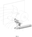
FIG. 4 is a schematic action view of the reel changing and automatic belt receiving mechanism after the reel is changed into place according to an embodiment of the present application. - The concept, specific structure and technical effects of the present application will be described clearly and in details with reference to embodiments and accompanying drawings, so as to fully understand the purpose, features and effects of the present application. Obviously, the embodiments described are only part of the present application, not all embodiments. Based on the embodiments of the present application, other embodiments obtained by those skilled in the art without creative efforts are within the scope of the present application. In addition, all the connections/connection relationships involved in the present application do not refer to the direct connection of components, but to the addition or reduction of connection accessories according to the specific implementation to form a better connection structure. The various technical features of the present application can be combined interactively without conflicting with each other, as shown in
FIGS. 1-4 . - Referring to
FIG. 1 , the present application provides: - A reel changing and belt receiving module, including a
horizontal moving assembly 1. In this embodiment, thehorizontal moving assembly 1 includes a horizontal moving guide rail and a horizontal moving drivenmotor 101, and the horizontal moving drivenmotor 101 is a power source of thehorizontal moving assembly 1. In other embodiments, according to different implementation environments, a moving assembly that meets the motion requirements, such as a horizontal electric cylinder, an oil cylinder, or a pneumatic cylinder, can be selected as the horizontal moving assembly. - The output end of the
horizontal moving assembly 1 is directly or indirectly provided with a forward and backward movingassembly 3, and the moving direction of thehorizontal moving assembly 1 is perpendicular to the forward and backward direction of the forward and backward movingassembly 3. The output end of the forward and backward movingassembly 3 is provided with abelt receiving roller 41 and a belt receiving roller drivenassembly 42. In this embodiment, the output end of thehorizontal moving assembly 1 is provided with aswing adjustment assembly 2, specifically, the output end of thehorizontal moving assembly 1 is provided with a horizontalmoving installation seat 11, and theswing adjustment assembly 2 is fixedly installed on the horizontalmoving installation seat 11. The output end of theswing adjustment assembly 2 is provided with a forward and backward movingassembly 3. Theswing adjustment assembly 2 includes a swing drivenmotor 21, a swing reducer provided at the output end of the swing drivenmotor 21, and aswing installation plate 22 provided on the output shaft of the swing reducer. The forward and backward movingassembly 3 is fixedly installed on theswing installation plate 22, the swing drivenmotor 21 can drive theswing installation plate 22 to swing through the swing reducer and further drive the forward and backward movingassembly 3 to swing through theswing installation plate 22. - The output end of the forward and backward moving
assembly 3 is provided with a belt receivingroller installation seat 4. In this embodiment, the forward and backward movingassembly 3 is a pneumatic moving assembly, the output end of the forward and backward movingassembly 3 is provided with a forward and backward movinginstallation plate 31, and the belt receivingroller installation seat 4 is fixedly installed on the forward and backward movinginstallation plate 31. The forward and backward movingassembly 3 is configured to drive the belt receivingroller installation seat 4 and other components fixed on the belt receivingroller installation seat 4 to move forward and backward. The belt receivingroller installation seat 4 is provided with abelt receiving roller 41 and a belt receiving roller drivenassembly 42. Thebelt receiving roller 41 is provided with acutter assembly 43. Thecutter assembly 43 includes acutter installation seat 431 fixedly installed on the installation shaft of thebelt receiving roller 41, a cutter installation plate fixed on thecutter installation seat 431, and asawtooth cutter 432 fixedly installed on the cutter installation plate. The output end of the belt receiving roller drivenassembly 42 is connected to one end of thebelt receiving roller 41 and can drive thebelt receiving roller 41 to rotate. The rotatingbelt receiving roller 41 can drive thecutter assembly 43 to rotate around the central shaft of thebelt receiving roller 41 to cut the belt. - In an embodiment, a
cutter protection cover 44 that can rotate around the central shaft of thebelt receiving roller 41 is provided on the side of thebelt receiving roller 41, and a protection cover drivenassembly 45 is provided on the belt receivingroller installation seat 4. The protection cover drivenassembly 45 is configured to drive thecutter protection cover 44 to rotate around the central shaft of thebelt receiving roller 41. The protection cover drivenassembly 45 includes a protection cover driven motor. The belt receiving roller drivenassembly 42 includes a belt receiving roller drivenmotor 421, a belt receivingroller reducer 422 provided at the output end of the belt receiving roller drivenmotor 421, and ashaft coupling 423 connected between the output end of the belt receivingroller reducer 422 and one end of the rotation shaft of thebelt receiving roller 41. - Further, a protection
cover installation plate 441 is rotatably provided on the rotation shaft of thebelt receiving roller 41, and thecutter protection cover 44 is installed on the protectioncover installation plate 441. A protectioncover transmission assembly 46 is provided between the output end of the protection cover drivenassembly 45 and one of the protectioncover installation plates 441, and the protection cover drivenassembly 45 can drive the protectioncover installation plate 441 and thecutter protection cover 44 to rotate through the protectioncover transmission assembly 46. The protectioncover transmission assembly 46 includes an active synchronization wheel provided at the output end of the protection cover drivenassembly 45, a driven synchronization wheel provided on one of the protectioncover installation plates 441, and a synchronization belt wound between the active synchronization wheel and the driven synchronization wheel. The protection cover drivenassembly 45 can drive the protectioncover installation plate 441 and thecutter protection cover 44 to rotate through the active synchronization wheel, the synchronization belt, and the driven synchronization wheel. - When the present application is specifically implemented, the horizontal moving
assembly 1 can drive thebelt receiving roller 41 to move horizontally to a suitable position, and theswing adjustment assembly 2 can drive thebelt receiving roller 41 to swing, so as to realize the position swing change of thebelt receiving roller 41 when changing reels. The forward and backward movingassembly 3 can drive thebelt receiving roller 41 to move forward and backward. Furthermore, the belt receiving roller drivenmotor 421 in the belt receiving roller drivenassembly 42 can drive thebelt receiving roller 41 to rotate through the belt receivingroller reducer 421 and theshaft coupling 423, and thebelt receiving roller 41 can drive thecutter assembly 43 to rotate, so that the material belt is cut by thesawtooth cutter 432 in thecutter assembly 43. - In order to protect the
cutter assembly 43 and prevent thecutter assembly 43 from switching between the working state and the idle state, acutter protection cover 44 and a protection cover drivenassembly 45 corresponding to thecutter protection cover 44 are provided. Specifically, the protection cover driven motor in the protection cover drivenassembly 45 drives thecutter protection cover 44 to rotate through the protectioncover transmission assembly 46. When thecutter assembly 43 is required to be cut, the protection cover drivenassembly 45 drives thecutter protection cover 44 to rotate to a position misaligned with thecutter assembly 43 through the protectioncover transmission assembly 46. At this time, thecutter assembly 42 can be configured to cut the material belt. When the material belt is cut by thecutter assembly 43, the protection cover drivenassembly 45 can be configured to drive thecutter protection cover 44 to rotate to a position covering thecutter assembly 43, so as to prevent thecutter assembly 43 from being damaged by other components or prevent thecutter assembly 43 from causing damage to the operator, thereby improving safety. - Specifically referring to
FIG. 2 ,FIG. 3 , andFIG. 4 , based on the above-mentioned reel changing and belt receiving module, the present application also provides a new solution, which is:
a reel changing and automatic belt receiving mechanism, including an installationmain plate 5, on which a rotation roller 6, afirst roller cylinder 71 and asecond roller cylinder 72 are provided, and the reel changing and automatic belt receiving mechanism also includes the reel changing and belt receiving module. Specifically, the rotation rollers 6 are provided in pairs and configured to convey the material belt product 9, and thefirst roller cylinder 71 and thesecond roller cylinder 72 are configured for rolling and cooperate for rolling work in different time periods. - Generally, in the reel changing and automatic belt receiving mechanism, the installation
main plate 5 is the main supporting component and plays the main supporting and installing role. At least one of the two rotation rollers 6 is an active roller. When the two rotation rollers 6 clamp the material belt product 9, the driven component (generally a motor) in the rotation roller 6 drives the rotation roller 6 to rotate, and the rotation roller 6 further drives the material belt to be transported forward. - In addition, the
first roller cylinder 71 and thesecond roller cylinder 72 are both active rolling cylinders, which have rolling power to realize the rolling action of the material belt product 9. In an embodiment, when the rolling power of the rolling cylinder is sufficient, without damaging the material belt product 9 and affecting the rolling efficiency, the two rotation rollers 6 can also be configured as driven rollers, and the rotation rollers 6 do not have a rotational force. - When this reel changing and automatic belt receiving mechanism is working, referring to
FIG. 3 , when one of the rolling cylinders reaches the reel changing status, under the joint action of the horizontal movingassembly 1, theswing adjustment assembly 2 and the forward and backward movingassembly 3, thebelt receiving roller 41 abutted against the right side of the material belt product 9. At this time, theswing adjustment assembly 2 moves the material belt product 9 to the preset initial position of the corresponding rollingcylinder 71 through thebelt receiving roller 41. During the swinging process of thebelt receiving roller 41, thecutter assembly 43 is covered and protected by thecutter protection cover 44. During this process, thecutter assembly 43 will not cut the material belt product 9. After thebelt receiving roller 41 moves to the designated position, referring toFIG. 4 , thebelt receiving roller 41 contacts the material belt product 9 and pulls the material belt product to the vicinity of the first roller cylinder 71 (empty cylinder) and finally makes the material belt product 9 fit to the emptyfirst roller cylinder 71. The material belt product 9 and the rolling barrel are combined in the following ways: bonding, adsorption, pressing, etc. - After the material belt product 9 is combined with the
first roller cylinder 71, the belt receiving roller drivenassembly 42 drives thebelt receiving roller 41 and thecutter assembly 43 to rotate and cut the material belt product 9. After the material belt product 9 is cut, thebelt receiving roller 41 is retracted by the forward and backward movingassembly 3, and the entire reel changing and belt receiving module is reset by the horizontal movingassembly 1 and theswing adjustment assembly 2. At this time, thefirst roller cylinder 71 can realize automatic rolling, and thesecond roller cylinder 72 can unload the full material roll. - Similarly, when the
first roller cylinder 71 is full of material, the above-mentioned actions are repeated to automatically switch between thefirst roller cylinder 71 and thesecond roller cylinder 72 without stopping the machine, which can realize full automation, reduce labor costs, save time and improve production efficiency. - Based on the reel changing and belt receiving module, and the reel changing and automatic belt receiving mechanism, the present application also provides:
- A winding device including the above-mentioned reel changing and belt receiving module or the above-mentioned reel changing and automatic belt receiving mechanism.
- Based on the above-mentioned reel changing and belt receiving module, the reel changing and automatic belt receiving mechanism, and the winding device, the present application also provides:
A production line, the device of the production line includes the above-mentioned reel changing and belt receiving module, or the device of the production line includes the above-mentioned reel changing and automatic belt receiving mechanism, or the production line adopts the above-mentioned winding device. - The embodiments of the present application are described in details above, but the present application is not limited to the embodiments. Those skilled in the art can also make a variety of equivalent variations or substitutions without deviating from the spirit of the present application, and such equivalent variations or substitutions are contained in the scope of the claims of the present application.
Claims (11)
- A reel changing and belt receiving module, characterized by comprising:a horizontal moving assembly;wherein an output end of the horizontal moving assembly is provided with a forward and backward moving assembly, and a moving direction of the horizontal moving assembly is perpendicular to a forward and backward direction of the forward and backward moving assembly; an output end of the forward and backward moving assembly is provided with a belt receiving roller and a belt receiving roller driven assembly, and a cutter assembly is provided on the belt receiving roller; an output end of the belt receiving roller driven assembly is connected to one end of the belt receiving roller and is configured to drive the belt receiving roller to rotate, and the rotating belt receiving roller is configured to drive the cutter assembly to rotate around a central shaft of the belt receiving roller to cut a belt;a cutter protection cover configured to rotate around the central shaft of the belt receiving roller is provided on a side of the belt receiving roller; a protection cover driven assembly is provided on an installation seat at one end of the belt receiving roller, and the protection cover driven assembly is configured to drive the cutter protection cover to rotate around the central shaft of the belt receiving roller;the protection cover driven assembly comprises a protection cover driven motor, and the belt receiving roller driven assembly comprises a belt receiving roller driven motor, a belt receiving roller reducer provided at an output end of the belt receiving roller driven motor, and a shaft coupling connected between an output end of the belt receiving roller reducer and one end of a rotation shaft of the belt receiving roller;a protection cover installation plate is rotatably provided on the rotation shaft of the belt receiving roller, and the cutter protection cover is installed on the protection cover installation plate; a protection cover transmission assembly is provided between an output end of the protection cover driven assembly and one of the protection cover installation plates, and the protection cover driven assembly is configured to drive the protection cover installation plate and the cutter protection cover to rotate through the protection cover transmission assembly; andthe output end of the horizontal moving assembly is provided with a swing adjustment assembly, and the forward and backward moving assembly is provided at an output end of the swing adjustment assembly.
- The reel changing and belt receiving module according to claim 1, wherein the protection cover transmission assembly comprises an active synchronization wheel provided at the output end of the protection cover driven assembly, a driven synchronization wheel provided on one of the protection cover installation plates, and a synchronization belt wound between the active synchronization wheel and the driven synchronization wheel; and
the protection cover driven assembly is configured to drive the protection cover installation plate and the cutter protection cover to rotate through the active synchronization wheel, the synchronization belt, and the driven synchronization wheel. - The reel changing and belt receiving module according to claim 1, wherein the cutter assembly comprises a cutter installation seat fixedly installed on the installation shaft of the belt receiving roller, a cutter installation plate fixed on the cutter installation seat, and a sawtooth cutter fixedly installed on the cutter installation plate.
- The reel changing and belt receiving module according to claim 1, wherein the output end of the horizontal moving assembly is provided with a horizontal moving installation seat, and the forward and backward moving assembly is directly or indirectly installed on the horizontal moving installation seat.
- The reel changing and belt receiving module according to claim 1, wherein the swing adjustment assembly comprises a swing driven motor, a swing reducer provided at an output end of the swing driven motor, and a swing installation plate provided on an output shaft of the swing reducer; and
the forward and backward moving assembly is fixedly installed on the swing installation plate, and the swing driven motor is configured to drive the swing installation plate to swing through the swing reducer and further drive the forward and backward moving assembly to swing through the swing installation plate. - The reel changing and belt receiving module according to claim 1, wherein the output end of the forward and backward moving assembly is provided with a belt receiving roller installation seat, and the belt receiving roller and the belt receiving roller driven assembly are installed on the belt receiving roller installation seat.
- The reel changing and belt receiving module according to claim 1, wherein the horizontal moving assembly comprises a horizontal moving guide rail and a horizontal moving driven motor; the forward and backward moving assembly is a pneumatic moving assembly, and the output end of the forward and backward moving assembly is provided with a forward and backward moving installation plate.
- A reel changing and automatic belt receiving mechanism, characterized by comprising:an installation main plate; andthe reel changing and belt receiving module in any one of claims 1 to 7;wherein a rotation roller, a first roller cylinder and a second roller cylinder are provided on the installation main plate.
- The reel changing and automatic belt receiving mechanism according to claim 8, wherein pairs of rotation rollers are provided to convey material belt products, and the first roller cylinder and the second roller cylinder are configured for rolling and cooperating for rolling work in different time periods.
- A winding device, characterized by comprising:the reel changing and belt receiving module in any one of claims 1 to 7; orthe reel changing and automatic belt receiving mechanism in any one of claims 8 to 9.
- A production line, characterized in that a device of the production line comprises the reel changing and belt receiving module in any one of claims 1 to 7, or the device of the production line comprises the reel changing and automatic belt receiving mechanism in any one of claims 8 to 9, or the production line adopts the winding device in claim 10.
Applications Claiming Priority (2)
| Application Number | Priority Date | Filing Date | Title |
|---|---|---|---|
| CN202210833402.4A CN115196390B (en) | 2022-07-14 | 2022-07-14 | Reel-changing and tape-connecting module, reel-changing automatic tape-connecting mechanism, winding equipment and production line |
| PCT/CN2023/118617 WO2024012606A1 (en) | 2022-07-14 | 2023-09-13 | Winding switching and strip receiving module, winding switching and automatic strip receiving mechanism, winding device, and production line |
Publications (2)
| Publication Number | Publication Date |
|---|---|
| EP4450435A1 true EP4450435A1 (en) | 2024-10-23 |
| EP4450435A4 EP4450435A4 (en) | 2025-10-29 |
Family
ID=83581530
Family Applications (1)
| Application Number | Title | Priority Date | Filing Date |
|---|---|---|---|
| EP23839090.0A Pending EP4450435A4 (en) | 2022-07-14 | 2023-09-13 | Winding switch and tape recording module, winding switch and automatic tape recording, winding device and production line |
Country Status (5)
| Country | Link |
|---|---|
| US (1) | US20250122042A1 (en) |
| EP (1) | EP4450435A4 (en) |
| KR (1) | KR20250039923A (en) |
| CN (1) | CN115196390B (en) |
| WO (1) | WO2024012606A1 (en) |
Families Citing this family (5)
| Publication number | Priority date | Publication date | Assignee | Title |
|---|---|---|---|---|
| CN115196390B (en) * | 2022-07-14 | 2023-09-12 | 海目星激光科技集团股份有限公司 | Reel-changing and tape-connecting module, reel-changing automatic tape-connecting mechanism, winding equipment and production line |
| CN115724251B (en) * | 2022-12-19 | 2025-12-12 | 苏州巨一智能装备有限公司 | An electrode unwinding mechanism |
| CN117208624A (en) * | 2023-10-10 | 2023-12-12 | 广东省秦田科技有限公司 | Composite tape splicing and reel changing mechanism and tape splicing and reel changing method |
| CN119898649B (en) * | 2023-10-26 | 2026-01-13 | 宁德时代新能源科技股份有限公司 | Roll changing equipment and method for battery material belt and die cutting machine |
| CN117429908B (en) * | 2023-10-31 | 2026-01-27 | 三一技术装备有限公司 | Unreeling device for material belt and battery production line |
Family Cites Families (14)
| Publication number | Priority date | Publication date | Assignee | Title |
|---|---|---|---|---|
| NL285406A (en) * | 1962-11-13 | |||
| DE102008033736A1 (en) * | 2008-07-18 | 2010-01-21 | Windmöller & Hölscher Kg | Device and method for winding and / or unwinding webs of material |
| CN202046737U (en) * | 2011-01-18 | 2011-11-23 | 福清市友谊胶粘带制品有限公司 | Automatic cutting device of adhesive-tape non-stopping winding machine |
| CN202464863U (en) * | 2012-02-11 | 2012-10-03 | 广东仕诚塑料机械有限公司 | Chopper device for cast film winding machine |
| CN202944918U (en) * | 2012-11-28 | 2013-05-22 | 泉州市丰泽区东方机械有限公司 | Thin film reeling and cutting off device |
| CN205204375U (en) * | 2015-12-16 | 2016-05-04 | 灵璧腾利科技发展有限公司 | Automatic reel alternation device of sticky tape rolling machine |
| CN205325785U (en) * | 2016-01-13 | 2016-06-22 | 嘉兴市丰莱桑达贝纸业有限公司 | Rewinding paper cutter |
| CN207361451U (en) * | 2017-10-16 | 2018-05-15 | 厦门金汇峰新型包装材料股份有限公司 | Film change of lap disconnecting device |
| CN208279047U (en) * | 2018-03-29 | 2018-12-25 | 汕头市远东轻化装备有限公司 | Convertible film take-up roll changing apparatus |
| CN212197741U (en) * | 2019-12-24 | 2020-12-22 | 无锡先导智能装备股份有限公司 | Tape splicing mechanism, automatic roll changing device and winding equipment |
| CN114300757B (en) * | 2021-12-31 | 2024-04-19 | 深圳吉阳智能科技有限公司 | Automatic reel changing and tape connecting mechanism |
| CN114516560B (en) * | 2022-03-14 | 2023-11-24 | 惠州市新鑫辉自动化设备有限公司 | Automatic roll changing device |
| CN114620515A (en) * | 2022-03-25 | 2022-06-14 | 深圳市海目星激光智能装备股份有限公司 | Automatic roll changing device, method and application thereof |
| CN115196390B (en) * | 2022-07-14 | 2023-09-12 | 海目星激光科技集团股份有限公司 | Reel-changing and tape-connecting module, reel-changing automatic tape-connecting mechanism, winding equipment and production line |
-
2022
- 2022-07-14 CN CN202210833402.4A patent/CN115196390B/en active Active
-
2023
- 2023-09-13 WO PCT/CN2023/118617 patent/WO2024012606A1/en not_active Ceased
- 2023-09-13 KR KR1020247024785A patent/KR20250039923A/en active Pending
- 2023-09-13 US US18/728,764 patent/US20250122042A1/en active Pending
- 2023-09-13 EP EP23839090.0A patent/EP4450435A4/en active Pending
Also Published As
| Publication number | Publication date |
|---|---|
| CN115196390B (en) | 2023-09-12 |
| KR20250039923A (en) | 2025-03-21 |
| CN115196390A (en) | 2022-10-18 |
| WO2024012606A1 (en) | 2024-01-18 |
| US20250122042A1 (en) | 2025-04-17 |
| EP4450435A4 (en) | 2025-10-29 |
Similar Documents
| Publication | Publication Date | Title |
|---|---|---|
| EP4450435A1 (en) | Winding switching and strip receiving module, winding switching and automatic strip receiving mechanism, winding device, and production line | |
| CN208008129U (en) | A kind of pole piece automatic coiling and roll-switching device | |
| CN207792220U (en) | A kind of automatic splicing equipment | |
| CN117208624A (en) | Composite tape splicing and reel changing mechanism and tape splicing and reel changing method | |
| CN202259550U (en) | Semi-automatic winding machine for battery roll core | |
| CN218612335U (en) | Cutting device for laser cutting of tab | |
| CN115339932A (en) | Slitting equipment | |
| CN219156009U (en) | Non-stop shaft replacing device of splitting machine | |
| CN119873465A (en) | Winding and unwinding mechanism and winding and unwinding integrated device | |
| CN220537044U (en) | Biax coiling mechanism and paster equipment | |
| CN218311251U (en) | Lifting type cantilever cutter device and winding and unwinding tape splicing equipment | |
| CN216763655U (en) | Automatic connection unwinding mechanism | |
| CN211034551U (en) | Saw blade back-rolling device | |
| CN118522968A (en) | Winding machine | |
| CN223607616U (en) | Cloth roll cutting auxiliary device | |
| CN210795271U (en) | Coating and folding cut-off conveyer | |
| CN221583693U (en) | Base film cutting tool and system for base film circulation feeding mechanism | |
| CN223509334U (en) | Film winding device and film winding system | |
| CN220684182U (en) | Automatic film receiving device of film laminating machine | |
| CN219521198U (en) | Pole piece processing device and equipment | |
| CN223879106U (en) | Winding and unwinding mechanism and winding and unwinding integrated device | |
| CN220998617U (en) | Terminal conveying stroke confirmation structure | |
| CN118753883B (en) | High-speed material area winding and unwinding device | |
| CN223245664U (en) | Automatic unwinding and splicing device | |
| CN223046886U (en) | Film winding machine based on pneumatic shaft |
Legal Events
| Date | Code | Title | Description |
|---|---|---|---|
| STAA | Information on the status of an ep patent application or granted ep patent |
Free format text: STATUS: THE INTERNATIONAL PUBLICATION HAS BEEN MADE |
|
| PUAI | Public reference made under article 153(3) epc to a published international application that has entered the european phase |
Free format text: ORIGINAL CODE: 0009012 |
|
| STAA | Information on the status of an ep patent application or granted ep patent |
Free format text: STATUS: REQUEST FOR EXAMINATION WAS MADE |
|
| 17P | Request for examination filed |
Effective date: 20240715 |
|
| AK | Designated contracting states |
Kind code of ref document: A1 Designated state(s): AL AT BE BG CH CY CZ DE DK EE ES FI FR GB GR HR HU IE IS IT LI LT LU LV MC ME MK MT NL NO PL PT RO RS SE SI SK SM TR |
|
| XX | Miscellaneous (additional remarks) |
Free format text: A REQUEST FOR RESTORATION OF THE RIGHT OF PRIORITY UNDER RULE 49TER.2 PCT IS PENDING BEFORE THE EPO AS DESIGNATED OFFICE |
|
| A4 | Supplementary search report drawn up and despatched |
Effective date: 20250930 |
|
| RIC1 | Information provided on ipc code assigned before grant |
Ipc: B65H 19/18 20060101AFI20250924BHEP Ipc: H01M 10/04 20060101ALI20250924BHEP Ipc: B65H 19/20 20060101ALI20250924BHEP |