EP4450428A1 - Workpiece transport method and workpiece transport device - Google Patents
Workpiece transport method and workpiece transport device Download PDFInfo
- Publication number
- EP4450428A1 EP4450428A1 EP22907239.2A EP22907239A EP4450428A1 EP 4450428 A1 EP4450428 A1 EP 4450428A1 EP 22907239 A EP22907239 A EP 22907239A EP 4450428 A1 EP4450428 A1 EP 4450428A1
- Authority
- EP
- European Patent Office
- Prior art keywords
- workpieces
- inspection
- workpiece
- inspection section
- transport
- Prior art date
- Legal status (The legal status is an assumption and is not a legal conclusion. Google has not performed a legal analysis and makes no representation as to the accuracy of the status listed.)
- Pending
Links
Images

Classifications
-
- G—PHYSICS
- G01—MEASURING; TESTING
- G01N—INVESTIGATING OR ANALYSING MATERIALS BY DETERMINING THEIR CHEMICAL OR PHYSICAL PROPERTIES
- G01N21/00—Investigating or analysing materials by the use of optical means, i.e. using sub-millimetre waves, infrared, visible or ultraviolet light
- G01N21/84—Systems specially adapted for particular applications
- G01N21/88—Investigating the presence of flaws or contamination
- G01N21/90—Investigating the presence of flaws or contamination in a container or its contents
- G01N21/9009—Non-optical constructional details affecting optical inspection, e.g. cleaning mechanisms for optical parts, vibration reduction
-
- B—PERFORMING OPERATIONS; TRANSPORTING
- B65—CONVEYING; PACKING; STORING; HANDLING THIN OR FILAMENTARY MATERIAL
- B65G—TRANSPORT OR STORAGE DEVICES, e.g. CONVEYORS FOR LOADING OR TIPPING, SHOP CONVEYOR SYSTEMS OR PNEUMATIC TUBE CONVEYORS
- B65G17/00—Conveyors having an endless traction element, e.g. a chain, transmitting movement to a continuous or substantially-continuous load-carrying surface or to a series of individual load-carriers; Endless-chain conveyors in which the chains form the load-carrying surface
- B65G17/24—Conveyors having an endless traction element, e.g. a chain, transmitting movement to a continuous or substantially-continuous load-carrying surface or to a series of individual load-carriers; Endless-chain conveyors in which the chains form the load-carrying surface comprising a series of rollers which are moved, e.g. over a supporting surface, by the traction element to effect conveyance of loads or load-carriers
-
- B—PERFORMING OPERATIONS; TRANSPORTING
- B65—CONVEYING; PACKING; STORING; HANDLING THIN OR FILAMENTARY MATERIAL
- B65G—TRANSPORT OR STORAGE DEVICES, e.g. CONVEYORS FOR LOADING OR TIPPING, SHOP CONVEYOR SYSTEMS OR PNEUMATIC TUBE CONVEYORS
- B65G25/00—Conveyors comprising a cyclically-moving, e.g. reciprocating, carrier or impeller which is disengaged from the load during the return part of its movement
- B65G25/02—Conveyors comprising a cyclically-moving, e.g. reciprocating, carrier or impeller which is disengaged from the load during the return part of its movement the carrier or impeller having different forward and return paths of movement, e.g. walking beam conveyors
-
- B—PERFORMING OPERATIONS; TRANSPORTING
- B65—CONVEYING; PACKING; STORING; HANDLING THIN OR FILAMENTARY MATERIAL
- B65G—TRANSPORT OR STORAGE DEVICES, e.g. CONVEYORS FOR LOADING OR TIPPING, SHOP CONVEYOR SYSTEMS OR PNEUMATIC TUBE CONVEYORS
- B65G43/00—Control devices, e.g. for safety, warning or fault-correcting
-
- B—PERFORMING OPERATIONS; TRANSPORTING
- B65—CONVEYING; PACKING; STORING; HANDLING THIN OR FILAMENTARY MATERIAL
- B65G—TRANSPORT OR STORAGE DEVICES, e.g. CONVEYORS FOR LOADING OR TIPPING, SHOP CONVEYOR SYSTEMS OR PNEUMATIC TUBE CONVEYORS
- B65G43/00—Control devices, e.g. for safety, warning or fault-correcting
- B65G43/08—Control devices operated by article or material being fed, conveyed or discharged
-
- B—PERFORMING OPERATIONS; TRANSPORTING
- B65—CONVEYING; PACKING; STORING; HANDLING THIN OR FILAMENTARY MATERIAL
- B65G—TRANSPORT OR STORAGE DEVICES, e.g. CONVEYORS FOR LOADING OR TIPPING, SHOP CONVEYOR SYSTEMS OR PNEUMATIC TUBE CONVEYORS
- B65G43/00—Control devices, e.g. for safety, warning or fault-correcting
- B65G43/10—Sequence control of conveyors operating in combination
-
- B—PERFORMING OPERATIONS; TRANSPORTING
- B65—CONVEYING; PACKING; STORING; HANDLING THIN OR FILAMENTARY MATERIAL
- B65G—TRANSPORT OR STORAGE DEVICES, e.g. CONVEYORS FOR LOADING OR TIPPING, SHOP CONVEYOR SYSTEMS OR PNEUMATIC TUBE CONVEYORS
- B65G47/00—Article or material-handling devices associated with conveyors; Methods employing such devices
- B65G47/52—Devices for transferring articles or materials between conveyors i.e. discharging or feeding devices
- B65G47/66—Fixed platforms or combs, e.g. bridges between conveyors
-
- G—PHYSICS
- G01—MEASURING; TESTING
- G01N—INVESTIGATING OR ANALYSING MATERIALS BY DETERMINING THEIR CHEMICAL OR PHYSICAL PROPERTIES
- G01N21/00—Investigating or analysing materials by the use of optical means, i.e. using sub-millimetre waves, infrared, visible or ultraviolet light
- G01N21/84—Systems specially adapted for particular applications
- G01N21/88—Investigating the presence of flaws or contamination
- G01N21/95—Investigating the presence of flaws or contamination characterised by the material or shape of the object to be examined
- G01N21/958—Inspecting transparent materials or objects, e.g. windscreens
Definitions
- the present invention relates to a workpiece transport method and a workpiece transport apparatus.
- Patent Literature 1 discloses an example of a workpiece transport apparatus that transports workpieces along an arc-shaped transport path.
- Patent Literature 1 Japanese Laid-Open Patent Publication No. 2018-017547
- An object of the present invention is to provide a workpiece transport method and a workpiece transport apparatus that improve the workpiece inspection accuracy.
- a method for transporting workpieces that solves the above problem includes an inspection section transporting step of transporting the workpieces in an inspection section, where the workpieces are inspected, with an inspection section transport device.
- the inspection section transporting step includes decreasing a transport speed of the workpieces at an inspection position where the workpieces are inspected or temporarily stopping transportation of the workpieces at the inspection position.
- the above method for transporting workpieces may further include a loading step of continuously loading the workpieces to the inspection section with a conveyor device.
- the transport speed of the workpieces to the inspection position may be higher than a loading speed of the workpieces in the loading step.
- the conveyor device and the inspection section transport device may each include supports that support the workpieces.
- the intervals between the supports of the conveyor device may be smaller than the intervals between the supports of the inspection section transport device.
- the inspection section transport device may include a holding unit arranged in correspondence with the inspection position to hold the workpieces, and a workpiece carrier that loads the workpieces to the holding unit and unloads the workpieces from the holding unit.
- transportation of the workpieces may be temporarily stopped at the inspection position.
- the workpiece carrier may include a carrier support member that supports the workpieces.
- the carrier support member may be moved by a parallel crank mechanism.
- the inspection section transporting step may include a stopping phase in which actuation of the parallel crank mechanism is stopped.
- the inspection section transport device may transport the workpieces along an arc-shaped transport path.
- each of the workpieces may have an elongated shape and may be transported such that a longitudinal direction of the workpieces is orthogonal to a transport direction.
- a workpiece transport apparatus includes an inspection section transport device that transports workpieces in an inspection section where the workpieces are inspected.
- the inspection section transport device decreases a transport speed of the workpieces at an inspection position where the workpieces are inspected or temporarily stops transportation of the workpieces at the inspection position.
- the present invention enables improvement of the accuracy in inspecting the workpieces.
- a workpiece transport apparatus 11 includes an inspection section 12 where workpieces W are inspected and a first conveyor device 13 that transports the workpieces W to the inspection section 12.
- the workpiece transport apparatus 11 further includes an inspection section transport device 14 that transports the workpieces W in the inspection section 12.
- the workpiece transport apparatus 11 of the present embodiment further includes a second conveyor device 15 that transports the workpieces W unloaded from the inspection section 12.
- the workpiece transport apparatus 11 further includes a controller 16.
- each workpiece W of the present embodiment has an elongated shape and includes a first end Wa and a second end Wb in a longitudinal direction.
- the workpiece transport apparatus 11 transports the workpieces W such that the longitudinal direction of each workpiece W is orthogonal to a transport direction in plan view.
- the workpiece W of the present embodiment is a glass tube.
- the workpiece transport apparatus 11 transports the glass tubes such that the tube-axis direction of each glass tube is orthogonal to the transport direction.
- the X-direction shown in the drawings corresponds to the transport direction.
- the Y-direction shown in the drawing corresponds to the longitudinal direction of the workpiece W, or a direction parallel to the tube axis of the glass tube.
- the Z-direction corresponds to the vertical direction.
- the inspection section 12 of the present embodiment includes a first image capturing device 12a, a second image capturing device 12b, and a third image capturing device 12c.
- the first image capturing device 12a, the second image capturing device 12b, and the third image capturing device 12c are arranged in this order from an upstream side with respect to the transport direction of the workpieces W.
- the workpieces W are inspected at predetermined inspection positions in the inspection section 12.
- the workpiece W located at a first inspection position P1 is imaged by the first image capturing device 12a.
- the workpiece W located at a second inspection position P2 is imaged by the second image capturing device 12b.
- the workpiece W located at a third inspection position P3 is imaged by the third image capturing device 12c.
- the first image capturing device 12a, the second image capturing device 12b, and the third image capturing device 12c capture images of the workpieces W for inspection.
- the workpieces W are inspected for end-shape defects, cleanliness, and the like.
- the image capturing device may be, for example, a camera including an image capturing element such as CCD or CMOS.
- the inspection section 12 may include, for example, a lighting device arranged facing the image capturing device.
- the first conveyor device 13 of the workpiece transport apparatus 11 is arranged at the upstream side of the inspection section 12.
- the first conveyor device 13 includes two first conveyor devices 13 respectively provided for the first end Wa and the second end Wb of the workpiece W.
- each first conveyor device 13 includes an endless first belt 13a and first supports 13b arranged on the first belt 13a.
- the two first conveyor devices 13 transport the workpieces W such that the longitudinal direction of each workpiece W is orthogonal to the transport direction of the workpieces W in plan view.
- the first conveyor devices 13 of the present embodiment continuously transport the workpieces W to the inspection section 12 at a fixed speed.
- the inspection section transport device 14 of the workpiece transport apparatus 11 includes two inspection section transport devices 14 respectively provided for the first end Wa and the second end Wb of the workpiece W.
- the inspection section transport devices 14 of the workpiece transport apparatus 11 temporarily stop transportation of the workpieces W at the first inspection position P1, the second inspection position P2, and the third inspection position P3. Further, the inspection section transport devices 14 transport the workpieces W to the first inspection position P1 at a higher transport speed than a loading speed at which the first conveyor device 13 transport the workpieces W to the inspection section 12.
- the inspection section transport device 14 of the present embodiment includes a holding unit 17 and a workpiece carrier 18.
- the holding unit 17 holds the workpieces W.
- the workpiece carrier 18 loads the workpieces W to the holding unit 17 and unloads the workpieces Wfrom the holding unit 17.
- the holding unit 17 includes a first holding portion 17a and a second holding portion 17b arranged at the downstream side of the first holding portion 17a.
- the second holding portion 17b is arranged in correspondence with the inspection positions where the workpieces W are inspected.
- the first holding portion 17a holds one or more workpieces W in a state in which the workpieces W are stationary.
- the second holding portion 17b includes a rolling mechanism that rolls the workpieces W at the inspection positions. More specifically, the second holding portion 17b includes rotary bodies, and each workpiece W is held and rotated by two adjacent ones of the rotary bodies about the axis of the workpiece W.
- the glass tube which is the workpiece W in the present embodiment, is rotated about the tube axis.
- the workpiece carrier 18 includes a carrier support member 18a that supports the workpieces W.
- the carrier support member 18a is moved by a parallel crank mechanism.
- the workpiece carrier 18 includes two rotation shafts 18b and a drive unit 18c.
- the drive unit 18c drives and rotates at least one of the two rotation shafts 18b.
- the workpiece carrier 18 includes two arms 18d and two coupling portions 18e. The two arms 18d are rotated by the two rotation shafts 18b.
- the two coupling portions 18e rotatably couple the arms 18d and the carrier support member 18a.
- the inspection section transport device 14 transports the workpieces W in the inspection section 12 by actuation of the parallel crank mechanism.
- the inspection section transport device 14 has a stopping phase in which the actuation of the parallel crank mechanism is stopped during transporting the workpieces W.
- the carrier support member 18a of the workpiece carrier 18 is configured to support more than one workpiece W. More specifically, as shown in Figs. 1 and 2 , the carrier support member 18a includes carrier supports 19 that support the workpieces W. Further, the second holding portion 17b is configured to hold the workpieces W at the inspection positions, such as the first inspection position P1, the second inspection position P2, and the like. In the present embodiment, the distances between the carrier supports 19, the distances between the workpieces W held by the first holding portion 17a, and the distances between the workpieces W held by the second holding portion 17b are set to align with the distances between the first inspection position P1, the second inspection position P2, and the third inspection position P3.
- the intervals between the first supports 13b of the first conveyor device 13 are smaller than the intervals between the carrier supports 19 of the carrier support member 18a.
- the second conveyor device 15 of the workpiece transport apparatus 11 is arranged at the downstream side of the inspection section 12.
- the second conveyor device 15 transports the workpieces W unloaded from the inspection section transport device 14.
- the second conveyor device 15 includes two second conveyor devices 15 respectively provided for the first end Wa and the second end Wb of the workpiece W.
- each second conveyor device 15 includes an endless second belt 15a and second supports 15b arranged on the second belt 15a. The two second conveyor devices 15 transport the workpieces W such that the longitudinal direction of each workpiece W is orthogonal to the transport direction of the workpiece W in plan view.
- the second conveyor devices 15 of the present embodiment transport the workpieces W that underwent inspection in the inspection section 12 to a sorting device 20.
- the sorting device 20 includes a sorting mechanism that separates defective glass tubes from the transport path of non-defective glass tubes.
- the controller 16 determines whether each workpiece W is anomalous based on images obtained by the first image capturing device 12a, the second image capturing device 12b, and the third image capturing device 12c.
- the first image capturing device 12a, the second image capturing device 12b, and the third image capturing device 12c obtain images of, for example, an end of the workpiece W, the outer circumferential surface of the workpiece W, and the like.
- the controller 16 includes, for example, an image processor, memory, and the like.
- the image processor may be configured to perform image processing, such as binary processing, brightness correction, and the like, on images including the workpiece Was necessary.
- the memory may store in advance images of a normal workpiece W, a brightness threshold value, and the like.
- the controller 16 may include a processor, memory, software, an image display device, and the like (not shown).
- the controller 16 may determine the state of each workpiece W, for example, by comparing a threshold value that is obtained from images of a normal workpiece W stored in the memory in advance with a value that is obtained from actual images captured by the image processor.
- the controller 16 may use a learning model that is constructed through deep learning in determining whether the workpiece W is anomalous.
- the learning model is an artificial intelligence (Al) model such as a neural network model. Based on the determination result of the controller 16, the sorting device 20 separates defective workpiece from non-defective workpieces.
- the second holding portion 17b is arranged, for example, at the first inspection position P1 to hold the workpiece W at a predetermined position.
- the workpiece W can also be inspected at the second inspection position P2 and the third inspection position P3 in a state in which transportation of the workpiece W is temporarily stopped.
- the workpiece carrier 18 carries the workpiece W again such that inspection is sequentially performed at the second inspection position P2 and the third inspection position P3.
- the method for transporting the workpieces W allows the workpieces W to be inspected at a high degree of accuracy in a state in which transportation of the workpieces W is temporarily stopped, for example, at the first inspection position P1. This improves the accuracy in inspecting the workpieces W.
- the transport speed of the workpieces W to the first inspection position P1 where the workpieces Ware inspected is higher than a loading speed of the workpieces W in the loading step.
- a loading speed of the workpieces W in the loading step even when the workpieces Ware transported in above-described inspection section transporting step, it is possible to maintain the loading speed of the workpieces W in the loading step at a predetermined speed or higher.
- the transport speed of the workpieces W to the first inspection position P1 is further increased in the inspection section transporting step, for example, the workpieces W can be stopped at the first inspection position P1 for a longer period.
- the parallel crank mechanism moves the carrier support member 18a.
- the inspection section transporting step includes a stopping phase in which actuation of the parallel crank mechanism is stopped.
- the timing of the operation of the workpiece carrier 18 is readily adjusted. For example, the period during which transportation of the workpieces W is temporarily stopped at the first inspection position P1 is readily adjusted.
- the intervals between the first supports 13b of the first conveyor device 13 are smaller than the intervals between the carrier supports 19 of the inspection section transport device 14.
- the number of first supports 13b and the number of carrier supports 19 are each three or more, preferably four or more, and further preferably, five or more.
- the inspection section transport device 14 includes the second holding portion 17b and the workpiece carrier 18.
- the second holding portion 17b holds the workpieces W transported by the workpiece carrier 18 so that transportation of the workpieces W is readily stopped, for example, at the first inspection position P1.
- the workpiece carrier 18 includes the carrier support member 18a that supports the workpieces W.
- the carrier support member 18a is moved by the parallel crank mechanism.
- the workpieces W are transported with a relatively simple structure.
- the inspection section transporting step includes a stopping phase in which the actuation of the parallel crank mechanism of the workpiece carrier 18 is stopped.
- the timing of the operation of the workpiece carrier 18 is readily adjusted. For example, the period during which transportation of the workpieces W is temporarily stopped at the first inspection position P1 is readily adjusted.
- each workpiece W has an elongated shape and is transported such that the longitudinal direction of the workpiece W is orthogonal to the transport direction. This enables improvement of the accuracy in inspecting such elongated workpieces W.
- the carrier support member 18a of the workpiece carrier 18 is configured to support more than one workpiece W.
- the second holding portion 17b is configured to hold the workpiece W at each of the inspection positions (such as the first inspection position P1 and the second inspection position P2). In this case, for example, more than one workpiece W can be simultaneously inspected in the inspection section 12. Also, multiple types of inspections may be performed on each workpiece W.
- the second holding portion 17b of the inspection section transport device 14 includes, for example, the roll mechanism that rolls the workpieces W at the first inspection position P1. In this case, inspection is readily performed along the outer circumference of the workpiece W.
- a workpiece transport apparatus 11 and a method for transporting workpieces W in accordance with a second embodiment will now be described focusing on differences from the first embodiment.
- the workpiece transport apparatus 11 of the second embodiment includes a third conveyor device 21 that loads the workpieces W to the inspection section 12 and unloads the workpieces W from the inspection section 12.
- the third conveyor device 21 includes an endless third belt 21a and third supports 21b arranged on the third belt 21a.
- the workpiece transport apparatus 11 includes an inspection section transport device 22.
- the inspection section transport device 22 includes a rotation mechanism that transports the workpieces W along an arc-shaped transport path.
- the inspection section transport device 22 includes rollers 23 that support the workpieces W such that each workpiece W is rotatable about the axis of the workpieces W.
- Each workpiece W is supported by a support portion formed by two adjacent ones of the rollers 23.
- each roller 23 rotates counterclockwise. In this case, the rollers 23 collectively turn along a circular path in the clockwise direction.
- the inspection section transport device 22 successively transports the workpieces W along an arc-shaped path in the clockwise direction while rotating each workpiece W about the corresponding axis in the clockwise direction.
- the inspection section transport device 22 includes a main-mechanism unit 24 that is substantially circular in side view of the inspection section transport device 22, and the rollers 23 are rotatably arranged on the outer circumferential portion of the main-mechanism unit 24.
- the main-mechanism unit 24 of the inspection section transport device 22 is rotated by a drive unit 25, the main-mechanism unit 24 turns the rollers 23 collectively.
- the inspection section transport device 22 having such a structure forms an arc-shaped transport path (arcuate path) that projects upward.
- each roller 23 includes a power transmission portion 26, such as a transmission sprocket, a gear, or the like, and is rotated by the driving force transmitted from a sub-mechanism unit 27.
- the sub-mechanism unit 27 is rotated by a drive unit 28 that differs from the drive unit 25 of the main-mechanism unit 24. This rotates the rollers 23 as described above.
- the inspection section transport device 22 of the second embodiment also includes a rolling mechanism that rolls the workpieces W, for example, at the first inspection position P1.
- the workpiece transport apparatus 11 includes a first transport region R1 where the workpieces W are transported at a first transport speed S1 with the third conveyor device 21. Further, the inspection section 12 of the workpiece transport apparatus 11 includes a second transport region R2 where the workpieces W are transported at a second transport speed S2, and a third transport region R3 where the workpieces W are transported at a third transport speed S3.
- the second transport region R2 includes a region from the upstream end of the inspection section 12 to a vicinity of the first inspection position P1, a region from a vicinity of the first inspection position P1 to a vicinity of the second inspection position P2, and a region from a vicinity of the second inspection position P2 to a vicinity of the third inspection position P3.
- the third transport region R3 corresponds to a range in which the workpiece W starts and ends passing an inspection position, such as the first inspection position P1, the second inspection position P2, or the third inspection position P3.
- the first transport speed S1, the second transport speed S2, and the third transport speed S3 satisfy the following relational expression (1).
- the transport speed of the workpieces W is decreased, for example, at the first inspection position P1. Further, in the inspection section transporting step of the second embodiment, the transport speed of the workpieces W to the first inspection position P1 is higher than the loading speed of the workpieces W in the loading step, in the same manner as the first embodiment.
- the elongated workpiece W does not have to have a circular cross section, and the cross-sectional shape may be, for example, elliptical or polygonal.
- the workpiece W does not have to has an elongated shape and may be, for example, spherical or polygonal.
- the material of the workpiece W is not limited to glass and may be, for example, metal, resin, or ceramics.
- the first holding portion 17a may be omitted from the inspection section transport device 14 of the first embodiment.
- the workpieces W transported to the inspection section 12 may be directly transported to the first inspection position P1 with the workpiece carrier 18.
- the carrier support member 18a of the inspection section transport device 14 may be moved by a mechanism that is not the parallel crank mechanism.
- the carrier support member 18a can be modified such that the carrier support member 18a is movable by a robot arm.
- the inspection section transport device 22 may be changed to a transport device that performs transportation along a horizontal transport path.
- the inspection section transport device 22 can temporarily stop transportation of the workpieces W at the inspection positions.
- the inspection section transport device 22 of the second embodiment may be used to temporarily stop transportation of the workpieces W at the inspection positions in the inspection section transporting step.
- the intervals between the first supports 13b of the first conveyor device 13 may be greater than or equal to the intervals between the carrier supports 19 of the inspection section transport device 14. Further, the intervals between the second supports 15b of the second conveyor device 15 may be changed.
- the intervals between the third supports 21b of the third conveyor device 21 may be greater than or equal to the intervals between the support portions of the inspection section transport device 22, each formed by two adjacent rollers 23 supporting one workpiece W.
- the carrier support member 18a of the inspection section transport device 14 and the second holding portion 17b may each hold a single workpiece W.
- the first conveyor device 13 may have a single first support 13b
- the second conveyor device 15 may have a single second support 15b.
- the inspection section transport device 22 may support a single workpiece W.
- the third conveyor device may have a single third support 21b.
- the transport speed of the workpieces W to the first inspection position P1 in the inspection section transporting step 12 may be the same as the loading speed of the workpieces W in the loading step.
- the loading speed of the workpieces W in the loading step may be changed to match the transport speed of the workpieces W in the inspection section transporting step.
- the inspection section transport devices 14, 22 of the workpiece transport apparatus 11 are arranged as a pair in a direction orthogonal to the transport direction.
- the number of inspection section transport devices 14, 22 may be one or three or more.
- the first conveyor devices 13 of the workpiece transport apparatus 11 are arranged as a pair in a direction orthogonal to the transport direction.
- the number of first conveyor devices 13 may be one or three or more.
- the number of second conveyor devices 15 of the workpiece transport apparatus 11 may be one or three or more.
- the third conveyor devices 21 of the workpiece transport apparatus 11 are arranged as a pair in a direction orthogonal to the transport direction.
- the number of third conveyor devices 21 may be one or three or more.
- the workpieces W are inspected using images of the workpieces W. Instead, the workpieces W may be inspected visually or using an inspection device other than an image capturing device.
- the number of inspection positions in the inspection section 12 does not have to be three and may be one, two, four or more.
Landscapes
- Engineering & Computer Science (AREA)
- Mechanical Engineering (AREA)
- Analytical Chemistry (AREA)
- Health & Medical Sciences (AREA)
- Life Sciences & Earth Sciences (AREA)
- Chemical & Material Sciences (AREA)
- Physics & Mathematics (AREA)
- Biochemistry (AREA)
- General Health & Medical Sciences (AREA)
- General Physics & Mathematics (AREA)
- Immunology (AREA)
- Pathology (AREA)
- Control Of Conveyors (AREA)
- Attitude Control For Articles On Conveyors (AREA)
- Investigating Materials By The Use Of Optical Means Adapted For Particular Applications (AREA)
Abstract
Description
- The present invention relates to a workpiece transport method and a workpiece transport apparatus.
- Typically, a workpiece transport apparatus transports workpieces such as glass articles in an inspection section where the workpieces are inspected.
Patent Literature 1 discloses an example of a workpiece transport apparatus that transports workpieces along an arc-shaped transport path. - Patent Literature 1:
Japanese Laid-Open Patent Publication No. 2018-017547 - When such a workpiece transport apparatus is used to inspect workpieces, for example, there is still room for improvement in increasing the workpiece inspection accuracy.
- An object of the present invention is to provide a workpiece transport method and a workpiece transport apparatus that improve the workpiece inspection accuracy.
- A method for transporting workpieces that solves the above problem includes an inspection section transporting step of transporting the workpieces in an inspection section, where the workpieces are inspected, with an inspection section transport device. The inspection section transporting step includes decreasing a transport speed of the workpieces at an inspection position where the workpieces are inspected or temporarily stopping transportation of the workpieces at the inspection position.
- The above method for transporting workpieces may further include a loading step of continuously loading the workpieces to the inspection section with a conveyor device. In the inspection section transporting step, the transport speed of the workpieces to the inspection position may be higher than a loading speed of the workpieces in the loading step.
- In the above method for transporting workpieces, the conveyor device and the inspection section transport device may each include supports that support the workpieces. The intervals between the supports of the conveyor device may be smaller than the intervals between the supports of the inspection section transport device.
- In the above method for transporting workpieces, the inspection section transport device may include a holding unit arranged in correspondence with the inspection position to hold the workpieces, and a workpiece carrier that loads the workpieces to the holding unit and unloads the workpieces from the holding unit. In the inspection section transporting step, transportation of the workpieces may be temporarily stopped at the inspection position.
- In the above method for transporting workpieces, the workpiece carrier may include a carrier support member that supports the workpieces. The carrier support member may be moved by a parallel crank mechanism.
- In the above method for transporting workpieces, the inspection section transporting step may include a stopping phase in which actuation of the parallel crank mechanism is stopped.
- In the above method for transporting workpieces, the inspection section transport device may transport the workpieces along an arc-shaped transport path.
- In the above method for transporting workpieces, each of the workpieces may have an elongated shape and may be transported such that a longitudinal direction of the workpieces is orthogonal to a transport direction.
- A workpiece transport apparatus includes an inspection section transport device that transports workpieces in an inspection section where the workpieces are inspected. The inspection section transport device decreases a transport speed of the workpieces at an inspection position where the workpieces are inspected or temporarily stops transportation of the workpieces at the inspection position.
- The present invention enables improvement of the accuracy in inspecting the workpieces.
-
-
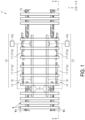
Fig. 1 is a plan view schematically showing a workpiece transport apparatus in accordance with a first embodiment. -
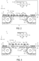
Fig. 2 is a cross-sectional view taken along line 2-2 inFig. 1 . -
Fig. 3 is a diagram illustrating operation of the workpiece transport apparatus. -
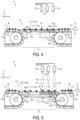
Fig. 4 is a diagram illustrating operation of the workpiece transport apparatus. -
Fig. 5 is a diagram illustrating operation of the workpiece transport apparatus. -
Fig. 6 is a diagram schematically showing a workpiece transport apparatus in accordance with a second embodiment. - A workpiece transport apparatus and a workpiece transport method in accordance with a first embodiment will now be described with reference to the drawings. For convenience of explanation, some of the elements may be illustrated in an exaggerated or simplified manner in the drawings. Further, elements in the drawings may not be to scale.
- As shown in
Figs. 1 and2 , aworkpiece transport apparatus 11 includes aninspection section 12 where workpieces W are inspected and afirst conveyor device 13 that transports the workpieces W to theinspection section 12. Theworkpiece transport apparatus 11 further includes an inspectionsection transport device 14 that transports the workpieces W in theinspection section 12. Theworkpiece transport apparatus 11 of the present embodiment further includes asecond conveyor device 15 that transports the workpieces W unloaded from theinspection section 12. As shown inFig. 2 , theworkpiece transport apparatus 11 further includes acontroller 16. - As shown in
Fig. 1 , each workpiece W of the present embodiment has an elongated shape and includes a first end Wa and a second end Wb in a longitudinal direction. Theworkpiece transport apparatus 11 transports the workpieces W such that the longitudinal direction of each workpiece W is orthogonal to a transport direction in plan view. Specifically, the workpiece W of the present embodiment is a glass tube. Theworkpiece transport apparatus 11 transports the glass tubes such that the tube-axis direction of each glass tube is orthogonal to the transport direction. The X-direction shown in the drawings corresponds to the transport direction. The Y-direction shown in the drawing corresponds to the longitudinal direction of the workpiece W, or a direction parallel to the tube axis of the glass tube. The Z-direction corresponds to the vertical direction. - As shown in
Figs. 2 to 5 , theinspection section 12 of the present embodiment includes a first image capturingdevice 12a, a secondimage capturing device 12b, and a thirdimage capturing device 12c. The first image capturingdevice 12a, the secondimage capturing device 12b, and the thirdimage capturing device 12c are arranged in this order from an upstream side with respect to the transport direction of the workpieces W. - As shown in
Fig. 5 , the workpieces W are inspected at predetermined inspection positions in theinspection section 12. The workpiece W located at a first inspection position P1 is imaged by the first image capturingdevice 12a. The workpiece W located at a second inspection position P2 is imaged by the secondimage capturing device 12b. The workpiece W located at a third inspection position P3 is imaged by the thirdimage capturing device 12c. - The first image capturing
device 12a, the secondimage capturing device 12b, and the thirdimage capturing device 12c capture images of the workpieces W for inspection. For example, the workpieces W are inspected for end-shape defects, cleanliness, and the like. The image capturing device may be, for example, a camera including an image capturing element such as CCD or CMOS. Theinspection section 12 may include, for example, a lighting device arranged facing the image capturing device. - As shown in
Figs. 1 and2 , thefirst conveyor device 13 of theworkpiece transport apparatus 11 is arranged at the upstream side of theinspection section 12. Thefirst conveyor device 13 includes twofirst conveyor devices 13 respectively provided for the first end Wa and the second end Wb of the workpiece W. As shown inFig. 2 , eachfirst conveyor device 13 includes an endlessfirst belt 13a and firstsupports 13b arranged on thefirst belt 13a. The twofirst conveyor devices 13 transport the workpieces W such that the longitudinal direction of each workpiece W is orthogonal to the transport direction of the workpieces W in plan view. Thefirst conveyor devices 13 of the present embodiment continuously transport the workpieces W to theinspection section 12 at a fixed speed. - As shown in
Fig. 1 , the inspectionsection transport device 14 of theworkpiece transport apparatus 11 includes two inspectionsection transport devices 14 respectively provided for the first end Wa and the second end Wb of the workpiece W. As shown inFig. 5 , the inspectionsection transport devices 14 of theworkpiece transport apparatus 11 temporarily stop transportation of the workpieces W at the first inspection position P1, the second inspection position P2, and the third inspection position P3. Further, the inspectionsection transport devices 14 transport the workpieces W to the first inspection position P1 at a higher transport speed than a loading speed at which thefirst conveyor device 13 transport the workpieces W to theinspection section 12. - As shown in
Figs. 1 to 5 , the inspectionsection transport device 14 of the present embodiment includes a holdingunit 17 and aworkpiece carrier 18. The holdingunit 17 holds the workpieces W. Theworkpiece carrier 18 loads the workpieces W to the holdingunit 17 and unloads the workpieces Wfrom the holdingunit 17. The holdingunit 17 includes afirst holding portion 17a and asecond holding portion 17b arranged at the downstream side of thefirst holding portion 17a. Thesecond holding portion 17b is arranged in correspondence with the inspection positions where the workpieces W are inspected. - The
first holding portion 17a holds one or more workpieces W in a state in which the workpieces W are stationary. Thesecond holding portion 17b includes a rolling mechanism that rolls the workpieces W at the inspection positions. More specifically, thesecond holding portion 17b includes rotary bodies, and each workpiece W is held and rotated by two adjacent ones of the rotary bodies about the axis of the workpiece W. The glass tube, which is the workpiece W in the present embodiment, is rotated about the tube axis. - As shown in
Figs. 2 to 5 , theworkpiece carrier 18 includes acarrier support member 18a that supports the workpieces W. Thecarrier support member 18a is moved by a parallel crank mechanism. More specifically, theworkpiece carrier 18 includes tworotation shafts 18b and adrive unit 18c. Thedrive unit 18c drives and rotates at least one of the tworotation shafts 18b. Further, theworkpiece carrier 18 includes twoarms 18d and twocoupling portions 18e. The twoarms 18d are rotated by the tworotation shafts 18b. The twocoupling portions 18e rotatably couple thearms 18d and thecarrier support member 18a. - In this manner, the inspection
section transport device 14 transports the workpieces W in theinspection section 12 by actuation of the parallel crank mechanism. Preferably, the inspectionsection transport device 14 has a stopping phase in which the actuation of the parallel crank mechanism is stopped during transporting the workpieces W. - The
carrier support member 18a of theworkpiece carrier 18 is configured to support more than one workpiece W. More specifically, as shown inFigs. 1 and2 , thecarrier support member 18a includes carrier supports 19 that support the workpieces W. Further, thesecond holding portion 17b is configured to hold the workpieces W at the inspection positions, such as the first inspection position P1, the second inspection position P2, and the like. In the present embodiment, the distances between the carrier supports 19, the distances between the workpieces W held by thefirst holding portion 17a, and the distances between the workpieces W held by thesecond holding portion 17b are set to align with the distances between the first inspection position P1, the second inspection position P2, and the third inspection position P3. - The intervals between the first supports 13b of the
first conveyor device 13 are smaller than the intervals between the carrier supports 19 of thecarrier support member 18a. - As shown in
Figs. 1 and2 , thesecond conveyor device 15 of theworkpiece transport apparatus 11 is arranged at the downstream side of theinspection section 12. Thesecond conveyor device 15 transports the workpieces W unloaded from the inspectionsection transport device 14. In the same manner as thefirst conveyor device 13, thesecond conveyor device 15 includes twosecond conveyor devices 15 respectively provided for the first end Wa and the second end Wb of the workpiece W. As shown inFig. 2 , eachsecond conveyor device 15 includes an endlesssecond belt 15a andsecond supports 15b arranged on thesecond belt 15a. The twosecond conveyor devices 15 transport the workpieces W such that the longitudinal direction of each workpiece W is orthogonal to the transport direction of the workpiece W in plan view. Thesecond conveyor devices 15 of the present embodiment transport the workpieces W that underwent inspection in theinspection section 12 to asorting device 20. For example, the sortingdevice 20 includes a sorting mechanism that separates defective glass tubes from the transport path of non-defective glass tubes. - The
controller 16 determines whether each workpiece W is anomalous based on images obtained by the firstimage capturing device 12a, the secondimage capturing device 12b, and the thirdimage capturing device 12c. The firstimage capturing device 12a, the secondimage capturing device 12b, and the thirdimage capturing device 12c obtain images of, for example, an end of the workpiece W, the outer circumferential surface of the workpiece W, and the like. Thecontroller 16 includes, for example, an image processor, memory, and the like. For example, the image processor may be configured to perform image processing, such as binary processing, brightness correction, and the like, on images including the workpiece Was necessary. For example, the memory may store in advance images of a normal workpiece W, a brightness threshold value, and the like. Thecontroller 16 may include a processor, memory, software, an image display device, and the like (not shown). - The
controller 16 may determine the state of each workpiece W, for example, by comparing a threshold value that is obtained from images of a normal workpiece W stored in the memory in advance with a value that is obtained from actual images captured by the image processor. Thecontroller 16 may use a learning model that is constructed through deep learning in determining whether the workpiece W is anomalous. For example, the learning model is an artificial intelligence (Al) model such as a neural network model. Based on the determination result of thecontroller 16, the sortingdevice 20 separates defective workpiece from non-defective workpieces. - A method for transporting the workpieces W will now be described along with its main effects.
- As shown in
Fig. 2 , the method for transporting the workpieces W includes a loading step of continuously transporting the workpieces W to theinspection section 12, where the workpieces W are inspected, with thefirst conveyor device 13. Further, as shown inFigs. 2 to 5 , the method for transporting the workpieces W includes an inspection section transporting step of transporting the workpieces W in theinspection section 12 with the inspectionsection transport device 14. - In the inspection section transporting step of the present embodiment, for example, transportation of the workpieces W is temporarily stopped at the first inspection position P1 where workpieces W are inspected. Specifically, the
second holding portion 17b is arranged, for example, at the first inspection position P1 to hold the workpiece W at a predetermined position. By holding the workpiece W in thesecond holding portion 17b, it becomes possible to inspect the workpiece W in a state in which transportation of the workpiece W is temporarily stopped at the first inspection position P1. The workpiece W can also be inspected at the second inspection position P2 and the third inspection position P3 in a state in which transportation of the workpiece W is temporarily stopped. After the workpiece W is inspected at the first inspection position P1, theworkpiece carrier 18 carries the workpiece W again such that inspection is sequentially performed at the second inspection position P2 and the third inspection position P3. - As described above, the method for transporting the workpieces W allows the workpieces W to be inspected at a high degree of accuracy in a state in which transportation of the workpieces W is temporarily stopped, for example, at the first inspection position P1. This improves the accuracy in inspecting the workpieces W.
- In the inspection section transporting step, the transport speed of the workpieces W to the first inspection position P1 where the workpieces Ware inspected is higher than a loading speed of the workpieces W in the loading step. Thus, even when the workpieces Ware transported in above-described inspection section transporting step, it is possible to maintain the loading speed of the workpieces W in the loading step at a predetermined speed or higher. Further, if the transport speed of the workpieces W to the first inspection position P1 is further increased in the inspection section transporting step, for example, the workpieces W can be stopped at the first inspection position P1 for a longer period.
- In the inspection section transporting step, the parallel crank mechanism moves the
carrier support member 18a. Preferably, the inspection section transporting step includes a stopping phase in which actuation of the parallel crank mechanism is stopped. In this case, the timing of the operation of theworkpiece carrier 18 is readily adjusted. For example, the period during which transportation of the workpieces W is temporarily stopped at the first inspection position P1 is readily adjusted. -
- (1-1) The method for transporting the workpieces W includes inspection section transporting step of transporting the workpieces W in the
inspection section 12 with the inspectionsection transport device 14. In the inspection section transporting step, for example, transportation of the workpieces W is temporarily stopped at the first inspection position P1 where the workpieces Ware inspected. This method enables improvement of the accuracy in inspecting the workpieces W, for example, at the first inspection position P1. - (1-2) The method for transporting the workpieces W further includes the loading step of continuously transporting the workpieces W to the
inspection section 12 with thefirst conveyor device 13. In the inspection section transporting step, the workpieces W are transported to the first inspection position P1 at a higher transport speed than the loading speed in the loading step. Thus, even when the workpieces W are transported in the above-described inspection section transporting step, it is possible to maintain the loading speed of the workpieces W in the loading step at a predetermined speed or higher. Therefore, it is possible to suppress a decrease in the transport efficiency of the workpieces W. - (1-3) The first supports 13b of the
first conveyor device 13 may be selectively used in accordance with, for example, the dimension of the workpiece W. For example, when each workpiece W has a relatively large dimension, every other one of the first supports 13b of thefirst conveyor device 13 may support the workpieces W to avoid contact between adjacent workpieces W. - In the above embodiment, the intervals between the first supports 13b of the
first conveyor device 13 are smaller than the intervals between the carrier supports 19 of the inspectionsection transport device 14. By setting the intervals between the first supports 13b as described above, the loading speed of the workpieces W to theinspection section 12 can be maintained at a predetermined speed or higher even when, for example, every otherfirst support 13b is used. The number offirst supports 13b and the number of carrier supports 19 are each three or more, preferably four or more, and further preferably, five or more. - (1-4) The inspection
section transport device 14 includes thesecond holding portion 17b and theworkpiece carrier 18. In this case, thesecond holding portion 17b holds the workpieces W transported by theworkpiece carrier 18 so that transportation of the workpieces W is readily stopped, for example, at the first inspection position P1. - (1-5) The
workpiece carrier 18 includes thecarrier support member 18a that supports the workpieces W. Thecarrier support member 18a is moved by the parallel crank mechanism. Thus, the workpieces W are transported with a relatively simple structure. - (1-6) Preferably, the inspection section transporting step includes a stopping phase in which the actuation of the parallel crank mechanism of the
workpiece carrier 18 is stopped. In this case, the timing of the operation of theworkpiece carrier 18 is readily adjusted. For example, the period during which transportation of the workpieces W is temporarily stopped at the first inspection position P1 is readily adjusted. - (1-7) In the method for transporting the workpieces W, each workpiece W has an elongated shape and is transported such that the longitudinal direction of the workpiece W is orthogonal to the transport direction. This enables improvement of the accuracy in inspecting such elongated workpieces W.
- (1-8) The
carrier support member 18a of theworkpiece carrier 18 is configured to support more than one workpiece W. Thesecond holding portion 17b is configured to hold the workpiece W at each of the inspection positions (such as the first inspection position P1 and the second inspection position P2). In this case, for example, more than one workpiece W can be simultaneously inspected in theinspection section 12. Also, multiple types of inspections may be performed on each workpiece W. - (1-9) The
second holding portion 17b of the inspectionsection transport device 14 includes, for example, the roll mechanism that rolls the workpieces W at the first inspection position P1. In this case, inspection is readily performed along the outer circumference of the workpiece W. - A
workpiece transport apparatus 11 and a method for transporting workpieces W in accordance with a second embodiment will now be described focusing on differences from the first embodiment. - As shown in
Fig. 6 , theworkpiece transport apparatus 11 of the second embodiment includes athird conveyor device 21 that loads the workpieces W to theinspection section 12 and unloads the workpieces W from theinspection section 12. Thethird conveyor device 21 includes an endlessthird belt 21a andthird supports 21b arranged on thethird belt 21a. - The
workpiece transport apparatus 11 includes an inspectionsection transport device 22. The inspectionsection transport device 22 includes a rotation mechanism that transports the workpieces W along an arc-shaped transport path. The inspectionsection transport device 22 includesrollers 23 that support the workpieces W such that each workpiece W is rotatable about the axis of the workpieces W. Each workpiece W is supported by a support portion formed by two adjacent ones of therollers 23. In the example shown inFig. 6 , eachroller 23 rotates counterclockwise. In this case, therollers 23 collectively turn along a circular path in the clockwise direction. The inspectionsection transport device 22 successively transports the workpieces W along an arc-shaped path in the clockwise direction while rotating each workpiece W about the corresponding axis in the clockwise direction. - Specifically, the inspection
section transport device 22 includes a main-mechanism unit 24 that is substantially circular in side view of the inspectionsection transport device 22, and therollers 23 are rotatably arranged on the outer circumferential portion of the main-mechanism unit 24. When the main-mechanism unit 24 of the inspectionsection transport device 22 is rotated by adrive unit 25, the main-mechanism unit 24 turns therollers 23 collectively. The inspectionsection transport device 22 having such a structure forms an arc-shaped transport path (arcuate path) that projects upward. - Further, each
roller 23 includes apower transmission portion 26, such as a transmission sprocket, a gear, or the like, and is rotated by the driving force transmitted from a sub-mechanism unit 27. The sub-mechanism unit 27 is rotated by adrive unit 28 that differs from thedrive unit 25 of the main-mechanism unit 24. This rotates therollers 23 as described above. Thus, the inspectionsection transport device 22 of the second embodiment also includes a rolling mechanism that rolls the workpieces W, for example, at the first inspection position P1. - An example of setting the transport speed of the workpieces W in the
workpiece transport apparatus 11 of the second embodiment will now be described. - The
workpiece transport apparatus 11 includes a first transport region R1 where the workpieces W are transported at a first transport speed S1 with thethird conveyor device 21. Further, theinspection section 12 of theworkpiece transport apparatus 11 includes a second transport region R2 where the workpieces W are transported at a second transport speed S2, and a third transport region R3 where the workpieces W are transported at a third transport speed S3. The second transport region R2 includes a region from the upstream end of theinspection section 12 to a vicinity of the first inspection position P1, a region from a vicinity of the first inspection position P1 to a vicinity of the second inspection position P2, and a region from a vicinity of the second inspection position P2 to a vicinity of the third inspection position P3. The third transport region R3 corresponds to a range in which the workpiece W starts and ends passing an inspection position, such as the first inspection position P1, the second inspection position P2, or the third inspection position P3. - The first transport speed S1, the second transport speed S2, and the third transport speed S3 satisfy the following relational expression (1).

- In this manner, in the inspection section transporting step of the second embodiment, the transport speed of the workpieces W is decreased, for example, at the first inspection position P1. Further, in the inspection section transporting step of the second embodiment, the transport speed of the workpieces W to the first inspection position P1 is higher than the loading speed of the workpieces W in the loading step, in the same manner as the first embodiment.
- The operation and advantages of the second embodiment will now be described.
- (2-1) In the inspection section transporting step, for example, the transport speed of the workpieces W is decreased at the first inspection position P1. Thus, the workpieces W can be inspected at a high degree of accuracy when the transport speed of workpieces W is decreased at the first inspection position P1. Therefore, it enables improvement of the accuracy in inspecting the workpieces W at the first inspection position P1.
- (2-2) The method for transporting the workpieces W further includes the loading step of continuously transporting the workpieces W to the
inspection section 12 with thethird conveyor device 21. In the inspection section transporting step, the workpieces W are transported to the first inspection position P1 at a higher transport speed than the loading speed of the workpieces W in the loading step. Thus, even when the workpieces W are transported in the above-described inspection section transporting step, it is possible to maintain the loading speed of the workpieces W in the loading step at a predetermined speed or higher. Therefore, it is possible to suppress a decrease in the transport efficiency of the workpieces W. - (2-3) The
third conveyor device 21 includes thethird supports 21b. The inspectionsection transport device 22 includes support portions each formed by two adjacent ones of therollers 23. The intervals between the third supports 21b are smaller than the intervals between the support portions of the inspectionsection transport device 22. This obtains the same advantage as advantage (1-3) of the first embodiment. The number ofthird supports 21b of thethird conveyor device 21 and the number of support portions of the inspectionsection transport device 22 are each three or more, preferably four or more, further preferably, five or more. - (2-4) The second embodiment has the same advantages as advantages (1-7) to (1-9) of the first embodiment.
- The above embodiments may be modified as follows. The above embodiments and the following modifications can be combined as long as the combined modifications remain technically consistent with each other.
- The elongated workpiece W does not have to have a circular cross section, and the cross-sectional shape may be, for example, elliptical or polygonal.
- The workpiece W does not have to has an elongated shape and may be, for example, spherical or polygonal.
- The material of the workpiece W is not limited to glass and may be, for example, metal, resin, or ceramics.
- The
first holding portion 17a may be omitted from the inspectionsection transport device 14 of the first embodiment. In other words, the workpieces W transported to theinspection section 12 may be directly transported to the first inspection position P1 with theworkpiece carrier 18. - In the
workpiece carrier 18 of the first embodiment, thecarrier support member 18a of the inspectionsection transport device 14 may be moved by a mechanism that is not the parallel crank mechanism. For example, thecarrier support member 18a can be modified such that thecarrier support member 18a is movable by a robot arm. - In the second embodiment, the inspection
section transport device 22 may be changed to a transport device that performs transportation along a horizontal transport path. - In the second embodiment, the inspection
section transport device 22 can temporarily stop transportation of the workpieces W at the inspection positions. In other words, in the method for transporting the workpieces W, the inspectionsection transport device 22 of the second embodiment may be used to temporarily stop transportation of the workpieces W at the inspection positions in the inspection section transporting step. - In the first embodiment, the intervals between the first supports 13b of the
first conveyor device 13 may be greater than or equal to the intervals between the carrier supports 19 of the inspectionsection transport device 14. Further, the intervals between the second supports 15b of thesecond conveyor device 15 may be changed. - In the second embodiment, the intervals between the third supports 21b of the
third conveyor device 21 may be greater than or equal to the intervals between the support portions of the inspectionsection transport device 22, each formed by twoadjacent rollers 23 supporting one workpiece W. - In the first embodiment, the
carrier support member 18a of the inspectionsection transport device 14 and thesecond holding portion 17b may each hold a single workpiece W. In the first embodiment, thefirst conveyor device 13 may have a singlefirst support 13b, and thesecond conveyor device 15 may have a singlesecond support 15b. - In the second embodiment, the inspection
section transport device 22 may support a single workpiece W. In the second embodiment, the third conveyor device may have a singlethird support 21b. - In the first and second embodiments, the transport speed of the workpieces W to the first inspection position P1 in the inspection
section transporting step 12 may be the same as the loading speed of the workpieces W in the loading step. In other words, the loading speed of the workpieces W in the loading step may be changed to match the transport speed of the workpieces W in the inspection section transporting step. - In the first and second embodiments, the inspection
section transport devices workpiece transport apparatus 11 are arranged as a pair in a direction orthogonal to the transport direction. Instead, the number of inspectionsection transport devices - In the first embodiment, the
first conveyor devices 13 of theworkpiece transport apparatus 11 are arranged as a pair in a direction orthogonal to the transport direction. Instead, the number offirst conveyor devices 13 may be one or three or more. Also, the number ofsecond conveyor devices 15 of theworkpiece transport apparatus 11 may be one or three or more. - In the second embodiment, the
third conveyor devices 21 of theworkpiece transport apparatus 11 are arranged as a pair in a direction orthogonal to the transport direction. Instead, the number ofthird conveyor devices 21 may be one or three or more. - At the first inspection position P1, the second inspection position P2, and the third inspection position P3 in the
inspection section 12, the workpieces W are inspected using images of the workpieces W. Instead, the workpieces W may be inspected visually or using an inspection device other than an image capturing device. - The number of inspection positions in the
inspection section 12 does not have to be three and may be one, two, four or more. - 11) workpiece transport apparatus; 12) inspection section; 13) first conveyor device; 13b) first support; 14, 22) inspection section transport device; 17b) second holding portion; 18) workpiece carrier; 18a) carrier support member; 19) carrier support; 21) third conveyor device; 21b) third support; P1) first inspection position; P2) second inspection position; P3) third inspection position; W) workpiece
Claims (9)
- A method for transporting workpieces, the method comprising:an inspection section transporting step of transporting the workpieces in an inspection section, where the workpieces are inspected, with an inspection section transport device,wherein the inspection section transporting step includes decreasing a transport speed of the workpieces at an inspection position where the workpieces are inspected or temporarily stopping transportation of the workpieces at the inspection position.
- The method for transporting workpieces according to claim 1, further comprising:a loading step of continuously loading the workpieces to the inspection section with a conveyor device,wherein in the inspection section transporting step, the transport speed of the workpieces to the inspection position is higher than a loading speed of the workpieces in the loading step.
- The method for transporting workpieces according to claim 2, whereinthe conveyor device and the inspection section transport device each include supports that support the workpieces, andthe intervals between the supports of the conveyor device are smaller than the intervals between the supports of the inspection section transport device.
- The method for transporting workpieces according to any one of claims 1 to 3, wherein:the inspection section transport device includesa holding unit arranged in correspondence with the inspection position to hold the workpieces, anda workpiece carrier that loads the workpieces to the holding unit and unloads the workpieces from the holding unit; andin the inspection section transporting step, transportation of the workpieces is temporarily stopped at the inspection position.
- The method for transporting workpieces according to claim 4, whereinthe workpiece carrier includes a carrier support member that supports the workpieces, andthe carrier support member is moved by a parallel crank mechanism.
- The method for transporting workpieces according to claim 5, wherein the inspection section transporting step includes a stopping phase in which actuation of the parallel crank mechanism is stopped.
- The method for transporting workpieces according to any one of claims 1 to 3, wherein the inspection section transport device transports the workpieces along an arc-shaped transport path.
- The method for transporting workpieces according to any one of claims 1 to 7, wherein each of the workpieces has an elongated shape and is transported such that a longitudinal direction of the workpieces is orthogonal to a transport direction.
- A workpiece transport apparatus, comprising:an inspection section transport device that transports workpieces in an inspection section where the workpieces are inspected,wherein the inspection section transport device decreases a transport speed of the workpieces at an inspection position where the workpieces are inspected or temporarily stops transportation of the workpieces at the inspection position.
Applications Claiming Priority (2)
| Application Number | Priority Date | Filing Date | Title |
|---|---|---|---|
| JP2021205242A JP7779126B2 (en) | 2021-12-17 | 2021-12-17 | Workpiece transport method and workpiece transport device |
| PCT/JP2022/044459 WO2023112711A1 (en) | 2021-12-17 | 2022-12-01 | Workpiece transport method and workpiece transport device |
Publications (2)
| Publication Number | Publication Date |
|---|---|
| EP4450428A1 true EP4450428A1 (en) | 2024-10-23 |
| EP4450428A4 EP4450428A4 (en) | 2025-12-10 |
Family
ID=86774276
Family Applications (1)
| Application Number | Title | Priority Date | Filing Date |
|---|---|---|---|
| EP22907239.2A Pending EP4450428A4 (en) | 2021-12-17 | 2022-12-01 | WORKPIECE TRANSPORT METHOD AND WORKPIECE TRANSPORT DEVICE |
Country Status (4)
| Country | Link |
|---|---|
| EP (1) | EP4450428A4 (en) |
| JP (1) | JP7779126B2 (en) |
| CN (1) | CN118369280A (en) |
| WO (1) | WO2023112711A1 (en) |
Family Cites Families (7)
| Publication number | Priority date | Publication date | Assignee | Title |
|---|---|---|---|---|
| US5405015A (en) * | 1993-08-11 | 1995-04-11 | Videojet Systems International, Inc. | System and method for seeking and presenting an area for reading with a vision system |
| JP3768036B2 (en) * | 1999-06-30 | 2006-04-19 | 株式会社キリンテクノシステム | Container inspection device |
| JP6083667B2 (en) * | 2012-10-16 | 2017-02-22 | 東芝Itコントロールシステム株式会社 | Inspection equipment |
| JP6352027B2 (en) * | 2014-03-31 | 2018-07-04 | 株式会社エヌテック | Container inspection device |
| DE102014226965A1 (en) * | 2014-12-23 | 2016-06-23 | Krones Ag | Apparatus and method for the continuous inspection of containers |
| JP6561698B2 (en) * | 2015-09-01 | 2019-08-21 | 株式会社豊田自動織機 | Work inspection device |
| JP2018017547A (en) | 2016-07-26 | 2018-02-01 | 日本電気硝子株式会社 | Method for inspecting glass article, method for manufacturing glass article and device for inspecting glass article |
-
2021
- 2021-12-17 JP JP2021205242A patent/JP7779126B2/en active Active
-
2022
- 2022-12-01 CN CN202280080842.5A patent/CN118369280A/en active Pending
- 2022-12-01 WO PCT/JP2022/044459 patent/WO2023112711A1/en not_active Ceased
- 2022-12-01 EP EP22907239.2A patent/EP4450428A4/en active Pending
Also Published As
| Publication number | Publication date |
|---|---|
| JP2023090323A (en) | 2023-06-29 |
| WO2023112711A1 (en) | 2023-06-22 |
| CN118369280A (en) | 2024-07-19 |
| EP4450428A4 (en) | 2025-12-10 |
| JP7779126B2 (en) | 2025-12-03 |
Similar Documents
| Publication | Publication Date | Title |
|---|---|---|
| US12578282B2 (en) | Apparatus and method for inspecting a glass sheet | |
| KR102752375B1 (en) | Rotary-Type Automated Vision System for Quality Inspection of Tube Cross-section | |
| US11533441B2 (en) | Systems and methods for three-hundred sixty degree inspection of an object | |
| US12131930B2 (en) | Inspection system | |
| US11264263B2 (en) | Conveyor inspection system, substrate rotator, and test system having the same | |
| CN109238171B (en) | Fully automatic cylindrical glass rod visual inspection equipment | |
| CN110736753A (en) | A double-speed chain transmission device, roller line scan detection system and detection method | |
| JP2002350358A (en) | Apparatus for inspecting appearance of cylindrical workpiece, appearance inspection method, appearance inspection program, and recording medium | |
| JP2018017547A (en) | Method for inspecting glass article, method for manufacturing glass article and device for inspecting glass article | |
| JP2001219127A (en) | Appearance inspection and appearance inspection device used for this method | |
| KR101967372B1 (en) | Inspection apparatus, and inspection method using the same apparatus | |
| KR20160066741A (en) | apparatus for examining edge of flat panel display panel and method of using the same | |
| CN110712982A (en) | Offline Inspection System for Surface Defects of Nuclear Fuel Pellets | |
| JP6907862B2 (en) | Internal surface inspection device for pipes | |
| JP7779126B2 (en) | Workpiece transport method and workpiece transport device | |
| CN119387182A (en) | An automatic testing device for bar product quality | |
| JP4252381B2 (en) | Appearance inspection device | |
| CN211989743U (en) | Cylindrical workpiece detection platform | |
| JP2022124812A (en) | Check device, check method, and program | |
| JP2023156781A (en) | Roll inspection method and roll inspection device | |
| CN114365272B (en) | Conveyor inspection system, substrate rotator, and test system having the foregoing items. | |
| JPH066103Y2 (en) | Aligning and transporting device for cylinders | |
| JPS6241109A (en) | Cylindrical material conveying device | |
| JP2022087726A (en) | External surface inspection device | |
| JP2008082704A (en) | Substrate inspection device and substrate inspection method |
Legal Events
| Date | Code | Title | Description |
|---|---|---|---|
| STAA | Information on the status of an ep patent application or granted ep patent |
Free format text: STATUS: THE INTERNATIONAL PUBLICATION HAS BEEN MADE |
|
| PUAI | Public reference made under article 153(3) epc to a published international application that has entered the european phase |
Free format text: ORIGINAL CODE: 0009012 |
|
| STAA | Information on the status of an ep patent application or granted ep patent |
Free format text: STATUS: REQUEST FOR EXAMINATION WAS MADE |
|
| 17P | Request for examination filed |
Effective date: 20240709 |
|
| AK | Designated contracting states |
Kind code of ref document: A1 Designated state(s): AL AT BE BG CH CY CZ DE DK EE ES FI FR GB GR HR HU IE IS IT LI LT LU LV MC ME MK MT NL NO PL PT RO RS SE SI SK SM TR |
|
| DAV | Request for validation of the european patent (deleted) | ||
| DAX | Request for extension of the european patent (deleted) | ||
| A4 | Supplementary search report drawn up and despatched |
Effective date: 20251106 |
|
| RIC1 | Information provided on ipc code assigned before grant |
Ipc: B65G 43/00 20060101AFI20251031BHEP Ipc: G01N 21/84 20060101ALI20251031BHEP Ipc: G01N 21/954 20060101ALI20251031BHEP Ipc: B65G 43/08 20060101ALI20251031BHEP Ipc: B65G 43/10 20060101ALI20251031BHEP Ipc: G01N 21/90 20060101ALI20251031BHEP Ipc: G01N 21/958 20060101ALI20251031BHEP Ipc: B65G 47/66 20060101ALI20251031BHEP Ipc: B65G 25/02 20060101ALI20251031BHEP Ipc: B65G 17/24 20060101ALI20251031BHEP |