EP4450422A1 - Method and system for handling compressible acoustic panels - Google Patents
Method and system for handling compressible acoustic panels Download PDFInfo
- Publication number
- EP4450422A1 EP4450422A1 EP23168662.7A EP23168662A EP4450422A1 EP 4450422 A1 EP4450422 A1 EP 4450422A1 EP 23168662 A EP23168662 A EP 23168662A EP 4450422 A1 EP4450422 A1 EP 4450422A1
- Authority
- EP
- European Patent Office
- Prior art keywords
- box
- shaped distribution
- side wall
- distribution unit
- wall portion
- Prior art date
- Legal status (The legal status is an assumption and is not a legal conclusion. Google has not performed a legal analysis and makes no representation as to the accuracy of the status listed.)
- Granted
Links
Images




Classifications
-
- B—PERFORMING OPERATIONS; TRANSPORTING
- B65—CONVEYING; PACKING; STORING; HANDLING THIN OR FILAMENTARY MATERIAL
- B65D—CONTAINERS FOR STORAGE OR TRANSPORT OF ARTICLES OR MATERIALS, e.g. BAGS, BARRELS, BOTTLES, BOXES, CANS, CARTONS, CRATES, DRUMS, JARS, TANKS, HOPPERS, FORWARDING CONTAINERS; ACCESSORIES, CLOSURES, OR FITTINGS THEREFOR; PACKAGING ELEMENTS; PACKAGES
- B65D85/00—Containers, packaging elements or packages, specially adapted for particular articles or materials
- B65D85/07—Containers, packaging elements or packages, specially adapted for particular articles or materials for compressible or flexible articles
-
- B—PERFORMING OPERATIONS; TRANSPORTING
- B65—CONVEYING; PACKING; STORING; HANDLING THIN OR FILAMENTARY MATERIAL
- B65B—MACHINES, APPARATUS OR DEVICES FOR, OR METHODS OF, PACKAGING ARTICLES OR MATERIALS; UNPACKING
- B65B35/00—Supplying, feeding, arranging or orientating articles to be packaged
- B65B35/30—Arranging and feeding articles in groups
- B65B35/50—Stacking one article, or group of articles, upon another before packaging
-
- B—PERFORMING OPERATIONS; TRANSPORTING
- B65—CONVEYING; PACKING; STORING; HANDLING THIN OR FILAMENTARY MATERIAL
- B65B—MACHINES, APPARATUS OR DEVICES FOR, OR METHODS OF, PACKAGING ARTICLES OR MATERIALS; UNPACKING
- B65B63/00—Auxiliary devices, not otherwise provided for, for operating on articles or materials to be packaged
- B65B63/02—Auxiliary devices, not otherwise provided for, for operating on articles or materials to be packaged for compressing or compacting articles or materials prior to wrapping or insertion in containers or receptacles
-
- B—PERFORMING OPERATIONS; TRANSPORTING
- B65—CONVEYING; PACKING; STORING; HANDLING THIN OR FILAMENTARY MATERIAL
- B65D—CONTAINERS FOR STORAGE OR TRANSPORT OF ARTICLES OR MATERIALS, e.g. BAGS, BARRELS, BOTTLES, BOXES, CANS, CARTONS, CRATES, DRUMS, JARS, TANKS, HOPPERS, FORWARDING CONTAINERS; ACCESSORIES, CLOSURES, OR FITTINGS THEREFOR; PACKAGING ELEMENTS; PACKAGES
- B65D5/00—Rigid or semi-rigid containers of polygonal cross-section, e.g. boxes, cartons or trays, formed by folding or erecting one or more blanks made of paper
- B65D5/42—Details of containers or of foldable or erectable container blanks
- B65D5/64—Lids
- B65D5/68—Telescope flanged lids
-
- B—PERFORMING OPERATIONS; TRANSPORTING
- B65—CONVEYING; PACKING; STORING; HANDLING THIN OR FILAMENTARY MATERIAL
- B65D—CONTAINERS FOR STORAGE OR TRANSPORT OF ARTICLES OR MATERIALS, e.g. BAGS, BARRELS, BOTTLES, BOXES, CANS, CARTONS, CRATES, DRUMS, JARS, TANKS, HOPPERS, FORWARDING CONTAINERS; ACCESSORIES, CLOSURES, OR FITTINGS THEREFOR; PACKAGING ELEMENTS; PACKAGES
- B65D85/00—Containers, packaging elements or packages, specially adapted for particular articles or materials
- B65D85/62—Containers, packaging elements or packages, specially adapted for particular articles or materials for stacks of articles; for special arrangements of groups of articles
Definitions
- the present invention relates to a method and a system for handling compressible acoustic panels.
- Panels of mineral fiber material such as glass wool are used for their sound dampening properties. To this end, such acoustic panels are often arranged in or suspended from a ceiling.
- a challenge with distributing acoustic panels is packaging and transportation.
- a typical ceiling tile made of glass wool consists of 95 v% air, wheras the remaining 5 v% is glass wool fibres. Consequently, the majority of the transported volume is air, which is problem both from a cost perspective and an environmental perspective.
- solutions Due to the compressible nature of such panels, a variety of solutions have been presented which entails reducing the volume of the panels during packaging and before transportation. Examples of solutions comprised in the state of the art can be found in EP 2 460 738 B1 and EP 3 181 477 B1 . Such solutions include compressing one or more panels with a securing member, or enclosing one or more acoustic panels in plastic wrapping, and connecting it to a pump in order to evacuate air.
- the securing member which often is provided in the form of a plastic wrapping, may be penetrated during transportation, either unintentionally or intentionally. This leaves the panels exposed to damage or soiling. In some cases, it may lead to the panels being decompressed, thereby bursting through the wrapping and complicating further handling thereof.
- an object of the present invention is to provide a solution for handling compressible acoustic panels in a space efficient manner while improving the protection of the panels, thereby reducing soiling and damage of the panels.
- Another object is to provide a solution which is more cost efficient and/or time efficient.
- a method for handling compressible acoustic panels comprising: providing a plurality of compressible acoustic panels; providing at least two box-shaped distribution units, each box-shaped distribution unit comprising: a top part and a bottom part, wherein each box-shaped distribution unit is bringable to an assembled state in which one of the top part and the bottom part is inserted into the other of the top part and the bottom part for defining a box volume having a box height h1; for each box-shaped distribution unit, forming a stack comprising at least two compressible acoustic panels obtained from said plurality of compressible acoustic panels, wherein each stack has an uncompressed height h2 which is greater than box height h1; arranging each stack in the bottom part of the associated box-shaped distribution unit; arranging the top part of the associated box-shaped distribution unit on top of each stack; stacking the at least two box-shaped distribution units and the stacks of compressible acoustic
- a system for handling compressible acoustic panels comprising: a plurality of compressible acoustic panels; at least two box-shaped distribution units, each box-shaped distribution unit comprising: a top part and a bottom part, wherein each box-shaped distribution unit is bringable to an assembled state in which one of the top part and the bottom part is inserted into the other of the top part and the bottom part for defining a box volume having a box height h1; and a securing member; wherein each box-shaped distribution unit is configured for receiving a stack comprising at least two compressible acoustic panels obtained from said plurality of compressible acoustic panels, wherein each stack has an uncompressed height h2 which is greater than box height h1; and the at least two box-shaped distribution units are configured to be stacked on top of each other and, in the assembled state, compress the compressible acoustic panels contained in the box-shaped distribution units such that each stack has
- the compressible acoustic panels are protected by the box-shaped distribution units during packaging, such as during stacking the at least two box-shaped distribution units and pressing the top part of the uppermost box-shaped distribution unit towards the bottom part of the lowermost box-shaped distribution unit. Furthermore, the compressible acoustic panels are protected during further handling of the stack of box-shaped distribution units, especially during transportation thereof.
- a compressible acoustic panel may e.g. be made of mineral fiber material, such as mineral wool. However, it is to be understood that a compressible acoustic panel may be made of any other suitable material, or combination of suitable materials.
- a box-shaped distribution unit may e.g. be made of any material, for example cardboard or plastic. Stacking the at least two box-shaped distribution units may involve any practically feasible number of box-shaped distribution units, such as three, four, five or ten box-shaped distribution units. It is naturally to be understood that the number of box-shaped distribution units, in practice, is limited by any means of storing and/or transporting the box-shaped distribution units in the assembled state.
- the stack of box-shaped distribution units may, after having been brought to the assembled state, be handled in a variety of ways.
- the stack may be loaded directly into a cargo space of a vehicle for distribution, wherein the dimensions of the cargo space restricts decompression of the compressible acoustic panels contained in the box-shaped distribution units, and thereby restricts the box-shaped distribution units from being brought from the the assembled state.
- the step of stacking may further comprise arranging the lowermost box-shaped distribution unit on a bottom end plate and arranging a top end plate on the uppermost box-shaped distribution unit.
- pressing the top part of the uppermost box-shaped distribution unit towards the bottom part of the lowermost box-shaped distribution unit may be facilitated by pressing the top end plate towards the bottom end plate.
- a more uniform pressure distribution is facilitated, and the risk of damaging the box-shaped distribution units during pressing is reduced.
- Any end plate may further be configured for receiving and releasably retaining the securing member.
- any end plate may e.g. be provided with a lug for receiving a strap, or a slit for receiving a plastic film.
- the step of pressing the top part of the uppermost box-shaped distribution unit towards the bottom part of the lowermost box-shaped distribution may be performed at a first location, wherein the method may further comprise: shipping the box-shaped distribution units in the assembled state to a second location different from the first location; arranging the box-shaped distribution units in the assembled state in a disassembly rack at the second location, the disassembly rack comprising a plurality of vertical rails configured to guide the box-shaped distribution units during the bringing thereof from the assembled state; and bringing each box-shaped distribution unit from the assembled state, thereby decompressing the compressible acoustic panels contained in the box-shaped distribution units.
- the stacks of compressible acoustic panels contained therein regains the decompressed height of h2.
- the duration of decompression may e.g. be 10 s, or 20 s, or 30 s, depending on the properties of the acoustic panels and the box-shaped distribution units.
- the disassembly rack guides the box-shaped distribution units during the bringing thereof from the assembled state is to be understood as the disassembly rack providing a physical perimeter so as to arrest the stack of one box-shaped distribution unit should it tilt during decompression of the compressible acoustic panels.
- the vertical rails of the rack may be in contact with the stack box-shaped distribution units during decompression.
- the stack box-shaped distribution units may be in contact with any number of vertical rails.
- the rack is not in contact with the box-shaped distribution units.
- the box-shaped distribution units may thus be arranged in the disassembly rack with a distance to each one of the vertical rails. The distance may e.g. be 1 cm, or 2 cm, or 3 cm.
- the method may further comprise: providing a securing member; and securing the at least two box-shaped distribution units by the securing member in the assembled state.
- the stack of box-shaped distribution units are restricted from being brought from the assembled state by the securing member.
- the box-shaped distribution units are easier to handle.
- Bringing each box-shaped distribution unit from the assembled state may further comprise releasing the securing member member.
- the securing member may e.g. be provided in the form of a strap.
- the strap is preferably arranged vertically along a longitudinal axis of stack of box-shaped distribution units and around the box-shaped distribution units such that the top part of the uppermost box-shaped distribution unit is restricted from moving away from the bottom part of the lowermost box-shaped distribution unit.
- the securing member may be provided in the form of a plastic film.
- the plastic film may be wrapped around the stack of box-shaped distribution units such that the box-shaped distribution units are at least partially enclosed in the plastic film.
- the box-shaped distribution units may be completely enclosed.
- each box-shaped distribution unit is bringable to an assembled state in which the top part is inserted the bottom part. In some embodiments, each box-shaped distribution unit is bringable to an assembled state in which the bottom part is inserted into the top part.
- a stack of box-shaped distribution unit may comprise at least one box-shaped distribution unit where the bottom part is inserted into the top part and at least one box-shaped distribution unit top part is inserted the bottom part.
- the top part may form a space for receiving the bottom part such that the box-shaped distribution may be bringable to the assembled state in which the bottom part is inserted into the top part.
- the top part may comprise a top wall portion and a plurality of side wall portions, wherein each side wall portion may have a respective first end portion connected to the top wall portion and a respective second end portion distal to the respective first end portion such that each side wall portion is arranged with a first extension perpendicular to a plane of extension of the top wall portion and parallel to the respective first extension of the other side wall portions of the plurality of side wall portions so as to form said space.
- the top part may comprise any number of side wall portions.
- the number of side wall portions is inter alia dependent on the shape of the top wall portion and/or the shape of the box-shaped distribution unit.
- the top part may comprise three side wall portions, or four side wall portions.
- the box-shaped distribution unit has a cuboid shape. More preferably, the box-shaped distribution unit may have a rectangular cuboid shape.
- the plurality of side wall portions may comprise four side wall portions, wherein each side wall portion may adjoin two other side wall portions of the four side wall portions, wherein each side wall portion may have a second extension parallel to the plane of extension of the top wall portion and perpendicular to the respective second extension of each adjoining side wall portion.
- each top part comprises a respective first side wall portion, second side wall portion, third side wall portion and fourth side wall portion, wherein the first side wall portion adjoins the second side wall portion and the fourth side wall portion, and the second side wall portion adjoins the first side wall portion and the third wall portion, and the third wall portion adjoins the second wall portion and the fourth wall portion, and the fourth wall portion adjoins the third wall portion and the first wall portion.
- Each side wall portion may be provided with a respective flap portion, wherein the step of pressing further comprises folding each flap portion towards and arranging each flap portion against the respective side wall portion.
- the flap portions Prior to being brought to the assembled state, when the top part is arranged on the stack of compressible panels arranged in the corresponding bottom part, the flap portions may be arranged against the stack so as to protect the stack from contaminants, such as dust.
- This enables the provision of side wall portions of smaller dimension such that the top part and the bottom part defines a box volume having a box height smaller than h1. Consequently, upon folding each flap portion towards and arranging each flap portion against the respective side wall portion, a larger extent of compression of the compressible panels is facilitated.
- an even more space-efficient method is provided.
- the system may further comprise a bottom end plate and a top end plate, wherein the bottom end plate is configured to be arranged such that a lowermost box-shaped distribution unit of a stack of box-shaped distribution is arranged on the bottom end plate, and wherein the top end plate is configured to be arranged on an uppermost box-shaped distribution unit of a stack of box-shaped distribution units.
- stacking the at least two box-shaped distribution units may further comprise arranging the lowermost box-shaped distribution unit of a stack of box-shaped distribution units on a bottom end plate and arranging a top end plate on the uppermost box-shaped distribution unit of the stack of box-shaped distribution units.
- the pressure on the box-shaped distribution units while being pressed may be more evenly distributed.
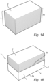
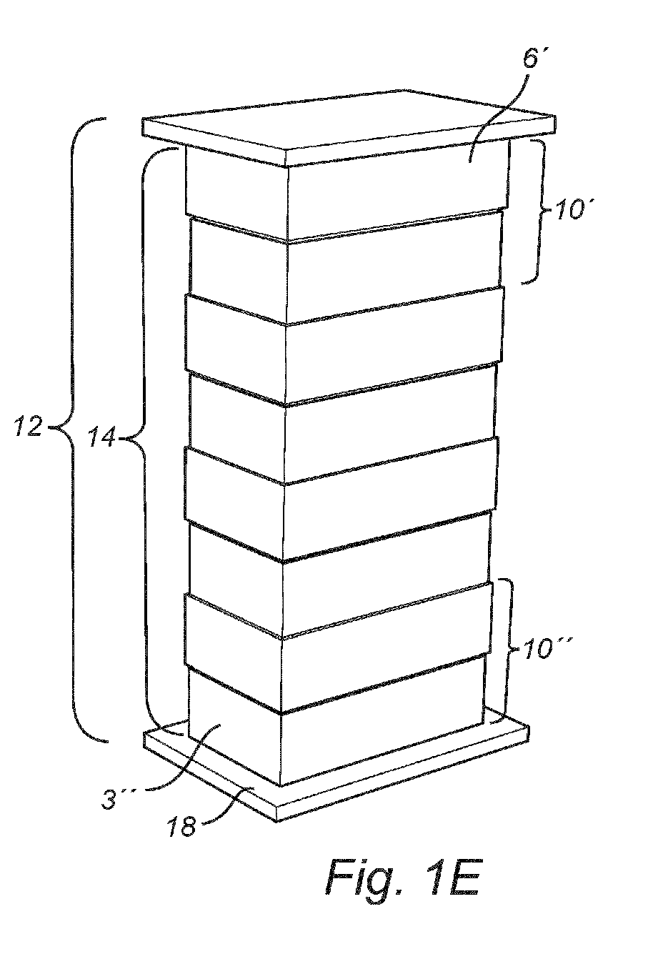
- Fig. 1A is a perspective view of a stack 1 of compressible acoustic panels 2.
- Any one compressible acoustic panel 2 may e.g. be made of mineral fiber material, such as mineral wool.
- a compressible acoustic panel 2 may be made of any other suitable material, or combination of suitable materials.
- the acoustic panels 2 may have any shape.
- an acoustic panel 2 may be circular, oblong, or polygonal.
- each acoustic panel 2 has rectangular cuboid shape.
- the stack 1 has a height h2.
- the height h2 is the height of the stack 1 when each compressible acoustic panel 2 is in an uncompressed state.
- Fig. 1B is a perspective view of the stack 1 arranged in a bottom part 3 of a box-shaped distribution unit 10 (shown in Fig. 1D ).
- a box-shaped distribution unit 10, and thereby the bottom part 3 and/or top part 6 (shown in Fig. 1C ) thereof, may e.g. be made of any suitable material, such as cardboard or plastic.
- the bottom part 3, corresponding to the shape of each acoustic panel 2, has a rectangular cuboid shape.
- the bottom part 3 comprises a bottom wall portion 4 and a plurality of side wall portions 5.
- the bottom part 3 comprises four side wall portions 5, wherein a first side wall portion 5 adjoins the second side wall portion 5 and the fourth side wall portion 5, and the second side wall portion 5 adjoins the first side wall portion 5 and the third side wall portion 5, and the third side wall portion 5 adjoins the second side wall portion 5 and the fourth side wall portion 5, and the fourth side wall portion 5 adjoins the third side wall portion 5 and the first side wall portion 5.
- each side wall portion 5 comprises a respective first end portion 5a connected to the bottom wall portion 4 and a respective second end portion 5b distal to the respective first end portion 5a such that each side wall portion 5 is arranged with a first extension perpendicular to a plane of extension of the bottom wall portion 4 and parallel to the respective first extension of the other side wall portions 5.
- a space for receiving the stack 1 of compressible acoustic panels 2 is formed.
- FIG. 1A illustrates a single stack 1 of compressible acoustic panels 2 contained in the bottom part 3, it is to be understood that more than one stack 1 may be contained in the bottom part 3.
- the bottom part 3 may be provided with a first and a second stack 1 arranged next to each other.
- multiple stacks 1 may be arranged in the bottom part 3 and next to each other, and that this number is limited by the relative dimensions of the acoustic panels 2 comprised in the stacks 1 and the bottom part 3.
- a top part 6 of a box-shaped distribution unit 10 on top of the stack 2 is shown.
- the top part 6 has a rectangular cuboid shape.
- the top part 6 comprises a top wall portion 7 and a plurality of side wall portions 8.
- the top part 6 comprises four side wall portions 8, wherein a first side wall portion 8 adjoins the second side wall portion 8 and the fourth side wall portion 8, and the second side wall portion 8 adjoins the first side wall portion 8 and the third side wall portion 8, and the third side wall portion 8 adjoins the second side wall portion 8 and the fourth side wall portion 8, and the fourth side wall portion 8 adjoins the third side wall portion 8 and the first side wall portion 8.
- each side wall portion 8 comprises a respective first end portion 8a connected to the top wall portion 7 and a respective second end portion 8b distal to the respective first end portion 8a such that each side wall portion 8 is arranged with a first extension perpendicular to a plane of extension of the top wall portion 7 and parallel to the respective first extension of the other side wall portions 8.
- a space for receiving the bottom part 3 containing the stack 1 of compressible acoustic panels 2 is formed.
- the dimensions of the top part 6 are larger than that of the bottom part 3. That is, the length of a side wall portion 8 of the top part 6 is larger than a length of a side wall portion 5 of the bottom part 3.
- the total area of an inwards facing surface of the top wall portion 7 is larger than that of an inwards facing surface of the bottom wall portion 4 of the bottom part 3, and the total area of an outwards facing surface 2a of the compressible acoustic panels 2.
- Fig. 1D shows the top part 6 when arranged on the stack 1 of compressible acoustic panels 2.
- the box-shaped distribution unit 10 is in an unassembled state.
- the top part 6 of the box-shaped distribution unit 10 thus covers at least a majority of the stack 1 not covered by the bottom part 3.
- the side wall portions 8 of the top part 6 of the box-shaped distribution unit 10 further covers at least a majority of the outwards facing side surfaces of the stack 1 of compressible acoustic panels 2.
- the stack 1 is protected during storage also when the box-shaped distribution unit 10 is not in an assembled state.
- a system 12 for handling compressible acoustic panels 1 is shown.
- the system comprises a stack 14 of box-shaped distribution units 10.
- the stack 14 comprises four box-shaped distribution units 10.
- the stack 14 may comprise any number of box-shaped distribution units 10.
- the number of box-shaped distribution units 10, in practice is limited by any means of storing and/or transporting the box-shaped distribution units 10 in the assembled state.
- each box-shaped distribution unit 10 is in an unassembled state, and therefore, each respective stack 1 of compressible acoustic panels contained in each box-shaped distribution unit are in an uncompressed state.
- the system 12 further comprises a bottom end plate 18 and a top end plate 16.
- the lowermost box-shaped distribution unit 10" of the stack 14 of box-shaped distribution units 10 is arranged on the bottom end plate 18, and the top end plate 16 is arranged on the uppermost box-shaped distribution unit 10'.
- each box-shaped distribution unit 10 is bringable to an assembled state in which the bottom part 3 is inserted into the top part 6 for defining a box volume having a box height h1.
- the top part 6' of the uppermost box-shaped distribution unit 10' is here pressed towards the bottom part 3" of the lowermost box-shaped distribution unit 10", thereby bringing each box-shaped distribution unit 10 to the assembled state.
- the stack of box-shaped distribution units 10 define a compression axis along a longitudinal axis of the stack 14, as illustrated by the arrow in Fig. 1F .
- each box-shaped distribution unit 10 compresses the compressible acoustic panels 2 contained in the box-shaped distribution units 10 such that each stack 1 has a compressed height of h1.
- pressing the top part 6' of the uppermost box-shaped distribution unit 10' towards the bottom part 3" of the lowermost box-shaped distribution unit 10" is facilitated by pressing the top end plate 16 towards the bottom end plate 18.
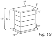
- Fig. 1G the box-shaped distribution units 10 are in the assembled state.
- the stack 14 of box-shaped distribution units 10 may, after having been brought to the assembled state, be handled in a variety of ways.
- the system 12 may be loaded directly into a cargo space of a vehicle for distribution, wherein the dimensions of the cargo space restricts decompression of the compressible acoustic panels 2 contained in the box-shaped distribution units 10, and thereby restricts the box-shaped distribution units 10 from being brought from the assembled state.
- the system 12 further comprises a securing member 20.
- the box-shaped distribution units 10 are configured to be secured by the securing member 20 in the assembled state.
- the securing member 20 may be provided in the form of a plastic film, as is shown in Fig. 1H .
- the plastic film is wrapped around the stack 14 of box-shaped distribution units 10 such that the box-shaped distribution units 10 are at least partially enclosed in the plastic film.
- the box-shaped distribution units 10 are completely enclosed by the plastic film.
- the first and second end plates 16, 18 are enclosed by the plastic film.
- the securing member 20 is provided in the form of a strap.
- the strap is arranged vertically along a longitudinal axis of stack of box-shaped distribution units 10 and around the box-shaped distribution units 10 such that the top part 6' of the uppermost box-shaped distribution unit 10' is restricted from moving away from the bottom part 3" of the lowermost box-shaped distribution unit 10".
- the end plates 16, 18 are configured for receiving the securing member 20. Furthermore, the end plates 16, 18 may be configured for receiving and releasably retaining the securing member 20. To this end, any end plate 16, 18 may e.g. be provided with a lug, or a slit, or a clamp for receiving a strap.
- the system 12 may be asssembled at a first location.
- the system 12 may subsequently be shipped to a second location different from the first location, wherein the system 12 is disassembled at the second location.
- a method of disassembling the system 12 is shown in Figs. 2A to 2C .
- the method comprises arranging the box-shaped distribution units 10 in the assembled state in a disassembly rack 22.
- the disassembly rack 24 comprises a plurality of vertical rails 24 configured to guide the box-shaped distribution units 10 during the bringing thereof from the assembled state. To this end, the vertical rails 24 of the rack 22 may be in contact with the stack 14 box-shaped distribution units 10 during decompression.
- the stack 14 may be in contact with any number of vertical rails 24.
- the rack 22, and thus the rails 24 thereof, is not in contact with the box-shaped distribution units 10.
- the box-shaped distribution units 10 may thus be arranged in the disassembly rack with a distance to each one of the vertical rails 24. The distance may e.g. be 1 cm, or 2 cm, or 3 cm.
- the box-shaped distribution units 10 are disassembled by an operator cutting the securing member 20 provided as a plastic film, as illustrated in Fig. 2A . Hence, bringing each box-shaped distribution unit 10 from the assembled state comprises releasing the securing member 20.
- Fig. 2B the securing member 20 has been released.
- pressure from the compressed stacks 1 of acoustic panels 2 are released when the securing member 20 is released such that the box-shaped distribution units 10 are brought to disassembled state, as is illustrated in Fig. 2C .
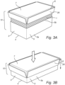
- each side wall portion 8 of the top part 6 may be provided with a respective flap portion 26.
- This enables the provision of side wall portions of smaller dimension such that the top part and the bottom part defines a box volume having a box height smaller than h1.
- the flap portions 26, prior to pressing of the top part 6 towards the bottom part 3 are folded towards and arranged against each the respective side wall portion 8.
- the pressing of the top part 6 towards the bottom part 3A is shown in Fig. 3B .
- Fig. 3B As is seen in Fig.
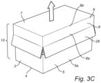
- the flap portions 26 prior to being brought to the assembled state, or after having been brought from the assembled state to a disassembled state, the flap portions 26 are arranged against the stack so as to protect the stack from contaminants, such as dust.
- the side wall portions 8 of the top part 6 are of smaller dimension such that the top part and the bottom part defines a box volume having a box height smaller than h1. Consequently, a larger extent of compression of the stack of compressible panels 1 is facilitated, while the box-shaped distribution unit 10 still retains the protective properties.
Landscapes
- Engineering & Computer Science (AREA)
- Mechanical Engineering (AREA)
- Packaging Of Annular Or Rod-Shaped Articles, Wearing Apparel, Cassettes, Or The Like (AREA)
- Stackable Containers (AREA)
Abstract
Description
- The present invention relates to a method and a system for handling compressible acoustic panels.
- Panels of mineral fiber material, such as glass wool, are used for their sound dampening properties. To this end, such acoustic panels are often arranged in or suspended from a ceiling.
- A challenge with distributing acoustic panels is packaging and transportation. A typical ceiling tile made of glass wool consists of 95 v% air, wheras the remaining 5 v% is glass wool fibres. Consequently, the majority of the transported volume is air, which is problem both from a cost perspective and an environmental perspective.
- Due to the compressible nature of such panels, a variety of solutions have been presented which entails reducing the volume of the panels during packaging and before transportation. Examples of solutions comprised in the state of the art can be found in
EP 2 460 738 B1EP 3 181 477 B1 - However, there exists some problems with the existing existing prior art solutions. For example, some solutions are practically challenging, thereby costly and/or time consuming. Furthermore, the securing member, which often is provided in the form of a plastic wrapping, may be penetrated during transportation, either unintentionally or intentionally. This leaves the panels exposed to damage or soiling. In some cases, it may lead to the panels being decompressed, thereby bursting through the wrapping and complicating further handling thereof.
- In view of the above, an object of the present invention is to provide a solution for handling compressible acoustic panels in a space efficient manner while improving the protection of the panels, thereby reducing soiling and damage of the panels.
- Another object is to provide a solution which is more cost efficient and/or time efficient.
- These and also other objects which will be evident from the following description are achieved by a method having the features defined in
claim 1 and a system having the features defined in claim 11. - According to a first aspect of the present invention, a method for handling compressible acoustic panels is provided, the method comprising: providing a plurality of compressible acoustic panels; providing at least two box-shaped distribution units, each box-shaped distribution unit comprising: a top part and a bottom part, wherein each box-shaped distribution unit is bringable to an assembled state in which one of the top part and the bottom part is inserted into the other of the top part and the bottom part for defining a box volume having a box height h1; for each box-shaped distribution unit, forming a stack comprising at least two compressible acoustic panels obtained from said plurality of compressible acoustic panels, wherein each stack has an uncompressed height h2 which is greater than box height h1; arranging each stack in the bottom part of the associated box-shaped distribution unit; arranging the top part of the associated box-shaped distribution unit on top of each stack; stacking the at least two box-shaped distribution units and the stacks of compressible acoustic panels contained therein; pressing the top part of the uppermost box-shaped distribution unit towards the bottom part of the lowermost box-shaped distribution unit for bringing each box-shaped distribution unit to the assembled state, thereby compressing the compressible acoustic panels contained in the box-shaped distribution units such that each stack has a compressed height of h1.
- According to a second aspect of the present invention, a system for handling compressible acoustic panels is provided, the system comprising: a plurality of compressible acoustic panels; at least two box-shaped distribution units, each box-shaped distribution unit comprising: a top part and a bottom part, wherein each box-shaped distribution unit is bringable to an assembled state in which one of the top part and the bottom part is inserted into the other of the top part and the bottom part for defining a box volume having a box height h1; and a securing member; wherein each box-shaped distribution unit is configured for receiving a stack comprising at least two compressible acoustic panels obtained from said plurality of compressible acoustic panels, wherein each stack has an uncompressed height h2 which is greater than box height h1; and the at least two box-shaped distribution units are configured to be stacked on top of each other and, in the assembled state, compress the compressible acoustic panels contained in the box-shaped distribution units such that each stack has a compressed height of h1, and wherein the at least two box-shaped distribution units are configured to be secured by the securing member in the assembled state.
- It is to be understood that any technical effect and benefit discussed in relation to the first aspect may be applicable to the second aspect, and vice versa.
- The compressible acoustic panels are protected by the box-shaped distribution units during packaging, such as during stacking the at least two box-shaped distribution units and pressing the top part of the uppermost box-shaped distribution unit towards the bottom part of the lowermost box-shaped distribution unit. Furthermore, the compressible acoustic panels are protected during further handling of the stack of box-shaped distribution units, especially during transportation thereof.
- Furthermore, since a plurality of box-shaped distribution units may be stacked on top of each other and pressed simultaneously, a more cost efficient and time efficient method is provided.
- A compressible acoustic panel may e.g. be made of mineral fiber material, such as mineral wool. However, it is to be understood that a compressible acoustic panel may be made of any other suitable material, or combination of suitable materials.
- A box-shaped distribution unit may e.g. be made of any material, for example cardboard or plastic. Stacking the at least two box-shaped distribution units may involve any practically feasible number of box-shaped distribution units, such as three, four, five or ten box-shaped distribution units. It is naturally to be understood that the number of box-shaped distribution units, in practice, is limited by any means of storing and/or transporting the box-shaped distribution units in the assembled state.
- The stack of box-shaped distribution units may, after having been brought to the assembled state, be handled in a variety of ways. For example, the stack may be loaded directly into a cargo space of a vehicle for distribution, wherein the dimensions of the cargo space restricts decompression of the compressible acoustic panels contained in the box-shaped distribution units, and thereby restricts the box-shaped distribution units from being brought from the the assembled state.
- The step of stacking may further comprise arranging the lowermost box-shaped distribution unit on a bottom end plate and arranging a top end plate on the uppermost box-shaped distribution unit.
- Hence, pressing the top part of the uppermost box-shaped distribution unit towards the bottom part of the lowermost box-shaped distribution unit may be facilitated by pressing the top end plate towards the bottom end plate. Hereby, a more uniform pressure distribution is facilitated, and the risk of damaging the box-shaped distribution units during pressing is reduced.
- Any end plate may further be configured for receiving and releasably retaining the securing member. To this end, any end plate may e.g. be provided with a lug for receiving a strap, or a slit for receiving a plastic film.
- The step of pressing the top part of the uppermost box-shaped distribution unit towards the bottom part of the lowermost box-shaped distribution may be performed at a first location, wherein the method may further comprise: shipping the box-shaped distribution units in the assembled state to a second location different from the first location; arranging the box-shaped distribution units in the assembled state in a disassembly rack at the second location, the disassembly rack comprising a plurality of vertical rails configured to guide the box-shaped distribution units during the bringing thereof from the assembled state; and bringing each box-shaped distribution unit from the assembled state, thereby decompressing the compressible acoustic panels contained in the box-shaped distribution units.
- It is to be understood that when the box-shaped distribution units are brought from the assembled state, the stacks of compressible acoustic panels contained therein regains the decompressed height of h2. The duration of decompression may e.g. be 10 s, or 20 s, or 30 s, depending on the properties of the acoustic panels and the box-shaped distribution units.
- That the disassembly rack guides the box-shaped distribution units during the bringing thereof from the assembled state is to be understood as the disassembly rack providing a physical perimeter so as to arrest the stack of one box-shaped distribution unit should it tilt during decompression of the compressible acoustic panels. To this end, the vertical rails of the rack may be in contact with the stack box-shaped distribution units during decompression. It is to be understood that the stack box-shaped distribution units may be in contact with any number of vertical rails. Alternatively, the rack is not in contact with the box-shaped distribution units. The box-shaped distribution units may thus be arranged in the disassembly rack with a distance to each one of the vertical rails. The distance may e.g. be 1 cm, or 2 cm, or 3 cm.
- The method may further comprise: providing a securing member; and securing the at least two box-shaped distribution units by the securing member in the assembled state.
- Hereby, the stack of box-shaped distribution units are restricted from being brought from the assembled state by the securing member. Thus, the box-shaped distribution units are easier to handle.
- Bringing each box-shaped distribution unit from the assembled state may further comprise releasing the securing member member.
- Hereby, pressure from the compressed stacks of acoustic panels are released when securing member released such that the box-shaped distribution units are brought to disassembled state.
- The securing member may e.g. be provided in the form of a strap. The strap is preferably arranged vertically along a longitudinal axis of stack of box-shaped distribution units and around the box-shaped distribution units such that the top part of the uppermost box-shaped distribution unit is restricted from moving away from the bottom part of the lowermost box-shaped distribution unit.
- Alternatively, the securing member may be provided in the form of a plastic film. The plastic film may be wrapped around the stack of box-shaped distribution units such that the box-shaped distribution units are at least partially enclosed in the plastic film. Alternatively, the box-shaped distribution units may be completely enclosed.
- In some embodiments, each box-shaped distribution unit is bringable to an assembled state in which the top part is inserted the bottom part. In some embodiments, each box-shaped distribution unit is bringable to an assembled state in which the bottom part is inserted into the top part. However, it is to be understood that a stack of box-shaped distribution unit may comprise at least one box-shaped distribution unit where the bottom part is inserted into the top part and at least one box-shaped distribution unit top part is inserted the bottom part.
- For each box-shaped distribution unit, the top part may form a space for receiving the bottom part such that the box-shaped distribution may be bringable to the assembled state in which the bottom part is inserted into the top part.
- Hereby, since the stacks of compressible acoustic panels are contained in the bottom parts, the box-shaped distribution units are more easily brought to the assembled state.
- For each box-shaped distribution unit, the top part may comprise a top wall portion and a plurality of side wall portions, wherein each side wall portion may have a respective first end portion connected to the top wall portion and a respective second end portion distal to the respective first end portion such that each side wall portion is arranged with a first extension perpendicular to a plane of extension of the top wall portion and parallel to the respective first extension of the other side wall portions of the plurality of side wall portions so as to form said space.
- The top part may comprise any number of side wall portions. The number of side wall portions is inter alia dependent on the shape of the top wall portion and/or the shape of the box-shaped distribution unit. For example, the top part may comprise three side wall portions, or four side wall portions. Preferably, the box-shaped distribution unit has a cuboid shape. More preferably, the box-shaped distribution unit may have a rectangular cuboid shape.
- For each top part, the plurality of side wall portions may comprise four side wall portions, wherein each side wall portion may adjoin two other side wall portions of the four side wall portions, wherein each side wall portion may have a second extension parallel to the plane of extension of the top wall portion and perpendicular to the respective second extension of each adjoining side wall portion.
- Hereby, each top part comprises a respective first side wall portion, second side wall portion, third side wall portion and fourth side wall portion, wherein the first side wall portion adjoins the second side wall portion and the fourth side wall portion, and the second side wall portion adjoins the first side wall portion and the third wall portion, and the third wall portion adjoins the second wall portion and the fourth wall portion, and the fourth wall portion adjoins the third wall portion and the first wall portion.
- Each side wall portion may be provided with a respective flap portion, wherein the step of pressing further comprises folding each flap portion towards and arranging each flap portion against the respective side wall portion.
- Prior to being brought to the assembled state, when the top part is arranged on the stack of compressible panels arranged in the corresponding bottom part, the flap portions may be arranged against the stack so as to protect the stack from contaminants, such as dust. This enables the provision of side wall portions of smaller dimension such that the top part and the bottom part defines a box volume having a box height smaller than h1. Consequently, upon folding each flap portion towards and arranging each flap portion against the respective side wall portion, a larger extent of compression of the compressible panels is facilitated. Hereby, an even more space-efficient method is provided.
- The system may further comprise a bottom end plate and a top end plate, wherein the bottom end plate is configured to be arranged such that a lowermost box-shaped distribution unit of a stack of box-shaped distribution is arranged on the bottom end plate, and wherein the top end plate is configured to be arranged on an uppermost box-shaped distribution unit of a stack of box-shaped distribution units.
- Thus, stacking the at least two box-shaped distribution units may further comprise arranging the lowermost box-shaped distribution unit of a stack of box-shaped distribution units on a bottom end plate and arranging a top end plate on the uppermost box-shaped distribution unit of the stack of box-shaped distribution units.
- Hereby, the pressure on the box-shaped distribution units while being pressed may be more evenly distributed.
- These and other embodiments of the present invention will now be described in more detail, with reference to the appended drawings showing exemplary embodiments of the present invention, wherein:
-
Fig.1A is a perspective view of a stack of compressible acoustic panels; -
Fig. 1B is a perspective view of the stack ofFig. 1A arranged in a bottom part of a box-shaped distribution unit; -
Fig. 1C is a perspective view of the stack and the bottom part ofFig. 1B , further showing the arranging of a top part of a box-shaped distribution unit on top of the stack; -
Fig. 1D is a perspective view of the stack and the bottom part ofFig. 1c when the top part is arranged on top of the stack; -
Fig. 1E is a perspective view of a stack of box-shaped distribution units arranged between a top end plate and a bottom end plate; -
Fig. 1F is a perspective view of the stack ofFig. 1E while being compressed; -
Fig. 1G is a perspective view of compressed a stack of box-shaped distribution units; -
Fig. 1H is a perspective view of a compressed stack of box-shaped distribution units provided with a securing member in the form of a plastic film; -
Fig. 1I is a perspective view of a compressed stack of box-shaped distribution units provided with a securing member in the form of straps; -
Fig. 2A is a perspective view of a stack of box-shaped distribution units provided with a securing member and arranged in a disassembly rack; -
Fig. 2B is a perspective view of the stack inFig. 2A , wherein the securing member has been released; -
Fig. 2C is a perspective view of the stack inFig. 2B , wherein each box-shaped distribution unit is in a disassembled state in which the stacks of compressible acoustic panels are in a decompressed state; -
Fig. 3A is a perspective view of a box-shaped distribution unit, wherein the top part is provided with flap portions; -
Fig. 3B is a perspective view of the box-shaped distribution unit inFig. 3A while being compressed; and -
Fig. 3C is a perspective view of the of the box-shaped distribution unit inFig. 3B while being decompressed. - In the following detailed description, some embodiments of the present invention will be described. However, it is to be understood that features of the different embodiments are exchangeable between the embodiments and may be combined in different ways, unless anything is specifically indicated. Even though in the following description, numerous details are set forth to provide a more thorough understanding of the present invention, it will be apparent to one skilled in the art that the present invention may be practiced without these details. In other instances, well known constructions or functions are not described in detail, so as not to obscure the present invention.
-
Fig. 1A is a perspective view of astack 1 of compressibleacoustic panels 2. Any one compressibleacoustic panel 2 may e.g. be made of mineral fiber material, such as mineral wool. However, it is to be understood that a compressibleacoustic panel 2 may be made of any other suitable material, or combination of suitable materials. Furthermore, theacoustic panels 2 may have any shape. For example, anacoustic panel 2 may be circular, oblong, or polygonal. Preferably, as is also shown inFig. 1A , eachacoustic panel 2 has rectangular cuboid shape. Thestack 1 has a height h2. The height h2 is the height of thestack 1 when each compressibleacoustic panel 2 is in an uncompressed state. -
Fig. 1B is a perspective view of thestack 1 arranged in abottom part 3 of a box-shaped distribution unit 10 (shown inFig. 1D ). A box-shapeddistribution unit 10, and thereby thebottom part 3 and/or top part 6 (shown inFig. 1C ) thereof, may e.g. be made of any suitable material, such as cardboard or plastic. Thebottom part 3, corresponding to the shape of eachacoustic panel 2, has a rectangular cuboid shape. Thebottom part 3 comprises abottom wall portion 4 and a plurality ofside wall portions 5. Here, thebottom part 3 comprises fourside wall portions 5, wherein a firstside wall portion 5 adjoins the secondside wall portion 5 and the fourthside wall portion 5, and the secondside wall portion 5 adjoins the firstside wall portion 5 and the thirdside wall portion 5, and the thirdside wall portion 5 adjoins the secondside wall portion 5 and the fourthside wall portion 5, and the fourthside wall portion 5 adjoins the thirdside wall portion 5 and the firstside wall portion 5. Furthermore, eachside wall portion 5 comprises a respectivefirst end portion 5a connected to thebottom wall portion 4 and a respectivesecond end portion 5b distal to the respectivefirst end portion 5a such that eachside wall portion 5 is arranged with a first extension perpendicular to a plane of extension of thebottom wall portion 4 and parallel to the respective first extension of the otherside wall portions 5. Hereby, a space for receiving thestack 1 of compressibleacoustic panels 2 is formed. - Even though
Fig. 1A illustrates asingle stack 1 of compressibleacoustic panels 2 contained in thebottom part 3, it is to be understood that more than onestack 1 may be contained in thebottom part 3. For example, thebottom part 3 may be provided with a first and asecond stack 1 arranged next to each other. Thus, it is to be understood thatmultiple stacks 1 may be arranged in thebottom part 3 and next to each other, and that this number is limited by the relative dimensions of theacoustic panels 2 comprised in thestacks 1 and thebottom part 3. - In
Fig. 1C , arranging of atop part 6 of a box-shapeddistribution unit 10 on top of thestack 2 is shown. Corresponding to the shape of thebottom part 3, thetop part 6 has a rectangular cuboid shape. Thetop part 6 comprises atop wall portion 7 and a plurality ofside wall portions 8. Here, thetop part 6 comprises fourside wall portions 8, wherein a firstside wall portion 8 adjoins the secondside wall portion 8 and the fourthside wall portion 8, and the secondside wall portion 8 adjoins the firstside wall portion 8 and the thirdside wall portion 8, and the thirdside wall portion 8 adjoins the secondside wall portion 8 and the fourthside wall portion 8, and the fourthside wall portion 8 adjoins the thirdside wall portion 8 and the firstside wall portion 8. Furthermore, eachside wall portion 8 comprises a respectivefirst end portion 8a connected to thetop wall portion 7 and a respectivesecond end portion 8b distal to the respectivefirst end portion 8a such that eachside wall portion 8 is arranged with a first extension perpendicular to a plane of extension of thetop wall portion 7 and parallel to the respective first extension of the otherside wall portions 8. Hereby, a space for receiving thebottom part 3 containing thestack 1 of compressibleacoustic panels 2 is formed. Hereby, the dimensions of thetop part 6 are larger than that of thebottom part 3. That is, the length of aside wall portion 8 of thetop part 6 is larger than a length of aside wall portion 5 of thebottom part 3. Consequently, the total area of an inwards facing surface of thetop wall portion 7 is larger than that of an inwards facing surface of thebottom wall portion 4 of thebottom part 3, and the total area of an outwards facingsurface 2a of the compressibleacoustic panels 2. -
Fig. 1D shows thetop part 6 when arranged on thestack 1 of compressibleacoustic panels 2. Here, the box-shapeddistribution unit 10 is in an unassembled state. Thetop part 6 of the box-shapeddistribution unit 10 thus covers at least a majority of thestack 1 not covered by thebottom part 3. Here, theside wall portions 8 of thetop part 6 of the box-shapeddistribution unit 10 further covers at least a majority of the outwards facing side surfaces of thestack 1 of compressibleacoustic panels 2. Hereby, thestack 1 is protected during storage also when the box-shapeddistribution unit 10 is not in an assembled state. - In
Fig. 1E , asystem 12 for handling compressibleacoustic panels 1 is shown. The system comprises astack 14 of box-shapeddistribution units 10. Here, thestack 14 comprises four box-shapeddistribution units 10. However, it is to be understood that thestack 14 may comprise any number of box-shapeddistribution units 10. It is furthermore to be understood that the number of box-shapeddistribution units 10, in practice, is limited by any means of storing and/or transporting the box-shapeddistribution units 10 in the assembled state. Here, each box-shapeddistribution unit 10 is in an unassembled state, and therefore, eachrespective stack 1 of compressible acoustic panels contained in each box-shaped distribution unit are in an uncompressed state. - The
system 12 further comprises abottom end plate 18 and atop end plate 16. The lowermost box-shapeddistribution unit 10" of thestack 14 of box-shapeddistribution units 10 is arranged on thebottom end plate 18, and thetop end plate 16 is arranged on the uppermost box-shapeddistribution unit 10'. - In
Fig. 1F , the bringing of the box-shapeddistribution units 10 to an assembled state is illustrated. Here, each box-shapeddistribution unit 10 is bringable to an assembled state in which thebottom part 3 is inserted into thetop part 6 for defining a box volume having a box height h1. The top part 6' of the uppermost box-shapeddistribution unit 10' is here pressed towards thebottom part 3" of the lowermost box-shapeddistribution unit 10", thereby bringing each box-shapeddistribution unit 10 to the assembled state. Hereby, the stack of box-shapeddistribution units 10 define a compression axis along a longitudinal axis of thestack 14, as illustrated by the arrow inFig. 1F . Bringing each box-shapeddistribution unit 10 to the assembled state compresses the compressibleacoustic panels 2 contained in the box-shapeddistribution units 10 such that eachstack 1 has a compressed height of h1. Here, pressing the top part 6' of the uppermost box-shapeddistribution unit 10' towards thebottom part 3" of the lowermost box-shapeddistribution unit 10" is facilitated by pressing thetop end plate 16 towards thebottom end plate 18. - In
Fig. 1G , the box-shapeddistribution units 10 are in the assembled state. - The
stack 14 of box-shapeddistribution units 10 may, after having been brought to the assembled state, be handled in a variety of ways. For example, thesystem 12 may be loaded directly into a cargo space of a vehicle for distribution, wherein the dimensions of the cargo space restricts decompression of the compressibleacoustic panels 2 contained in the box-shapeddistribution units 10, and thereby restricts the box-shapeddistribution units 10 from being brought from the assembled state. - Preferably, the
system 12 further comprises a securingmember 20. The box-shapeddistribution units 10 are configured to be secured by the securingmember 20 in the assembled state. The securingmember 20 may be provided in the form of a plastic film, as is shown inFig. 1H . The plastic film is wrapped around thestack 14 of box-shapeddistribution units 10 such that the box-shapeddistribution units 10 are at least partially enclosed in the plastic film. Here, the box-shapeddistribution units 10 are completely enclosed by the plastic film. Furthermore, the first andsecond end plates member 20 is provided in the form of a strap. The strap is arranged vertically along a longitudinal axis of stack of box-shapeddistribution units 10 and around the box-shapeddistribution units 10 such that the top part 6' of the uppermost box-shapeddistribution unit 10' is restricted from moving away from thebottom part 3" of the lowermost box-shapeddistribution unit 10". Theend plates member 20. Furthermore, theend plates member 20. To this end, anyend plate - The
system 12 may be asssembled at a first location. Thesystem 12 may subsequently be shipped to a second location different from the first location, wherein thesystem 12 is disassembled at the second location. A method of disassembling thesystem 12 is shown inFigs. 2A to 2C . The method comprises arranging the box-shapeddistribution units 10 in the assembled state in adisassembly rack 22. Thedisassembly rack 24 comprises a plurality ofvertical rails 24 configured to guide the box-shapeddistribution units 10 during the bringing thereof from the assembled state. To this end, thevertical rails 24 of therack 22 may be in contact with thestack 14 box-shapeddistribution units 10 during decompression. It is to be understood that thestack 14 may be in contact with any number ofvertical rails 24. Alternatively, therack 22, and thus therails 24 thereof, is not in contact with the box-shapeddistribution units 10. The box-shapeddistribution units 10 may thus be arranged in the disassembly rack with a distance to each one of the vertical rails 24. The distance may e.g. be 1 cm, or 2 cm, or 3 cm. - Here, the box-shaped
distribution units 10 are disassembled by an operator cutting the securingmember 20 provided as a plastic film, as illustrated inFig. 2A . Hence, bringing each box-shapeddistribution unit 10 from the assembled state comprises releasing the securingmember 20. - In
Fig. 2B , the securingmember 20 has been released. Hereby, pressure from thecompressed stacks 1 ofacoustic panels 2 are released when the securingmember 20 is released such that the box-shapeddistribution units 10 are brought to disassembled state, as is illustrated inFig. 2C . - An alternative of the box-shaped
distribution unit 10 is illustrated inFigs. 3A to 3C . InFig. 3A , eachside wall portion 8 of thetop part 6 may be provided with arespective flap portion 26. This enables the provision of side wall portions of smaller dimension such that the top part and the bottom part defines a box volume having a box height smaller than h1. Here, theflap portions 26, prior to pressing of thetop part 6 towards thebottom part 3, are folded towards and arranged against each the respectiveside wall portion 8. The pressing of thetop part 6 towards the bottom part 3A is shown inFig. 3B . As is seen inFig. 3C , prior to being brought to the assembled state, or after having been brought from the assembled state to a disassembled state, theflap portions 26 are arranged against the stack so as to protect the stack from contaminants, such as dust. Hereby, as may be appreciated fromFig. 3A and 3B , theside wall portions 8 of thetop part 6 are of smaller dimension such that the top part and the bottom part defines a box volume having a box height smaller than h1. Consequently, a larger extent of compression of the stack ofcompressible panels 1 is facilitated, while the box-shapeddistribution unit 10 still retains the protective properties.
Claims (15)
- A method for handling compressible acoustic panels (2), the method comprising:providing a plurality of compressible acoustic panels (2);providing at least two box-shaped distribution units (10), each box-shaped distribution unit (10) comprising: a top part (6) and a bottom part (3), wherein each box-shaped distribution unit (10) is bringable to an assembled state in which one of the top part (6) and the bottom part (3) is inserted into the other of the top part (6) and the bottom part (3) for defining a box volume having a box height h1;for each box-shaped distribution unit (10), forming a stack (1) comprising at least two compressible acoustic panels (2) obtained from said plurality of compressible acoustic panels (2), wherein each stack (1) has an uncompressed height h2 which is greater than box height h1;arranging each stack (1) in the bottom part of the associated box-shaped distribution unit (10);arranging the top part (6) of the associated box-shaped distribution unit on top of each stack (1);stacking the at least two box-shaped distribution units (10) and the stacks (1) of compressible acoustic panels (2) contained therein;pressing the top part (6') of the uppermost box-shaped distribution unit (10') towards the bottom part (3") of the lowermost box-shaped distribution unit (10") for bringing each box-shaped distribution unit (10) to the assembled state, thereby compressing the compressible acoustic panels (2) contained in the box-shaped distribution units (10) such that each stack (1) has a compressed height of h1.
- The method according to claim 1, further comprising:providing a securing member (20); andsecuring the at least two box-shaped distribution units (10) by the securing member (20) in the assembled state.
- The method according to claim 1 or 2, wherein for each box-shaped distribution unit (10), the top part (6) forms a space for receiving the bottom part (3) such that the box-shaped distribution (10) is bringable to the assembled state in which the bottom part (3) is inserted into the top part (6).
- The method according to claim 3, wherein for each box-shaped distribution unit (10), the top part (6) comprises a top wall portion (7) and a plurality of side wall portions (8), wherein each side wall portion (8) has a respective first end portion (8b) connected to the top wall portion (7) and a respective second end portion (8a) distal to said respective first end portion (8b) such that each side wall portion (8) is arranged with a first extension perpendicular to a plane of extension of the top wall portion (7) and parallel to the respective first extension of the other side wall portions (8) of the plurality of side wall portions (8) so as to form said space.
- The method according to claim 4, wherein each top part (6) comprises four side wall portions (8), wherein each side wall portion (8) adjoins two other side wall portions (8) of the four side wall portions (8) and has a second extension parallel to the plane of extension of the top wall portion (7) and perpendicular to the respective second extension of each adjoining side wall portion (8).
- The method according to claim 4 or 5, wherein each side wall portion (8) is provided with a respective flap portion (26), wherein the step of pressing further comprises folding each flap portion (26) towards and arranging each flap portion (26) against the respective side wall portion (8).
- The method according to any one of the preceding claim,
wherein the step of pressing the top part (6') of the uppermost box-shaped distribution unit (10') towards the bottom part (3") of the lowermost box-shaped distribution unit (10") is performed at a first location, wherein the method further comprises:shipping the box-shaped distribution units (10) in the assembled state to a second location different from the first location;arranging the box-shaped distribution units (10) in the assembled state in a disassembly rack (22) at the second location, the disassembly rack (22) comprising a plurality of vertical rails (24) configured to guide the box-shaped distribution units (10) during the bringing thereof from the assembled state; andbringing each box-shaped distribution (10) unit from the assembled state, thereby decompressing the compressible acoustic panels (2) contained in the box-shaped distribution units (10). - The method according to claim 7 when dependent on at least claim 2, wherein bringing each box-shaped distribution unit (10) from the assembled state further comprises releasing the securing member member (20).
- The method according to any one of the preceding claims,
wherein stacking the at least two box-shaped distribution units further comprises arranging the lowermost box-shaped distribution unit (10") of a stack (14) of box-shaped distribution units (10) on a bottom end plate (18) and arranging a top end plate (16) on the uppermost box-shaped distribution unit (10') of the stack (14) of box-shaped distribution units (10). - A system (12) for handling compressible acoustic panels (2), the system (12) comprising:a plurality of compressible acoustic panels (2);at least two box-shaped distribution units (10), each box-shaped distribution unit (10) comprising: a top part (6) and a bottom part (3), wherein each box-shaped distribution unit (10) is bringable to an assembled state in which one of the top part (6) and the bottom part (3) is inserted into the other of the top part (6) and the bottom part (3) for defining a box volume having a box height h1; anda securing member (20); whereineach box-shaped distribution unit (10) is configured for receiving a stack (1) comprising at least two compressible acoustic panels (2) obtained from said plurality of compressible acoustic panels (2), wherein each stack has an uncompressed height h2 which is greater than box height h1; andthe at least two box-shaped distribution units (10) are configured to be stacked on top of each other and, in the assembled state, compress the compressible acoustic panels (2) contained in the box-shaped distribution units such that each stack (1) has a compressed height of h1, and wherein the at least two box-shaped distribution units (10) are configured to be secured by the securing member (20) in the assembled state.
- The system (12) according to claim 9, wherein the securing member (20) is provided in the form of a strap or a plastic film.
- The system (12) according to claim 9, 10 or 11, wherein for each box-shaped distribution unit (10), the top part (6) forms a space for receiving the bottom part (3) such that the box-shaped distribution unit (10) is bringable to the assembled state in which the bottom part (3) is inserted into the top part (6), and wherein for each box-shaped distribution unit (10), the top part (6) comprises a top wall portion (7) and a plurality of side wall portions (8), wherein each side wall portion (8) has a respective first end portion (8b) connected to the top wall portion (7) and a respective second end portion (8a) distal to said respective first end portion (8b) such that each side wall portion (8) is arranged with a first extension perpendicular to a plane of extension of the top wall portion (7) and parallel to the respective first extension of the other side wall portions (8) of the plurality of side wall portions (8) so as to form said space.
- The system (12) according to claim 12, wherein, each top part (6) comprises four side wall portions (8), wherein each side wall portion (8) adjoins two other side wall portions (8) of the four side wall portions (8), wherein each side wall portion (8)has a second extension parallel to the plane of extension of the top wall portion (7) and perpendicular to the respective second extension of each adjoining side wall portion (8).
- The system (12) according to claim 12 or 13, wherein each side wall portion (8) is provided with a respective flap portion (26) configured to be folded towards and arranged against the respective side wall portion (8).
- The system (12) according to any one of claims 10-14, further comprising a bottom end plate (18) and a top end plate (16), wherein the bottom end plate (18) is configured to be arranged such that a lowermost box-shaped distribution unit (10") of a stack (14) of box-shaped distribution units (10) is arranged on the bottom end plate (18), and wherein the top end plate (16) is configured to be arranged on an uppermost box-shaped distribution unit (10') of a stack (14) of box-shaped distribution units (10).
Priority Applications (2)
| Application Number | Priority Date | Filing Date | Title |
|---|---|---|---|
| EP23168662.7A EP4450422B1 (en) | 2023-04-19 | 2023-04-19 | Method and system for handling compressible acoustic panels |
| PCT/EP2024/060742 WO2024218312A1 (en) | 2023-04-19 | 2024-04-19 | Method and system for handling compressible acoustic panels |
Applications Claiming Priority (1)
| Application Number | Priority Date | Filing Date | Title |
|---|---|---|---|
| EP23168662.7A EP4450422B1 (en) | 2023-04-19 | 2023-04-19 | Method and system for handling compressible acoustic panels |
Publications (3)
| Publication Number | Publication Date |
|---|---|
| EP4450422A1 true EP4450422A1 (en) | 2024-10-23 |
| EP4450422C0 EP4450422C0 (en) | 2026-01-14 |
| EP4450422B1 EP4450422B1 (en) | 2026-01-14 |
Family
ID=86096064
Family Applications (1)
| Application Number | Title | Priority Date | Filing Date |
|---|---|---|---|
| EP23168662.7A Active EP4450422B1 (en) | 2023-04-19 | 2023-04-19 | Method and system for handling compressible acoustic panels |
Country Status (2)
| Country | Link |
|---|---|
| EP (1) | EP4450422B1 (en) |
| WO (1) | WO2024218312A1 (en) |
Citations (3)
| Publication number | Priority date | Publication date | Assignee | Title |
|---|---|---|---|---|
| WO2005070772A1 (en) * | 2004-01-14 | 2005-08-04 | Kimberly-Clark Worldwide, Inc. | Package for compressible products |
| EP2460738B1 (en) | 2010-12-03 | 2016-03-16 | Saint-Gobain Ecophon AB | Method for providing a transport unit, a transport unit |
| EP3181477B1 (en) | 2015-08-19 | 2018-11-07 | Saint-Gobain Ecophon AB | Transport unit for compressible ceiling tiles |
Family Cites Families (3)
| Publication number | Priority date | Publication date | Assignee | Title |
|---|---|---|---|---|
| US2574384A (en) * | 1948-11-01 | 1951-11-06 | Gaylord Container Corp | Carton with automatic cover locking means |
| US2610783A (en) * | 1950-11-09 | 1952-09-16 | Ochar Thomas | Self-locking box |
| EP0571711B1 (en) * | 1992-05-26 | 1996-05-15 | Beiersdorf Aktiengesellschaft | Folded box with hooded lid |
-
2023
- 2023-04-19 EP EP23168662.7A patent/EP4450422B1/en active Active
-
2024
- 2024-04-19 WO PCT/EP2024/060742 patent/WO2024218312A1/en not_active Ceased
Patent Citations (3)
| Publication number | Priority date | Publication date | Assignee | Title |
|---|---|---|---|---|
| WO2005070772A1 (en) * | 2004-01-14 | 2005-08-04 | Kimberly-Clark Worldwide, Inc. | Package for compressible products |
| EP2460738B1 (en) | 2010-12-03 | 2016-03-16 | Saint-Gobain Ecophon AB | Method for providing a transport unit, a transport unit |
| EP3181477B1 (en) | 2015-08-19 | 2018-11-07 | Saint-Gobain Ecophon AB | Transport unit for compressible ceiling tiles |
Also Published As
| Publication number | Publication date |
|---|---|
| WO2024218312A1 (en) | 2024-10-24 |
| EP4450422C0 (en) | 2026-01-14 |
| EP4450422B1 (en) | 2026-01-14 |
Similar Documents
| Publication | Publication Date | Title |
|---|---|---|
| US7802527B2 (en) | Pallet | |
| KR100528304B1 (en) | Rolled article storing and transporting container | |
| NO158864B (en) | PROCEDURE FOR CONDITIONING COMPRESSABLE PLATES. | |
| US5803257A (en) | Panel crating structure | |
| JP4544848B2 (en) | Casing for holding solar panel | |
| EP4450422B1 (en) | Method and system for handling compressible acoustic panels | |
| CA2238157C (en) | Cable tray packaging | |
| US11186410B2 (en) | Flexible dynamic packaging of product entities | |
| US6269951B1 (en) | Packing system for unit loads | |
| US5139145A (en) | Adjustable load cover for use with various sizes of rectangularly topped stacks of palletized material | |
| US6098804A (en) | Metal packaging structure for a bundle of panels | |
| US3137388A (en) | Shipping apparatus | |
| EP1309493B1 (en) | Transport unit for rock wool products, in particular rock wool insulation panels, arranged in a stack | |
| JP3343744B2 (en) | Buffer packaging assembly | |
| EP4043359A1 (en) | Pallet foot | |
| US5042665A (en) | Packaging frame | |
| US5984101A (en) | Shipping protector | |
| US3206050A (en) | Rigid crating system for sheet material and the like | |
| US6264410B1 (en) | Shipping container system for stabilizing flexible loads | |
| EP3632827A1 (en) | Cable reel with barrel storage | |
| JP2022037899A (en) | Film reel assembly pack | |
| JP2019123535A (en) | Packing box and packing method | |
| US5823343A (en) | Packaging apparatus | |
| JP2003292028A (en) | Packing method of battery separator sheet roll | |
| JP2002255107A (en) | Battery separator roll product packing method |
Legal Events
| Date | Code | Title | Description |
|---|---|---|---|
| PUAI | Public reference made under article 153(3) epc to a published international application that has entered the european phase |
Free format text: ORIGINAL CODE: 0009012 |
|
| STAA | Information on the status of an ep patent application or granted ep patent |
Free format text: STATUS: THE APPLICATION HAS BEEN PUBLISHED |
|
| AK | Designated contracting states |
Kind code of ref document: A1 Designated state(s): AL AT BE BG CH CY CZ DE DK EE ES FI FR GB GR HR HU IE IS IT LI LT LU LV MC ME MK MT NL NO PL PT RO RS SE SI SK SM TR |
|
| STAA | Information on the status of an ep patent application or granted ep patent |
Free format text: STATUS: REQUEST FOR EXAMINATION WAS MADE |
|
| 17P | Request for examination filed |
Effective date: 20250410 |
|
| GRAP | Despatch of communication of intention to grant a patent |
Free format text: ORIGINAL CODE: EPIDOSNIGR1 |
|
| STAA | Information on the status of an ep patent application or granted ep patent |
Free format text: STATUS: GRANT OF PATENT IS INTENDED |
|
| RIC1 | Information provided on ipc code assigned before grant |
Ipc: B65D 85/07 20170101AFI20250820BHEP Ipc: B65D 85/62 20060101ALI20250820BHEP Ipc: B65B 63/02 20060101ALI20250820BHEP Ipc: B65B 35/50 20060101ALI20250820BHEP |
|
| INTG | Intention to grant announced |
Effective date: 20250902 |
|
| GRAS | Grant fee paid |
Free format text: ORIGINAL CODE: EPIDOSNIGR3 |
|
| GRAA | (expected) grant |
Free format text: ORIGINAL CODE: 0009210 |
|
| STAA | Information on the status of an ep patent application or granted ep patent |
Free format text: STATUS: THE PATENT HAS BEEN GRANTED |
|
| AK | Designated contracting states |
Kind code of ref document: B1 Designated state(s): AL AT BE BG CH CY CZ DE DK EE ES FI FR GB GR HR HU IE IS IT LI LT LU LV MC ME MK MT NL NO PL PT RO RS SE SI SK SM TR |
|
| REG | Reference to a national code |
Ref country code: CH Ref legal event code: F10 Free format text: ST27 STATUS EVENT CODE: U-0-0-F10-F00 (AS PROVIDED BY THE NATIONAL OFFICE) Effective date: 20260114 Ref country code: GB Ref legal event code: FG4D |
|
| REG | Reference to a national code |
Ref country code: DE Ref legal event code: R096 Ref document number: 602023010617 Country of ref document: DE |
|
| REG | Reference to a national code |
Ref country code: IE Ref legal event code: FG4D |
|
| U01 | Request for unitary effect filed |
Effective date: 20260205 |
|
| U07 | Unitary effect registered |
Designated state(s): AT BE BG DE DK EE FI FR IT LT LU LV MT NL PT RO SE SI Effective date: 20260211 |
|
| U1N | Appointed representative for the unitary patent procedure changed after the registration of the unitary effect |
Representative=s name: AWA SWEDEN AB; SE |
|
| U20 | Renewal fee for the european patent with unitary effect paid |
Year of fee payment: 4 Effective date: 20260318 |
|
| PG25 | Lapsed in a contracting state [announced via postgrant information from national office to epo] |
Ref country code: RS Free format text: LAPSE BECAUSE OF FAILURE TO SUBMIT A TRANSLATION OF THE DESCRIPTION OR TO PAY THE FEE WITHIN THE PRESCRIBED TIME-LIMIT Effective date: 20260414 |
|
| PG25 | Lapsed in a contracting state [announced via postgrant information from national office to epo] |
Ref country code: ES Free format text: LAPSE BECAUSE OF FAILURE TO SUBMIT A TRANSLATION OF THE DESCRIPTION OR TO PAY THE FEE WITHIN THE PRESCRIBED TIME-LIMIT Effective date: 20260114 |
|
| PG25 | Lapsed in a contracting state [announced via postgrant information from national office to epo] |
Ref country code: PL Free format text: LAPSE BECAUSE OF FAILURE TO SUBMIT A TRANSLATION OF THE DESCRIPTION OR TO PAY THE FEE WITHIN THE PRESCRIBED TIME-LIMIT Effective date: 20260114 |
|
| PG25 | Lapsed in a contracting state [announced via postgrant information from national office to epo] |
Ref country code: GR Free format text: LAPSE BECAUSE OF FAILURE TO SUBMIT A TRANSLATION OF THE DESCRIPTION OR TO PAY THE FEE WITHIN THE PRESCRIBED TIME-LIMIT Effective date: 20260415 |
|
| PG25 | Lapsed in a contracting state [announced via postgrant information from national office to epo] |
Ref country code: NO Free format text: LAPSE BECAUSE OF FAILURE TO SUBMIT A TRANSLATION OF THE DESCRIPTION OR TO PAY THE FEE WITHIN THE PRESCRIBED TIME-LIMIT Effective date: 20260414 |
|
| PG25 | Lapsed in a contracting state [announced via postgrant information from national office to epo] |
Ref country code: HR Free format text: LAPSE BECAUSE OF FAILURE TO SUBMIT A TRANSLATION OF THE DESCRIPTION OR TO PAY THE FEE WITHIN THE PRESCRIBED TIME-LIMIT Effective date: 20260114 |
|
| PG25 | Lapsed in a contracting state [announced via postgrant information from national office to epo] |
Ref country code: IS Free format text: LAPSE BECAUSE OF FAILURE TO SUBMIT A TRANSLATION OF THE DESCRIPTION OR TO PAY THE FEE WITHIN THE PRESCRIBED TIME-LIMIT Effective date: 20260514 |