EP4450420A1 - Content container - Google Patents
Content container Download PDFInfo
- Publication number
- EP4450420A1 EP4450420A1 EP23767116.9A EP23767116A EP4450420A1 EP 4450420 A1 EP4450420 A1 EP 4450420A1 EP 23767116 A EP23767116 A EP 23767116A EP 4450420 A1 EP4450420 A1 EP 4450420A1
- Authority
- EP
- European Patent Office
- Prior art keywords
- container
- discharging
- content
- outlet
- discharging part
- Prior art date
- Legal status (The legal status is an assumption and is not a legal conclusion. Google has not performed a legal analysis and makes no representation as to the accuracy of the status listed.)
- Pending
Links
Images



Classifications
-
- B—PERFORMING OPERATIONS; TRANSPORTING
- B65—CONVEYING; PACKING; STORING; HANDLING THIN OR FILAMENTARY MATERIAL
- B65D—CONTAINERS FOR STORAGE OR TRANSPORT OF ARTICLES OR MATERIALS, e.g. BAGS, BARRELS, BOTTLES, BOXES, CANS, CARTONS, CRATES, DRUMS, JARS, TANKS, HOPPERS, FORWARDING CONTAINERS; ACCESSORIES, CLOSURES, OR FITTINGS THEREFOR; PACKAGING ELEMENTS; PACKAGES
- B65D35/00—Pliable tubular containers adapted to be permanently or temporarily deformed to expel contents, e.g. collapsible tubes for toothpaste or other plastic or semi-liquid material; Holders therefor
- B65D35/44—Closures
- B65D35/46—Closures with valves
-
- A—HUMAN NECESSITIES
- A45—HAND OR TRAVELLING ARTICLES
- A45D—HAIRDRESSING OR SHAVING EQUIPMENT; EQUIPMENT FOR COSMETICS OR COSMETIC TREATMENTS, e.g. FOR MANICURING OR PEDICURING
- A45D34/00—Containers or accessories specially adapted for handling liquid toiletry or cosmetic substances, e.g. perfumes
-
- A—HUMAN NECESSITIES
- A45—HAND OR TRAVELLING ARTICLES
- A45D—HAIRDRESSING OR SHAVING EQUIPMENT; EQUIPMENT FOR COSMETICS OR COSMETIC TREATMENTS, e.g. FOR MANICURING OR PEDICURING
- A45D40/00—Casings or accessories specially adapted for storing or handling solid or pasty toiletry or cosmetic substances, e.g. shaving soaps or lipsticks
-
- B—PERFORMING OPERATIONS; TRANSPORTING
- B65—CONVEYING; PACKING; STORING; HANDLING THIN OR FILAMENTARY MATERIAL
- B65D—CONTAINERS FOR STORAGE OR TRANSPORT OF ARTICLES OR MATERIALS, e.g. BAGS, BARRELS, BOTTLES, BOXES, CANS, CARTONS, CRATES, DRUMS, JARS, TANKS, HOPPERS, FORWARDING CONTAINERS; ACCESSORIES, CLOSURES, OR FITTINGS THEREFOR; PACKAGING ELEMENTS; PACKAGES
- B65D43/00—Lids or covers for rigid or semi-rigid containers
- B65D43/14—Non-removable lids or covers
- B65D43/16—Non-removable lids or covers hinged for upward or downward movement
- B65D43/161—Non-removable lids or covers hinged for upward or downward movement comprising two or more cover sections hinged one to another
-
- B—PERFORMING OPERATIONS; TRANSPORTING
- B65—CONVEYING; PACKING; STORING; HANDLING THIN OR FILAMENTARY MATERIAL
- B65D—CONTAINERS FOR STORAGE OR TRANSPORT OF ARTICLES OR MATERIALS, e.g. BAGS, BARRELS, BOTTLES, BOXES, CANS, CARTONS, CRATES, DRUMS, JARS, TANKS, HOPPERS, FORWARDING CONTAINERS; ACCESSORIES, CLOSURES, OR FITTINGS THEREFOR; PACKAGING ELEMENTS; PACKAGES
- B65D47/00—Closures with filling and discharging, or with discharging, devices
- B65D47/04—Closures with discharging devices other than pumps
- B65D47/06—Closures with discharging devices other than pumps with pouring spouts or tubes; with discharge nozzles or passages
- B65D47/061—Closures with discharging devices other than pumps with pouring spouts or tubes; with discharge nozzles or passages with telescopic, retractable or reversible spouts, tubes or nozzles
-
- B—PERFORMING OPERATIONS; TRANSPORTING
- B65—CONVEYING; PACKING; STORING; HANDLING THIN OR FILAMENTARY MATERIAL
- B65D—CONTAINERS FOR STORAGE OR TRANSPORT OF ARTICLES OR MATERIALS, e.g. BAGS, BARRELS, BOTTLES, BOXES, CANS, CARTONS, CRATES, DRUMS, JARS, TANKS, HOPPERS, FORWARDING CONTAINERS; ACCESSORIES, CLOSURES, OR FITTINGS THEREFOR; PACKAGING ELEMENTS; PACKAGES
- B65D47/00—Closures with filling and discharging, or with discharging, devices
- B65D47/04—Closures with discharging devices other than pumps
- B65D47/20—Closures with discharging devices other than pumps comprising hand-operated members for controlling discharge
- B65D47/2018—Closures with discharging devices other than pumps comprising hand-operated members for controlling discharge comprising a valve or like element which is opened or closed by deformation of the container or closure
-
- B—PERFORMING OPERATIONS; TRANSPORTING
- B65—CONVEYING; PACKING; STORING; HANDLING THIN OR FILAMENTARY MATERIAL
- B65D—CONTAINERS FOR STORAGE OR TRANSPORT OF ARTICLES OR MATERIALS, e.g. BAGS, BARRELS, BOTTLES, BOXES, CANS, CARTONS, CRATES, DRUMS, JARS, TANKS, HOPPERS, FORWARDING CONTAINERS; ACCESSORIES, CLOSURES, OR FITTINGS THEREFOR; PACKAGING ELEMENTS; PACKAGES
- B65D47/00—Closures with filling and discharging, or with discharging, devices
- B65D47/04—Closures with discharging devices other than pumps
- B65D47/20—Closures with discharging devices other than pumps comprising hand-operated members for controlling discharge
- B65D47/2018—Closures with discharging devices other than pumps comprising hand-operated members for controlling discharge comprising a valve or like element which is opened or closed by deformation of the container or closure
- B65D47/2056—Closures with discharging devices other than pumps comprising hand-operated members for controlling discharge comprising a valve or like element which is opened or closed by deformation of the container or closure lift valve type
- B65D47/2081—Closures with discharging devices other than pumps comprising hand-operated members for controlling discharge comprising a valve or like element which is opened or closed by deformation of the container or closure lift valve type in which the deformation raises or lowers the valve port
- B65D47/2087—Closures with discharging devices other than pumps comprising hand-operated members for controlling discharge comprising a valve or like element which is opened or closed by deformation of the container or closure lift valve type in which the deformation raises or lowers the valve port the port being formed by a slidable rigid cap-like element which is moved linearly by the pressure of the contents
-
- A—HUMAN NECESSITIES
- A45—HAND OR TRAVELLING ARTICLES
- A45D—HAIRDRESSING OR SHAVING EQUIPMENT; EQUIPMENT FOR COSMETICS OR COSMETIC TREATMENTS, e.g. FOR MANICURING OR PEDICURING
- A45D40/00—Casings or accessories specially adapted for storing or handling solid or pasty toiletry or cosmetic substances, e.g. shaving soaps or lipsticks
- A45D2040/0006—Accessories
-
- A—HUMAN NECESSITIES
- A45—HAND OR TRAVELLING ARTICLES
- A45D—HAIRDRESSING OR SHAVING EQUIPMENT; EQUIPMENT FOR COSMETICS OR COSMETIC TREATMENTS, e.g. FOR MANICURING OR PEDICURING
- A45D2200/00—Details not otherwise provided for in A45D
- A45D2200/05—Details of containers
- A45D2200/054—Means for supplying liquid to the outlet of the container
Definitions
- the present invention relates to a container.
- a content such as cream or gel is stored in a container such as a tube, and if a soft storage portion of the tube is pressurized, a volume of the storage portion decreases, so that the content stored in the tube is discharged to the outside.
- a cap of the tube is open to use the content, however, the content of the tube is exposed immediately to the outside through an open portion of the tube, and when exposed, external air or dust is introduced into the tube through the open portion, so that the content may be contaminated. Therefore, there is a need to develop a container capable of being reliably sealed to prevent the content stored therein from being contaminated with external air or dust.
- the container may include: a container part for storing a content therein; a connection part provided on top of the container part and having at least one or more inlets adapted to introduce the content thereinto; a discharging part ascended and descended along the connection part and having an outlet for discharging the content, the outlet being open and closed according to ascending and descending; a cap part located on top of the discharging part and having an insertion hole adapted to insert the discharging part thereinto; and an elastic member disposed between the discharging part and the cap part to apply an elastic force to the discharging part, wherein the elastic member is a bellows type member having a peak and troughs formed in a longitudinal direction thereof, while being sealed on the peripheral surface thereof.
- the container is configured to allow the outlet to be closed in a state where the container part is not pressurized, thereby preventing the content from being contaminated, and to allow the outlet to be open if the container part is pressurized, thereby enabling the use of the content with ease.
- the container is configured to allow the bellows type elastic member having the peak and troughs formed in a longitudinal direction thereof, while being sealed on the peripheral surface thereof, to open and close the outlet, so that the elastic force of the elastic member increases, the elastic member is more naturally compressed and released from the compressed state, and the elastic force is more easily transferred.
- a container includes: a container part for storing a content therein; a connection part provided on top of the container part and having at least one or more inlets adapted to introduce the content thereinto; a discharging part ascended and descended along the connection part and having an outlet for discharging the content, the outlet being open and closed according to ascending and descending; a cap part located on top of the discharging part and having an insertion hole adapted to insert the discharging part thereinto; and an elastic member disposed between the discharging part and the cap part to apply an elastic force to the discharging part, wherein the elastic member is a bellows type member having a peak and troughs formed in a longitudinal direction thereof, while being sealed on the peripheral surface thereof.
- the container part is pressurized, the content is introduced into the connection part through the inlets to allow the elastic member to be compressed so that the discharging part moves up to open the outlet, and if the pressurization against the container part is released, the elastic member pressurizes the discharging part downward so that the discharging part moves down to close the outlet.
- the elastic member includes: a body having the peak and troughs and generating the elastic force when compressed; and a supporter located on the underside of the body to transfer the elastic force to the discharging part.
- the body is bent to first curvature between the peak and the adjacent trough, and the supporter extends downward and outward from the trough on the bottom of the body and is then bent inward from the underside thereof to second curvature different from the first curvature.
- an inner upper peripheral surface of the body comes into close contact with the cap part and is supported against the cap part
- an outer lower peripheral surface of the supporter comes into close contact with the discharging part and is supported against the discharging part.
- the container part includes: a soft storage part for storing the content therein; and a hard shoulder part coupled to a top of the storage part.
- connection part includes: a seating portion seated on top of the container part and having the inlets formed thereon; and an opening and closing rod extending upward from a given region of the seating portion inside the inlets and coming into close contact with the inside of the outlet.
- the discharging part moves up to allow the close contact between the opening and closing rod and the outlet to be released so that through the outlet, the content is discharged.
- connection part has a peripheral wall extending upward from a given region of the seating portion outside the inlets, and the discharging part has a ring portion ascended and descended, while coming into close contact with the peripheral wall, to prevent the content from leaking.
- the cap part includes: a first cap part adapted to surround the connection part and having the insertion hole formed on top thereof; and a second cap part rotatably coupled to the first cap part in such a way as to open and close the insertion hole.
- top of the discharging part is aligned with top of the insertion hole or located inside the insertion hole, and if the container part is pressurized, the discharging part moves up and is thus exposed to the outside from the insertion hole.
- first may be named a second element without departing from the scope of the present invention.
- second element may be named a first element.
- one element when it is said that one element is described as being “connected” or “coupled” to the other element, one element may be directly connected or coupled to the other element, but it should be understood that another element may be present between the two elements. Further, when it is said that one portion is described as “includes” any component, one element further may include other components unless no specific description is suggested.
- FIG. 1 is a perspective view showing a container according to an embodiment of the present invention
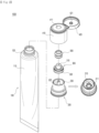
- FIG. 2 is an exploded perspective view showing the container according to the embodiment of the present invention
- FIG. 3 is a sectional view showing the container according to the embodiment of the present invention
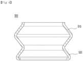
- FIG. 4 is a sectional view showing an elastic member of the container according to the embodiment of the present invention.
- a container 1000 includes a container part 100, a connection part 200, a discharging part 300, a cap part 400, and an elastic member 500.
- the container part 100 stores a given content therein.
- the given content is a solid, semi-solid, powder, liquid or gel cosmetic content.
- the content may be lotion, milk lotion, moisture lotion, nutrition lotion, skin lotion, skin softer, skin toner, astringent, massage cream, nutrition cream, whitening essence, tone-up cream, sunblock, sun cream, sun milk, BB cream, base, foundation, CC cream, concealer, blusher, shade, eyeshadow, eyebrow, eye cream, primer, and the like.
- the content may not be limited thereto, and therefore, the content may include different formulations or types of cosmetics or medicines.
- the container part 100 includes a storage part 110 and a shoulder part 120.
- the storage part 110 has a storage space portion for storing a content therein. Further, the storage part 110 is made of a soft material so that when it is pressurized, a volume of the storage space portion decreases. As the volume of storage space portion decreases, the content is discharged to the outside of the storage part 110.
- the storage part 110 has the shape of a tube, but without being limited thereto, the storage part 110 may have the shapes of all soft containers capable of being decreased in volume when pressurized.
- the shoulder part 120 is made of a hard material and coupled to a top of the storage part 110 in such a way as to support the storage part 110.
- a given region of the storage part 110 coupled to the shoulder part 120 does not decrease in volume when the storage part 110 is pressurized, so that the content stored in the storage part 111 moves to the shoulder part 120.
- the connection part 200 is disposed inside the shoulder part 120, and the content moving to the shoulder part 120 by means of the pressurization against the storage part 110 is introduced into the connection part 200.
- connection part 200 is provided on top of the container part 100 in such a way as to introduce the content discharged from the container part 100 thereinto.
- the connection part 200 has at least one or more inlets 211 adapted to introduce the content.
- the content is introduced into the connection part 200 through the inlets 211 when the container part 100 is pressurized.
- connection part 200 includes a seating portion 210, an opening and closing rod 220, and a peripheral wall 240.
- the seating portion 210 is seated on top of the container part 100 and has the inlets 211 formed thereon.
- the seating portion 210 is seated on top of the shoulder part 120, and the inlets 211 are formed on top of the seating portion 210.
- the inlets 211 are located inside the shoulder part 120 in such a way as to allow the content discharged from the container part 100 to be introduced thereinto.
- the opening and closing rod 220 extends upward from the insides of the inlets 211. As a result, the opening and closing rod 220 comes into close contact with the inside of the discharging part 300 (especially the inside of an outlet 310), so that in a state where the container part 100 is not pressurized, the opening and closing rod 220 seals the container 1000.
- the peripheral wall 230 extends upward from a given region of the seating portion 210 outside the inlets 211.
- the peripheral wall 230 comes into close contact with at least a portion of the discharging part 300 (especially a ring portion 320), so that the content introduced into the connection part 200 is prevented from leaking.
- the discharging part 300 serves to discharge the content introduced into the connection part 200 to the outside.
- the discharging part 300 is ascended and descended along the connection part 200.
- the discharging part 300 is ascended and descended, it is determined whether the content is discharged or not.
- the discharging part 300 is located inside the peripheral wall 230 in such a way as to surround the opening and closing rod 220.
- the discharging part 300 has the outlet 310.
- the outlet 310 is formed on top of the discharging part 300 in such a way as to be open and closed as the discharging part 300 is ascended and descended.
- the outlet 310 comes into close contact with the opening and closing rod 220 and is thus closed, and contrarily, if the discharging part 300 moves up and is thus in a second position, the close contact of the outlet 310 with the opening and closing rod 220 is released so that the outlet 310 is open.
- the discharging part 300 includes the ring portion 320.
- the ring portion 320 is ascended and descended, while coming into close contact with the peripheral wall 230. That is, the ring portion 320 allows the discharging part 300 to be ascended and descended, while permitting the content introduced into the connection part 200 to be discharged only through the outlet 310 to the outside, so that the content is prevented from leaking inside the container 1000.
- the cap part 400 is located on top of the discharging part 300 and surrounds at least portions of the connection part 200, the discharging part 300, and the elastic member 500.
- the cap part 400 has an insertion hole 411 adapted to insert the discharging part 300 thereinto, and the discharging part 300 is exposed to the outside from the insertion hole 411.
- top of the discharging part 300 is aligned with top of the insertion hole 411 or located inside the insertion hole 411, and if the container part 400 is pressurized, the discharging part 300 moves up and is thus exposed to the outside from the insertion hole 411. In the state where the container part 400 is not pressurized, top of the discharging part 300 is not exposed to the outside, and therefore, the discharging part 300 is prevented from being contaminated.
- the cap part 400 includes a first cap part 410 adapted to surround the connection part 200 and having the insertion hole 411 formed on top thereof; and a second cap part 420 rotatably coupled to the first cap part 410 in such a way as to open and close the insertion hole 411.
- at least one hinge part is located between the first cap part 410 and the second cap part 420 to allow the first cap part 410 and the second cap part 420 to be rotatably coupled to each other, but without being limited thereto, various rotatable coupling structures may be applied to allow the first cap part 410 and the second cap part 420 to be rotatably coupled to each other.
- the second cap part 420 has a pressurizing portion 421 protruding from an underside thereof.
- the pressurizing portion 421 serves to pressurize top of the discharging part 300, if the second cap part 420 closes the insertion hole 411, to prevent the discharging part 300 from unintentionally moving up, so that the content is prevented from being unintentionally discharged to the outside.
- the elastic member 500 is disposed between the discharging part 300 and the cap part 400 to apply an elastic force to the discharging part 300. If the container part 100 is pressurized to allow the content to be introduced into the connection part 200, the elastic member 500 is compressed so that the discharging part 300 moves up to open the outlet 310, and contrarily, if the pressurization against the container part 100 is released, the elastic member 500 pressurizes the discharging part 300 downward so that the discharging part 300 moves down to close the outlet 310.
- the elastic member 500 is a bellows type member having a peak and troughs formed in a longitudinal direction thereof, while being sealed on the peripheral surface thereof.
- the elastic force of the elastic member 500 increases, and the elastic member 500 is naturally compressed and released from the compressed state.
- the bellows type elastic member 500 is made of a plastic material, not a metal material, it exerts an appropriate elastic force.
- the elastic member 500 includes a body 510 having the peak and troughs and generating the elastic force when compressed; and a supporter 520 located on the underside of the body 510 to transfer the elastic force to the discharging part 300.
- the body 510 is bent to first curvature between the peak and the trough, and the supporter 520 extends downward and outward from the trough on the bottom of the body 510 and is then bent inward from the underside thereof to second curvature different from the first curvature.
- the second curvature is larger than the first curvature.
- the body 510 is bent to the first curvature, it is compressed to a first compression rate when compressed, and as the supporter 520 is bent to the second curvature, it is compressed to a second compression rate lower than the first compression rate when compressed.
- the body 510 is compressed to the first compression rate to generate the elastic force, and the supporter 520 is compressed to the second compression rate and stably transfers the elastic force downward.
- the inner upper peripheral surface of the body 510 comes into close contact with the cap part 400 and is supported against the cap part 400
- the outer lower peripheral surface of the supporter 520 comes into close contact with the discharging part 300 and is supported against the discharging part 300.
- the container 1000 as shown in FIGs. 1 to 4 is just exemplary, and therefore, the container 1000 may have various configurations according to embodiments of the present invention.
- FIG. 5 is a sectional view showing operations of the container according to the embodiment of the present invention.
- FIG. 5a is a sectional view showing a state of the container 1000 where the container part 100 is not pressurized
- FIG. 5b is a sectional view showing a state of the container 1000 where the container part 100 is pressurized.
- the opening and closing rod 220 comes into close contact with the inside of the outlet 310 so that the outlet 310 is closed.
- the container part 100 If the container part 100 is pressurized, the content stored in the storage part 110 moves to the shoulder part 120 and is introduced into the connection part 200 through the inlets 211. If the content moves to the connection part 200, the elastic member 500 is compressed to move up the discharging part 300. As the discharging part 300 moves up, the close contact between the outlet 310 and the opening and closing rod 220 is released to open the outlet 310. If the outlet 310 is open, the content moving to the connection part 200 is discharged to the outside through the outlet 310.
- the compressed elastic member 500 pressurizes the discharging part 300 downward to move down the discharging part 300.
- the outlet 310 comes into close contact with the opening and closing rod 220 again and is thus closed.
- the operations of the container 1000 as shown in FIG. 5 are just exemplary, and therefore, the operations of the container 1000 may be freely performed according to embodiments of the present invention.
Landscapes
- Engineering & Computer Science (AREA)
- Mechanical Engineering (AREA)
- Containers And Packaging Bodies Having A Special Means To Remove Contents (AREA)
- Closures For Containers (AREA)
Abstract
Description
- The present invention relates to a container.
- As modern societies have been developed, various cosmetics, medicines, quasi-drugs, etc. are developed and introduced, and accordingly, different types of containers for storing a variety of types and formulations of contents therein are suggested. For example, a content such as cream or gel is stored in a container such as a tube, and if a soft storage portion of the tube is pressurized, a volume of the storage portion decreases, so that the content stored in the tube is discharged to the outside.
- If a cap of the tube is open to use the content, however, the content of the tube is exposed immediately to the outside through an open portion of the tube, and when exposed, external air or dust is introduced into the tube through the open portion, so that the content may be contaminated. Therefore, there is a need to develop a container capable of being reliably sealed to prevent the content stored therein from being contaminated with external air or dust.
- It is an object of the present invention to provide a container that is capable of solving the above-mentioned problems occurring in the related art.
- The technical problems to be achieved through the present invention are not limited as mentioned above, and other technical problems not mentioned herein will be obviously understood by one of ordinary skill in the art through the following description.
- To accomplish the above-mentioned objects, according to the present invention, there is provided a container. The container may include: a container part for storing a content therein; a connection part provided on top of the container part and having at least one or more inlets adapted to introduce the content thereinto; a discharging part ascended and descended along the connection part and having an outlet for discharging the content, the outlet being open and closed according to ascending and descending; a cap part located on top of the discharging part and having an insertion hole adapted to insert the discharging part thereinto; and an elastic member disposed between the discharging part and the cap part to apply an elastic force to the discharging part, wherein the elastic member is a bellows type member having a peak and troughs formed in a longitudinal direction thereof, while being sealed on the peripheral surface thereof.
- According to the present invention, the container is configured to allow the outlet to be closed in a state where the container part is not pressurized, thereby preventing the content from being contaminated, and to allow the outlet to be open if the container part is pressurized, thereby enabling the use of the content with ease.
- According to the present invention, further, the container is configured to allow the bellows type elastic member having the peak and troughs formed in a longitudinal direction thereof, while being sealed on the peripheral surface thereof, to open and close the outlet, so that the elastic force of the elastic member increases, the elastic member is more naturally compressed and released from the compressed state, and the elastic force is more easily transferred.
- To allow the drawings as will be mentioned in the description of the present invention to be more sufficiently understood, the brief description of the drawings may be provided.
-
FIG. 1 is a perspective view showing a container according to an embodiment of the present invention. -
FIG. 2 is an exploded perspective view showing the container according to the embodiment of the present invention. -
FIG. 3 is a sectional view showing the container according to the embodiment of the present invention. -
FIG. 4 is a sectional view showing an elastic member of the container according to the embodiment of the present invention. -
FIG. 5 is a sectional view showing operations of the container according to the embodiment of the present invention. - According to an embodiment of the present invention is provided a container. The container includes: a container part for storing a content therein; a connection part provided on top of the container part and having at least one or more inlets adapted to introduce the content thereinto; a discharging part ascended and descended along the connection part and having an outlet for discharging the content, the outlet being open and closed according to ascending and descending; a cap part located on top of the discharging part and having an insertion hole adapted to insert the discharging part thereinto; and an elastic member disposed between the discharging part and the cap part to apply an elastic force to the discharging part, wherein the elastic member is a bellows type member having a peak and troughs formed in a longitudinal direction thereof, while being sealed on the peripheral surface thereof.
- Further, if the container part is pressurized, the content is introduced into the connection part through the inlets to allow the elastic member to be compressed so that the discharging part moves up to open the outlet, and if the pressurization against the container part is released, the elastic member pressurizes the discharging part downward so that the discharging part moves down to close the outlet.
- Furthermore, the elastic member includes: a body having the peak and troughs and generating the elastic force when compressed; and a supporter located on the underside of the body to transfer the elastic force to the discharging part.
- Besides, the body is bent to first curvature between the peak and the adjacent trough, and the supporter extends downward and outward from the trough on the bottom of the body and is then bent inward from the underside thereof to second curvature different from the first curvature.
- Moreover, an inner upper peripheral surface of the body comes into close contact with the cap part and is supported against the cap part, and an outer lower peripheral surface of the supporter comes into close contact with the discharging part and is supported against the discharging part.
- Further, the container part includes: a soft storage part for storing the content therein; and a hard shoulder part coupled to a top of the storage part.
- Additionally, the connection part includes: a seating portion seated on top of the container part and having the inlets formed thereon; and an opening and closing rod extending upward from a given region of the seating portion inside the inlets and coming into close contact with the inside of the outlet.
- Furthermore, if the container part is pressurized, the discharging part moves up to allow the close contact between the opening and closing rod and the outlet to be released so that through the outlet, the content is discharged.
- Moreover, the connection part has a peripheral wall extending upward from a given region of the seating portion outside the inlets, and the discharging part has a ring portion ascended and descended, while coming into close contact with the peripheral wall, to prevent the content from leaking.
- Further, the cap part includes: a first cap part adapted to surround the connection part and having the insertion hole formed on top thereof; and a second cap part rotatably coupled to the first cap part in such a way as to open and close the insertion hole.
- Furthermore, top of the discharging part is aligned with top of the insertion hole or located inside the insertion hole, and if the container part is pressurized, the discharging part moves up and is thus exposed to the outside from the insertion hole.
- Hereinafter, exemplary embodiments of the present invention will be described in detail with reference to the accompanying drawings. Further, a method for configuring and using a device according to the embodiment of the present invention will be explained in detail with reference to the attached drawings and specification. In the drawings, reference numerals or symbols, with respect to the same elements, even though they may be displayed in different drawings, such elements use same reference numerals as much as possible. Further, top, bottom, left and right directions as will be described below are determined with reference to the drawings, and accordingly, the scope of the present invention is not necessarily restricted to the corresponding directions.
- It shall be understood that, although the terms "first," "second," etc. may be used herein to describe various information, the information should not be limited by these terms. These terms are only used to distinguish one category of information from another. For example, a first element may be named a second element without departing from the scope of the present invention. Likewise, a second element may be named a first element.
- Terms used in this application are used to only describe specific exemplary embodiments and are not intended to restrict the present invention. An expression referencing a singular value additionally refers to a corresponding expression of the plural number, unless explicitly limited otherwise by the context. In this application, terms, such as "comprise", "include", or "have", are intended to designate those characteristics, numbers, steps, operations, elements, or parts which are described in the specification, or any combination of them that exist, and it should be understood that they do not preclude the possibility of the existence or possible addition of one or more additional characteristics, numbers, steps, operations, elements, or parts, or combinations thereof.
- In the entire specification, when it is said that one element is described as being "connected" or "coupled" to the other element, one element may be directly connected or coupled to the other element, but it should be understood that another element may be present between the two elements. Further, when it is said that one portion is described as "includes" any component, one element further may include other components unless no specific description is suggested.
-
FIG. 1 is a perspective view showing a container according to an embodiment of the present invention,FIG. 2 is an exploded perspective view showing the container according to the embodiment of the present invention,FIG. 3 is a sectional view showing the container according to the embodiment of the present invention, andFIG. 4 is a sectional view showing an elastic member of the container according to the embodiment of the present invention. - Referring to
FIGs. 1 to 4 , acontainer 1000 according to an embodiment of the present invention includes acontainer part 100, aconnection part 200, adischarging part 300, acap part 400, and anelastic member 500. - The
container part 100 stores a given content therein. In this case, the given content is a solid, semi-solid, powder, liquid or gel cosmetic content. For example, the content may be lotion, milk lotion, moisture lotion, nutrition lotion, skin lotion, skin softer, skin toner, astringent, massage cream, nutrition cream, whitening essence, tone-up cream, sunblock, sun cream, sun milk, BB cream, base, foundation, CC cream, concealer, blusher, shade, eyeshadow, eyebrow, eye cream, primer, and the like. However, the content may not be limited thereto, and therefore, the content may include different formulations or types of cosmetics or medicines. - According to the embodiment of the present invention, the
container part 100 includes astorage part 110 and ashoulder part 120. - The
storage part 110 has a storage space portion for storing a content therein. Further, thestorage part 110 is made of a soft material so that when it is pressurized, a volume of the storage space portion decreases. As the volume of storage space portion decreases, the content is discharged to the outside of thestorage part 110. For example, thestorage part 110 has the shape of a tube, but without being limited thereto, thestorage part 110 may have the shapes of all soft containers capable of being decreased in volume when pressurized. - The
shoulder part 120 is made of a hard material and coupled to a top of thestorage part 110 in such a way as to support thestorage part 110. As theshoulder part 120 is made of a hard material, a given region of thestorage part 110 coupled to theshoulder part 120 does not decrease in volume when thestorage part 110 is pressurized, so that the content stored in the storage part 111 moves to theshoulder part 120. Further, theconnection part 200 is disposed inside theshoulder part 120, and the content moving to theshoulder part 120 by means of the pressurization against thestorage part 110 is introduced into theconnection part 200. - The
connection part 200 is provided on top of thecontainer part 100 in such a way as to introduce the content discharged from thecontainer part 100 thereinto. To do this, theconnection part 200 has at least one ormore inlets 211 adapted to introduce the content. In detail, the content is introduced into theconnection part 200 through theinlets 211 when thecontainer part 100 is pressurized. - According to the embodiment of the present invention, the
connection part 200 includes aseating portion 210, an opening and closingrod 220, and a peripheral wall 240. - The
seating portion 210 is seated on top of thecontainer part 100 and has theinlets 211 formed thereon. In detail, theseating portion 210 is seated on top of theshoulder part 120, and theinlets 211 are formed on top of theseating portion 210. In this case, theinlets 211 are located inside theshoulder part 120 in such a way as to allow the content discharged from thecontainer part 100 to be introduced thereinto. - The opening and closing
rod 220 extends upward from the insides of theinlets 211. As a result, the opening and closingrod 220 comes into close contact with the inside of the discharging part 300 (especially the inside of an outlet 310), so that in a state where thecontainer part 100 is not pressurized, the opening and closingrod 220 seals thecontainer 1000. - The
peripheral wall 230 extends upward from a given region of theseating portion 210 outside theinlets 211. Theperipheral wall 230 comes into close contact with at least a portion of the discharging part 300 (especially a ring portion 320), so that the content introduced into theconnection part 200 is prevented from leaking. - The discharging
part 300 serves to discharge the content introduced into theconnection part 200 to the outside. In this case, the dischargingpart 300 is ascended and descended along theconnection part 200. As the dischargingpart 300 is ascended and descended, it is determined whether the content is discharged or not. For example, the dischargingpart 300 is located inside theperipheral wall 230 in such a way as to surround the opening and closingrod 220. - According to the embodiment of the present invention, the discharging
part 300 has theoutlet 310. Theoutlet 310 is formed on top of the dischargingpart 300 in such a way as to be open and closed as the dischargingpart 300 is ascended and descended. In detail, if the dischargingpart 300 moves down and is thus in a first position, theoutlet 310 comes into close contact with the opening and closingrod 220 and is thus closed, and contrarily, if the dischargingpart 300 moves up and is thus in a second position, the close contact of theoutlet 310 with the opening and closingrod 220 is released so that theoutlet 310 is open. - According to the embodiment of the present invention, the discharging
part 300 includes thering portion 320. Thering portion 320 is ascended and descended, while coming into close contact with theperipheral wall 230. That is, thering portion 320 allows the dischargingpart 300 to be ascended and descended, while permitting the content introduced into theconnection part 200 to be discharged only through theoutlet 310 to the outside, so that the content is prevented from leaking inside thecontainer 1000. - The
cap part 400 is located on top of the dischargingpart 300 and surrounds at least portions of theconnection part 200, the dischargingpart 300, and theelastic member 500. In this case, thecap part 400 has aninsertion hole 411 adapted to insert the dischargingpart 300 thereinto, and the dischargingpart 300 is exposed to the outside from theinsertion hole 411. - According to the embodiment of the present invention, top of the discharging
part 300 is aligned with top of theinsertion hole 411 or located inside theinsertion hole 411, and if thecontainer part 400 is pressurized, the dischargingpart 300 moves up and is thus exposed to the outside from theinsertion hole 411. In the state where thecontainer part 400 is not pressurized, top of the dischargingpart 300 is not exposed to the outside, and therefore, the dischargingpart 300 is prevented from being contaminated. - According to the embodiment of the present invention, the
cap part 400 includes afirst cap part 410 adapted to surround theconnection part 200 and having theinsertion hole 411 formed on top thereof; and asecond cap part 420 rotatably coupled to thefirst cap part 410 in such a way as to open and close theinsertion hole 411. In this case, for example, at least one hinge part is located between thefirst cap part 410 and thesecond cap part 420 to allow thefirst cap part 410 and thesecond cap part 420 to be rotatably coupled to each other, but without being limited thereto, various rotatable coupling structures may be applied to allow thefirst cap part 410 and thesecond cap part 420 to be rotatably coupled to each other. - According to the embodiment of the present invention, the
second cap part 420 has a pressurizingportion 421 protruding from an underside thereof. The pressurizingportion 421 serves to pressurize top of the dischargingpart 300, if thesecond cap part 420 closes theinsertion hole 411, to prevent the dischargingpart 300 from unintentionally moving up, so that the content is prevented from being unintentionally discharged to the outside. - The
elastic member 500 is disposed between the dischargingpart 300 and thecap part 400 to apply an elastic force to the dischargingpart 300. If thecontainer part 100 is pressurized to allow the content to be introduced into theconnection part 200, theelastic member 500 is compressed so that the dischargingpart 300 moves up to open theoutlet 310, and contrarily, if the pressurization against thecontainer part 100 is released, theelastic member 500 pressurizes the dischargingpart 300 downward so that the dischargingpart 300 moves down to close theoutlet 310. - According to the embodiment of the present invention, the
elastic member 500 is a bellows type member having a peak and troughs formed in a longitudinal direction thereof, while being sealed on the peripheral surface thereof. In this case, the elastic force of theelastic member 500 increases, and theelastic member 500 is naturally compressed and released from the compressed state. Further, even if the bellows typeelastic member 500 is made of a plastic material, not a metal material, it exerts an appropriate elastic force. - According to the embodiment of the present invention, the
elastic member 500 includes abody 510 having the peak and troughs and generating the elastic force when compressed; and asupporter 520 located on the underside of thebody 510 to transfer the elastic force to the dischargingpart 300. - According to the embodiment of the present invention, the
body 510 is bent to first curvature between the peak and the trough, and thesupporter 520 extends downward and outward from the trough on the bottom of thebody 510 and is then bent inward from the underside thereof to second curvature different from the first curvature. In this case, for example, the second curvature is larger than the first curvature. As a result, a degree of an external force required for the compression of thesupporter 520 bent to the second curvature is bigger than a degree of an external force required for the compression of thebody 510 bent to the first curvature. That is, as thebody 510 is bent to the first curvature, it is compressed to a first compression rate when compressed, and as thesupporter 520 is bent to the second curvature, it is compressed to a second compression rate lower than the first compression rate when compressed. Thebody 510 is compressed to the first compression rate to generate the elastic force, and thesupporter 520 is compressed to the second compression rate and stably transfers the elastic force downward. - According to the embodiment of the present invention, the inner upper peripheral surface of the
body 510 comes into close contact with thecap part 400 and is supported against thecap part 400, and the outer lower peripheral surface of thesupporter 520 comes into close contact with the dischargingpart 300 and is supported against the dischargingpart 300. As a result, theelastic member 500 is prevented from escaping when compressed and released from the compressed state, and further, the transfer direction of the elastic force is induced in a vertical direction. - The
container 1000 as shown inFIGs. 1 to 4 is just exemplary, and therefore, thecontainer 1000 may have various configurations according to embodiments of the present invention. -
FIG. 5 is a sectional view showing operations of the container according to the embodiment of the present invention. In detail,FIG. 5a is a sectional view showing a state of thecontainer 1000 where thecontainer part 100 is not pressurized, andFIG. 5b is a sectional view showing a state of thecontainer 1000 where thecontainer part 100 is pressurized. - Referring to
FIG. 5 , in the state where thecontainer part 100 is not pressurized, the opening and closingrod 220 comes into close contact with the inside of theoutlet 310 so that theoutlet 310 is closed. - If the
container part 100 is pressurized, the content stored in thestorage part 110 moves to theshoulder part 120 and is introduced into theconnection part 200 through theinlets 211. If the content moves to theconnection part 200, theelastic member 500 is compressed to move up the dischargingpart 300. As the dischargingpart 300 moves up, the close contact between theoutlet 310 and the opening and closingrod 220 is released to open theoutlet 310. If theoutlet 310 is open, the content moving to theconnection part 200 is discharged to the outside through theoutlet 310. - After that, if the pressurization against the
container part 100 is released, the compressedelastic member 500 pressurizes the dischargingpart 300 downward to move down the dischargingpart 300. As the dischargingpart 300 moves down, theoutlet 310 comes into close contact with the opening and closingrod 220 again and is thus closed. - The operations of the
container 1000 as shown inFIG. 5 are just exemplary, and therefore, the operations of thecontainer 1000 may be freely performed according to embodiments of the present invention. - While the present invention has been described with reference to the particular illustrative embodiments, it is not to be restricted by the embodiments but only by the appended claims. It is to be appreciated that those skilled in the art can change or modify the embodiments without departing from the scope and spirit of the present invention. It should be therefore understood that the embodiments of the present invention are just exemplary embodiments, while not limiting the present invention. Persons skilled in the relevant art can appreciate that many modifications and variations are possible in light of the above teachings. It is therefore intended that the scope of the invention be limited not by this detailed description, but rather by the claims appended hereto.
Claims (11)
- A container comprising:a container part for storing a content therein;a connection part provided on top of the container part and having at least one or more inlets adapted to introduce the content thereinto;a discharging part ascended and descended along the connection part and having an outlet for discharging the content, the outlet being open and closed according to ascending and descending;a cap part located on top of the discharging part and having an insertion hole adapted to insert the discharging part thereinto; andan elastic member disposed between the discharging part and the cap part to apply an elastic force to the discharging part,wherein the elastic member is a bellows type member having a peak and troughs formed in a longitudinal direction thereof, while being sealed on the peripheral surface thereof.
- The container according to claim 1, wherein if the container part is pressurized, the content is introduced into the connection part through the inlets to allow the elastic member to be compressed so that the discharging part moves up to open the outlet, and if the pressurization against the container part is released, the elastic member pressurizes the discharging part downward so that the discharging part moves down to close the outlet.
- The container according to claim 1, wherein the elastic member comprises: a body having the peak and troughs and generating the elastic force when compressed; and a supporter located on the underside of the body to transfer the elastic force to the discharging part.
- The container according to claim 3, wherein the body is bent to first curvature between the peak and the adjacent trough, and the supporter extends downward and outward from the trough on the bottom of the body and is then bent inward from the underside thereof to second curvature different from the first curvature.
- The container according to claim 3, wherein an inner upper peripheral surface of the body comes into close contact with the cap part and is supported against the cap part, and an outer lower peripheral surface of the supporter comes into close contact with the discharging part and is supported against the discharging part.
- The container according to claim 1, wherein the container part comprises: a soft storage part for storing the content therein; and a hard shoulder part coupled to a top of the storage part.
- The container according to claim 1, wherein the connection part comprises: a seating portion seated on top of the container part and having the inlets formed thereon; and an opening and closing rod extending upward from a given region of the seating portion inside the inlets and coming into close contact with the inside of the outlet.
- The container according to claim 7, wherein if the container part is pressurized, the discharging part moves up to allow the close contact between the opening and closing rod and the outlet to be released so that through the outlet, the content is discharged.
- The container according to claim 7, wherein the connection part has a peripheral wall extending upward from a given region of the seating portion outside the inlets, and the discharging part has a ring portion ascended and descended, while coming into close contact with the peripheral wall, to prevent the content from leaking.
- The container according to claim 1, wherein the cap part comprises: a first cap part adapted to surround the connection part and having the insertion hole formed on top thereof; and a second cap part rotatably coupled to the first cap part in such a way as to open and close the insertion hole.
- The container according to claim 10, wherein top of the discharging part is aligned with top of the insertion hole or located inside the insertion hole, and if the container part is pressurized, the discharging part moves up and is thus exposed to the outside from the insertion hole.
Applications Claiming Priority (2)
| Application Number | Priority Date | Filing Date | Title |
|---|---|---|---|
| KR1020220029386A KR102730461B1 (en) | 2022-03-08 | 2022-03-08 | Container |
| PCT/KR2023/003071 WO2023172015A1 (en) | 2022-03-08 | 2023-03-07 | Content container |
Publications (2)
| Publication Number | Publication Date |
|---|---|
| EP4450420A1 true EP4450420A1 (en) | 2024-10-23 |
| EP4450420A4 EP4450420A4 (en) | 2025-04-16 |
Family
ID=87935433
Family Applications (1)
| Application Number | Title | Priority Date | Filing Date |
|---|---|---|---|
| EP23767116.9A Pending EP4450420A4 (en) | 2022-03-08 | 2023-03-07 | CONTENT CONTAINER |
Country Status (6)
| Country | Link |
|---|---|
| US (1) | US20250108959A1 (en) |
| EP (1) | EP4450420A4 (en) |
| JP (1) | JP7781296B2 (en) |
| KR (1) | KR102730461B1 (en) |
| CN (1) | CN118679105A (en) |
| WO (1) | WO2023172015A1 (en) |
Family Cites Families (19)
| Publication number | Priority date | Publication date | Assignee | Title |
|---|---|---|---|---|
| FR787371A (en) * | 1935-03-14 | 1935-09-21 | Device for sampling products delivered in malleable tubes | |
| DE8207739U1 (en) * | 1982-03-19 | 1982-08-19 | Held, Wolfgang, 7915 Elchingen | Cap that can be placed on a container for liquids that has a central outlet opening |
| DE9311617U1 (en) * | 1993-08-05 | 1994-09-15 | Wolff, Ernst, 33330 Gütersloh | Closure for containers with liquid or pasty contents |
| US5518147A (en) * | 1994-03-01 | 1996-05-21 | The Procter & Gamble Company | Collapsible pump chamber having predetermined collapsing pattern |
| JPH10258865A (en) * | 1997-03-17 | 1998-09-29 | Lion Corp | Trigger spray container |
| JP2003081296A (en) * | 2001-09-10 | 2003-03-19 | Katsutoshi Masuda | Tube type container |
| FR2833579B1 (en) * | 2001-12-13 | 2004-10-08 | Plastohm Sa | STERILE DISPENSING SYSTEM FOR A PRODUCT CONTAINED IN A CONTAINER, IN PARTICULAR A FLEXIBLE TUBE |
| JP2004067099A (en) * | 2002-06-10 | 2004-03-04 | Katsutoshi Masuda | Valve mechanism |
| FR2929249B1 (en) * | 2008-03-27 | 2012-02-17 | Rexam Pharma La Verpilliere | DEVICE FOR DISPENSING LIQUID CONTAINED IN A RESERVOIR |
| FR2937019B1 (en) * | 2008-10-15 | 2012-06-08 | Rexam Pharma La Verpilliere | LIQUID DISPENSING DEVICE WITH SEALING BODY HAVING AN ELASTOMERIC PART |
| FR2950036B1 (en) * | 2009-09-11 | 2011-12-16 | Rexam Pharma La Verpilliere | DEVICE FOR DISTRIBUTING LIQUID |
| AT509749B1 (en) * | 2010-04-23 | 2012-11-15 | Hagleitner Hans Georg | DONOR |
| FR2963326B1 (en) * | 2010-07-30 | 2012-09-07 | Rexam Healthcare La Verpillier | TIP AND CONTAINER FOR DISTRIBUTING LIQUID |
| FR2967141B1 (en) * | 2010-11-04 | 2014-02-21 | Valois Sas | FLUID PRODUCT DISPENSING HEAD AND DISPENSER COMPRISING SUCH A DISPENSING HEAD. |
| KR101335570B1 (en) * | 2012-03-12 | 2013-12-02 | (주)연우 | Tube type cosmetic case |
| JP2015048104A (en) | 2013-08-30 | 2015-03-16 | 武内プレス工業株式会社 | Droplet vessel |
| FR3013337B1 (en) * | 2013-11-20 | 2016-07-08 | Promens Sa | SYSTEM FOR STERILE DISTRIBUTION OF A PRODUCT CONTAINED IN A FLEXIBLE TUBE COMPRISING COMPLEMENTARY SEALING MEANS |
| JP6575122B2 (en) * | 2015-04-20 | 2019-09-18 | 凸版印刷株式会社 | Cap with backflow prevention valve and container with the cap attached |
| KR102171859B1 (en) * | 2019-01-07 | 2020-10-29 | (주)연우 | A button retractable type container for cometics |
-
2022
- 2022-03-08 KR KR1020220029386A patent/KR102730461B1/en active Active
-
2023
- 2023-03-07 WO PCT/KR2023/003071 patent/WO2023172015A1/en not_active Ceased
- 2023-03-07 EP EP23767116.9A patent/EP4450420A4/en active Pending
- 2023-03-07 US US18/833,273 patent/US20250108959A1/en active Pending
- 2023-03-07 JP JP2024546346A patent/JP7781296B2/en active Active
- 2023-03-07 CN CN202380020977.7A patent/CN118679105A/en active Pending
Also Published As
| Publication number | Publication date |
|---|---|
| WO2023172015A1 (en) | 2023-09-14 |
| US20250108959A1 (en) | 2025-04-03 |
| EP4450420A4 (en) | 2025-04-16 |
| KR102730461B1 (en) | 2024-11-15 |
| CN118679105A (en) | 2024-09-20 |
| JP2025505017A (en) | 2025-02-19 |
| JP7781296B2 (en) | 2025-12-05 |
| KR20230132181A (en) | 2023-09-15 |
Similar Documents
| Publication | Publication Date | Title |
|---|---|---|
| US5897263A (en) | Cosmetic dispensing package | |
| US9788633B2 (en) | Extrusion type cosmetic container | |
| US20190269221A1 (en) | Rotating open-and-closed type cosmetic container | |
| US20180178232A1 (en) | Container for discharging powder | |
| US20250242980A1 (en) | Content container | |
| CN215271051U (en) | Contents container | |
| US6536447B1 (en) | Cosmetic compact | |
| KR102089722B1 (en) | Slim Cosmetic Container Maintaining Weight Balance When Opening the Container Cover | |
| KR20150118881A (en) | Press-type dispensing container | |
| US20250108959A1 (en) | Substance container | |
| KR102161468B1 (en) | Cosmetic container with a massage function | |
| US5895162A (en) | Application unit for a lipstick-type product | |
| KR102134295B1 (en) | Cosmetic container | |
| JP7698798B2 (en) | contents container | |
| US12378039B2 (en) | Container | |
| KR20200050543A (en) | Cosmetic container | |
| EP4449943A1 (en) | Substance container | |
| KR102643868B1 (en) | Container | |
| KR102478611B1 (en) | Container | |
| KR102957761B1 (en) | Container | |
| KR20200137629A (en) | Lipstick case | |
| EP4556394A1 (en) | Contents container | |
| AU2023289227B2 (en) | Content container | |
| US20260070707A1 (en) | Content container | |
| KR20230157665A (en) | Container |
Legal Events
| Date | Code | Title | Description |
|---|---|---|---|
| STAA | Information on the status of an ep patent application or granted ep patent |
Free format text: STATUS: THE INTERNATIONAL PUBLICATION HAS BEEN MADE |
|
| PUAI | Public reference made under article 153(3) epc to a published international application that has entered the european phase |
Free format text: ORIGINAL CODE: 0009012 |
|
| STAA | Information on the status of an ep patent application or granted ep patent |
Free format text: STATUS: REQUEST FOR EXAMINATION WAS MADE |
|
| 17P | Request for examination filed |
Effective date: 20240716 |
|
| AK | Designated contracting states |
Kind code of ref document: A1 Designated state(s): AL AT BE BG CH CY CZ DE DK EE ES FI FR GB GR HR HU IE IS IT LI LT LU LV MC ME MK MT NL NO PL PT RO RS SE SI SK SM TR |
|
| A4 | Supplementary search report drawn up and despatched |
Effective date: 20250318 |
|
| RIC1 | Information provided on ipc code assigned before grant |
Ipc: A45D 40/00 20060101ALI20250312BHEP Ipc: A45D 34/00 20060101ALI20250312BHEP Ipc: B65D 47/20 20060101ALI20250312BHEP Ipc: B65D 35/46 20060101AFI20250312BHEP |
|
| DAV | Request for validation of the european patent (deleted) | ||
| DAX | Request for extension of the european patent (deleted) |