EP4450407A1 - Packer machine and wrapping method to obtain a pack of cigarettes provided with an outer container and a hinged lid by folding a blank around a wrap enclosing a group of smoking articles - Google Patents
Packer machine and wrapping method to obtain a pack of cigarettes provided with an outer container and a hinged lid by folding a blank around a wrap enclosing a group of smoking articles Download PDFInfo
- Publication number
- EP4450407A1 EP4450407A1 EP24169880.2A EP24169880A EP4450407A1 EP 4450407 A1 EP4450407 A1 EP 4450407A1 EP 24169880 A EP24169880 A EP 24169880A EP 4450407 A1 EP4450407 A1 EP 4450407A1
- Authority
- EP
- European Patent Office
- Prior art keywords
- transfer station
- wings
- wrap
- cigarettes
- blank
- Prior art date
- Legal status (The legal status is an assumption and is not a legal conclusion. Google has not performed a legal analysis and makes no representation as to the accuracy of the status listed.)
- Pending
Links
Images



Classifications
-
- B—PERFORMING OPERATIONS; TRANSPORTING
- B65—CONVEYING; PACKING; STORING; HANDLING THIN OR FILAMENTARY MATERIAL
- B65B—MACHINES, APPARATUS OR DEVICES FOR, OR METHODS OF, PACKAGING ARTICLES OR MATERIALS; UNPACKING
- B65B19/00—Packaging rod-shaped or tubular articles susceptible to damage by abrasion or pressure, e.g. cigarettes, cigars, macaroni, spaghetti, drinking straws or welding electrodes
- B65B19/02—Packaging cigarettes
- B65B19/22—Wrapping the cigarettes; Packaging the cigarettes in containers formed by folding wrapping material around formers
-
- B—PERFORMING OPERATIONS; TRANSPORTING
- B65—CONVEYING; PACKING; STORING; HANDLING THIN OR FILAMENTARY MATERIAL
- B65B—MACHINES, APPARATUS OR DEVICES FOR, OR METHODS OF, PACKAGING ARTICLES OR MATERIALS; UNPACKING
- B65B19/00—Packaging rod-shaped or tubular articles susceptible to damage by abrasion or pressure, e.g. cigarettes, cigars, macaroni, spaghetti, drinking straws or welding electrodes
- B65B19/02—Packaging cigarettes
- B65B19/22—Wrapping the cigarettes; Packaging the cigarettes in containers formed by folding wrapping material around formers
- B65B19/223—Wrapping the cigarettes; Packaging the cigarettes in containers formed by folding wrapping material around formers in a curved path; in a combination of straight and curved paths, e.g. on rotary tables or other endless conveyors
-
- B—PERFORMING OPERATIONS; TRANSPORTING
- B65—CONVEYING; PACKING; STORING; HANDLING THIN OR FILAMENTARY MATERIAL
- B65B—MACHINES, APPARATUS OR DEVICES FOR, OR METHODS OF, PACKAGING ARTICLES OR MATERIALS; UNPACKING
- B65B19/00—Packaging rod-shaped or tubular articles susceptible to damage by abrasion or pressure, e.g. cigarettes, cigars, macaroni, spaghetti, drinking straws or welding electrodes
- B65B19/02—Packaging cigarettes
- B65B19/22—Wrapping the cigarettes; Packaging the cigarettes in containers formed by folding wrapping material around formers
- B65B19/228—Preparing and feeding blanks
-
- B—PERFORMING OPERATIONS; TRANSPORTING
- B65—CONVEYING; PACKING; STORING; HANDLING THIN OR FILAMENTARY MATERIAL
- B65B—MACHINES, APPARATUS OR DEVICES FOR, OR METHODS OF, PACKAGING ARTICLES OR MATERIALS; UNPACKING
- B65B49/00—Devices for folding or bending wrappers around contents
- B65B49/08—Reciprocating or oscillating folders
-
- B—PERFORMING OPERATIONS; TRANSPORTING
- B65—CONVEYING; PACKING; STORING; HANDLING THIN OR FILAMENTARY MATERIAL
- B65B—MACHINES, APPARATUS OR DEVICES FOR, OR METHODS OF, PACKAGING ARTICLES OR MATERIALS; UNPACKING
- B65B51/00—Devices for, or methods of, sealing or securing package folds or closures; Devices for gathering or twisting wrappers, or necks of bags
- B65B51/02—Applying adhesives or sealing liquids
- B65B51/023—Applying adhesives or sealing liquids using applicator nozzles
-
- B—PERFORMING OPERATIONS; TRANSPORTING
- B65—CONVEYING; PACKING; STORING; HANDLING THIN OR FILAMENTARY MATERIAL
- B65B—MACHINES, APPARATUS OR DEVICES FOR, OR METHODS OF, PACKAGING ARTICLES OR MATERIALS; UNPACKING
- B65B61/00—Auxiliary devices, not otherwise provided for, for operating on sheets, blanks, webs, binding material, containers or packages
- B65B61/002—Auxiliary devices, not otherwise provided for, for operating on sheets, blanks, webs, binding material, containers or packages for drying glued or sealed packages
Definitions
- the present invention relates to a packer machine and a wrapping method to obtain a pack of cigarettes provided with an outer container and a hinged lid by folding a blank around a wrap enclosing a group of smoking articles.
- the present invention can be advantageously applied to the manufacturing of a pack of cigarettes containing a group of cigarettes, to which the following discussion will explicitly refer without thereby losing generality.
- Rigid packs of cigarettes with hinged lids are the most common packs of cigarettes currently on the market since they are easy to obtain, are easy and convenient to use, and offer good protection to the cigarettes contained inside them.
- a rigid pack of cigarettes with a hinged lid comprises a wrap consisting of a group of cigarettes wrapped in a sheet of metalized paper and a rigid outer casing which houses the wrap inside it.
- the outer casing consists of a cup-shaped container, which houses the group of cigarettes and has an open top end, and a lid, which is also cup-shaped and is hinged to the container so as to rotate, relative to said container, between an open position and a closed position of the open end.
- EP3546377A1 , EP3546378A1 and EP3546379A1 describe a packer machine to obtain a pack of cigarettes provided with an outer container and with a hinged lid by folding a blank around a wrap enclosing a group of cigarettes.
- the packer machine comprises: a wrapping drum, which moves a pocket along a circular wrapping path; a first folding device, which is arranged along the wrapping path and folds the blank around the wrap by placing a pair of second wings in contact with the wrap and by placing a pair of first wings coplanar to one another and perpendicular to the pair of second wings; a pushing member, which extracts the wrap wrapped in the blank from the pocket of the wrapping drum by means of a movement along a transfer direction, which is perpendicular to the wrapping path; a gluing conveyor, which receives the wrap wrapped in the blank from the pocket of the wrapping drum and moves the wrap wrapped in the blank along a straight gluing path arranged parallel to a rotation axis of the wrapping drum; a gluing device, which is arranged along the gluing path and applies glue on the first wings; and a second folding device, which is arranged downstream of the gluing device and folds the first wings 90° against the second wings, thus completing the manufacturing of the pack of cigarettes.
- the object of the present invention is to provide a packer machine and a wrapping method to obtain a packet of cigarettes provided with an outer container and with a hinged lid by folding a blank around a wrap enclosing a group of smoking articles, which packer machine and wrapping method make it possible to obtain a high-quality wrap even when operating at a high production speed (measured as packs of cigarettes produced in the unit of time).
- a packer machine and a wrapping method are provided to obtain a pack of cigarettes provided with an outer container and with a hinged lid by folding a blank around a wrap enclosing a group of smoking articles as claimed in the appended claims.
- the reference number 1 indicates, as a whole, a rigid pack of cigarettes.
- the pack 1 of cigarettes comprises a cup-shaped outer container 2 made of cardboard or rigid paperboard and a wrap 3 (better illustrated in Figure 4 ) housed inside the container 2.
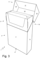
- the outer container 2 has an open upper end and is provided with a lid 4, which is cup-shaped and is hinged to the outer container 2 along a hinge 5 (illustrated in Figure 2 ) so as to rotate, relative to said outer container 2, between an open position (illustrated in Figure 3 ) and a closed position (illustrated in Figures 1 and 2 ) of the open upper end.
- the outer container 2 has a substantially rectangular parallelepiped shape oriented according to a direction of prevalent vertical development, is cup-shaped, and has the open upper end, a lower wall 6 opposite the open upper end, a front wall 7 and a rear wall 8 (in which the hinge 5 is formed) parallel to and opposite each other, and two side walls 9 parallel to and opposite each other.
- the lid 4 has a substantially rectangular parallelepiped shape, is cup-shaped, and has an open lower end (facing the open upper end of the outer container 2 when the lid 4 is in the closed position), an upper wall 10 (which is parallel to and opposite the lower wall 6 of the outer container 2 when the lid 4 is in the closed position), a front wall 11 (which is parallel to and aligned with the front wall 7 of the outer container 2 when the lid 4 is in the closed position), a rear wall 12 (which is parallel to and aligned with the rear wall 8 of the outer container 2 when the lid 4 is in the closed position and is hinged to the rear wall 8 of the outer container 2 along the hinge 5), and two side walls 13 parallel to and opposite each other (which are parallel to and aligned with, in particular coplanar and adjacent to, the side walls 9 of the outer container 2 when the lid 4 is in the closed position).
- the wrap 3 encloses a group 14 of cigarettes (illustrated in Figure 5 ) of a parallelepiped shape.
- the pack 1 of cigarettes further comprises a rigid collar 15, which is connected (by means of gluing) folded in a "U"-shape to the inside of the outer container 2 so as to partially protrude outside the open upper end of the outer container 2 and engage a corresponding inner surface of the lid 4 when said lid 4 is arranged in the closed position.
- the outer container 2 and the lid 4 are obtained by folding a blank 16 of a conventional type, wherein each side wall 9 of the outer container 2 is obtained by superimposing and gluing two wings 9' and 9" and each side wall 13 of the lid 4 is obtained by superimposing and gluing two wings 13' and 13".
- the front wall 11 of the lid 4 is formed by superimposing and gluing a panel 11' and a flap 11".
- the blank 16 has two pre-weakened longitudinal folding lines (which define the longitudinal edges of the outer container 2 and of the lid 4) and a plurality of pre-weakened transverse folding lines (which define the transverse edges of the outer container 2 and of the lid 4) which delimit, between the two longitudinal folding lines, a panel 7' which constitutes the front wall 7 of the outer container 2, a panel 6' which constitutes the lower wall 6 of the outer container 2, a panel 8' which constitutes the rear wall 8 of the outer container 2, a panel 12' which constitutes the rear wall 12 of the lid 4, a panel 10' which constitutes the upper wall 10 of the lid 4, a panel 11' which constitutes the front wall 11 of the lid 4, and a panel 11" which constitutes the reinforcement flap and which is folded by 180° and glued against an inner surface of the panel 11' (i.e. against an inner surface of the front wall 11 of the lid 4).
- the blank 16 comprises a pair of wings 9', which are arranged on opposite sides of the panel 7', are connected to the panel 7' along the two longitudinal folding lines, and constitute part of the side walls 9 of the outer container 2.
- the blank 16 comprises a pair of wings 9", which are arranged on opposite sides of the panel 8', are connected to the panel 8' along the two longitudinal folding lines, constitute part of the side walls 9 of the outer container 2, and are glued and superimposed on the corresponding outer wings 9'.
- Each wing 9" comprises a tab which is folded by 90° with respect to the wing 9" in order to then be rested against and glued to the panel 6'.
- the blank 16 comprises a pair of wings 13', which are arranged on opposite sides of the panel 11', are connected to the panel 11' along the two longitudinal folding lines, and constitute part of the side walls 13 of the lid 4.
- the blank 16 comprises a pair of wings 13", which are arranged on opposite sides of the panel 12', are connected to the panel 12' along the two longitudinal folding lines, constitute part of the side walls 13 of the lid 4, and are glued to and superimposed on the corresponding outer wings 13'.
- Each wing 13" comprises a tab which is folded by 90° with respect to the wing 13" in order to then be rested against and glued to the panel 10'.
- the reference number 17 indicates, as a whole, a packer machine (only partially illustrated in Figure 7 ) which is designed to produce the pack 1 of cigarettes described above and operates with an intermittent motion (i.e. a motion involving a cyclical alternation of phases of motion and phases of rest).
- an intermittent motion i.e. a motion involving a cyclical alternation of phases of motion and phases of rest.
- a final part of the packer machine 17 comprises a wrapping drum 18 (i.e. a wrap conveyor), which is mounted so as to be rotatable (with an intermittent motion, i.e. "in steps") around a horizontal rotation axis 19.
- the wrapping drum 18 supports twelve pockets 20, each of which is designed to accommodate inside it a wrap 3 coupled to a collar 15 and to a blank 16.
- the rotation of the wrapping drum 18 around the rotation axis 19 cyclically moves each pocket 20 along a circular wrapping path and through an input station, in which a wrap 3, a collar 15 and a blank 16 are inserted radially (i.e. perpendicular to the rotation axis 19) inside the pocket 20 (when entering the pocket 20, the blank 16 is folded in a "U" shape around the wrap 3 and the collar 15), and then through a transfer station S1, in which the almost complete pack 1 of cigarettes is extracted radially (i.e. perpendicularly to the rotation axis 19) from the pocket 20.
- a folding device 21 Arranged downstream of the input station S1 is a folding device 21 (provided only with fixed folding elements, which lack moving parts and are arranged along the wrapping path), which folds the blank 16 around the wrap 3 and the collar 15 so as to obtain (at the transfer station S 1) the configuration illustrated in Figure 7 , in which, in order to complete the pack 1 of cigarettes, the wings 9' and 13' need to be folded by 90° against the previously folded wings 9" and 13" (in particular when the blank 16 enters a pocket 20 together with a wrap 3 and a collar 15).
- an almost complete pack 1 of cigarettes i.e. a wrap 3 together with a corresponding collar 15 and a corresponding blank 16 almost completely folded around the wrap 3 and with the wings 9' and 13' yet to be folded
- a pushing member 22 which is located inside the wrapping drum 18
- an accompanying member 23 which is located outside the wrapping drum 18
- is then extracted from the respective pocket 20 of the wrapping drum 18 by means of a radial motion i.e. perpendicular to the rotation axis 19
- an extraction path P1 extends from the transfer station S1 (which is located inside the wrapping drum 18 and begins at a pocket 20 of the wrapping drum 18) to a transfer station S2 (which is located outside the wrapping drum 18).
- Two pushing members 24 (which operate cyclically in alternation) are provided, each of which pushing an almost complete pack 1 of cigarettes (i.e. a wrap 3 together with a corresponding collar 15 and a corresponding blank 16 almost completely folded around the wrap 3 and with the wings 9' and 13' yet to be folded) from the transfer station S2 to a transfer station S3 and along a horizontal, straight gluing path P2 perpendicular to the extraction path P1, and parallel to the rotation axis 19 of the wrapping drum 18 (i.e. perpendicular to the wrapping path of the wrapping drum 18).
- the two pushing members 24 have an alternating motion (i.e.
- gluing devices 25 Arranged along the straight gluing path P2 are two gluing devices 25 which apply glue 26 (typically hot glue, i.e. quick-setting glue) on the wings 9' and 13' yet to be folded of each blank 16; in other words, a pair of gluing devices 25 is provided arranged on opposite sides of the gluing path P2.
- the straight gluing path P2 runs from the transfer station S2, in which each almost complete pack 1 of cigarettes has just emerged from the wrapping drum 18, to the transfer station S3, in which each almost complete and glued (i.e. provided with glue 26) pack 1 of cigarettes is ready to be completed (i.e. to fold the wings 9' and 13' provided with glue 26 against the corresponding wings 9" and 13").
- a pushing member 27 is provided which pushes an almost complete pack 1 of cigarettes (i.e. a wrap 3 together with a corresponding collar 15 and a corresponding blank 16 almost completely folded around the wrap 3 and with the wings 9' and 13' yet to be folded) from the transfer station S3 to a transfer station S4 and along a horizontal, straight insertion path P3 perpendicular to the gluing path P2 and parallel to the extraction path P1.
- the pushing member 27 cooperates with an accompanying member 28 in such a manner that the pushing member 27 and the accompanying member 28 clamp a pack 1 of cigarettes between them.
- the folding device 29 Arranged along the straight insertion path P3 is a folding device 29, which folds the wings 9' and 13' by 90° against the previously folded wings 9" and 13", thus completing the creation of the pack 1 of cigarettes.
- the folding device 29 comprises only fixed folding elements, which lack moving parts and are arranged along the insertion path P3; in particular, the folding device 29 consists of a ring with a rectangular shape, through which the packs 1 of cigarettes are made to pass.
- the straight insertion path P3 runs from the transfer station S3, in which an almost complete and glued (i.e. provided with glue 26) pack 1 of cigarettes arrives, to the transfer station S4, in which a complete pack 1 of cigarettes arrives (i.e. in which all folding operations have been completed).
- the packer machine 17 comprises a stabilization drum 30 (i.e. a stabilization conveyor 30), which is mounted so as to rotate (with an intermittent motion, i.e. "in steps") around a rotation axis 31 parallel to the rotation axis 19 of the wrapping drum 18.
- the stabilization drum 30 supports twelve pockets 32, each of which being designed to accommodate inside it a complete pack 1 of cigarettes.
- the rotation of the stabilization drum 30 around the rotation axis 31 cyclically moves each pocket 32 along a circular stabilization path which extends from the transfer station S4, in which the pocket 32 receives the complete pack 1 of cigarettes directly from the pushing member 27 (which cooperates with the accompanying member 28), and a transfer station S5, in which the pocket 32 releases the complete pack 1 of cigarettes.
- the packer machine 17 comprises an output conveyor 33, which is configured to receive the pack 1 of cigarettes from the stabilization drum 30 in the transfer station S5 and to move the pack 1 of cigarettes along a straight and vertical outlet path.
- the output conveyor 33 comprises a conveyor belt arranged vertically and wrapped around two end pulleys.
- a pushing member 34 (potentially cooperating with an accompanying member) is arranged in the transfer station S5, which pushing member 34 extracts a complete pack 1 of cigarettes from a pocket 32 of the stabilization drum 30 and inserts it into the output conveyor 33.
- the packer machine 17 comprises a restraining device 35, which is arranged in the transfer station S2 and comprises two restraining elements 36, which are movable along a gripping direction D perpendicular to the extraction path P1 between an active position (illustrated in Figure 8 ), in which the two restraining elements 36 rest against the wings 9" and 13" of the pack 1 of cigarettes located in the transfer station S2, and a rest position (illustrated in Figure 9 ), in which the two restraining elements 36 are spaced apart from the wings 9" and 13" of the pack 1 of cigarettes located in the transfer station S2.
- the restraining device 35 holds the restraining elements 36 in the rest position (illustrated in Figure 9 ) while the pushing member 22 pushes the almost complete pack 1 of cigarettes from the transfer station S1 to the transfer station S2, then the restraining device 35 moves the restraining elements 36 to the active position (illustrated in Figure 8 ) when the almost complete pack 1 of cigarettes is in the transfer station S2, and the restraining device 35 holds the restraining elements 36 in the active position (illustrated in Figure 8 ) while a pushing member 24 pushes the almost complete pack 1 of cigarettes from the transfer station S2 to the transfer station S3 along the gluing path P2
- the pushing member 22 is "U"-shaped and has a base wall 37 and two side walls 38, which are arranged on opposite sides of the base wall 37 and are configured to rest against the wings 9" and 13" of the almost complete pack 1 of cigarettes.
- Each restraining element 36 has a shape that is complementary to a shape of a respective side wall 38 of the pushing member 22 so that it can rest against the corresponding wings 9" and 13" of the almost complete pack 1 of cigarettes located in the transfer station S2 together with the respective side wall 38 of the pushing member 22; in other words, for an instant, the wings 9" and 13" of the almost complete pack 1 of cigarettes which is located in the transfer station S2 are engaged at the same time by both the side walls 38 of the pushing member 22 and the restraining elements 36 and in this manner the wings 9" and 13" of the pack 1 of cigarettes are always held in the correct position (i.e. they are never relinquished and thus can never be moved in an undesirable manner).
- the restraining device 35 comprises a single common guide 39 oriented parallel to the gripping direction D; in particular, the single common guide 39 is divided into two sections coaxial to each other and separated by an intermediate gap.
- the restraining device 35 comprises two slides 40, each being mounted so as to be slidable on the guide 39 and supporting a corresponding restraining element 36; in particular, a bracket 41 is mounted on each slide 40 to which bracket 41 the corresponding restraining element 36 is fixed.
- the restraining device 35 comprises an actuator device 42, which cyclically moves the slides 40 back and forth along the guide 39; in other words, the slides 40 are moved closer to each other to move the restraining elements 36 to the active position (illustrated in Figure 8 ) and the slides 40 are moved away from each other to move the restraining elements 36 to the rest position (illustrated in Figure 9 ).
- the actuator device 42 comprises a shaft 43 mounted so as to be rotatable about a rotation axis (perpendicular to the gripping direction D), an electric motor 44 configured to rotate the shaft 43 with a reciprocating motion in both rotation directions, and two connecting-rod/crank mechanisms, each comprising a crank 45 fixed to the shaft 43 and a connecting rod 46 connected to a corresponding slide 40.
- a shaft of the electric motor 45 is not fixed to the shaft 43 directly but transmits motion to the shaft 43 by means of a coupling 47; thereby, the electric motor 45 is parallel to the shaft 43 but not coaxial to the shaft 43.
- Figure 13 illustrates a movement system 48 for moving the accompanying member 23 which cooperates with the pushing member 22.
- the movement system 48 comprises a guide 49, a slide 50 which is mounted so as to be slidable on the guide 49 and supporting the accompanying member 23, and an electric motor 51 which alternatively moves the slide 50 along the guide 49 by means of a mechanical transmission.
- each pushing member 24 (only one of which is illustrated in Figures 14 , 15 and 16 for the sake of clarity) is operated by a respective actuator device 52.
- the two actuator devices 52 are configured to operate the two pushing members 24 alternatively in such a manner that, while one pushing member 24 performs a forward stroke to push the wrap 3 wrapped in the blank 16 from the transfer station S2 to the transfer station S3 along the gluing path P2, the other pushing member 24 performs a return stroke to return from the transfer station S3 to the transfer station S2 outside the gluing path P2.
- Each pushing member 24 is mounted so as to be rotatable around a respective rotation axis 53 parallel to the gluing path P2 in order to rotate between a forward position (in order to perform the forward stroke and move an almost complete pack 1 of cigarettes), in which the pushing member 24 is located along the gluing path P2, and a return position (in order to perform the return stroke without interfering with an almost complete pack 1 of cigarettes), in which the pushing member 24 is outside the gluing path P2.
- each actuator device 52 comprises a shaft 57, which is mounted so as to be rotatable around a rotation axis 58 (parallel to and spaced apart from the rotation axis 53 and thus parallel to the gluing path P2) and is brought into rotation by the electric motor 56.
- the shaft 57 supports two cams 59 and 60, which rotate integrally with the shaft 57 and generate the thrust for driving both the rotation of the guide 54 and the sliding of the slide 55.
- Each actuator device 52 comprises a transmission 61 which, by means of the cam 59, receives the motion from the shaft 57 to rotate the respective guide 54 around the corresponding rotation axis 53; analogously, each actuator device 52 comprises a transmission 62 which, by means of the cam 60, receives the motion from the shaft 57 to push the corresponding slide 55 along the respective guide 54.
- the movement of the various components (wrapping drums, feeding conveyors, pushing members, movable folding devices...) of the packer machine 17 is provided by means of respective electric motors which are mechanically independent of one another and are synchronized (i.e. moved in phase) in a virtual manner (i.e. not by a physical constraint, but by a control constraint).
- respective electric motors which are mechanically independent of one another and are synchronized (i.e. moved in phase) in a virtual manner (i.e. not by a physical constraint, but by a control constraint).
- Normally an electric motor is considered a reference (“master”) and all other electric motors (“slaves”) follow the position of the reference electric motor (“master").
- a rotating electric motor which causes the rotation of a pinion which meshes with a rack; in other words, a "pinion-rack” mechanism is used for transforming the rotary movement generated by the electric motor into a linear movement.
- the packer machine 17 described in the foregoing has numerous advantages. First of all, the packer machine 17 described in the foregoing makes it possible to complete the manufacturing of the outer container 2 and lid 4 while guaranteeing a high production quality even when operating at a high production speed (i.e. with a high number of packs 1 of cigarettes produced in a unit of time).
- the gluing of the wings 9' and 13' of each pack 1 of cigarettes occurs in a very precise manner (thus preventing that glue 26 ends up on visible surfaces of the pack 1 of cigarettes or parts of the packer machine 17 arranged closed to the gluing devices 25) and reliably (thus preventing that a pack 1 of cigarettes can " open up " later on or lose its shape).
- the packer machine 17 described in the foregoing makes it possible to change the format of the packs 1 of cigarettes relatively easily and quickly.
- the packer machine 17 described in the foregoing is relatively compact and provides a good accessibility to all its components; in fact, an operator located in front of the packer machine 17 is able to manually reach all active parts of the packer machine 17 in a simple, quick and ergonomic manner.
- the embodiment illustrated in the accompanying figures relates to the manufacturing of a pack of cigarettes, but the present invention is also applicable without substantial modifications to the manufacturing of any other kind of pack of smoking articles (for example, a pack of cigars, a pack of electronic cigarettes of the liquid-vaporization type, a pack of next-generation cigarettes without the combustion of tobacco).
- a pack of cigars for example, a pack of cigars, a pack of electronic cigarettes of the liquid-vaporization type, a pack of next-generation cigarettes without the combustion of tobacco.
Landscapes
- Engineering & Computer Science (AREA)
- Mechanical Engineering (AREA)
- Wrapping Of Specific Fragile Articles (AREA)
Abstract
A packer machine (17) and wrapping method to obtain a pack (1) of cigarettes provided with an outer container (2) and with a hinged lid (4) by folding a blank (16) around a wrap (3) enclosing a group (14) of smoking articles. The invention includes: a wrapping drum (18), which moves a pocket (20) configured to contain the wrap (3) and the blank (16) towards a first transfer station (S1); a first folding device (21), which is coupled to the wrapping drum (18) and is configured to fold the blank (16) around the wrap (3) by placing a pair of second wings (9", 13") in contact with the wrap (3) and placing a pair of first wings (9', 13') coplanar to one another and perpendicular to the pair of second wings (9", 13"); a first pushing member (22) configured to extract the wrap (3) wrapped in the blank (16) from the first pocket (20) of the wrapping drum (18) by means of a movement along an extraction path (P1), which extends from the first transfer station (S 1) to a second transfer station (S2); a second pushing member (24) configured to push the wrap (3) wrapped in the blank (16) from the second transfer station (S2) to a third transfer station (S3) and along a straight gluing path (P2); at least one gluing device (25), which is arranged along the gluing path (P2) and applies glue (26) on the first wings (9', 13') or on the second wings (9", 13"); a third pushing member (27) configured to push the wrap (3) wrapped in the blank (16) from the third transfer station (S3) to a fourth transfer station (S4) and along an insertion path (P3); and a second folding device (29), which is arranged along the insertion path (P3) and folds the first wings (9', 13') by 90° against the second wings (9", 13"), thus completing the creation of the pack (1) of cigarettes.
Description
- This patent application claims priority from
Italian patent application no. 102023000007542 filed on April 18, 2023 - The present invention relates to a packer machine and a wrapping method to obtain a pack of cigarettes provided with an outer container and a hinged lid by folding a blank around a wrap enclosing a group of smoking articles.
- The present invention can be advantageously applied to the manufacturing of a pack of cigarettes containing a group of cigarettes, to which the following discussion will explicitly refer without thereby losing generality.
- Rigid packs of cigarettes with hinged lids are the most common packs of cigarettes currently on the market since they are easy to obtain, are easy and convenient to use, and offer good protection to the cigarettes contained inside them.
- A rigid pack of cigarettes with a hinged lid comprises a wrap consisting of a group of cigarettes wrapped in a sheet of metalized paper and a rigid outer casing which houses the wrap inside it. The outer casing consists of a cup-shaped container, which houses the group of cigarettes and has an open top end, and a lid, which is also cup-shaped and is hinged to the container so as to rotate, relative to said container, between an open position and a closed position of the open end.
- The patent applications
EP3546377A1 ,EP3546378A1 andEP3546379A1 describe a packer machine to obtain a pack of cigarettes provided with an outer container and with a hinged lid by folding a blank around a wrap enclosing a group of cigarettes. The packer machine comprises: a wrapping drum, which moves a pocket along a circular wrapping path; a first folding device, which is arranged along the wrapping path and folds the blank around the wrap by placing a pair of second wings in contact with the wrap and by placing a pair of first wings coplanar to one another and perpendicular to the pair of second wings; a pushing member, which extracts the wrap wrapped in the blank from the pocket of the wrapping drum by means of a movement along a transfer direction, which is perpendicular to the wrapping path; a gluing conveyor, which receives the wrap wrapped in the blank from the pocket of the wrapping drum and moves the wrap wrapped in the blank along a straight gluing path arranged parallel to a rotation axis of the wrapping drum; a gluing device, which is arranged along the gluing path and applies glue on the first wings; and a second folding device, which is arranged downstream of the gluing device and folds the first wings 90° against the second wings, thus completing the manufacturing of the pack of cigarettes. - The object of the present invention is to provide a packer machine and a wrapping method to obtain a packet of cigarettes provided with an outer container and with a hinged lid by folding a blank around a wrap enclosing a group of smoking articles, which packer machine and wrapping method make it possible to obtain a high-quality wrap even when operating at a high production speed (measured as packs of cigarettes produced in the unit of time).
- According to the present invention, a packer machine and a wrapping method are provided to obtain a pack of cigarettes provided with an outer container and with a hinged lid by folding a blank around a wrap enclosing a group of smoking articles as claimed in the appended claims.
- The claims describe embodiments of the present invention and form an integral part of the present description.
- The present invention will now be described with reference to the accompanying drawings, which illustrate a non-limiting example embodiment thereof, wherein:
-
Figure 1 is a front perspective view of a rigid pack of cigarettes in a closed configuration; -
Figure 2 is a rear perspective view of the pack of cigarettes ofFigure 1 in a closed configuration; -
Figure 3 is a front perspective view of the packet of cigarettes ofFigure 1 in an open configuration; -
Figure 4 is a front perspective view of a wrap of the pack ofFigure 1 ; -
Figure 5 is a perspective view of a group of cigarettes contained in the wrap ofFigure 4 ; -
Figure 6 is a plan view of a blank used to obtain an outer container provided with a hinged lid of the pack of cigarettes ofFigure 1 ; -
Figure 7 is a schematic view of a final part of a packer machine which produces the pack of cigarettes ofFigure 1 and which is provided according to the present invention; -
Figures 8 and 9 are two different schematic views of two restraining elements of the packer machine ofFigure 1 ; -
Figures 10 and 11 are two different perspective views of a pushing member, of an accompanying member and of the two restraining elements of the packer machine ofFigure 1 ; -
Figure 12 is a perspective view of a movement system for moving the two restraining elements ofFigures 8-11 . -
Figure 13 is a perspective view of a movement system for moving the accompanying member ofFigures 10-11 ; and -
Figures 14 ,15 and16 are three different perspective views of a movement system for moving a further pushing member of the packer machine ofFigure 1 . - In
Figures 1, 2 and3 , thereference number 1 indicates, as a whole, a rigid pack of cigarettes. Thepack 1 of cigarettes comprises a cup-shapedouter container 2 made of cardboard or rigid paperboard and a wrap 3 (better illustrated inFigure 4 ) housed inside thecontainer 2. - The
outer container 2 has an open upper end and is provided with alid 4, which is cup-shaped and is hinged to theouter container 2 along a hinge 5 (illustrated inFigure 2 ) so as to rotate, relative to saidouter container 2, between an open position (illustrated inFigure 3 ) and a closed position (illustrated inFigures 1 and 2 ) of the open upper end. Theouter container 2 has a substantially rectangular parallelepiped shape oriented according to a direction of prevalent vertical development, is cup-shaped, and has the open upper end, alower wall 6 opposite the open upper end, afront wall 7 and a rear wall 8 (in which the hinge 5 is formed) parallel to and opposite each other, and twoside walls 9 parallel to and opposite each other. - The
lid 4 has a substantially rectangular parallelepiped shape, is cup-shaped, and has an open lower end (facing the open upper end of theouter container 2 when thelid 4 is in the closed position), an upper wall 10 (which is parallel to and opposite thelower wall 6 of theouter container 2 when thelid 4 is in the closed position), a front wall 11 (which is parallel to and aligned with thefront wall 7 of theouter container 2 when thelid 4 is in the closed position), a rear wall 12 (which is parallel to and aligned with therear wall 8 of theouter container 2 when thelid 4 is in the closed position and is hinged to therear wall 8 of theouter container 2 along the hinge 5), and twoside walls 13 parallel to and opposite each other (which are parallel to and aligned with, in particular coplanar and adjacent to, theside walls 9 of theouter container 2 when thelid 4 is in the closed position). - The
wrap 3 encloses agroup 14 of cigarettes (illustrated inFigure 5 ) of a parallelepiped shape. - As is illustrated in
Figure 3 , thepack 1 of cigarettes further comprises arigid collar 15, which is connected (by means of gluing) folded in a "U"-shape to the inside of theouter container 2 so as to partially protrude outside the open upper end of theouter container 2 and engage a corresponding inner surface of thelid 4 when saidlid 4 is arranged in the closed position. - As is illustrated in
Figure 6 , theouter container 2 and thelid 4 are obtained by folding a blank 16 of a conventional type, wherein eachside wall 9 of theouter container 2 is obtained by superimposing and gluing twowings 9' and 9" and eachside wall 13 of thelid 4 is obtained by superimposing and gluing twowings front wall 11 of thelid 4 is formed by superimposing and gluing a panel 11' and aflap 11". - In particular, the blank 16 has two pre-weakened longitudinal folding lines (which define the longitudinal edges of the
outer container 2 and of the lid 4) and a plurality of pre-weakened transverse folding lines (which define the transverse edges of theouter container 2 and of the lid 4) which delimit, between the two longitudinal folding lines, a panel 7' which constitutes thefront wall 7 of theouter container 2, a panel 6' which constitutes thelower wall 6 of theouter container 2, a panel 8' which constitutes therear wall 8 of theouter container 2, a panel 12' which constitutes therear wall 12 of thelid 4, a panel 10' which constitutes theupper wall 10 of thelid 4, a panel 11' which constitutes thefront wall 11 of thelid 4, and apanel 11" which constitutes the reinforcement flap and which is folded by 180° and glued against an inner surface of the panel 11' (i.e. against an inner surface of thefront wall 11 of the lid 4). - The blank 16 comprises a pair of wings 9', which are arranged on opposite sides of the panel 7', are connected to the panel 7' along the two longitudinal folding lines, and constitute part of the
side walls 9 of theouter container 2. The blank 16 comprises a pair ofwings 9", which are arranged on opposite sides of the panel 8', are connected to the panel 8' along the two longitudinal folding lines, constitute part of theside walls 9 of theouter container 2, and are glued and superimposed on the corresponding outer wings 9'. Eachwing 9" comprises a tab which is folded by 90° with respect to thewing 9" in order to then be rested against and glued to the panel 6'. - The blank 16 comprises a pair of
wings 13', which are arranged on opposite sides of the panel 11', are connected to the panel 11' along the two longitudinal folding lines, and constitute part of theside walls 13 of thelid 4. The blank 16 comprises a pair ofwings 13", which are arranged on opposite sides of the panel 12', are connected to the panel 12' along the two longitudinal folding lines, constitute part of theside walls 13 of thelid 4, and are glued to and superimposed on the correspondingouter wings 13'. Eachwing 13" comprises a tab which is folded by 90° with respect to thewing 13" in order to then be rested against and glued to the panel 10'. - In
Figure 7 , thereference number 17 indicates, as a whole, a packer machine (only partially illustrated inFigure 7 ) which is designed to produce thepack 1 of cigarettes described above and operates with an intermittent motion (i.e. a motion involving a cyclical alternation of phases of motion and phases of rest). - A final part of the
packer machine 17 comprises a wrapping drum 18 (i.e. a wrap conveyor), which is mounted so as to be rotatable (with an intermittent motion, i.e. "in steps") around ahorizontal rotation axis 19. The wrappingdrum 18 supports twelvepockets 20, each of which is designed to accommodate inside it awrap 3 coupled to acollar 15 and to a blank 16. - The rotation of the wrapping
drum 18 around therotation axis 19 cyclically moves eachpocket 20 along a circular wrapping path and through an input station, in which awrap 3, acollar 15 and a blank 16 are inserted radially (i.e. perpendicular to the rotation axis 19) inside the pocket 20 (when entering thepocket 20, the blank 16 is folded in a "U" shape around thewrap 3 and the collar 15), and then through a transfer station S1, in which the almostcomplete pack 1 of cigarettes is extracted radially (i.e. perpendicularly to the rotation axis 19) from thepocket 20. - Arranged downstream of the input station S1 is a folding device 21 (provided only with fixed folding elements, which lack moving parts and are arranged along the wrapping path), which folds the blank 16 around the
wrap 3 and thecollar 15 so as to obtain (at the transfer station S 1) the configuration illustrated inFigure 7 , in which, in order to complete thepack 1 of cigarettes, thewings 9' and 13' need to be folded by 90° against the previously foldedwings 9" and 13" (in particular when the blank 16 enters apocket 20 together with awrap 3 and a collar 15). - In the transfer station S1, an almost
complete pack 1 of cigarettes (i.e. awrap 3 together with acorresponding collar 15 and a corresponding blank 16 almost completely folded around thewrap 3 and with thewings 9' and 13' yet to be folded) is "clamped" (i.e. grasped) between a pushing member 22 (which is located inside the wrapping drum 18) and an accompanying member 23 (which is located outside the wrapping drum 18) and is then extracted from therespective pocket 20 of the wrappingdrum 18 by means of a radial motion (i.e. perpendicular to the rotation axis 19) and along an extraction path P1, which is horizontal and perpendicular to the wrapping path and to therotation axis 19. In particular, the extraction path P1 extends from the transfer station S1 (which is located inside the wrappingdrum 18 and begins at apocket 20 of the wrapping drum 18) to a transfer station S2 (which is located outside the wrapping drum 18). - Two pushing members 24 (which operate cyclically in alternation) are provided, each of which pushing an almost
complete pack 1 of cigarettes (i.e. awrap 3 together with acorresponding collar 15 and a corresponding blank 16 almost completely folded around thewrap 3 and with thewings 9' and 13' yet to be folded) from the transfer station S2 to a transfer station S3 and along a horizontal, straight gluing path P2 perpendicular to the extraction path P1, and parallel to therotation axis 19 of the wrapping drum 18 (i.e. perpendicular to the wrapping path of the wrapping drum 18). The two pushingmembers 24 have an alternating motion (i.e. with a cyclical alternation of forward strokes and return strokes) along the straight gluing path P2 and alternate in such a manner that, while one pushingmember 24 performs a forward stroke to push an almostcomplete pack 1 of cigarettes from the transfer station S2 to the transfer station S3 along the gluing path P2, the other pushingmember 24 performs a return stroke to return from the transfer station S3 to the transfer station S2 outside the gluing path P2. - Arranged along the straight gluing path P2 are two
gluing devices 25 which apply glue 26 (typically hot glue, i.e. quick-setting glue) on thewings 9' and 13' yet to be folded of each blank 16; in other words, a pair ofgluing devices 25 is provided arranged on opposite sides of the gluing path P2. The straight gluing path P2 runs from the transfer station S2, in which each almostcomplete pack 1 of cigarettes has just emerged from the wrappingdrum 18, to the transfer station S3, in which each almost complete and glued (i.e. provided with glue 26)pack 1 of cigarettes is ready to be completed (i.e. to fold thewings 9' and 13' provided withglue 26 against thecorresponding wings 9" and 13"). - A pushing
member 27 is provided which pushes an almostcomplete pack 1 of cigarettes (i.e. awrap 3 together with acorresponding collar 15 and acorresponding blank 16 almost completely folded around thewrap 3 and with thewings 9' and 13' yet to be folded) from the transfer station S3 to a transfer station S4 and along a horizontal, straight insertion path P3 perpendicular to the gluing path P2 and parallel to the extraction path P1. The pushingmember 27 cooperates with an accompanyingmember 28 in such a manner that the pushingmember 27 and the accompanyingmember 28 clamp apack 1 of cigarettes between them. - Arranged along the straight insertion path P3 is a
folding device 29, which folds thewings 9' and 13' by 90° against the previously foldedwings 9" and 13", thus completing the creation of thepack 1 of cigarettes. According to a preferred embodiment illustrated in the accompanying figures, thefolding device 29 comprises only fixed folding elements, which lack moving parts and are arranged along the insertion path P3; in particular, thefolding device 29 consists of a ring with a rectangular shape, through which thepacks 1 of cigarettes are made to pass. The straight insertion path P3 runs from the transfer station S3, in which an almost complete and glued (i.e. provided with glue 26)pack 1 of cigarettes arrives, to the transfer station S4, in which acomplete pack 1 of cigarettes arrives (i.e. in which all folding operations have been completed). - The
packer machine 17 comprises a stabilization drum 30 (i.e. a stabilization conveyor 30), which is mounted so as to rotate (with an intermittent motion, i.e. "in steps") around arotation axis 31 parallel to therotation axis 19 of thewrapping drum 18. Thestabilization drum 30 supports twelvepockets 32, each of which being designed to accommodate inside it acomplete pack 1 of cigarettes. The rotation of thestabilization drum 30 around therotation axis 31 cyclically moves eachpocket 32 along a circular stabilization path which extends from the transfer station S4, in which thepocket 32 receives thecomplete pack 1 of cigarettes directly from the pushing member 27 (which cooperates with the accompanying member 28), and a transfer station S5, in which thepocket 32 releases thecomplete pack 1 of cigarettes. - The wrapping
drum 18 and thestabilization drum 30 are parallel to one another as well as staggered and are located at a mutual axial distance, which is equal to the extension of the gluing path P2. - The
packer machine 17 comprises an output conveyor 33, which is configured to receive thepack 1 of cigarettes from thestabilization drum 30 in the transfer station S5 and to move thepack 1 of cigarettes along a straight and vertical outlet path. According to a preferred embodiment, the output conveyor 33 comprises a conveyor belt arranged vertically and wrapped around two end pulleys. In particular, a pushing member 34 (potentially cooperating with an accompanying member) is arranged in the transfer station S5, which pushingmember 34 extracts acomplete pack 1 of cigarettes from apocket 32 of thestabilization drum 30 and inserts it into the output conveyor 33. According to a preferred embodiment illustrated inFigures 8-12 , thepacker machine 17 comprises a restrainingdevice 35, which is arranged in the transfer station S2 and comprises two restrainingelements 36, which are movable along a gripping direction D perpendicular to the extraction path P1 between an active position (illustrated inFigure 8 ), in which the tworestraining elements 36 rest against thewings 9" and 13" of thepack 1 of cigarettes located in the transfer station S2, and a rest position (illustrated inFigure 9 ), in which the tworestraining elements 36 are spaced apart from thewings 9" and 13" of thepack 1 of cigarettes located in the transfer station S2. - In use, the restraining
device 35 holds therestraining elements 36 in the rest position (illustrated inFigure 9 ) while the pushingmember 22 pushes the almostcomplete pack 1 of cigarettes from the transfer station S1 to the transfer station S2, then the restrainingdevice 35 moves therestraining elements 36 to the active position (illustrated inFigure 8 ) when the almostcomplete pack 1 of cigarettes is in the transfer station S2, and the restrainingdevice 35 holds therestraining elements 36 in the active position (illustrated inFigure 8 ) while a pushingmember 24 pushes the almostcomplete pack 1 of cigarettes from the transfer station S2 to the transfer station S3 along the gluing path P2 According to a preferred embodiment, the pushingmember 22 is "U"-shaped and has abase wall 37 and twoside walls 38, which are arranged on opposite sides of thebase wall 37 and are configured to rest against thewings 9" and 13" of the almostcomplete pack 1 of cigarettes. Each restrainingelement 36 has a shape that is complementary to a shape of arespective side wall 38 of the pushingmember 22 so that it can rest against the correspondingwings 9" and 13" of the almostcomplete pack 1 of cigarettes located in the transfer station S2 together with therespective side wall 38 of the pushingmember 22; in other words, for an instant, thewings 9" and 13" of the almostcomplete pack 1 of cigarettes which is located in the transfer station S2 are engaged at the same time by both theside walls 38 of the pushingmember 22 and therestraining elements 36 and in this manner thewings 9" and 13" of thepack 1 of cigarettes are always held in the correct position (i.e. they are never relinquished and thus can never be moved in an undesirable manner). - As illustrated in
Figure 12 , the restrainingdevice 35 comprises a singlecommon guide 39 oriented parallel to the gripping direction D; in particular, the singlecommon guide 39 is divided into two sections coaxial to each other and separated by an intermediate gap. In addition, the restrainingdevice 35 comprises twoslides 40, each being mounted so as to be slidable on theguide 39 and supporting a corresponding restrainingelement 36; in particular, abracket 41 is mounted on eachslide 40 to whichbracket 41 the corresponding restrainingelement 36 is fixed. Finally, the restrainingdevice 35 comprises anactuator device 42, which cyclically moves theslides 40 back and forth along theguide 39; in other words, theslides 40 are moved closer to each other to move therestraining elements 36 to the active position (illustrated inFigure 8 ) and theslides 40 are moved away from each other to move therestraining elements 36 to the rest position (illustrated inFigure 9 ). - The
actuator device 42 comprises ashaft 43 mounted so as to be rotatable about a rotation axis (perpendicular to the gripping direction D), anelectric motor 44 configured to rotate theshaft 43 with a reciprocating motion in both rotation directions, and two connecting-rod/crank mechanisms, each comprising a crank 45 fixed to theshaft 43 and a connectingrod 46 connected to acorresponding slide 40. According to a preferred embodiment, a shaft of theelectric motor 45 is not fixed to theshaft 43 directly but transmits motion to theshaft 43 by means of acoupling 47; thereby, theelectric motor 45 is parallel to theshaft 43 but not coaxial to theshaft 43. -
Figure 13 illustrates amovement system 48 for moving the accompanyingmember 23 which cooperates with the pushingmember 22. Themovement system 48 comprises aguide 49, aslide 50 which is mounted so as to be slidable on theguide 49 and supporting the accompanyingmember 23, and anelectric motor 51 which alternatively moves theslide 50 along theguide 49 by means of a mechanical transmission. - As illustrated in
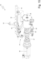
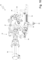
Figures 14 ,15 and16 , each pushing member 24 (only one of which is illustrated inFigures 14 ,15 and16 for the sake of clarity) is operated by arespective actuator device 52. The twoactuator devices 52 are configured to operate the two pushingmembers 24 alternatively in such a manner that, while one pushingmember 24 performs a forward stroke to push thewrap 3 wrapped in the blank 16 from the transfer station S2 to the transfer station S3 along the gluing path P2, the other pushingmember 24 performs a return stroke to return from the transfer station S3 to the transfer station S2 outside the gluing path P2. - Each pushing
member 24 is mounted so as to be rotatable around arespective rotation axis 53 parallel to the gluing path P2 in order to rotate between a forward position (in order to perform the forward stroke and move an almostcomplete pack 1 of cigarettes), in which the pushingmember 24 is located along the gluing path P2, and a return position (in order to perform the return stroke without interfering with an almostcomplete pack 1 of cigarettes), in which the pushingmember 24 is outside the gluing path P2. - Each
actuator device 52 comprises aguide 54, which is oriented parallel to the gluing path P2 and is mounted so as to be rotatable around therespective rotation axis 53, and aslide 55, which is mounted so as to be slidable on theguide 54 and supporting a corresponding pushingmember 24. In addition, eachactuator device 52 comprises anelectric motor 56 configured to rotate therespective guide 54 around thecorresponding rotation axis 53 and, at the same time, to push thecorresponding slide 55 along therespective guide 54. - According to a preferred embodiment, each
actuator device 52 comprises ashaft 57, which is mounted so as to be rotatable around a rotation axis 58 (parallel to and spaced apart from therotation axis 53 and thus parallel to the gluing path P2) and is brought into rotation by theelectric motor 56. Theshaft 57 supports twocams shaft 57 and generate the thrust for driving both the rotation of theguide 54 and the sliding of theslide 55. Eachactuator device 52 comprises atransmission 61 which, by means of thecam 59, receives the motion from theshaft 57 to rotate therespective guide 54 around thecorresponding rotation axis 53; analogously, eachactuator device 52 comprises atransmission 62 which, by means of thecam 60, receives the motion from theshaft 57 to push thecorresponding slide 55 along therespective guide 54. - According to a preferred, but non-binding, embodiment, the movement of the various components (wrapping drums, feeding conveyors, pushing members, movable folding devices...) of the
packer machine 17 is provided by means of respective electric motors which are mechanically independent of one another and are synchronized (i.e. moved in phase) in a virtual manner (i.e. not by a physical constraint, but by a control constraint). Normally an electric motor is considered a reference ("master") and all other electric motors ("slaves") follow the position of the reference electric motor ("master"). In order to obtain linear movements (i.e. which provide a movement along a rectilinear trajectory), a rotating electric motor is used which causes the rotation of a pinion which meshes with a rack; in other words, a "pinion-rack" mechanism is used for transforming the rotary movement generated by the electric motor into a linear movement. - The embodiments described herein can be combined with one another without departing from the scope of protection of the present invention.
- The
packer machine 17 described in the foregoing has numerous advantages. First of all, thepacker machine 17 described in the foregoing makes it possible to complete the manufacturing of theouter container 2 andlid 4 while guaranteeing a high production quality even when operating at a high production speed (i.e. with a high number ofpacks 1 of cigarettes produced in a unit of time). - In particular, the gluing of the
wings 9' and 13' of eachpack 1 of cigarettes occurs in a very precise manner (thus preventing thatglue 26 ends up on visible surfaces of thepack 1 of cigarettes or parts of thepacker machine 17 arranged closed to the gluing devices 25) and reliably (thus preventing that apack 1 of cigarettes can "open up" later on or lose its shape). - In addition, the folding of the
wings 9' and 13' of eachpack 1 of cigarettes against the correspondingwings 9" and 13" also occurs with high precision, thus ensuring a very precise shape of both theouter container 2 and thelid 4. - The
packer machine 17 described in the foregoing makes it possible to change the format of thepacks 1 of cigarettes relatively easily and quickly. - Finally, the
packer machine 17 described in the foregoing is relatively compact and provides a good accessibility to all its components; in fact, an operator located in front of thepacker machine 17 is able to manually reach all active parts of thepacker machine 17 in a simple, quick and ergonomic manner. - The embodiment illustrated in the accompanying figures relates to the manufacturing of a pack of cigarettes, but the present invention is also applicable without substantial modifications to the manufacturing of any other kind of pack of smoking articles (for example, a pack of cigars, a pack of electronic cigarettes of the liquid-vaporization type, a pack of next-generation cigarettes without the combustion of tobacco...).
-
- 1 pack of cigarettes
- 2 outer container
- 3 sealed wrap
- 4 lid
- 5 hinge
- 6 lower wall
- 7 front wall
- 8 rear wall
- 9 side walls
- 10 upper wall
- 11 front wall
- 12 rear wall
- 13 side walls
- 14 group of cigarettes
- 15 collar
- 16 blank
- 17 packer machine
- 18 wrapping drum
- 19 rotation axis
- 20 pockets
- 21 folding device
- 22 pushing member
- 23 accompanying member
- 24 pushing member
- 25 gluing device
- 26 glue
- 27 pushing member
- 28 accompanying member
- 29 folding device
- 30 stabilization drum
- 31 rotation axis
- 32 pockets
- 33 output conveyor
- 34 pushing member
- 35 restraining device
- 36 two restraining elements
- 37 base wall
- 38 side walls
- 39 guide
- 40 slides
- 41 bracket
- 42 actuator device
- 43 shaft
- 44 electric motor
- 45 crank
- 46 connecting rod
- 47 coupling
- 48 movement system
- 49 guide
- 50 slide
- 51 electric motor
- 52 actuator device
- 53 rotation axis
- 54 guide
- 55 slide
- 56 electric motor
- 57 shaft
- 58 rotation axis
- 59 cam
- 60 cam
- 61 transmission
- 62 transmission
- P1 extraction path
- P2 gluing path
- P3 insertion path
- P4 extraction path
- S1 transfer station
- S2 transfer station
- S3 transfer station
- S4 transfer station
- S5 transfer station
- D gripping direction
Claims (14)
- A packer machine (17) to obtain a pack (1) of cigarettes provided with an outer container (2) and with a hinged lid (4) by folding a blank (16) around a wrap (3) enclosing a group (14) of smoking articles; the blank (16) comprises a pair of first wings (9', 13') and a pair of second wings (9", 13"), which are superimposed and glued together so as to build respective side walls (9, 13) of the outer container (2) and of the lid (4); the packer machine (17) comprises:a wrapping drum (18), which is mounted so as to be rotatable around a first rotation axis (19) and moves a first pocket (20) configured to contain the wrap (3) and the blank (16) towards a first transfer station (S1);a first folding device (21), which is coupled to the wrapping drum (18) and is configured to fold the blank (16) around the wrap (3), thus forming an almost complete pack (1) of cigarettes, by placing the pair of second wings (9", 13") in contact with the wrap (3) andby placing the pair of first wings (9', 13') coplanar to one another and perpendicular to the pair of second wings (9", 13");a first pushing member (22) configured to extract the wrap (3) wrapped in the blank (16) from the first pocket (20) of the wrapping drum (18) by means of a movement along an extraction path (P1), which is perpendicular to the first rotation axis (19) and extends from the first transfer station (S1) to a second transfer station (S2);a second pushing member (24) configured to push the wrap (3) wrapped in the blank (16) from the second transfer station (S2) to a third transfer station (S3) and along a straight gluing path (P2), which is perpendicular to the extraction path (P1) and parallel to the first rotation axis (19);at least one gluing device (25), which is arranged along the gluing path (P2) and applies glue (26) on the first wings (9', 13') or on the second wings (9", 13");a third pushing member (27) configured to push the wrap (3) wrapped in the blank (16) from the third transfer station (S3) to a fourth transfer station (S4) and along a straight insertion path (P3), which is perpendicular to the gluing path (P2) and parallel to the extraction path (P1); anda second folding device (29), which is arranged along the insertion path (P3) and folds the first wings (9', 13') by 90° against the second wings (9", 13"), thus completing the creation of the pack (1) of cigarettes;
the packer machine (17) is characterized in that it comprises a stabilization drum (30), which is mounted so as to rotate around a second rotation axis (31) parallel to the first rotation axis (19) and moves a second pocket (32), which is configured to contain the pack (1) of cigarettes, between the fourth transfer station (S4), in which the second pocket (32) directly receives the pack (1) of cigarettes from the third pushing member (27), and a fifth transfer station (S5). - The packer machine (17) according to claim 1 and comprising an output conveyor (33), which is configured to receive the pack (1) of cigarettes from the stabilization drum (30) in the fifth transfer station (S5) and to move the pack (1) of cigarettes along a straight and vertical output path.
- The packer machine (17) according to claim 1 or 2, wherein the second folding device (29) only comprises fixed folding elements, which lack moving parts and are arranged along the insertion path (P3), and consists of a ring with a rectangular shape, through which the pack (1) of cigarettes is made to pass.
- The packer machine (17) according to claim 1, 2 or 3, wherein the wrapping drum (18) and the stabilization drum (30) are parallel to one another as well as staggered and are located at a mutual axial distance, which is equal to the extension of the gluing path (P2).
- The packer machine (17) according to one of the claims from 1 to 4 and comprising a restraining device (35), which is arranged in the second transfer station (S2) and comprises two restraining elements (36), which are movable along a gripping direction (D), which is perpendicular to the extraction path (P1), between an active position, in which the two restraining elements (36) rest against the second wings (9", 13") of the pack (1) of cigarettes located in the second transfer station (S2), and a rest position, in which the two restraining elements (36) are spaced apart from the second wings (9", 13") of the pack (1) of cigarettes located in the second transfer station (S2).
- The packer machine (17) according to claim 5, wherein:the first pushing member (22) is "U"-shaped and has two side walls (38), which are configured to rest against the second wings (9", 13") of the pack (1) of cigarettes; andeach restraining element (36) has a shape that is complementary to a shape of a respective side wall (38) of the first pushing member (22) so that it can rest against the corresponding second wings (9", 13") of the pack (1) of cigarettes together with the respective side wall (38) of the first pushing member (22).
- The packer machine (17) according to claim 6, wherein the restraining device (35) holds the restraining elements (36) in the rest position, while the first pushing member (22) pushes the wrap (3) wrapped in the blank (16) from the first transfer station (S1) to the second transfer station (S2), then the restraining device (35) moves the restraining elements (36) to the active position when the wrap (3) wrapped in the blank (16) is in the second transfer station (S2) and the restraining device (35) holds the restraining elements (36) in the active position, while the second pushing member (24) pushes the wrap (3) wrapped in the blank (16) from the second transfer station (S2) to the third transfer station (S3).
- The packer machine (17) according to claim 5, 6 or 7, wherein the restraining device (35) comprises:a first guide (39) oriented parallel to the gripping direction (D);two first slides (40), each being mounted so as to be slidable on the first guide (39) and supporting a corresponding restraining element (36); anda first actuator device (42), which cyclically moves the first slides (40) along the first guide (39).
- The packer machine (17) according to claim 8, wherein the first actuator device (42) comprises:a first shaft (43) mounted so as to be rotatable;a first electric motor (44) configured to rotate the first shaft (43) with a reciprocating motion in both rotation directions; andtwo connecting rod/crank mechanisms, each comprising a crank (45) fixed to the first shaft (43) and a connecting rod (46) connected to a corresponding first slide (40).
- The packer machine (17) according to one of the claims from 1 to 9 and comprising:two second pushing members (24); andtwo second actuator devices (52) configured to alternatively operate the two second pushing members (24) so that, while a second pushing member (24) performs a forward stroke to push the wrap (3) wrapped in the blank (16) from the second transfer station (S2) to the third transfer station (S3) along the gluing path (P2), the other second pushing member (24) performs a return stroke to return from the third transfer station (S3) to the second transfer station (S2) on the outside of the gluing path (P2).
- The packer machine (17) according to claim 10, wherein each second pushing member (24) is mounted so as to be rotatable around a respective fourth rotation axis (53), which is parallel to the gluing path (P2), so as to rotate between a forward position, in which the second pushing member (24) is located along the gluing path (P2), and a return position, in which the second pushing member (24) is outside the gluing path (P2).
- The packer machine (17) according to claim 11, wherein each second actuator device (52) comprises:a second guide (54), which is oriented parallel to the gluing path (P2) and is mounted so as to be rotatable around the respective fourth rotation axis (53);a second slide (55), which is mounted so as to be slidable on the respective second guide (54) and supporting the corresponding second pushing member (24); anda second electric motor (56) configured to rotate the respective second guide (54) around the corresponding fourth rotation axis (53) and to push the corresponding second slide (55) along the respective second guide (54).
- The packer machine (17) according to claim 12, wherein each second actuator device (52) comprises:a second shaft (57), which is mounted so as to be rotatable around a fifth rotation axis (58) and is caused to rotate by the second electric motor (56);a first transmission (61), which, by means of a first cam (59), receives the motion from the second shaft (57) to rotate the respective second guide (54) around the corresponding fourth rotation axis (53); anda second transmission (62), which, by means of a second cam (60), receives the motion from the second shaft (57) to push the corresponding second slide (55) along the respective second guide (54).
- A wrapping method to obtain a pack (1) of cigarettes provided with an outer container (2) and with a hinged lid (4) by folding a blank (16) around a wrap (3) enclosing a group (14) of smoking articles; the blank (16) comprises a pair of first wings (9', 13') and a pair of second wings (9", 13"), which are superimposed and glued together so as to build respective side walls (9, 13) of the outer container (2) and of the lid (4); the wrapping method comprises the steps of:moving the wrap (3) and the blank (16) towards a first transfer station (S1) by means of a wrapping drum (18), which is mounted so as to be rotatable around a first rotation axis (19) and has a first pocket (20) configured to contain the wrap (3) and the blank (16);folding, by means of a first folding device (21) coupled to the wrapping drum (18), the blank (16) around the wrap (3), thus forming an almost complete pack (1) of cigarettes,by placing the pair of second wings (9", 13") in contact with the wrap (3) and by placing the pair of first wings (9', 13') coplanar to one another and perpendicular to the pair of second wings (9", 13");extracting, by means of a first pushing member (22), the wrap (3) wrapped in the blank (16) from the first pocket (20) of the wrapping drum (18) by means of a movement along an extraction path (P1), which is perpendicular to the first rotation axis (19) and extends from the first transfer station (S1) to a second transfer station (S2);pushing, by means of a second pushing member (24), the wrap (3) wrapped in the blank (16) from the second transfer station (S2) to a third transfer station (S3) and along a straight gluing path (P2), which is perpendicular to the extraction path (P1) and parallel to the first rotation axis (19);applying, by means of at least one gluing device (25), which is arranged along the gluing path (P2), glue (26) on the first wings (9', 13') or on the second wings (9", 13");pushing, by means of a third pushing member (27), the wrap (3) wrapped in the blank (16) from the third transfer station (S3) to a fourth transfer station (S4) and along a straight insertion path (P3), which is perpendicular to the gluing path (P2) and parallel to the extraction path (P1); andfolding, by means of a second folding device (29) arranged along the insertion path (P3),the first wings (9', 13') by 90° against the second wings (9", 13"), thus completing the creation of the pack (1) of cigarettes;the wrapping method is characterized in that it comprises the further steps of:inserting, in the fourth transfer station (S4) and directly from the third pushing member (27), the pack (1) of cigarettes into a second pocket (32) of a stabilization drum (30) mounted so as to be rotatable around a second rotation axis (31) parallel to the first rotation axis (19); andmoving, by means of the rotation of the stabilization drum (30), the pack (1) of cigarettes from the fourth transfer station (S4) to a fifth transfer station (S5).
Applications Claiming Priority (1)
| Application Number | Priority Date | Filing Date | Title |
|---|---|---|---|
| IT102023000007542A IT202300007542A1 (en) | 2023-04-18 | 2023-04-18 | WRAPPING MACHINE AND WRAPPING METHOD FOR MAKING A PACKAGE OF CIGARETTE WITH AN OUTER CONTAINER AND A HINGED LID BY FOLDING A BLANK AROUND A WRAPPING WHICH ENCLOSES A GROUP OF SMOKING ARTICLES |
Publications (1)
| Publication Number | Publication Date |
|---|---|
| EP4450407A1 true EP4450407A1 (en) | 2024-10-23 |
Family
ID=87036151
Family Applications (1)
| Application Number | Title | Priority Date | Filing Date |
|---|---|---|---|
| EP24169880.2A Pending EP4450407A1 (en) | 2023-04-18 | 2024-04-12 | Packer machine and wrapping method to obtain a pack of cigarettes provided with an outer container and a hinged lid by folding a blank around a wrap enclosing a group of smoking articles |
Country Status (2)
| Country | Link |
|---|---|
| EP (1) | EP4450407A1 (en) |
| IT (1) | IT202300007542A1 (en) |
Citations (5)
| Publication number | Priority date | Publication date | Assignee | Title |
|---|---|---|---|---|
| US4559758A (en) * | 1983-02-08 | 1985-12-24 | G.D Societa' Per Azioni | Cigarette packing machine |
| EP3366595A1 (en) * | 2017-02-22 | 2018-08-29 | Focke & Co. (GmbH & Co. KG) | Method and device for producing (cigarette) packages |
| EP3546379A1 (en) | 2018-03-26 | 2019-10-02 | G.D Societa' Per Azioni | Wrapping unit and method for folding a wrap around a group of smoking articles |
| EP3546377A1 (en) | 2018-03-26 | 2019-10-02 | G.D Societa' Per Azioni | Packer machine and wrapping method to produce a cigarette pack provided with an outer container and a hinged lid by folding a blank around a wrap enclosing a group of smoking articles |
| EP3546378A1 (en) | 2018-03-26 | 2019-10-02 | G.D Societa' Per Azioni | Packer machine and wrapping method to fold a wrap around a group of smoking articles |
-
2023
- 2023-04-18 IT IT102023000007542A patent/IT202300007542A1/en unknown
-
2024
- 2024-04-12 EP EP24169880.2A patent/EP4450407A1/en active Pending
Patent Citations (5)
| Publication number | Priority date | Publication date | Assignee | Title |
|---|---|---|---|---|
| US4559758A (en) * | 1983-02-08 | 1985-12-24 | G.D Societa' Per Azioni | Cigarette packing machine |
| EP3366595A1 (en) * | 2017-02-22 | 2018-08-29 | Focke & Co. (GmbH & Co. KG) | Method and device for producing (cigarette) packages |
| EP3546379A1 (en) | 2018-03-26 | 2019-10-02 | G.D Societa' Per Azioni | Wrapping unit and method for folding a wrap around a group of smoking articles |
| EP3546377A1 (en) | 2018-03-26 | 2019-10-02 | G.D Societa' Per Azioni | Packer machine and wrapping method to produce a cigarette pack provided with an outer container and a hinged lid by folding a blank around a wrap enclosing a group of smoking articles |
| EP3546378A1 (en) | 2018-03-26 | 2019-10-02 | G.D Societa' Per Azioni | Packer machine and wrapping method to fold a wrap around a group of smoking articles |
Also Published As
| Publication number | Publication date |
|---|---|
| IT202300007542A1 (en) | 2024-10-18 |
Similar Documents
| Publication | Publication Date | Title |
|---|---|---|
| EP3725691B1 (en) | Packer machine and wrapping method to produce a rigid pack for smoking articles | |
| EP3362365B1 (en) | Packer machine and wrapping method to manufacture a packet of tobacco articles containing two distinct groups of tobacco articles | |
| EP3925896B1 (en) | Transfer unit and method to transfer pairs of wraps containing groups of smoking articles changing the mutual distance thereof | |
| EP3546377B1 (en) | Packer machine and wrapping method to produce a cigarette pack provided with an outer container and a hinged lid by folding a blank around a wrap enclosing a group of smoking articles. | |
| EP4051595B1 (en) | Grouping unit and method to form a group consisting of two wraps, each containing a group of smoking articles | |
| EP3725690B1 (en) | Wrapping unit and wrapping method to fold a wrapping sheet around a group of smoking articles | |
| EP2740682A2 (en) | Blank for hinged-lid packets for smoking articles and method for making such packets | |
| US11642863B2 (en) | Folding unit and method for forming an empty cardboard box by folding a blank around a mandrel | |
| JP2019509945A (en) | Machine forming filter bag for extraction products | |
| EP3222532B2 (en) | Orientation unit and method for causing a change in orientation of a parallelepiped-shaped article in a packing machine | |
| EP4046921B1 (en) | Packer machine and wrapping method to produce a pack of smoking articles | |
| EP2620375A1 (en) | Packing machine and method for producing a slide-open package of smoking articles | |
| EP3546378B1 (en) | Packer machine and wrapping method to fold a wrap around a group of smoking articles | |
| EP2620373B1 (en) | Packing machine and method for producing a hinged-lid, slide-open package of smoking articles | |
| EP4079648B1 (en) | A grouping unit and method to form a group consisting of two wraps, each containing a group of smoking articles | |
| EP3546379B1 (en) | Wrapping unit and method for folding a wrap around a group of smoking articles | |
| EP3070005B1 (en) | Wrapping method and packer machine to manufacture packets of tobacco articles, each containing two distinct groups of tobacco articles | |
| EP3816056B1 (en) | Hopper for a packer machine to pack smoking articles | |
| IT202300007542A1 (en) | WRAPPING MACHINE AND WRAPPING METHOD FOR MAKING A PACKAGE OF CIGARETTE WITH AN OUTER CONTAINER AND A HINGED LID BY FOLDING A BLANK AROUND A WRAPPING WHICH ENCLOSES A GROUP OF SMOKING ARTICLES | |
| EP2995562A1 (en) | Packing method and packing machine for producing a rigid packet of cigarettes | |
| EP4574691A1 (en) | Packer machine and wrapping method to produce a pack for smoking articles | |
| EP4660088A2 (en) | A wrapping unit and method to produce, together, two sealed wraps containing two corresponding groups of smoking articles | |
| EP3814236B1 (en) | A drawer adapted to contain a group of smoking articles and a collar, method for feeding a group of smoking articles and a collar to the drawer, and a packing machine for smoking articles provided with a wrapping conveyor provided with the drawer | |
| EP2620374B1 (en) | Packing method and unit for producing an outer container of a hinged-lid, slide-open package of smoking articles | |
| WO2018215952A1 (en) | Packing machine for manufacturing packets of smoking articles each containing two distinct groups of smoking articles |
Legal Events
| Date | Code | Title | Description |
|---|---|---|---|
| PUAI | Public reference made under article 153(3) epc to a published international application that has entered the european phase |
Free format text: ORIGINAL CODE: 0009012 |
|
| STAA | Information on the status of an ep patent application or granted ep patent |
Free format text: STATUS: THE APPLICATION HAS BEEN PUBLISHED |
|
| AK | Designated contracting states |
Kind code of ref document: A1 Designated state(s): AL AT BE BG CH CY CZ DE DK EE ES FI FR GB GR HR HU IE IS IT LI LT LU LV MC ME MK MT NL NO PL PT RO RS SE SI SK SM TR |
|
| STAA | Information on the status of an ep patent application or granted ep patent |
Free format text: STATUS: REQUEST FOR EXAMINATION WAS MADE |
|
| 17P | Request for examination filed |
Effective date: 20250423 |