EP4450368A1 - Cart - Google Patents
Cart Download PDFInfo
- Publication number
- EP4450368A1 EP4450368A1 EP24167323.5A EP24167323A EP4450368A1 EP 4450368 A1 EP4450368 A1 EP 4450368A1 EP 24167323 A EP24167323 A EP 24167323A EP 4450368 A1 EP4450368 A1 EP 4450368A1
- Authority
- EP
- European Patent Office
- Prior art keywords
- rear leg
- cart
- parts
- rack
- leg parts
- Prior art date
- Legal status (The legal status is an assumption and is not a legal conclusion. Google has not performed a legal analysis and makes no representation as to the accuracy of the status listed.)
- Granted
Links
Images




Classifications
-
- B—PERFORMING OPERATIONS; TRANSPORTING
- B62—LAND VEHICLES FOR TRAVELLING OTHERWISE THAN ON RAILS
- B62B—HAND-PROPELLED VEHICLES, e.g. HAND CARTS OR PERAMBULATORS; SLEDGES
- B62B3/00—Hand carts having more than one axis carrying transport wheels; Steering devices therefor; Equipment therefor
- B62B3/02—Hand carts having more than one axis carrying transport wheels; Steering devices therefor; Equipment therefor involving parts being adjustable, collapsible, attachable, detachable or convertible
- B62B3/022—Hand carts having more than one axis carrying transport wheels; Steering devices therefor; Equipment therefor involving parts being adjustable, collapsible, attachable, detachable or convertible folding down the body to the wheel carriage or by retracting projecting parts
-
- B—PERFORMING OPERATIONS; TRANSPORTING
- B62—LAND VEHICLES FOR TRAVELLING OTHERWISE THAN ON RAILS
- B62B—HAND-PROPELLED VEHICLES, e.g. HAND CARTS OR PERAMBULATORS; SLEDGES
- B62B3/00—Hand carts having more than one axis carrying transport wheels; Steering devices therefor; Equipment therefor
- B62B3/14—Hand carts having more than one axis carrying transport wheels; Steering devices therefor; Equipment therefor characterised by provisions for nesting or stacking, e.g. shopping trolleys
-
- B—PERFORMING OPERATIONS; TRANSPORTING
- B62—LAND VEHICLES FOR TRAVELLING OTHERWISE THAN ON RAILS
- B62B—HAND-PROPELLED VEHICLES, e.g. HAND CARTS OR PERAMBULATORS; SLEDGES
- B62B3/00—Hand carts having more than one axis carrying transport wheels; Steering devices therefor; Equipment therefor
- B62B3/02—Hand carts having more than one axis carrying transport wheels; Steering devices therefor; Equipment therefor involving parts being adjustable, collapsible, attachable, detachable or convertible
-
- B—PERFORMING OPERATIONS; TRANSPORTING
- B62—LAND VEHICLES FOR TRAVELLING OTHERWISE THAN ON RAILS
- B62B—HAND-PROPELLED VEHICLES, e.g. HAND CARTS OR PERAMBULATORS; SLEDGES
- B62B3/00—Hand carts having more than one axis carrying transport wheels; Steering devices therefor; Equipment therefor
- B62B3/02—Hand carts having more than one axis carrying transport wheels; Steering devices therefor; Equipment therefor involving parts being adjustable, collapsible, attachable, detachable or convertible
- B62B3/027—Hand carts having more than one axis carrying transport wheels; Steering devices therefor; Equipment therefor involving parts being adjustable, collapsible, attachable, detachable or convertible collapsible shopping trolleys
-
- B—PERFORMING OPERATIONS; TRANSPORTING
- B62—LAND VEHICLES FOR TRAVELLING OTHERWISE THAN ON RAILS
- B62B—HAND-PROPELLED VEHICLES, e.g. HAND CARTS OR PERAMBULATORS; SLEDGES
- B62B5/00—Accessories or details specially adapted for hand carts
- B62B5/0003—Adaptations for loading in or on a vehicle
-
- B—PERFORMING OPERATIONS; TRANSPORTING
- B62—LAND VEHICLES FOR TRAVELLING OTHERWISE THAN ON RAILS
- B62B—HAND-PROPELLED VEHICLES, e.g. HAND CARTS OR PERAMBULATORS; SLEDGES
- B62B2205/00—Hand-propelled vehicles or sledges being foldable or dismountable when not in use
- B62B2205/003—Hand-propelled vehicles or sledges being foldable or dismountable when not in use with actuation mechanisms which drive the folding or unfolding operation
Definitions
- the present invention relates to a cart.
- Japanese Translation of PCT Application No. 2022-507885 discloses a shopping cart including a basket, front legs each having a wheel on a lower end thereof, and rear legs each having a wheel on a lower end thereof.
- the front legs are rotatable from an extended position to a collapsed position, in which the front legs are located adjacent the respective outer sides of side walls of the basket.
- the rear legs are rotatable from an extended position to a collapsed position, in which the rear legs are located adjacent and above upper edges of the basket.
- the front and rear legs are maintained in the extended positions by locking members.
- a handle is pulled, which causes an actuator inside the handle to move the locking members so that the front and rear legs shift to the collapsed positions.
- the shopping cart is placed on the car trunk in the collapsed state.
- the present invention has been made in view of the problem described above, and it is an object of the invention to provide a compactly collapsible cart.
- the cart according to the present invention includes a rack part where a load is placed, and a pair of front leg parts and a pair of rear leg parts provided to the rack part and having wheels on distal ends thereof, the cart being able to transition from a use state for use as a cart, through coordinated folding of the pair of front leg parts and the pair of rear leg parts, to a storage state in which the front and rear leg parts are stored below an upper surface of the rack part.
- the cart according to the present invention is able to transition from a use state for use as a cart, through coordinated folding of the pair of front leg parts and the pair of rear leg parts, to a storage state in which the front and rear leg parts are stored below an upper surface of the rack part.
- the simple configuration allows for a collapsible cart design that achieves compactness in the collapsed state.
- each of the pair of front leg parts is connected under a front end portion of the rack part so to be rotatable from a use position in the use state to a stored position in the storage state;
- each of the pair of rear leg parts includes an upper rear leg part and a lower rear leg part;
- the upper rear leg part has one end connected under a rear end portion of the rack part so as to be rotatable from the use position to the stored position, and the other end, to which the lower rear leg part is connected so as to be rotatable from the use position to the stored position;
- a connection part is provided for connection between the front leg part and the lower rear leg part so as to cause the lower rear leg part to move in coordination with rotation of the front leg part.
- connection part is connected between the front leg part and the lower rear leg part so as to cause the lower rear leg part to move in coordination with rotation of the front leg part. Therefore, when the front leg part is rotated, the lower rear leg part, as well as the upper rear leg part rotatably connected thereto, move to the stored position in coordination.
- the legs can be brought to the storage state with a simple configuration, without using a component such as an actuator.
- the rotation of the front leg part initiates the series of actions.
- the front leg part can be rotated by sliding the cart onto the cargo rack. The cart can thus be brought to the storage state as the cart is being placed onto the cargo rack, so that there is no need to perform the collapsing action before placing the cart onto the cargo rack.
- the other end of the upper rear leg part and one end of the lower rear leg part are connected so as to be restricted from rotation in the use state and allowed to rotate during transition to the storage state.
- the other end of the upper rear leg part and one end of the lower rear leg part may each include an extension part extending in a horizontal direction in the use state, an opening provided in each extension part, and an insertion member inserted into each of the openings, and the other end of the upper rear leg part and the one end of the lower rear leg part may be restricted from rotation in the use state by the insertion member inserted across each pair of the openings, and allowed to rotate during transition to the storage state.
- a front restriction part is provided under a front end portion of the rack part for restricting forward and upward rotation of the front leg parts
- a rear restriction part is provided under a rear end portion of the rack part for restricting rearward and downward rotation of the rear leg parts.
- connection part includes an upper connection part having one end rotatably connected to the front leg part, and a lower connection part having one end rotatably connected to the other end of the upper connection part, and the other end of the lower connection part is rotatably connected to the lower rear leg parts.
- This configuration allows for designing of a connection part that performs desired movements in a simple manner.
- the lower connection part includes a pair of side walls and a bottom wall provided between the side walls, and the bottom wall is oriented horizontally in the use state. This configuration allows the lower connection part to be used as a load rest.
- the front leg part is configured to rotate rearward and upward toward a bottom surface of the rack part.
- the rotation of the front leg parts initiates the series of actions. Therefore, when placing the cart onto a cargo rack or the like of a bicycle, the configuration that causes the front leg part to rotate rearward and upward as the cart is slid onto the cargo rack allows the cart to be brought to the storage state simply as the cart is being placed onto the cargo rack. Thus there is no need to perform the collapsing action before placing the cart onto the cargo rack.
- a compactly collapsible cart can be provided.
- a cart 1 according to the embodiment will be described.
- the cart 1 is equipped with a collapsing mechanism that allows the cart to transition from a use state shown in FIG. 1 to FIG. 4 for normal use as a cart during shopping, to a storage state shown in FIG. 8 and FIG. 9 in which the cart is completely collapsed, via an operating state during the collapsing action shown in FIG. 5 to FIG. 7 .
- the cart 1 in the use state will be described with reference to FIG. 1 to FIG. 4 .
- the cart 1 has a rack part 10.
- the rack part 10 includes a handle 11 and a rack part body 12.
- the rack part body 12 is a frame member and includes a rectangular upper frame 121 open at the top, a bottom part 122, and a plurality of posts 123 connecting the upper frame 121 and the bottom part 122.
- a load or a shopping basket B can be placed on the rack part body 12 through an opening 124 formed by the upper frame 121, as shown in FIG. 4 .
- the handle 11 extends upward from a terminal end edge of the upper frame 121 of the rack part body 12.
- the handle 11 is for an operator to maneuver the cart 1.
- End portions forming the bottom part 122 of the rack part body 12 include a front end portion 13 that is positioned on the front side.
- the front end portion 13 is formed with front extension parts 131 extending downward on both ends in the width direction.
- Two of the posts 123 of the rack part body 12 in the rear of the rack part 10 are each bifurcated in the width direction.
- the respective outer portions 125 of the bifurcated ends constitute both ends in the width direction of a rear end portion 14 of the rack part 10.
- the inner portions 126 of the bifurcated ends constitute the bottom part 122 of the rack part 10.
- a rear extension part 141 extends downward from each of the outer portions 125.
- the rear extension parts 141 are positioned more outside than the front extension parts 131.
- the bottom part 122 has a smaller width than the upper frame 121.
- a space 127 is formed between the bottom part 122 and the upper frame 121.
- the cart 1 has a pair of front leg parts 20.
- Each front leg part 20 includes a bar-like front leg body 21.
- One ends 22 of the front leg bodies 21 are rotatably connected to the outer side of the respective front extension parts 131 of the front end portion 13.
- a wheel 24 is provided to the other end 23 of the front leg body 21.
- Above the wheel 24 of each front leg body 21 is a portion that extends forward, with a front leg opening 25 formed therein.
- a bar can be inserted into each front leg opening 25 to restrict torsion of the front leg part 20.
- the front extension parts 131 each include a front restriction part 132 that extends further forward. These front restriction parts 132 restrict forward rotation of the front leg parts 20.
- the cart 1 has a pair of upper rear leg parts 30.
- Each upper rear leg part 30 includes a bar-like upper rear leg body 31.
- One ends 32 of the upper rear leg bodies 31 are rotatably connected to the inner side of the respective rear extension parts 141 of the rear end portion 14.
- the rear extension parts 141 each include a rear restriction part 142 that extends further diagonally downward and forward. These rear restriction parts 142 restrict rearward (outward) rotation of the upper rear leg parts 30.
- the other ends 33 of the upper rear leg bodies 31 are connected to one ends 42 of lower rear leg parts 40 to be described later such that both ends are rotatable relative to each other.
- upper fixing parts 34 that extend horizontally in the use state are provided at the other ends 33 of the upper rear leg bodies 31.
- the upper fixing parts 34 are each formed with an upper fixing opening 341 in their open ends.
- the cart 1 has a pair of lower rear leg parts 40.
- Each lower rear leg part 40 includes a bar-like lower rear leg body 41.
- One ends 42 of the lower rear leg bodies 41 are connected to the other ends 33 of the upper rear leg parts 30 such that both ends are rotatable relative to each other.
- a wheel 45 is provided to the other end 43 of each lower rear leg body 41.
- Above the wheel 45 of each lower rear leg body 41 is formed a rear leg opening 46.
- a bar can be inserted into each rear leg opening 46 to restrict torsion of the upper rear leg part 30 and lower rear leg part 40.
- lower fixing parts 44 that extend horizontally in the use state are provided at one ends 42 of the lower rear leg bodies 41.
- the lower fixing parts 44 are each formed with a lower fixing opening 441 in their open ends.
- An insertion member may be inserted into the upper fixing opening 341 and the lower fixing opening 441 to secure the upper fixing part 34 and the lower fixing part 44.
- the upper fixing part 34 and the lower fixing part 44 are fixedly joined together when the insertion member is inserted into these openings using a ball plunger, for example.
- the upper fixing part 34 and the lower fixing part 44 can be configured to be unlocked by retracting the ball plunger or the like.
- the cart 1 includes a connection part 70, which is composed of an upper connection part 50 that extends from the front leg parts 20, and a lower connection part 60 that is connected to this upper connection part 50 and the lower rear leg parts 40.
- the upper connection part 50 includes first connection parts 51 and second connection parts 52.
- the first connection parts 51 extend from one ends 22 of the front leg parts 20, and are rotatably connected to the outer side of side walls 61 of the lower connection part 60.
- the second connection parts 52 are provided between the joints 53 between the first connection parts 51 and the side walls 61, and the front leg bodies 21.
- the lower connection part 60 includes the side walls 61, which are polygonal plates as viewed from the side, and a bottom wall 62 between the side walls 61.
- the side walls 61 each include, as shown in FIG. 4 , a first side 611 that is the frontmost side in the use state, a second side 612 extending upward from the first side 611, and a third side 613 extending rearward and downward from the second side 612.
- a lower extension part 63 extends from the third side 613 horizontally in the use state.
- the side wall 61 includes a fourth side 614 extending downward from the bottom wall 62, a fifth side 615 extending forward from the fourth side 614 to be horizontal in the use state, and a sixth side 616 extending upward from the fifth side 615.
- the sixth side 616 is connected to the first side 611.
- the bottom wall 62 is provided between the fifth sides 615.
- the bottom wall 62 is held horizontally in the use state.
- the lower connection part 60 can be used as a load rest, i.e., a load such as a bag can be placed on the bottom wall 62.
- the lower extension parts 63 are each rotatably connected to the lower rear leg parts 40 at the distal ends on the outer side.
- the front leg parts 20 and the lower rear leg parts 40 are aligned along the same planes in the width direction of the cart 1.
- the upper rear leg parts 30 are arranged more outside than the front leg parts 20 and the lower rear leg parts 40 in the width direction of the cart 1.
- the lower connection part 60 is arranged more inside than the front leg parts 20 and the lower rear leg parts 40 in the width direction of the cart 1.
- the rear extension parts 141 are positioned higher than the front extension parts 131.
- the one ends 32 of the upper rear leg parts 30 are positioned higher than the one ends 22 of the front leg parts 20.
- the front leg part 20, upper rear leg part 30, lower rear leg part 40, connection part 70, and rack part 10 together configure a link mechanism, as shown in FIG. 4 in a side view.
- the link mechanism is configured as a 5-joint link mechanism, including one end 22 of the front leg part 20 as a joint, the first connection part 51, the joint 53 of the upper connection part 50 as a joint, the side wall 61, the distal end of the lower extension part 63 as a joint, the lower rear leg body 41, the other end 33 of the upper rear leg part 30 as a joint, the upper rear leg body 31, one end 32 of the upper rear leg part 30 as a joint, and the rack part body 12.
- the forward rotation of the front leg parts 20 is restricted by the front restriction parts 132 in the use state.
- the front leg parts 20 do not open further outward in the use state, so that the first connection parts 51 that rotate with the front leg parts 20 are also restricted from rotating forward.
- rearward rotation of the upper rear leg parts 30 is restricted by the rear restriction parts 142.
- the upper fixing parts 34 and lower fixing parts 44 are secured, and the one ends 42 of the lower rear leg bodies 41 serving as joints are also fixed in position. Therefore, neither the lower rear leg bodies 41 nor the upper rear leg bodies 31 rotate.
- the link mechanism does not work in the use state of the cart 1 according to this embodiment and the bottom part 122 can always stay horizontal.
- This cart 1 when used during shopping in a store, for example, allows use of the rack part 10 to put a load thereon, so that a heavy load need not be carried around, whether inside or outside the store.
- the link mechanism described above works as a link mechanism in the operating state, whereby the front leg parts 20, upper rear leg parts 30, and lower rear leg parts 40 are folded and stored below the upper surface of the rack part 10.
- the operating state will be described with reference to FIG. 5 to FIG. 7 .
- the upper fixing parts 34 and the lower fixing parts 44 are unlocked.
- the front leg parts 20 are pressed, as shown in FIG. 6 .
- the front leg parts 20 can be pressed by bringing the front leg parts 20 into contact with an edge of a cargo rack C of a bicycle, for example, and by pushing the cart 1 forward. Pressing the front leg parts 20 causes the front leg parts 20 to rotate about the one ends 22 as pivots toward the bottom part 122 of the rack part 10. This rotation also causes the upper connection part 50 to rotate about the one ends 22 of the front leg bodies 21 as pivots toward the bottom part 122 of the rack part 10. As the upper connection part 50 rotates, the lower connection part 60 moves, too, upward.
- Pushing the cart 1 further forward causes the sixth side 616 and the bottom wall 62 (fifth side 615) of the lower connection part 60 to each slide on the cargo rack C of the bicycle.
- the cart 1 can be placed onto the cargo rack C of the bicycle with a small force.
- Pushing the cart 1 further forward causes the front leg parts 20 to rotate further, and the lower connection part 60 to move upward, as shown in FIG. 7 .
- This movement of the lower connection part 60 causes the lower rear leg parts 40 to move upward.
- the upward movement of the lower rear leg parts 40 causes the upper rear leg parts 30 to rotate about the one ends 32 upward.
- the upper rear leg parts 30 begin to overlap the lower rear leg parts 40 as viewed from the side.
- the upper rear leg parts 30 and lower rear leg parts 40 overlap one another in a side view.
- the front leg parts 20 stop the rotation when their wheels 24 come to contact with the lower rear leg parts 40.
- the front leg parts 20 are stored below the upper surface (indicated with dot lines in FIG. 8 ) formed by the upper frame 121 of the rack part 10.
- the upper rear leg parts 30 and lower rear leg parts 40 overlap each other in the width direction and are stored below the upper surface formed by the upper frame 121 of the rack part 10.
- the cart 1 according to this embodiment is compactly collapsible in this way, without the front leg parts 20, or the upper rear leg parts 30 and lower rear leg parts 40, sticking out from the upper surface of the rack part 10.
- the upper rear leg bodies 31, lower rear leg bodies 41, and front leg bodies 21 are stored below the lower surface formed by the bottom part 122.
- the upper connection part 50 and lower connection part 60 are stored in the space 127 between the bottom part 122 and the upper frame 121 of the rack part 10.
- the bottom wall 62 of the lower connection part 60 becomes horizontal in the storage state.
- the cart 1 allows for easy folding of the cart legs in this way without any complex mechanical structure such as an actuator, only by a link mechanism that works in one action, i.e., by pushing the front leg parts 20 toward the bottom part 122 of the rack part 10 (rearward and upward).
- the pushing can be achieved while sliding the cart 1 onto the cargo rack C of a bicycle or the like, and there is no need to collapse the cart before placing it onto the rack. Therefore, even when the rack part 10 is full of load during use, the cart 1 allows the load to be loaded onto the bicycle or the like without manual transfer of a heavy load.
- the front leg parts 20 and the lower rear leg parts 40 are aligned along the same planes in the width direction. However, the front leg parts 20 are positioned below the folded lower rear leg parts 40 so that they do not interfere with each other.
- the upper rear leg parts 30 are arranged more outside than the front leg parts 20 and the lower rear leg parts 40 in the width direction so that they do not interfere with each other.
- the lower connection part 60 is arranged more inside than the front leg parts 20 and the lower rear leg parts 40 in the width direction so that they do not interfere with each other. Thus the legs can be folded smoothly.
- the folded front leg parts 20 and the fifth side 615 of the lower connection part 60 are horizontal to the cargo rack, the fifth side 615 of the lower connection part 60 being positioned lower than the front leg parts 20.
- the front leg parts 20 may be arranged on cargo rack wall surfaces, and the fifth side 615 of the lower connection part 60 may be placed on the bottom surface of the cargo rack C.
- the front leg parts 20 and the lower connection part 60 thus allow stable placement on the cargo rack C, enabling the rack part 10 to stay horizontal in the storage state, so that a load can be held more stably.
- the cart 1 can readily be returned from the storage state to the use state by gripping the handle 11 and sliding the cart backward down from the cargo rack C.
- connection part 70 may have any configuration as long as it is connected so as to cause the lower rear leg parts 40 to move in coordination with the rotation of the front leg parts 20.
- a link structure can be made by providing slots in the lower rear leg parts 40, inserting one ends of the connection part 70 in the slots, and connecting the other ends to one ends of the front leg parts 20.
- the lower connection part 60 of the connection part 70 in this embodiment is configured to allow a load to be placed thereon in the use state, the configuration is not limited to this and the bottom wall may be omitted.
- the structure for fixedly locking and unlocking the upper fixing parts 34 and the lower fixing parts 44 is not limited to the one in this embodiment. As long as the upper rear leg parts 30 and lower rear leg parts 40 do not rotate in the use state and are allowed to rotate in the operating state, any structure can be used.
- the cart 1 illustrated in the embodiment above can be used as a shopping cart, for example, which is preferable because the cart allows stable attachment to and detachment from a car trunk or a cargo rack of a tricycle.
- the cart 1 also allows itself to be placed on a shelf during storage, which is preferable, as the cart in this case can be used as a basket.
Landscapes
- Engineering & Computer Science (AREA)
- Chemical & Material Sciences (AREA)
- Combustion & Propulsion (AREA)
- Transportation (AREA)
- Mechanical Engineering (AREA)
- Handcart (AREA)
Abstract
Description
- The present invention relates to a cart.
- Demand for a shopping cart with a collapsing mechanism that allows the same to be loaded onto the trunk of a driving vehicle has been rising in recent years.
Japanese Translation of PCT Application No. 2022-507885 - One issue with the shopping cart described in
Japanese Translation of PCT Application No. 2022-507885 - The present invention has been made in view of the problem described above, and it is an object of the invention to provide a compactly collapsible cart.
- The cart according to the present invention includes a rack part where a load is placed, and a pair of front leg parts and a pair of rear leg parts provided to the rack part and having wheels on distal ends thereof, the cart being able to transition from a use state for use as a cart, through coordinated folding of the pair of front leg parts and the pair of rear leg parts, to a storage state in which the front and rear leg parts are stored below an upper surface of the rack part.
- The cart according to the present invention is able to transition from a use state for use as a cart, through coordinated folding of the pair of front leg parts and the pair of rear leg parts, to a storage state in which the front and rear leg parts are stored below an upper surface of the rack part. The simple configuration allows for a collapsible cart design that achieves compactness in the collapsed state.
- Preferably, each of the pair of front leg parts is connected under a front end portion of the rack part so to be rotatable from a use position in the use state to a stored position in the storage state; each of the pair of rear leg parts includes an upper rear leg part and a lower rear leg part; the upper rear leg part has one end connected under a rear end portion of the rack part so as to be rotatable from the use position to the stored position, and the other end, to which the lower rear leg part is connected so as to be rotatable from the use position to the stored position; and a connection part is provided for connection between the front leg part and the lower rear leg part so as to cause the lower rear leg part to move in coordination with rotation of the front leg part. The connection part is connected between the front leg part and the lower rear leg part so as to cause the lower rear leg part to move in coordination with rotation of the front leg part. Therefore, when the front leg part is rotated, the lower rear leg part, as well as the upper rear leg part rotatably connected thereto, move to the stored position in coordination. Thus, the legs can be brought to the storage state with a simple configuration, without using a component such as an actuator. The rotation of the front leg part initiates the series of actions. When placing the cart onto a cargo rack of a bicycle, for example, the front leg part can be rotated by sliding the cart onto the cargo rack. The cart can thus be brought to the storage state as the cart is being placed onto the cargo rack, so that there is no need to perform the collapsing action before placing the cart onto the cargo rack.
- Preferably, the other end of the upper rear leg part and one end of the lower rear leg part are connected so as to be restricted from rotation in the use state and allowed to rotate during transition to the storage state. Specifically, the other end of the upper rear leg part and one end of the lower rear leg part may each include an extension part extending in a horizontal direction in the use state, an opening provided in each extension part, and an insertion member inserted into each of the openings, and the other end of the upper rear leg part and the one end of the lower rear leg part may be restricted from rotation in the use state by the insertion member inserted across each pair of the openings, and allowed to rotate during transition to the storage state. Switchably allowing and preventing relative rotation between the other end of the upper rear leg part and the one end of the lower rear leg part makes the simple design possible, without providing a special configuration for the switching between the use state and the storage state. Since the rotation is restricted in the use state, the rack part can maintain its orientation stably in the use state, and since the rotation is allowed during transition to the storage state, the cart can smoothly transition from the use state to the storage state. Use of the insertion members in this case allows for an even simpler cart design.
- Preferably, a front restriction part is provided under a front end portion of the rack part for restricting forward and upward rotation of the front leg parts, and a rear restriction part is provided under a rear end portion of the rack part for restricting rearward and downward rotation of the rear leg parts. These restriction parts restricting the movements of the legs enable the link mechanism to work correctly and allow for stable use of the cart.
- Preferably, the connection part includes an upper connection part having one end rotatably connected to the front leg part, and a lower connection part having one end rotatably connected to the other end of the upper connection part, and the other end of the lower connection part is rotatably connected to the lower rear leg parts. This configuration allows for designing of a connection part that performs desired movements in a simple manner.
- Preferably, the lower connection part includes a pair of side walls and a bottom wall provided between the side walls, and the bottom wall is oriented horizontally in the use state. This configuration allows the lower connection part to be used as a load rest.
- Preferably, the front leg part is configured to rotate rearward and upward toward a bottom surface of the rack part. According to the present invention, the rotation of the front leg parts initiates the series of actions. Therefore, when placing the cart onto a cargo rack or the like of a bicycle, the configuration that causes the front leg part to rotate rearward and upward as the cart is slid onto the cargo rack allows the cart to be brought to the storage state simply as the cart is being placed onto the cargo rack. Thus there is no need to perform the collapsing action before placing the cart onto the cargo rack.
- According to the present invention, a compactly collapsible cart can be provided.
-
-
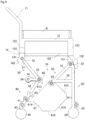
FIG. 1 is a perspective view of a cart according to an embodiment of the present invention viewed from the front; -
FIG. 2 is a perspective view of the cart according to the embodiment of the present invention viewed from the rear; -
FIG. 3 is a rear view of the cart according to the embodiment of the present invention; -
FIG. 4 is a side view of the cart according to the embodiment of the present invention with a basket placed thereon; -
FIG. 5 is a side view of the cart according to the embodiment of the present invention; -
FIG. 6 is a side view illustrating an operating state of the cart according to the embodiment of the present invention; -
FIG. 7 is a side view illustrating an operating state of the cart according to the embodiment of the present invention; -
FIG. 8 is a side view illustrating a storage state of the cart according to the embodiment of the present invention; and -
FIG. 9 is a perspective view illustrating a storage state of the cart according to the embodiment of the present invention viewed from the rear. - A
cart 1 according to the embodiment will be described. Thecart 1 is equipped with a collapsing mechanism that allows the cart to transition from a use state shown inFIG. 1 to FIG. 4 for normal use as a cart during shopping, to a storage state shown inFIG. 8 andFIG. 9 in which the cart is completely collapsed, via an operating state during the collapsing action shown inFIG. 5 to FIG. 7 . First, thecart 1 in the use state will be described with reference toFIG. 1 to FIG. 4 . - The
cart 1 has arack part 10. Therack part 10 includes ahandle 11 and arack part body 12. Therack part body 12 is a frame member and includes a rectangularupper frame 121 open at the top, abottom part 122, and a plurality ofposts 123 connecting theupper frame 121 and thebottom part 122. A load or a shopping basket B can be placed on therack part body 12 through anopening 124 formed by theupper frame 121, as shown inFIG. 4 . - The
handle 11 extends upward from a terminal end edge of theupper frame 121 of therack part body 12. Thehandle 11 is for an operator to maneuver thecart 1. End portions forming thebottom part 122 of therack part body 12 include afront end portion 13 that is positioned on the front side. Thefront end portion 13 is formed withfront extension parts 131 extending downward on both ends in the width direction. Two of theposts 123 of therack part body 12 in the rear of therack part 10 are each bifurcated in the width direction. The respectiveouter portions 125 of the bifurcated ends constitute both ends in the width direction of arear end portion 14 of therack part 10. Theinner portions 126 of the bifurcated ends constitute thebottom part 122 of therack part 10. Arear extension part 141 extends downward from each of theouter portions 125. Therear extension parts 141 are positioned more outside than thefront extension parts 131. Thebottom part 122 has a smaller width than theupper frame 121. Aspace 127 is formed between thebottom part 122 and theupper frame 121. - The
cart 1 has a pair offront leg parts 20. Eachfront leg part 20 includes a bar-likefront leg body 21. One ends 22 of thefront leg bodies 21 are rotatably connected to the outer side of the respectivefront extension parts 131 of thefront end portion 13. Awheel 24 is provided to theother end 23 of thefront leg body 21. Above thewheel 24 of eachfront leg body 21 is a portion that extends forward, with afront leg opening 25 formed therein. Although not shown, a bar can be inserted into eachfront leg opening 25 to restrict torsion of thefront leg part 20. Thefront extension parts 131 each include afront restriction part 132 that extends further forward. Thesefront restriction parts 132 restrict forward rotation of thefront leg parts 20. - The
cart 1 has a pair of upperrear leg parts 30. Each upperrear leg part 30 includes a bar-like upperrear leg body 31. One ends 32 of the upperrear leg bodies 31 are rotatably connected to the inner side of the respectiverear extension parts 141 of therear end portion 14. Therear extension parts 141 each include arear restriction part 142 that extends further diagonally downward and forward. Theserear restriction parts 142 restrict rearward (outward) rotation of the upperrear leg parts 30. The other ends 33 of the upperrear leg bodies 31 are connected to one ends 42 of lowerrear leg parts 40 to be described later such that both ends are rotatable relative to each other. Furthermore, upper fixingparts 34 that extend horizontally in the use state are provided at the other ends 33 of the upperrear leg bodies 31. Theupper fixing parts 34 are each formed with an upper fixing opening 341 in their open ends. - The
cart 1 has a pair of lowerrear leg parts 40. Each lowerrear leg part 40 includes a bar-like lowerrear leg body 41. One ends 42 of the lowerrear leg bodies 41 are connected to the other ends 33 of the upperrear leg parts 30 such that both ends are rotatable relative to each other. Awheel 45 is provided to theother end 43 of each lowerrear leg body 41. Above thewheel 45 of each lowerrear leg body 41 is formed arear leg opening 46. Although not shown, a bar can be inserted into eachrear leg opening 46 to restrict torsion of the upperrear leg part 30 and lowerrear leg part 40. - Furthermore, lower fixing
parts 44 that extend horizontally in the use state are provided at one ends 42 of the lowerrear leg bodies 41. Thelower fixing parts 44 are each formed with alower fixing opening 441 in their open ends. An insertion member may be inserted into theupper fixing opening 341 and thelower fixing opening 441 to secure the upper fixingpart 34 and the lower fixingpart 44. For example, the upper fixingpart 34 and the lower fixingpart 44 are fixedly joined together when the insertion member is inserted into these openings using a ball plunger, for example. The upper fixingpart 34 and the lower fixingpart 44 can be configured to be unlocked by retracting the ball plunger or the like. - The
cart 1 includes aconnection part 70, which is composed of anupper connection part 50 that extends from thefront leg parts 20, and alower connection part 60 that is connected to thisupper connection part 50 and the lowerrear leg parts 40. Theupper connection part 50 includesfirst connection parts 51 andsecond connection parts 52. Thefirst connection parts 51 extend from one ends 22 of thefront leg parts 20, and are rotatably connected to the outer side ofside walls 61 of thelower connection part 60. Thesecond connection parts 52 are provided between thejoints 53 between thefirst connection parts 51 and theside walls 61, and thefront leg bodies 21. - The
lower connection part 60 includes theside walls 61, which are polygonal plates as viewed from the side, and abottom wall 62 between theside walls 61. Theside walls 61 each include, as shown inFIG. 4 , afirst side 611 that is the frontmost side in the use state, asecond side 612 extending upward from thefirst side 611, and athird side 613 extending rearward and downward from thesecond side 612. Alower extension part 63 extends from thethird side 613 horizontally in the use state. Theside wall 61 includes afourth side 614 extending downward from thebottom wall 62, afifth side 615 extending forward from thefourth side 614 to be horizontal in the use state, and asixth side 616 extending upward from thefifth side 615. Thesixth side 616 is connected to thefirst side 611. - The
bottom wall 62 is provided between the fifth sides 615. Thebottom wall 62 is held horizontally in the use state. In the use state, thelower connection part 60 can be used as a load rest, i.e., a load such as a bag can be placed on thebottom wall 62. Thelower extension parts 63 are each rotatably connected to the lowerrear leg parts 40 at the distal ends on the outer side. - As shown in
FIG. 3 , thefront leg parts 20 and the lowerrear leg parts 40 are aligned along the same planes in the width direction of thecart 1. The upperrear leg parts 30 are arranged more outside than thefront leg parts 20 and the lowerrear leg parts 40 in the width direction of thecart 1. Thelower connection part 60 is arranged more inside than thefront leg parts 20 and the lowerrear leg parts 40 in the width direction of thecart 1. Therear extension parts 141 are positioned higher than thefront extension parts 131. The one ends 32 of the upperrear leg parts 30 are positioned higher than the one ends 22 of thefront leg parts 20. - In the
cart 1 according to this embodiment, thefront leg part 20, upperrear leg part 30, lowerrear leg part 40,connection part 70, and rackpart 10 together configure a link mechanism, as shown inFIG. 4 in a side view. The link mechanism is configured as a 5-joint link mechanism, including oneend 22 of thefront leg part 20 as a joint, thefirst connection part 51, the joint 53 of theupper connection part 50 as a joint, theside wall 61, the distal end of thelower extension part 63 as a joint, the lowerrear leg body 41, theother end 33 of the upperrear leg part 30 as a joint, the upperrear leg body 31, oneend 32 of the upperrear leg part 30 as a joint, and therack part body 12. - In this link mechanism, the forward rotation of the
front leg parts 20 is restricted by thefront restriction parts 132 in the use state. Thefront leg parts 20 do not open further outward in the use state, so that thefirst connection parts 51 that rotate with thefront leg parts 20 are also restricted from rotating forward. Likewise, rearward rotation of the upperrear leg parts 30 is restricted by therear restriction parts 142. In the use state, the upper fixingparts 34 andlower fixing parts 44 are secured, and the one ends 42 of the lowerrear leg bodies 41 serving as joints are also fixed in position. Therefore, neither the lowerrear leg bodies 41 nor the upperrear leg bodies 31 rotate. Thus the link mechanism does not work in the use state of thecart 1 according to this embodiment and thebottom part 122 can always stay horizontal. Thiscart 1, when used during shopping in a store, for example, allows use of therack part 10 to put a load thereon, so that a heavy load need not be carried around, whether inside or outside the store. - As will be seen from the following description of the operating state and storage state, the link mechanism described above works as a link mechanism in the operating state, whereby the
front leg parts 20, upperrear leg parts 30, and lowerrear leg parts 40 are folded and stored below the upper surface of therack part 10. - The operating state will be described with reference to
FIG. 5 to FIG. 7 . - For transition from the use state shown in
FIG. 5 to the operating state, first, the upper fixingparts 34 and thelower fixing parts 44 are unlocked. After that, thefront leg parts 20 are pressed, as shown inFIG. 6 . Thefront leg parts 20 can be pressed by bringing thefront leg parts 20 into contact with an edge of a cargo rack C of a bicycle, for example, and by pushing thecart 1 forward. Pressing thefront leg parts 20 causes thefront leg parts 20 to rotate about the one ends 22 as pivots toward thebottom part 122 of therack part 10. This rotation also causes theupper connection part 50 to rotate about the one ends 22 of thefront leg bodies 21 as pivots toward thebottom part 122 of therack part 10. As theupper connection part 50 rotates, thelower connection part 60 moves, too, upward. Pushing thecart 1 further forward causes thesixth side 616 and the bottom wall 62 (fifth side 615) of thelower connection part 60 to each slide on the cargo rack C of the bicycle. Thus thecart 1 can be placed onto the cargo rack C of the bicycle with a small force. - Pushing the
cart 1 further forward causes thefront leg parts 20 to rotate further, and thelower connection part 60 to move upward, as shown inFIG. 7 . This movement of thelower connection part 60 causes the lowerrear leg parts 40 to move upward. The upward movement of the lowerrear leg parts 40 causes the upperrear leg parts 30 to rotate about the one ends 32 upward. Thus the upperrear leg parts 30 begin to overlap the lowerrear leg parts 40 as viewed from the side. - As shown in
FIG. 8 andFIG. 9 , when thefront leg parts 20 have been rotated to be horizontal to the floor surface, the upperrear leg parts 30 and lowerrear leg parts 40 overlap one another in a side view. Thefront leg parts 20 stop the rotation when theirwheels 24 come to contact with the lowerrear leg parts 40. Thus thefront leg parts 20 are stored below the upper surface (indicated with dot lines inFIG. 8 ) formed by theupper frame 121 of therack part 10. The upperrear leg parts 30 and lowerrear leg parts 40 overlap each other in the width direction and are stored below the upper surface formed by theupper frame 121 of therack part 10. Thecart 1 according to this embodiment is compactly collapsible in this way, without thefront leg parts 20, or the upperrear leg parts 30 and lowerrear leg parts 40, sticking out from the upper surface of therack part 10. The upperrear leg bodies 31, lowerrear leg bodies 41, andfront leg bodies 21 are stored below the lower surface formed by thebottom part 122. Theupper connection part 50 andlower connection part 60 are stored in thespace 127 between thebottom part 122 and theupper frame 121 of therack part 10. Thebottom wall 62 of thelower connection part 60 becomes horizontal in the storage state. - The
cart 1 according to this embodiment allows for easy folding of the cart legs in this way without any complex mechanical structure such as an actuator, only by a link mechanism that works in one action, i.e., by pushing thefront leg parts 20 toward thebottom part 122 of the rack part 10 (rearward and upward). The pushing can be achieved while sliding thecart 1 onto the cargo rack C of a bicycle or the like, and there is no need to collapse the cart before placing it onto the rack. Therefore, even when therack part 10 is full of load during use, thecart 1 allows the load to be loaded onto the bicycle or the like without manual transfer of a heavy load. - The
front leg parts 20 and the lowerrear leg parts 40 are aligned along the same planes in the width direction. However, thefront leg parts 20 are positioned below the folded lowerrear leg parts 40 so that they do not interfere with each other. The upperrear leg parts 30 are arranged more outside than thefront leg parts 20 and the lowerrear leg parts 40 in the width direction so that they do not interfere with each other. Thelower connection part 60 is arranged more inside than thefront leg parts 20 and the lowerrear leg parts 40 in the width direction so that they do not interfere with each other. Thus the legs can be folded smoothly. - In the storage state, the folded
front leg parts 20 and thefifth side 615 of thelower connection part 60 are horizontal to the cargo rack, thefifth side 615 of thelower connection part 60 being positioned lower than thefront leg parts 20. With a cargo rack C in the shape of a box, for example, thefront leg parts 20 may be arranged on cargo rack wall surfaces, and thefifth side 615 of thelower connection part 60 may be placed on the bottom surface of the cargo rack C. Thefront leg parts 20 and thelower connection part 60 thus allow stable placement on the cargo rack C, enabling therack part 10 to stay horizontal in the storage state, so that a load can be held more stably. In the storage state, there is a gap formed between thefront leg parts 20 and thefront restriction parts 132. By inserting a wall in this gap, thecart 1 in the storage state can be stably fixed to the cargo rack. - The
cart 1 can readily be returned from the storage state to the use state by gripping thehandle 11 and sliding the cart backward down from the cargo rack C. - While a cart according to the present invention has been described above, the cart according to the present invention is not limited to the embodiment described above. The
connection part 70 may have any configuration as long as it is connected so as to cause the lowerrear leg parts 40 to move in coordination with the rotation of thefront leg parts 20. For example, a link structure can be made by providing slots in the lowerrear leg parts 40, inserting one ends of theconnection part 70 in the slots, and connecting the other ends to one ends of thefront leg parts 20. While thelower connection part 60 of theconnection part 70 in this embodiment is configured to allow a load to be placed thereon in the use state, the configuration is not limited to this and the bottom wall may be omitted. - The structure for fixedly locking and unlocking the upper fixing
parts 34 and thelower fixing parts 44 is not limited to the one in this embodiment. As long as the upperrear leg parts 30 and lowerrear leg parts 40 do not rotate in the use state and are allowed to rotate in the operating state, any structure can be used. - The
cart 1 illustrated in the embodiment above can be used as a shopping cart, for example, which is preferable because the cart allows stable attachment to and detachment from a car trunk or a cargo rack of a tricycle. Thecart 1 also allows itself to be placed on a shelf during storage, which is preferable, as the cart in this case can be used as a basket.
Claims (9)
- A cart (1) comprising:a rack part (10)where a load is placed; anda pair of front leg parts(20) and a pair of rear leg parts provided to the rack part and having wheels (24,45) on distal ends thereof,the cart (1) being able to transition from a use state for use as a cart, through coordinated folding of the pair of front leg parts(20) and the pair of rear leg parts, to a storage state in which the front and rear leg parts are stored below an upper surface of the rack part.
- The cart (1) according to claim 1, whereineach of the pair of front leg parts (20) is connected under a front end portion of the rack part (10) so as to be rotatable from a use position in the use state to a stored position in the storage state,each of the pair of rear leg parts comprises an upper rear leg part (30) and a lower rear leg part (40),the upper rear leg part (30) has one end connected under a rear end portion of the rack part (10) so as to be rotatable from the use position to the stored position, and another end, to which the lower rear leg part (40) is connected so as to be rotatable from the use position to the stored position,a connection part is provided for connection between the front leg part and the lower rear leg part so as to cause the lower rear leg part to move in coordination with rotation of the front leg part.
- The cart according to claim 2, wherein the other end of the upper rear leg part(30) and one end of the lower rear leg part (40) are connected to be restricted from rotation in the use state and allowed to rotate during transition to the storage state.
- The cart according to claim 2, wherein a front restriction part (132) is provided under a front end portion of the rack part so as to restrict forward and upward rotation of the front leg part.
- The cart according to claim 2, wherein a rear restriction part (142) is provided under a rear end portion of the rack part so as to restrict rearward and downward rotation of the rear leg part.
- The cart according to claim 2, wherein each of the other end of the upper rear leg part (30) and one end of the lower rear leg part (40) includes an extension part extending in a horizontal direction in the use state, an opening provided in each of the extension parts, and an insertion member inserted into each of the openings,
the other end of the upper rear leg part and the one end of the lower rear leg part are restricted from rotation in the use state by the insertion member inserted across each pair of the openings, and allowed to rotate during transition to the storage state. - The cart according to claim 2, wherein the connection part comprises an upper connection part (50) having one end rotatably connected to the front leg part, and a lower connection part (60) having one end rotatably connected to another end of the upper connection part (50), another end of the lower connection part (60) is rotatably connected to the lower rear leg parts(40).
- The cart according to claim 7, wherein the lower connection part comprises a pair of side walls (61) and a bottom wall (62) provided between the side walls (61), and
the bottom wall (62) is oriented horizontally in the state of use. - The cart according to claim 2, wherein the front leg part(20) is configured to rotate rearward and upward toward a bottom surface of the rack part(10).
Applications Claiming Priority (1)
| Application Number | Priority Date | Filing Date | Title |
|---|---|---|---|
| JP2023066557A JP2024152393A (en) | 2023-04-14 | 2023-04-14 | cart |
Publications (2)
| Publication Number | Publication Date |
|---|---|
| EP4450368A1 true EP4450368A1 (en) | 2024-10-23 |
| EP4450368B1 EP4450368B1 (en) | 2026-05-06 |
Family
ID=90544711
Family Applications (1)
| Application Number | Title | Priority Date | Filing Date |
|---|---|---|---|
| EP24167323.5A Active EP4450368B1 (en) | 2023-04-14 | 2024-03-28 | Cart |
Country Status (4)
| Country | Link |
|---|---|
| EP (1) | EP4450368B1 (en) |
| JP (1) | JP2024152393A (en) |
| CN (1) | CN118790331A (en) |
| TW (1) | TW202442507A (en) |
Citations (3)
| Publication number | Priority date | Publication date | Assignee | Title |
|---|---|---|---|---|
| FR2775645B1 (en) * | 1998-03-06 | 2000-06-02 | Patrice Vasseur | MECHANISM FOR AUTOMATIC FOLDABLE TROLLEY |
| US20150097358A1 (en) * | 2013-10-07 | 2015-04-09 | Hyundai Motor Company | Electric cart apparatus |
| US20200223465A1 (en) * | 2015-09-01 | 2020-07-16 | Yuval Geffen | Collapsible locomotion platform and cart |
-
2023
- 2023-04-14 JP JP2023066557A patent/JP2024152393A/en active Pending
-
2024
- 2024-03-06 CN CN202410254368.4A patent/CN118790331A/en active Pending
- 2024-03-11 TW TW113108812A patent/TW202442507A/en unknown
- 2024-03-28 EP EP24167323.5A patent/EP4450368B1/en active Active
Patent Citations (3)
| Publication number | Priority date | Publication date | Assignee | Title |
|---|---|---|---|---|
| FR2775645B1 (en) * | 1998-03-06 | 2000-06-02 | Patrice Vasseur | MECHANISM FOR AUTOMATIC FOLDABLE TROLLEY |
| US20150097358A1 (en) * | 2013-10-07 | 2015-04-09 | Hyundai Motor Company | Electric cart apparatus |
| US20200223465A1 (en) * | 2015-09-01 | 2020-07-16 | Yuval Geffen | Collapsible locomotion platform and cart |
Also Published As
| Publication number | Publication date |
|---|---|
| JP2024152393A (en) | 2024-10-25 |
| TW202442507A (en) | 2024-11-01 |
| CN118790331A (en) | 2024-10-18 |
| EP4450368B1 (en) | 2026-05-06 |
Similar Documents
| Publication | Publication Date | Title |
|---|---|---|
| EP3322629B1 (en) | Foldable wagon | |
| CN107914742B (en) | Folding vehicle | |
| JP3234584U (en) | Folding stroller | |
| US10272937B2 (en) | Expanding wheel frame wagon | |
| US4763911A (en) | Foldable baby carriage | |
| US8979098B2 (en) | Collapsible platform truck | |
| EP1967440A2 (en) | Foldable stroller | |
| CN111376958B (en) | Folding pull-rod vehicle | |
| EP1967439A2 (en) | Foldable stroller | |
| CN110281991B (en) | Barrows with wheels | |
| WO2017037702A1 (en) | Collapsible locomotion platform and cart | |
| US10322738B1 (en) | Collapsible structure for interlinking front and rear wheels of golf cart | |
| US6976697B2 (en) | Passenger carrier frame | |
| EP4450368B1 (en) | Cart | |
| JP6289994B2 (en) | Electric cart device | |
| CN221293586U (en) | Transfer car (buggy) and outdoor transfer device | |
| CN118182110A (en) | Vehicle battery loading and unloading device | |
| US3804431A (en) | Convertible shopping cart | |
| CN214138584U (en) | trolley | |
| CN1817713B (en) | Small folding single-wheel handcart with connection and traction conversion, handcart device and shipping and displaying method | |
| CN120663991A (en) | Folding trolley with loading plate and casters folding | |
| JP3395578B2 (en) | Goods storage | |
| CN104527762A (en) | Foldable frame of baby stroller | |
| HK1245202B (en) | Foldable wagon |
Legal Events
| Date | Code | Title | Description |
|---|---|---|---|
| PUAI | Public reference made under article 153(3) epc to a published international application that has entered the european phase |
Free format text: ORIGINAL CODE: 0009012 |
|
| STAA | Information on the status of an ep patent application or granted ep patent |
Free format text: STATUS: THE APPLICATION HAS BEEN PUBLISHED |
|
| AK | Designated contracting states |
Kind code of ref document: A1 Designated state(s): AL AT BE BG CH CY CZ DE DK EE ES FI FR GB GR HR HU IE IS IT LI LT LU LV MC ME MK MT NL NO PL PT RO RS SE SI SK SM TR |
|
| STAA | Information on the status of an ep patent application or granted ep patent |
Free format text: STATUS: REQUEST FOR EXAMINATION WAS MADE |
|
| 17P | Request for examination filed |
Effective date: 20250312 |
|
| GRAP | Despatch of communication of intention to grant a patent |
Free format text: ORIGINAL CODE: EPIDOSNIGR1 |
|
| STAA | Information on the status of an ep patent application or granted ep patent |
Free format text: STATUS: GRANT OF PATENT IS INTENDED |
|
| INTG | Intention to grant announced |
Effective date: 20251127 |
|
| GRAS | Grant fee paid |
Free format text: ORIGINAL CODE: EPIDOSNIGR3 |
|
| GRAA | (expected) grant |
Free format text: ORIGINAL CODE: 0009210 |
|
| STAA | Information on the status of an ep patent application or granted ep patent |
Free format text: STATUS: THE PATENT HAS BEEN GRANTED |
|
| AK | Designated contracting states |
Kind code of ref document: B1 Designated state(s): AL AT BE BG CH CY CZ DE DK EE ES FI FR GB GR HR HU IE IS IT LI LT LU LV MC ME MK MT NL NO PL PT RO RS SE SI SK SM TR |
|
| REG | Reference to a national code |
Ref country code: CH Ref legal event code: F10 Free format text: ST27 STATUS EVENT CODE: U-0-0-F10-F00 (AS PROVIDED BY THE NATIONAL OFFICE) Effective date: 20260506 Ref country code: GB Ref legal event code: FG4D |