EP4450337A1 - Safety belt outlet arrangement - Google Patents
Safety belt outlet arrangement Download PDFInfo
- Publication number
- EP4450337A1 EP4450337A1 EP23169192.4A EP23169192A EP4450337A1 EP 4450337 A1 EP4450337 A1 EP 4450337A1 EP 23169192 A EP23169192 A EP 23169192A EP 4450337 A1 EP4450337 A1 EP 4450337A1
- Authority
- EP
- European Patent Office
- Prior art keywords
- belt
- outlet
- bezel
- elastic region
- vehicle
- Prior art date
- Legal status (The legal status is an assumption and is not a legal conclusion. Google has not performed a legal analysis and makes no representation as to the accuracy of the status listed.)
- Granted
Links
Images


Classifications
-
- B—PERFORMING OPERATIONS; TRANSPORTING
- B60—VEHICLES IN GENERAL
- B60R—VEHICLES, VEHICLE FITTINGS, OR VEHICLE PARTS, NOT OTHERWISE PROVIDED FOR
- B60R22/00—Safety belts or body harnesses in vehicles
-
- B—PERFORMING OPERATIONS; TRANSPORTING
- B60—VEHICLES IN GENERAL
- B60R—VEHICLES, VEHICLE FITTINGS, OR VEHICLE PARTS, NOT OTHERWISE PROVIDED FOR
- B60R22/00—Safety belts or body harnesses in vehicles
- B60R22/18—Anchoring devices
- B60R22/24—Anchoring devices secured to the side, door, or roof of the vehicle
-
- B—PERFORMING OPERATIONS; TRANSPORTING
- B60—VEHICLES IN GENERAL
- B60R—VEHICLES, VEHICLE FITTINGS, OR VEHICLE PARTS, NOT OTHERWISE PROVIDED FOR
- B60R13/00—Elements for body-finishing, identifying, or decorating; Arrangements or adaptations for advertising purposes
- B60R13/02—Internal Trim mouldings ; Internal Ledges; Wall liners for passenger compartments; Roof liners
-
- B—PERFORMING OPERATIONS; TRANSPORTING
- B60—VEHICLES IN GENERAL
- B60R—VEHICLES, VEHICLE FITTINGS, OR VEHICLE PARTS, NOT OTHERWISE PROVIDED FOR
- B60R13/00—Elements for body-finishing, identifying, or decorating; Arrangements or adaptations for advertising purposes
- B60R13/02—Internal Trim mouldings ; Internal Ledges; Wall liners for passenger compartments; Roof liners
- B60R13/0237—Side or rear panels
- B60R13/025—Pillars; Roof rails
-
- B—PERFORMING OPERATIONS; TRANSPORTING
- B60—VEHICLES IN GENERAL
- B60R—VEHICLES, VEHICLE FITTINGS, OR VEHICLE PARTS, NOT OTHERWISE PROVIDED FOR
- B60R22/00—Safety belts or body harnesses in vehicles
- B60R22/18—Anchoring devices
- B60R2022/1818—Belt guides
Definitions
- the present application relates to a belt outlet arrangement.
- the application further relates to a belt outlet system, a vehicle, and a method.
- Belt outlets are common provided in the interior of motor vehicles. They serve as openings, or ducts, which enable that a belt, typically a safety belt, extends movably between a compartment behind an interior trim of the vehicle structure, where the belt is firmly connected to the vehicle body, and an interior of the vehicle, normally a passenger space, where the belt may be pulled through the belt outlet to a desired length for use by a driver or passenger of the vehicle.
- a belt typically a safety belt
- a belt outlet typically serves various purposes. While the belt needs to be easily movable through the belt outlet, the belt outlet also defines one of the positions from which the belt mechanically interacts with a user. Thus, the belt outlet functions as a mechanical guide for the belt motion, which ideally has low friction, is mechanically robust and is located at an ergonomically suited position in the vehicle. Furthermore, as trims provide for noise reduction in the vehicle interior as well as visual concealment of the vehicle structure, an aperture in the trim through which the belt extends means a rupture in the acoustic and visual sealing provided by the trim. Therefore, it is typically intended that a belt outlet provide an opening for the belt that is as small as possible. However, installation of the belt during manufacture of the vehicle normally demands that relatively large belt components, such as a belt lock, can be pushed through the trim at a position of the belt outlet.
- a belt outlet arrangement in particular for use in a vehicle, is described.
- the belt outlet arrangement comprises an outlet bezel configured to guide a motion of a belt which extends movably through a bezel opening of the outlet bezel, and a trim portion adapted to cover at least a region of a structure of a vehicle to which the belt is connected, the trim portion comprising an elastic region in which a trim opening is arranged.
- the outlet bezel is arranged adjacent the elastic region of the trim portion such that the trim opening is cladded at least partially by means of the outlet bezel to form an outlet for the belt through the trim portion.
- the trim portion can be an interior trim, i.e., a portion of an interior trim, in particular an upper pillar trim, such as a rear upper pillar trim.
- the elastic region facilitates that belt components, in particular a belt lock, be pushed through the trim opening during installation of the belt.
- the elastic region facilitates that a size of the trim opening can be elastically expanded, especially before an installation of the outlet bezel.
- the trim opening can be dimensioned such that it is smaller during a relaxed state of the elastic region than an opening size required for pushing the belt components through.
- the trim opening can be smaller during a relaxed state of the elastic region than a cross section of the belt components to be pushed through the trim opening.
- the bezel also can be dimensioned smaller than a size of an opening required for pushing the belt components through, in particular smaller than the cross section of the belt components.
- the trim opening and the bezel can be dimensioned essentially in accordance with a minimum size required for the belt outlet after installation, such as for providing a mechanical guide for the belt motion. In this way, a visual impact caused by the belt outlet arrangement, in particular by the outlet bezel, can be minimized.
- the outlet bezel may comprise rigid material.
- the rigid material may be rigid plastic.
- the outlet bezel may be configured to provide a rigid guide for the motion of the belt.
- the elastic region of the trim portion may comprise silicone.
- the elastic region may enable changing a position of the outlet bezel relative to at least a part of the trim portion, in particular relative to trim parts surrounding the elastic region.
- an adjustable position of the outlet bezel can be provided for, such as by means of an adjustable vehicle structure supporting the outlet bezel and/or an actuator device, without requiring an enlarged opening in the trim portion.
- an acoustic and visual impact caused by the belt outlet arrangement in connection with a changeable position of the outlet bezel can be further reduced.
- the elastic region may enable changing the position of the outlet bezel parallel to a surface of the trim portion.
- the surface of the trim portion may be a surface facing towards an interior, or a passenger space, of the vehicle.
- the elastic region may enable changing the position of the outlet bezel in an extension plane of the elastic region.
- the elastic region may enable changing the position of the outlet bezel in a direction non-parallel to an extension plane of the elastic region, in particular in a direction vertical to an extension plane of the trim portion adjacent the elastic region.
- the structure of the vehicle may comprise a pillar of the vehicle.
- the elastic region may enable changing the position of the outlet bezel in at least one of a vertical and a longitudinal direction of the vehicle and/or of the pillar.
- a "longitudinal direction" of the vehicle and/or of the pillar may be defined as a direction of the vehicle and/or of the pillar which is parallel to a main driving direction of the vehicle.
- a "vertical direction" of the vehicle and/or of the pillar may be orthogonal to the main driving direction of the vehicle.
- changing the position of the outlet bezel in the longitudinal direction of the vehicle and/or of the pillar may comprise changing of the position of the outlet bezel such that at least a geometric component of a motion of the outlet bezel from the position prior to the changing towards the position after the changing is parallel to the longitudinal direction of the vehicle and/or of the pillar.
- changing the position of the outlet bezel in the vertical direction of the vehicle and/or of the pillar may comprise changing of the position of the outlet bezel such that at least a geometric component of a motion of the outlet bezel from the position prior to the changing towards the position after the changing is parallel to the vertical direction of the vehicle and/or of the pillar.
- the elastic region may enable changing the position of the outlet bezel in a lateral direction of the vehicle and/or of the pillar.
- a "lateral direction" of the vehicle and/or of the pillar may be defined as a direction of the vehicle and/or of the pillar which is orthogonal to a main driving direction of the vehicle in a horizontal plane of the vehicle.
- Changing the position of the outlet bezel in the lateral direction of the vehicle and/or of the pillar may comprise changing of the position of the outlet bezel such that at least a geometric component of a motion of the outlet bezel from the position prior to the changing towards the position after the changing is parallel to the lateral direction of the vehicle and/or of the pillar.
- a position of the outlet bezel may be changeable over at least a predetermined range.
- An elasticity of a material of the elastic region and/or a size of the elastic region may be chosen such that the elastic region deforms at least essentially wrinkle-free when the position of the outlet bezel is changed within the predetermined range.
- a belt outlet system comprises a belt outlet arrangement as presently described, and at least one actuator device arranged to change the position of the outlet bezel.
- a travel range of the at least one actuator device may correspond to the predetermined range.
- the predetermined range may correspond to a range provided for adjusting the position of the outlet bezel to at least one of a shoulder position, a neck position or a body size of a user of the belt.
- the belt outlet system may further comprise at least one sensor configured to detect a position of at least a part of a body of a user of the belt.
- the at least one sensor may be configured to visually detect a position of a shoulder of the user of the belt.
- the belt outlet system may further comprise a control unit.
- the control unit may be configured to receive, from the at least one sensor, a sensor signal indicative of the position of at least the part of the body of the user of the belt, generate, based on the received sensor signal, a control signal for operating the at least one actuator device to adjust a position of the outlet bezel in accordance with the position of at least the part of the body of the user of the belt, and output the control signal towards the at least one actuator device.
- a vehicle comprises a belt outlet arrangement as presently described and/or a belt outlet system as presently described.
- the belt outlet system comprises a belt outlet arrangement.
- the belt outlet arrangement has an outlet bezel configured to guide a motion of a belt which extends movably through a bezel opening of the outlet bezel, and a trim portion adapted to cover at least a region of a structure of a vehicle to which the belt is connected, the trim portion comprising an elastic region in which a trim opening is arranged, wherein the outlet bezel is arranged adjacent the elastic region of the trim portion such that the trim opening is cladded at least partially by means of the outlet bezel to form an outlet for the belt through the trim portion, and the elastic region enables changing a position of the outlet bezel relative to at least a part of the trim portion.
- the belt outlet system further comprises at least one actuator device arranged to change the position of the outlet bezel relative to the trim portion, at least one sensor configured to detect a position of at least a part of a body of a user of the belt, and a control unit.
- the method comprises receiving, by means of the control unit and from the at least one sensor, a sensor signal indicative of the position of at least the part of the body of the user of the belt, generating, by means of the control unit and based on the received sensor signal, a control signal for operating the at least one actuator device to adjust a position of the outlet bezel in accordance with the position of at least the part of the body of the user of the belt, and outputting, by means of the control unit, the control signal towards the at least one actuator device.
- Fig. 1A shows schematically and exemplarily a perspective, cross-sectional view of a belt outlet arrangement 100.
- the belt outlet arrangement 100 comprises a trim portion 110, in which a trim opening 112 extends.
- the belt outlet arrangement 100 further comprises an outlet bezel 120 which is arranged in the trim opening 112.
- the trim portion 110 covers at least partially a vehicle structure S.
- the trim opening 112 permits that a belt B, for example, a safety belt, extends movably through the trim portion 110 from a side where the structure S is located to the other side of the trim portion 110, for example, corresponding to an interior or a passenger space of the vehicle.
- the outlet bezel 120 has a bezel opening 122 through which the belt B extends.
- the outlet bezel 120 is arranged such that it clads the trim opening 112 along an inner circumference of the trim opening 112. Moreover, the outlet bezel 120 reduces the size of an effective opening through which the belt B extends, i.e., from the larger size of the trim opening 112 to the smaller size of the bezel opening 122.
- a size of the trim opening 112 may be chosen in accordance with a size required for pushing belt components of the belt B, for example, a belt lock, through the trim portion 110 during installation of the belt B.
- a size of the bezel opening 122 may be chosen in accordance with a minimal size required to provide secure and guided motion of the belt B, with low friction, during use.
- Fig. 1B shows a side view of the belt outlet arrangement 100 as seen from an interior of the vehicle.
- Identical reference signs as in Fig. 1A denote identical features.
- a position of the belt outlet arrangement 100 corresponds in the shown example to an upper section of the rear column of the vehicle.
- a minimum size of the bezel opening 122 as needed for providing a low-friction, guided motion of the belt B is significantly smaller than a size of the trim opening 112 as required for installation of the belt B.
- an impact caused by the profile of the bezel 120 on the visual appearance of the belt outlet arrangement 100 is significant in this case.
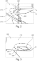
- Fig. 2 shows schematically and exemplarily a perspective, cross-sectional view of a belt outlet arrangement 200 according to another example.
- the belt outlet arrangement 200 comprises a trim portion 210 and an outlet bezel 220.
- the outlet bezel 220 clads a trim opening 212 of the trim portion 210.
- a belt B extends through a bezel opening 222 of the outlet bezel 220.
- the trim portion 210 covers a structure S, such as a rear column of a vehicle.
- the outlet bezel 220 provides for low-friction, guided motion of the belt B through the trim portion 210.
- the trim portion 210 comprises an elastic region 214.
- An outer boundary of the elastic region 214 is indicated in Fig. 2 by the dashed curve segment.
- the elastic region 214 extends around the trim opening 212.
- the outlet bezel 220 which clads the trim opening 212, is arranged adjacent the elastic region 214.
- the elastic region 214 surrounds the outlet bezel 220 in a plane of the trim portion 210.
- the elastic region 214 enables changing a position of the outlet bezel 220, for example, parallel to a direction within an extension plane of the elastic region 214.
- the elastic region 214 comprises elastic material, such as silicone.
- the elastic region 214 enables in some examples moving the outlet bezel 220 relative to parts of the trim portion 210 without causing wrinkles of the elastic region 214.
- the belt outlet arrangement 200 comprises in some examples an outlet bezel 220 which is made of a rigid material, such as rigid plastic. In this way, the belt outlet arrangement 200 facilitates in some examples low-friction motion of the belt B through the belt outlet arrangement 200. Particularly, in some examples, a friction coefficient for a motion of the belt B on the material of the outlet bezel 220 is less than a friction coefficient for a hypothetic motion of the belt B on the material of the elastic region 214.
- Fig. 3 shows a side view of the belt outlet arrangement 200.
- a visual impact caused by the outlet bezel 220 is significantly less than in the case of the outlet bezel 120 in Fig. 1B .
- This is essentially enabled by the elastic region 212.
- the elastic region 214 enables in particular that during installation of the belt B and prior to an installation of the outlet bezel 220 the trim opening 212 can be expanded when belt components are pushed through the trim opening 212.
- a size of the trim opening 212 does not need to be chosen larger than a size required for guiding a motion of the belt B when in use, i.e., after the outlet bezel 220 has been installed.
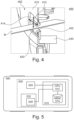
- Fig. 4 shows schematically and exemplarily a perspective, cross-sectional view of a belt outlet system 400.
- the belt outlet system 400 comprises a belt outlet arrangement 402 and an actuator device 430.
- the belt outlet arrangement 402 comprises a trim portion 410 having an elastic region 414 in which a trim opening 412 extends.
- the belt outlet arrangement 402 comprises an outlet bezel 420 which clads the trim opening 412 and which has a bezel opening 422.
- the elastic region 414 facilitates that a position of the outlet bezel 420 is changed vertically as well as horizontally with respect to surrounding parts of the trim portion 410.
- the actuator device 430 acts on the outlet bezel 420.
- the actuator device 430 is attached to, and supported by, a structure of the vehicle.
- at least one actuatable member of the actuator device 430 is connected to the outlet bezel 420.
- a position of the outlet bezel 420 can be changed parallel to at least one direction, for example, of a vertical structure which is covered by the trim portion 410.
- the actuator device 430 acts on both the outlet bezel 420 and the structure of the vehicle to change the position of the outlet bezel 420 relative to the structure of the vehicle.
- Changing the position of the outlet bezel 420 by means of the actuator device 430 is performed in some examples for adjusting a position of the outlet bezel 420 to a body size of the user of the belt B, for example, a passenger or driver of the vehicle in which the belt outlet system 400 is installed.
- the position of the outlet bezel 420 is changeable at least in a vertical direction for adjusting a vertical position of the outlet bezel 420 to a shoulder height, or a neck height, etc., of the user.
- adjusting a position of the outlet bezel 420 comprises changing the position of the outlet bezel 420 at least in a horizontal direction, for example, parallel to the longitudinal direction, i.e., the main driving direction, of the vehicle in which the belt outlet system 400 is installed, for example, in accordance with an adjustable seat position.
- changing the position of the outlet bezel 420 in a vertical direction and/or parallel to the main driving direction of the vehicle is performed such that the position of the outlet bezel 420 is changed in an extension plane of the elastic region 414, as indicated in Fig. 4 by the double arrows.
- the extension plane of the elastic region 414 is oriented at least essentially parallel to the vertical direction and the longitudinal direction of the vehicle.
- the extension plane of the elastic region 414 is oriented at an angle relative to the plane spanned by the vertical direction and the longitudinal direction of the vehicle.
- the elastic region 414 enables changing the position of the outlet bezel 420 in a direction non-parallel to an extension plane of the elastic region 414, and non-parallel to the surface of the trim portion 410 surrounding the elastic region 414.
- adjusting a position of the outlet bezel 420 comprises changing the position of the outlet bezel 420 in a horizontal direction orthogonal to the longitudinal direction, i.e., in a lateral direction, of the vehicle in which the belt outlet system 400 is installed.
- the position of the outlet bezel 420 is adjustable in this way to a lateral body size, such as a detected shoulder width, of the user.
- changing the position of the outlet bezel 420 in the lateral direction involves changing the position of the outlet bezel 420 in a direction non-parallel to an extension plane of the elastic region 414, and non-parallel to the surface of the trim portion 410 surrounding the elastic region 414.
- Fig. 5 shows schematically and exemplarily a vehicle 500 comprising a belt outlet system 505.
- the belt outlet system 505 comprises a belt outlet arrangement 532 having an actuator device 530, which is arranged to change the position of an outlet bezel of the belt outlet arrangement 532.
- the belt outlet system 505 further comprises a sensor 520.
- the sensor 520 is arranged to detect the position of at least a body part of a user of the belt associated with the belt outlet arrangement 532.
- the sensor 520 comprises a camera which is operated for detecting a shoulder position and/or a neck position of the user.
- the belt outlet system 505 further comprises a control unit 510.
- the control unit 510 comprises a processing unit 512, which is operably connected to a data storage unit 514 of the control unit 510.
- the control unit 510 is communicatively connected to the sensor 520 and the actuator device 530.
- the data storage unit 514 contains program code which is executable by means of the processing unit 512.
- the processing unit 512 is configured to receive from the sensor 520 sensor signal indicating the position of at least a body part of the user of the belt outlet arrangement 532.
- the processing unit 512 is configured to determine, based on the received sensor signal, a control signal for controlling the actuator device 530 in accordance with a determined position of at least the body part of the user.
- the control unit 512 is further configured to generate and output the determined control signal towards the actuator device 530.
- the actuator device 530 operates to change the position of the outlet bezel accordingly.
- the control unit 512 is in some examples configured to perform image analysis on a video signal received from the sensor 520 for determining the position of the body part of the user in the image.
- the control unit 512 is in some examples configured to perform image analysis on a video signal received from the sensor 520 for determining the position of the body part of the user in the image.
- other types of sensors 520 and/or other types of data processing applied to a sensor signal by means of the control unit 512 are used for determining the position of at least a body part of the user.
- Fig. 6 shows a flow diagram of a method 600 for operating a belt outlet system.
- the method 600 is executable, for example, using the belt outlet system 505.
- the method 600 comprises receiving, by means of a control unit and from at least one sensor of the belt outlet system, a sensor signal indicative of the position of at least a part of the body of a user of the belt which is associated with a belt outlet arrangement of the belt outlet system, step 610.
- the method 600 further comprises generating, by means of the control unit and based on the received sensor signal, a control signal for operating at least one actuator device of the belt outlet system to adjust a position of the outlet bezel in accordance with the position of at least the part of the body of the user, step 620.
- the method 600 comprises outputting, by means of the control unit, the control signal towards the at least one actuator device of the belt outlet system.
Landscapes
- Engineering & Computer Science (AREA)
- Mechanical Engineering (AREA)
- Automotive Seat Belt Assembly (AREA)
- Fittings On The Vehicle Exterior For Carrying Loads, And Devices For Holding Or Mounting Articles (AREA)
Abstract
Description
- The present application relates to a belt outlet arrangement. The application further relates to a belt outlet system, a vehicle, and a method.
- Belt outlets are common provided in the interior of motor vehicles. They serve as openings, or ducts, which enable that a belt, typically a safety belt, extends movably between a compartment behind an interior trim of the vehicle structure, where the belt is firmly connected to the vehicle body, and an interior of the vehicle, normally a passenger space, where the belt may be pulled through the belt outlet to a desired length for use by a driver or passenger of the vehicle.
- Apart from providing a conduit for the belt through the trim, a belt outlet typically serves various purposes. While the belt needs to be easily movable through the belt outlet, the belt outlet also defines one of the positions from which the belt mechanically interacts with a user. Thus, the belt outlet functions as a mechanical guide for the belt motion, which ideally has low friction, is mechanically robust and is located at an ergonomically suited position in the vehicle. Furthermore, as trims provide for noise reduction in the vehicle interior as well as visual concealment of the vehicle structure, an aperture in the trim through which the belt extends means a rupture in the acoustic and visual sealing provided by the trim. Therefore, it is typically intended that a belt outlet provide an opening for the belt that is as small as possible. However, installation of the belt during manufacture of the vehicle normally demands that relatively large belt components, such as a belt lock, can be pushed through the trim at a position of the belt outlet.
- To comply with these requirements, conventionally, a relatively large opening is provided in the trim, which after installation of the belt becomes partially closed by means of a bezel.
- There is an ongoing need for improved belt outlet techniques.
- Accordingly, there is provided a belt outlet arrangement according to
claim 1, a belt outlet system according to claim 9, a vehicle according to claim 14, and a method according to claim 15. - According to a first aspect, a belt outlet arrangement, in particular for use in a vehicle, is described. The belt outlet arrangement comprises an outlet bezel configured to guide a motion of a belt which extends movably through a bezel opening of the outlet bezel, and a trim portion adapted to cover at least a region of a structure of a vehicle to which the belt is connected, the trim portion comprising an elastic region in which a trim opening is arranged. The outlet bezel is arranged adjacent the elastic region of the trim portion such that the trim opening is cladded at least partially by means of the outlet bezel to form an outlet for the belt through the trim portion. The trim portion can be an interior trim, i.e., a portion of an interior trim, in particular an upper pillar trim, such as a rear upper pillar trim.
- The elastic region facilitates that belt components, in particular a belt lock, be pushed through the trim opening during installation of the belt. In this context, the elastic region facilitates that a size of the trim opening can be elastically expanded, especially before an installation of the outlet bezel. As a result, the trim opening can be dimensioned such that it is smaller during a relaxed state of the elastic region than an opening size required for pushing the belt components through. In particular, the trim opening can be smaller during a relaxed state of the elastic region than a cross section of the belt components to be pushed through the trim opening.
- This facilitates that the bezel also can be dimensioned smaller than a size of an opening required for pushing the belt components through, in particular smaller than the cross section of the belt components. Thus, the trim opening and the bezel can be dimensioned essentially in accordance with a minimum size required for the belt outlet after installation, such as for providing a mechanical guide for the belt motion. In this way, a visual impact caused by the belt outlet arrangement, in particular by the outlet bezel, can be minimized.
- The outlet bezel may comprise rigid material. The rigid material may be rigid plastic. The outlet bezel may be configured to provide a rigid guide for the motion of the belt. The elastic region of the trim portion may comprise silicone.
- The elastic region may enable changing a position of the outlet bezel relative to at least a part of the trim portion, in particular relative to trim parts surrounding the elastic region. In this way, an adjustable position of the outlet bezel can be provided for, such as by means of an adjustable vehicle structure supporting the outlet bezel and/or an actuator device, without requiring an enlarged opening in the trim portion. Thus, an acoustic and visual impact caused by the belt outlet arrangement in connection with a changeable position of the outlet bezel can be further reduced.
- The elastic region may enable changing the position of the outlet bezel parallel to a surface of the trim portion. The surface of the trim portion may be a surface facing towards an interior, or a passenger space, of the vehicle. The elastic region may enable changing the position of the outlet bezel in an extension plane of the elastic region. In addition or as an alternative, the elastic region may enable changing the position of the outlet bezel in a direction non-parallel to an extension plane of the elastic region, in particular in a direction vertical to an extension plane of the trim portion adjacent the elastic region.
- The structure of the vehicle may comprise a pillar of the vehicle. The elastic region may enable changing the position of the outlet bezel in at least one of a vertical and a longitudinal direction of the vehicle and/or of the pillar.
- A "longitudinal direction" of the vehicle and/or of the pillar may be defined as a direction of the vehicle and/or of the pillar which is parallel to a main driving direction of the vehicle. A "vertical direction" of the vehicle and/or of the pillar may be orthogonal to the main driving direction of the vehicle. Furthermore, changing the position of the outlet bezel in the longitudinal direction of the vehicle and/or of the pillar may comprise changing of the position of the outlet bezel such that at least a geometric component of a motion of the outlet bezel from the position prior to the changing towards the position after the changing is parallel to the longitudinal direction of the vehicle and/or of the pillar. Likewise, changing the position of the outlet bezel in the vertical direction of the vehicle and/or of the pillar may comprise changing of the position of the outlet bezel such that at least a geometric component of a motion of the outlet bezel from the position prior to the changing towards the position after the changing is parallel to the vertical direction of the vehicle and/or of the pillar.
- In addition or as an alternative, the elastic region may enable changing the position of the outlet bezel in a lateral direction of the vehicle and/or of the pillar. A "lateral direction" of the vehicle and/or of the pillar may be defined as a direction of the vehicle and/or of the pillar which is orthogonal to a main driving direction of the vehicle in a horizontal plane of the vehicle. Changing the position of the outlet bezel in the lateral direction of the vehicle and/or of the pillar may comprise changing of the position of the outlet bezel such that at least a geometric component of a motion of the outlet bezel from the position prior to the changing towards the position after the changing is parallel to the lateral direction of the vehicle and/or of the pillar.
- A position of the outlet bezel may be changeable over at least a predetermined range. An elasticity of a material of the elastic region and/or a size of the elastic region may be chosen such that the elastic region deforms at least essentially wrinkle-free when the position of the outlet bezel is changed within the predetermined range.
- According to a second aspect, a belt outlet system is described. The belt outlet system comprises a belt outlet arrangement as presently described, and at least one actuator device arranged to change the position of the outlet bezel.
- A travel range of the at least one actuator device may correspond to the predetermined range. The predetermined range may correspond to a range provided for adjusting the position of the outlet bezel to at least one of a shoulder position, a neck position or a body size of a user of the belt.
- The belt outlet system may further comprise at least one sensor configured to detect a position of at least a part of a body of a user of the belt. The at least one sensor may be configured to visually detect a position of a shoulder of the user of the belt.
- The belt outlet system may further comprise a control unit. The control unit may be configured to receive, from the at least one sensor, a sensor signal indicative of the position of at least the part of the body of the user of the belt, generate, based on the received sensor signal, a control signal for operating the at least one actuator device to adjust a position of the outlet bezel in accordance with the position of at least the part of the body of the user of the belt, and output the control signal towards the at least one actuator device.
- In this way, automatic adjustment of the position of the outlet bezel to at least one of a shoulder position, a neck position or a body size of a user of the belt is achievable.
- According to a third aspect, a vehicle is described. The vehicle comprises a belt outlet arrangement as presently described and/or a belt outlet system as presently described.
- According to a fourth aspect, a method of operating a belt outlet system is described. The belt outlet system comprises a belt outlet arrangement. The belt outlet arrangement has an outlet bezel configured to guide a motion of a belt which extends movably through a bezel opening of the outlet bezel, and a trim portion adapted to cover at least a region of a structure of a vehicle to which the belt is connected, the trim portion comprising an elastic region in which a trim opening is arranged, wherein the outlet bezel is arranged adjacent the elastic region of the trim portion such that the trim opening is cladded at least partially by means of the outlet bezel to form an outlet for the belt through the trim portion, and the elastic region enables changing a position of the outlet bezel relative to at least a part of the trim portion. The belt outlet system further comprises at least one actuator device arranged to change the position of the outlet bezel relative to the trim portion, at least one sensor configured to detect a position of at least a part of a body of a user of the belt, and a control unit. The method comprises receiving, by means of the control unit and from the at least one sensor, a sensor signal indicative of the position of at least the part of the body of the user of the belt, generating, by means of the control unit and based on the received sensor signal, a control signal for operating the at least one actuator device to adjust a position of the outlet bezel in accordance with the position of at least the part of the body of the user of the belt, and outputting, by means of the control unit, the control signal towards the at least one actuator device.
- Further details, advantages and objectives of the invention become apparent from the drawings and the detailed description. There is shown in the drawings:
- Figs 1A - 1B
- different views of a belt outlet arrangement;
- Fig. 2
- a perspective, cross-sectional view of a belt outlet arrangement according to an example;
- Fig. 3
- a side view of the belt outlet arrangement of
Fig. 2 ; - Fig. 4
- a perspective, cross-sectional view of a belt outlet system according to an example;
- Fig. 5
- a schematic view of a vehicle according to an example, and
- Fig. 6
- a flow diagram of a method according to an example
-
Fig. 1A shows schematically and exemplarily a perspective, cross-sectional view of abelt outlet arrangement 100. Thebelt outlet arrangement 100 comprises atrim portion 110, in which atrim opening 112 extends. Thebelt outlet arrangement 100 further comprises anoutlet bezel 120 which is arranged in thetrim opening 112. Thetrim portion 110 covers at least partially a vehicle structure S. Moreover, thetrim opening 112 permits that a belt B, for example, a safety belt, extends movably through thetrim portion 110 from a side where the structure S is located to the other side of thetrim portion 110, for example, corresponding to an interior or a passenger space of the vehicle. - The
outlet bezel 120 has abezel opening 122 through which the belt B extends. Theoutlet bezel 120 is arranged such that it clads thetrim opening 112 along an inner circumference of thetrim opening 112. Moreover, theoutlet bezel 120 reduces the size of an effective opening through which the belt B extends, i.e., from the larger size of thetrim opening 112 to the smaller size of thebezel opening 122. - A size of the
trim opening 112 may be chosen in accordance with a size required for pushing belt components of the belt B, for example, a belt lock, through thetrim portion 110 during installation of the belt B. In contrast, a size of thebezel opening 122 may be chosen in accordance with a minimal size required to provide secure and guided motion of the belt B, with low friction, during use. -
Fig. 1B shows a side view of thebelt outlet arrangement 100 as seen from an interior of the vehicle. Identical reference signs as inFig. 1A denote identical features. A position of thebelt outlet arrangement 100 corresponds in the shown example to an upper section of the rear column of the vehicle. - As can be seen in
Fig. 1B , a minimum size of thebezel opening 122 as needed for providing a low-friction, guided motion of the belt B is significantly smaller than a size of thetrim opening 112 as required for installation of the belt B. In consequence, an impact caused by the profile of thebezel 120 on the visual appearance of thebelt outlet arrangement 100 is significant in this case. -
Fig. 2 shows schematically and exemplarily a perspective, cross-sectional view of abelt outlet arrangement 200 according to another example. Thebelt outlet arrangement 200 comprises atrim portion 210 and anoutlet bezel 220. Theoutlet bezel 220 clads atrim opening 212 of thetrim portion 210. Moreover, a belt B extends through abezel opening 222 of theoutlet bezel 220. Thetrim portion 210 covers a structure S, such as a rear column of a vehicle. In addition, theoutlet bezel 220 provides for low-friction, guided motion of the belt B through thetrim portion 210. - Regarding the aforesaid features, the description of the
belt outlet arrangement 100 inFigs 1A and 1B applies correspondingly unless otherwise clear from the drawings and the following description. - The
trim portion 210 comprises anelastic region 214. An outer boundary of theelastic region 214 is indicated inFig. 2 by the dashed curve segment. Theelastic region 214 extends around thetrim opening 212. Thus, theoutlet bezel 220, which clads thetrim opening 212, is arranged adjacent theelastic region 214. In turn, theelastic region 214 surrounds theoutlet bezel 220 in a plane of thetrim portion 210. - The
elastic region 214 enables changing a position of theoutlet bezel 220, for example, parallel to a direction within an extension plane of theelastic region 214. To this end, in some examples, theelastic region 214 comprises elastic material, such as silicone. In addition, theelastic region 214 enables in some examples moving theoutlet bezel 220 relative to parts of thetrim portion 210 without causing wrinkles of theelastic region 214. - The
belt outlet arrangement 200 comprises in some examples anoutlet bezel 220 which is made of a rigid material, such as rigid plastic. In this way, thebelt outlet arrangement 200 facilitates in some examples low-friction motion of the belt B through thebelt outlet arrangement 200. Particularly, in some examples, a friction coefficient for a motion of the belt B on the material of theoutlet bezel 220 is less than a friction coefficient for a hypothetic motion of the belt B on the material of theelastic region 214. -
Fig. 3 shows a side view of thebelt outlet arrangement 200. As indicated inFig. 3 , a visual impact caused by theoutlet bezel 220 is significantly less than in the case of theoutlet bezel 120 inFig. 1B . This is essentially enabled by theelastic region 212. Theelastic region 214 enables in particular that during installation of the belt B and prior to an installation of theoutlet bezel 220 thetrim opening 212 can be expanded when belt components are pushed through thetrim opening 212. As a result, a size of thetrim opening 212 does not need to be chosen larger than a size required for guiding a motion of the belt B when in use, i.e., after theoutlet bezel 220 has been installed. -
Fig. 4 shows schematically and exemplarily a perspective, cross-sectional view of abelt outlet system 400. Thebelt outlet system 400 comprises abelt outlet arrangement 402 and anactuator device 430. - Regarding the
belt outlet arrangement 402, the description of thebelt outlet arrangement 200 shown inFigs 2 and 3 applies correspondingly unless otherwise clear from the following description and the drawings. In particular, thebelt outlet arrangement 402 comprises atrim portion 410 having anelastic region 414 in which atrim opening 412 extends. In addition, thebelt outlet arrangement 402 comprises anoutlet bezel 420 which clads thetrim opening 412 and which has abezel opening 422. As indicated by the arrows inFig. 4 , theelastic region 414 facilitates that a position of theoutlet bezel 420 is changed vertically as well as horizontally with respect to surrounding parts of thetrim portion 410. - The
actuator device 430 acts on theoutlet bezel 420. In some examples, theactuator device 430 is attached to, and supported by, a structure of the vehicle. In the examples, at least one actuatable member of theactuator device 430 is connected to theoutlet bezel 420. By operating the actuator device 430 a position of theoutlet bezel 420 can be changed parallel to at least one direction, for example, of a vertical structure which is covered by thetrim portion 410. Referring to the aforesaid examples, theactuator device 430 acts on both theoutlet bezel 420 and the structure of the vehicle to change the position of theoutlet bezel 420 relative to the structure of the vehicle. - Changing the position of the
outlet bezel 420 by means of theactuator device 430 is performed in some examples for adjusting a position of theoutlet bezel 420 to a body size of the user of the belt B, for example, a passenger or driver of the vehicle in which thebelt outlet system 400 is installed. In some of these examples, the position of theoutlet bezel 420 is changeable at least in a vertical direction for adjusting a vertical position of theoutlet bezel 420 to a shoulder height, or a neck height, etc., of the user. In other examples, adjusting a position of theoutlet bezel 420 comprises changing the position of theoutlet bezel 420 at least in a horizontal direction, for example, parallel to the longitudinal direction, i.e., the main driving direction, of the vehicle in which thebelt outlet system 400 is installed, for example, in accordance with an adjustable seat position. - In some of the aforesaid examples, changing the position of the
outlet bezel 420 in a vertical direction and/or parallel to the main driving direction of the vehicle is performed such that the position of theoutlet bezel 420 is changed in an extension plane of theelastic region 414, as indicated inFig. 4 by the double arrows. In this case, the extension plane of theelastic region 414 is oriented at least essentially parallel to the vertical direction and the longitudinal direction of the vehicle. - In other examples, the extension plane of the
elastic region 414 is oriented at an angle relative to the plane spanned by the vertical direction and the longitudinal direction of the vehicle. In these examples, when the position of theoutlet bezel 420 is changed in the vertical direction and/or parallel to the main driving direction of the vehicle, for example, in connection with any of the aforesaid adjustments to a body height or a seat position, theelastic region 414 enables changing the position of theoutlet bezel 420 in a direction non-parallel to an extension plane of theelastic region 414, and non-parallel to the surface of thetrim portion 410 surrounding theelastic region 414. - Furthermore, in some examples, adjusting a position of the
outlet bezel 420 comprises changing the position of theoutlet bezel 420 in a horizontal direction orthogonal to the longitudinal direction, i.e., in a lateral direction, of the vehicle in which thebelt outlet system 400 is installed. In some of these examples, the position of theoutlet bezel 420 is adjustable in this way to a lateral body size, such as a detected shoulder width, of the user. Referring toFig. 4 , changing the position of theoutlet bezel 420 in the lateral direction involves changing the position of theoutlet bezel 420 in a direction non-parallel to an extension plane of theelastic region 414, and non-parallel to the surface of thetrim portion 410 surrounding theelastic region 414. -
Fig. 5 shows schematically and exemplarily avehicle 500 comprising abelt outlet system 505. For thebelt outlet system 505, the description of thebelt outlet system 400 shown inFig. 4 applies correspondingly unless otherwise clear from the following description and the drawings. In particular, thebelt outlet system 505 comprises abelt outlet arrangement 532 having anactuator device 530, which is arranged to change the position of an outlet bezel of thebelt outlet arrangement 532. - The
belt outlet system 505 further comprises asensor 520. Thesensor 520 is arranged to detect the position of at least a body part of a user of the belt associated with thebelt outlet arrangement 532. In some examples, thesensor 520 comprises a camera which is operated for detecting a shoulder position and/or a neck position of the user. - The
belt outlet system 505 further comprises acontrol unit 510. Thecontrol unit 510 comprises aprocessing unit 512, which is operably connected to adata storage unit 514 of thecontrol unit 510. In addition, thecontrol unit 510 is communicatively connected to thesensor 520 and theactuator device 530. Thedata storage unit 514 contains program code which is executable by means of theprocessing unit 512. In the shown example, theprocessing unit 512 is configured to receive from thesensor 520 sensor signal indicating the position of at least a body part of the user of thebelt outlet arrangement 532. Furthermore, theprocessing unit 512 is configured to determine, based on the received sensor signal, a control signal for controlling theactuator device 530 in accordance with a determined position of at least the body part of the user. Thecontrol unit 512 is further configured to generate and output the determined control signal towards theactuator device 530. When receiving the control signal from thecontrol unit 510, theactuator device 530 operates to change the position of the outlet bezel accordingly. - For determining the control signal, the
control unit 512 is in some examples configured to perform image analysis on a video signal received from thesensor 520 for determining the position of the body part of the user in the image. In other examples of thebelt outlet system 500, other types ofsensors 520 and/or other types of data processing applied to a sensor signal by means of thecontrol unit 512 are used for determining the position of at least a body part of the user. -
Fig. 6 shows a flow diagram of amethod 600 for operating a belt outlet system. Themethod 600 is executable, for example, using thebelt outlet system 505. - The
method 600 comprises receiving, by means of a control unit and from at least one sensor of the belt outlet system, a sensor signal indicative of the position of at least a part of the body of a user of the belt which is associated with a belt outlet arrangement of the belt outlet system,step 610. Themethod 600 further comprises generating, by means of the control unit and based on the received sensor signal, a control signal for operating at least one actuator device of the belt outlet system to adjust a position of the outlet bezel in accordance with the position of at least the part of the body of the user,step 620. Furthermore, themethod 600 comprises outputting, by means of the control unit, the control signal towards the at least one actuator device of the belt outlet system.
Claims (15)
- Belt outlet arrangement (200; 402; 532), in particular for use in a vehicle (500), comprising:an outlet bezel (220; 420) configured to guide a motion of a belt (B) which extends movably through a bezel opening (222; 422) of the outlet bezel (220; 420), anda trim portion (210; 410) adapted to cover at least a region of a structure (S) of a vehicle (500) to which the belt (B) is connected, the trim portion (210; 410) comprising an elastic region (214; 414) in which a trim opening (212; 412) is arranged,wherein:
the outlet bezel (220; 420) is arranged adjacent the elastic region (214; 414) of the trim portion (210; 410) such that the trim opening (212; 412) is cladded at least partially by means of the outlet bezel (220; 420) to form an outlet for the belt (B) through the trim portion (210; 410). - Belt outlet arrangement according to claim 1, wherein the outlet bezel (220; 420) comprises rigid material.
- Belt outlet arrangement according to claim 1 or claim 2, wherein the elastic region (214; 414) comprises silicone.
- Belt outlet arrangement according to any one of the preceding claims, wherein the elastic region (214; 414) enables changing a position of the outlet bezel (220; 420) relative to at least a part of the trim portion (210; 410).
- Belt outlet arrangement according to claim 4, wherein the elastic region (214; 414) enables changing the position of the outlet bezel (220; 420) parallel to a surface of the trim portion (210; 410).
- Belt outlet arrangement according to any one of the preceding claims, wherein the elastic region (214; 414) enables changing the position of the outlet bezel (220; 420) in at least one of a vertical and a longitudinal direction of the vehicle (500).
- Belt outlet arrangement according to any one of the preceding claims, wherein the structure (S) of the vehicle (500) comprises a pillar of the vehicle (500).
- Belt outlet arrangement according to any one of the preceding claims, wherein a position of the outlet bezel (220; 420) is changeable over at least a predetermined range, and wherein an elasticity of a material of the elastic region (214; 414) and/or a size of the elastic region (214; 414) is chosen such that the elastic region (214; 414) deforms at least essentially wrinkle-free when the position of the outlet bezel (220; 420) is changed within the predetermined range.
- Belt outlet system (400; 505) comprising:a belt outlet arrangement according to any one of the preceding claims, andat least one actuator device (430; 530) arranged to change a position of the outlet bezel (220; 420).
- Belt outlet system according to claim 9 in combination with claim 8, wherein a travel range of the at least one actuator device (430; 530) corresponds to the predetermined range.
- Belt outlet system according to claim 9 or claim 10, further comprising at least one sensor (520) configured to detect a position of at least a part of a body of a user of the belt (B).
- Belt outlet system according to claim 11, wherein the at least one sensor (520) is configured to visually detect a position of a shoulder of the user of the belt (B).
- Belt outlet system according to claim 11 or claim 12, further comprising a control unit (510) configured to:receive, from the at least one sensor (520), a sensor signal indicative of the position of at least the part of the body of the user of the belt (B);generate, based on the received sensor signal, a control signal for operating the at least one actuator device (430; 530) to adjust a position of the outlet bezel (220; 420) in accordance with the position of at least the part of the body of the user of the belt (B), andoutput the control signal towards the at least one actuator device (430; 530).
- Vehicle (500) comprising a belt outlet arrangement according to any one of claims 1 to 8 and/or a belt outlet system according to any one of claims 9 to 13.
- Method (600) of operating a belt outlet system (400; 505), the belt outlet system (400; 505) comprising:a belt outlet arrangement (200; 400; 532) having an outlet bezel (220; 420) configured to guide a motion of a belt (B) which extends movably through a bezel opening (222; 422) of the outlet bezel (220; 420), and a trim portion (210; 410) adapted to cover at least a region of a structure (S) of a vehicle (500) to which the belt (B) is connected, the trim portion (210; 410) comprising an elastic region (214; 414) in which a trim opening (212; 412) is arranged, wherein the outlet bezel (220; 420) is arranged adjacent the elastic region (214; 414) of the trim portion (210; 410) such that the trim opening (212; 412) is cladded at least partially by means of the outlet bezel (220; 420) to form an outlet for the belt (B) through the trim portion (210; 410),at least one actuator device (430; 530) arranged to change a position of the outlet bezel (220; 420),at least one sensor (520) configured to detect a position of at least a part of a body of a user of the belt (B), anda control unit (510),wherein the method (600) comprises:receiving (610), by means of the control unit (510) and from the at least one sensor (520), a sensor signal indicative of the position of at least the part of the body of the user of the belt (B);generating (620), by means of the control unit (510) and based on the received sensor signal, a control signal for operating the at least one actuator device (430; 530) to adjust a position of the outlet bezel (220; 420) in accordance with the position of at least the part of the body of the user of the belt (B), andoutputting (630), by means of the control unit (510), the control signal towards the at least one actuator device (430; 530).
Priority Applications (2)
| Application Number | Priority Date | Filing Date | Title |
|---|---|---|---|
| EP23169192.4A EP4450337B1 (en) | 2023-04-21 | 2023-04-21 | Safety belt outlet arrangement |
| CN202410355263.8A CN118238764A (en) | 2023-04-21 | 2024-03-27 | Exit device, exit system, vehicle and method |
Applications Claiming Priority (1)
| Application Number | Priority Date | Filing Date | Title |
|---|---|---|---|
| EP23169192.4A EP4450337B1 (en) | 2023-04-21 | 2023-04-21 | Safety belt outlet arrangement |
Publications (3)
| Publication Number | Publication Date |
|---|---|
| EP4450337A1 true EP4450337A1 (en) | 2024-10-23 |
| EP4450337C0 EP4450337C0 (en) | 2025-11-19 |
| EP4450337B1 EP4450337B1 (en) | 2025-11-19 |
Family
ID=86142754
Family Applications (1)
| Application Number | Title | Priority Date | Filing Date |
|---|---|---|---|
| EP23169192.4A Active EP4450337B1 (en) | 2023-04-21 | 2023-04-21 | Safety belt outlet arrangement |
Country Status (2)
| Country | Link |
|---|---|
| EP (1) | EP4450337B1 (en) |
| CN (1) | CN118238764A (en) |
Citations (4)
| Publication number | Priority date | Publication date | Assignee | Title |
|---|---|---|---|---|
| KR101130620B1 (en) * | 2011-06-03 | 2012-04-02 | (주)엠비아이 | Safety belt locking apparatus for a vehicle |
| WO2012052015A1 (en) * | 2010-10-18 | 2012-04-26 | Keiper Gmbh & Co. Kg | Vehicle seat |
| WO2014132807A1 (en) * | 2013-03-01 | 2014-09-04 | トヨタ車体 株式会社 | Seatbelt-holding bezel, seatbelt guide unit, and seatbelt device |
| CN107499248B (en) * | 2017-08-28 | 2020-11-10 | 国金汽车集团有限公司 | Plaque on passenger car interior trim A post of anticollision head |
-
2023
- 2023-04-21 EP EP23169192.4A patent/EP4450337B1/en active Active
-
2024
- 2024-03-27 CN CN202410355263.8A patent/CN118238764A/en active Pending
Patent Citations (4)
| Publication number | Priority date | Publication date | Assignee | Title |
|---|---|---|---|---|
| WO2012052015A1 (en) * | 2010-10-18 | 2012-04-26 | Keiper Gmbh & Co. Kg | Vehicle seat |
| KR101130620B1 (en) * | 2011-06-03 | 2012-04-02 | (주)엠비아이 | Safety belt locking apparatus for a vehicle |
| WO2014132807A1 (en) * | 2013-03-01 | 2014-09-04 | トヨタ車体 株式会社 | Seatbelt-holding bezel, seatbelt guide unit, and seatbelt device |
| CN107499248B (en) * | 2017-08-28 | 2020-11-10 | 国金汽车集团有限公司 | Plaque on passenger car interior trim A post of anticollision head |
Also Published As
| Publication number | Publication date |
|---|---|
| EP4450337C0 (en) | 2025-11-19 |
| CN118238764A (en) | 2024-06-25 |
| EP4450337B1 (en) | 2025-11-19 |
Similar Documents
| Publication | Publication Date | Title |
|---|---|---|
| US12202337B2 (en) | Display device for vehicle | |
| US5734727A (en) | Sunroof assembly noise attenuation system | |
| US20160193976A1 (en) | Apparatus and method for assisting a user | |
| JP4985164B2 (en) | Parking assistance device and program for parking assistance device | |
| DE10357991B4 (en) | A seat position detecting device for use in an occupant restraint system | |
| US8676450B2 (en) | Steering wheel position control system for a vehicle | |
| JP7662551B2 (en) | Vehicle display device | |
| US10639993B2 (en) | Vehicle shade assembly | |
| US20100030435A1 (en) | Vehicle seat control system and method | |
| JP3846790B2 (en) | Sheet position detection device | |
| KR20110123284A (en) | Headrest Positioning Device and Headrest Positioning Method | |
| KR20160036242A (en) | Gesture recognition apparatus, vehicle having the same and method for controlling the same | |
| DE102007015877A1 (en) | Imaging device and method for imaging | |
| EP4450337A1 (en) | Safety belt outlet arrangement | |
| US11794612B2 (en) | Vehicle seat and vehicle seat system for a motor vehicle | |
| EP1738953A2 (en) | Vehicle seat slide device | |
| US20170282935A1 (en) | Vehicular awakening detection device | |
| CN107472137B (en) | Method and device for representing the environment of a motor vehicle | |
| JP2015189371A (en) | vehicle | |
| CH711199B1 (en) | Sensor arrangement for detecting the position of two relatively movable components. | |
| US20110251760A1 (en) | Vehicular collision detection apparatus, occupant restraint system, and vehicle | |
| JP5324299B2 (en) | Column blind device | |
| JP2004099037A (en) | Apparatus for identifying an occupant's sitting position in a vehicle | |
| EP4446145A1 (en) | Open-roof assembly comprising a lighting assembly and a contact-free switch therefor | |
| US20240308481A1 (en) | Stowable vehicle pedal system and method |
Legal Events
| Date | Code | Title | Description |
|---|---|---|---|
| PUAI | Public reference made under article 153(3) epc to a published international application that has entered the european phase |
Free format text: ORIGINAL CODE: 0009012 |
|
| STAA | Information on the status of an ep patent application or granted ep patent |
Free format text: STATUS: THE APPLICATION HAS BEEN PUBLISHED |
|
| AK | Designated contracting states |
Kind code of ref document: A1 Designated state(s): AL AT BE BG CH CY CZ DE DK EE ES FI FR GB GR HR HU IE IS IT LI LT LU LV MC ME MK MT NL NO PL PT RO RS SE SI SK SM TR |
|
| RAP1 | Party data changed (applicant data changed or rights of an application transferred) |
Owner name: WUHAN LOTUS CARS CO., LTD. |
|
| STAA | Information on the status of an ep patent application or granted ep patent |
Free format text: STATUS: REQUEST FOR EXAMINATION WAS MADE |
|
| 17P | Request for examination filed |
Effective date: 20250128 |
|
| GRAP | Despatch of communication of intention to grant a patent |
Free format text: ORIGINAL CODE: EPIDOSNIGR1 |
|
| STAA | Information on the status of an ep patent application or granted ep patent |
Free format text: STATUS: GRANT OF PATENT IS INTENDED |
|
| RIC1 | Information provided on ipc code assigned before grant |
Ipc: B60R 22/24 20060101AFI20250630BHEP Ipc: B60R 13/02 20060101ALI20250630BHEP |
|
| INTG | Intention to grant announced |
Effective date: 20250711 |
|
| GRAS | Grant fee paid |
Free format text: ORIGINAL CODE: EPIDOSNIGR3 |
|
| GRAA | (expected) grant |
Free format text: ORIGINAL CODE: 0009210 |
|
| STAA | Information on the status of an ep patent application or granted ep patent |
Free format text: STATUS: THE PATENT HAS BEEN GRANTED |
|
| AK | Designated contracting states |
Kind code of ref document: B1 Designated state(s): AL AT BE BG CH CY CZ DE DK EE ES FI FR GB GR HR HU IE IS IT LI LT LU LV MC ME MK MT NL NO PL PT RO RS SE SI SK SM TR |
|
| REG | Reference to a national code |
Ref country code: CH Ref legal event code: F10 Free format text: ST27 STATUS EVENT CODE: U-0-0-F10-F00 (AS PROVIDED BY THE NATIONAL OFFICE) Effective date: 20251119 Ref country code: GB Ref legal event code: FG4D |
|
| REG | Reference to a national code |
Ref country code: DE Ref legal event code: R096 Ref document number: 602023008658 Country of ref document: DE |
|
| REG | Reference to a national code |
Ref country code: IE Ref legal event code: FG4D |
|
| U01 | Request for unitary effect filed |
Effective date: 20251208 |
|
| U07 | Unitary effect registered |
Designated state(s): AT BE BG DE DK EE FI FR IT LT LU LV MT NL PT RO SE SI Effective date: 20251215 |
|
| U20 | Renewal fee for the european patent with unitary effect paid |
Year of fee payment: 4 Effective date: 20260303 |
|
| PG25 | Lapsed in a contracting state [announced via postgrant information from national office to epo] |
Ref country code: ES Free format text: LAPSE BECAUSE OF FAILURE TO SUBMIT A TRANSLATION OF THE DESCRIPTION OR TO PAY THE FEE WITHIN THE PRESCRIBED TIME-LIMIT Effective date: 20251119 |
|
| PG25 | Lapsed in a contracting state [announced via postgrant information from national office to epo] |
Ref country code: NO Free format text: LAPSE BECAUSE OF FAILURE TO SUBMIT A TRANSLATION OF THE DESCRIPTION OR TO PAY THE FEE WITHIN THE PRESCRIBED TIME-LIMIT Effective date: 20260219 |
|
| PG25 | Lapsed in a contracting state [announced via postgrant information from national office to epo] |
Ref country code: HR Free format text: LAPSE BECAUSE OF FAILURE TO SUBMIT A TRANSLATION OF THE DESCRIPTION OR TO PAY THE FEE WITHIN THE PRESCRIBED TIME-LIMIT Effective date: 20251119 |
|
| PG25 | Lapsed in a contracting state [announced via postgrant information from national office to epo] |
Ref country code: RS Free format text: LAPSE BECAUSE OF FAILURE TO SUBMIT A TRANSLATION OF THE DESCRIPTION OR TO PAY THE FEE WITHIN THE PRESCRIBED TIME-LIMIT Effective date: 20260219 |
|
| PG25 | Lapsed in a contracting state [announced via postgrant information from national office to epo] |
Ref country code: IS Free format text: LAPSE BECAUSE OF FAILURE TO SUBMIT A TRANSLATION OF THE DESCRIPTION OR TO PAY THE FEE WITHIN THE PRESCRIBED TIME-LIMIT Effective date: 20260319 |
|
| PG25 | Lapsed in a contracting state [announced via postgrant information from national office to epo] |
Ref country code: PL Free format text: LAPSE BECAUSE OF FAILURE TO SUBMIT A TRANSLATION OF THE DESCRIPTION OR TO PAY THE FEE WITHIN THE PRESCRIBED TIME-LIMIT Effective date: 20251119 |