EP4450303A1 - An air supply control arrangement for a heavy-duty vehicle comprising a lift axle - Google Patents
An air supply control arrangement for a heavy-duty vehicle comprising a lift axle Download PDFInfo
- Publication number
- EP4450303A1 EP4450303A1 EP23168541.3A EP23168541A EP4450303A1 EP 4450303 A1 EP4450303 A1 EP 4450303A1 EP 23168541 A EP23168541 A EP 23168541A EP 4450303 A1 EP4450303 A1 EP 4450303A1
- Authority
- EP
- European Patent Office
- Prior art keywords
- valve
- lift
- lift axle
- processing circuitry
- air supply
- Prior art date
- Legal status (The legal status is an assumption and is not a legal conclusion. Google has not performed a legal analysis and makes no representation as to the accuracy of the status listed.)
- Granted
Links
Images




Classifications
-
- B—PERFORMING OPERATIONS; TRANSPORTING
- B60—VEHICLES IN GENERAL
- B60T—VEHICLE BRAKE CONTROL SYSTEMS OR PARTS THEREOF; BRAKE CONTROL SYSTEMS OR PARTS THEREOF, IN GENERAL; ARRANGEMENT OF BRAKING ELEMENTS ON VEHICLES IN GENERAL; PORTABLE DEVICES FOR PREVENTING UNWANTED MOVEMENT OF VEHICLES; VEHICLE MODIFICATIONS TO FACILITATE COOLING OF BRAKES
- B60T13/00—Transmitting braking action from initiating means to ultimate brake actuator with power assistance or drive; Brake systems incorporating such transmitting means, e.g. air-pressure brake systems
- B60T13/10—Transmitting braking action from initiating means to ultimate brake actuator with power assistance or drive; Brake systems incorporating such transmitting means, e.g. air-pressure brake systems with fluid assistance, drive, or release
- B60T13/24—Transmitting braking action from initiating means to ultimate brake actuator with power assistance or drive; Brake systems incorporating such transmitting means, e.g. air-pressure brake systems with fluid assistance, drive, or release the fluid being gaseous
- B60T13/26—Compressed-air systems
- B60T13/261—Compressed-air systems systems with both indirect application and application by springs or weights and released by compressed air
- B60T13/263—Compressed-air systems systems with both indirect application and application by springs or weights and released by compressed air specially adapted for coupling with dependent systems, e.g. tractor-trailer systems
-
- B—PERFORMING OPERATIONS; TRANSPORTING
- B60—VEHICLES IN GENERAL
- B60C—VEHICLE TYRES; TYRE INFLATION; TYRE CHANGING; CONNECTING VALVES TO INFLATABLE ELASTIC BODIES IN GENERAL; DEVICES OR ARRANGEMENTS RELATED TO TYRES
- B60C23/00—Devices for measuring, signalling, controlling, or distributing tyre pressure or temperature, specially adapted for mounting on vehicles; Arrangement of tyre inflating devices on vehicles, e.g. of pumps or of tanks; Tyre cooling arrangements
- B60C23/001—Devices for manually or automatically controlling or distributing tyre pressure whilst the vehicle is moving
- B60C23/003—Devices for manually or automatically controlling or distributing tyre pressure whilst the vehicle is moving comprising rotational joints between vehicle-mounted pressure sources and the tyres
- B60C23/00354—Details of valves
-
- B—PERFORMING OPERATIONS; TRANSPORTING
- B60—VEHICLES IN GENERAL
- B60C—VEHICLE TYRES; TYRE INFLATION; TYRE CHANGING; CONNECTING VALVES TO INFLATABLE ELASTIC BODIES IN GENERAL; DEVICES OR ARRANGEMENTS RELATED TO TYRES
- B60C23/00—Devices for measuring, signalling, controlling, or distributing tyre pressure or temperature, specially adapted for mounting on vehicles; Arrangement of tyre inflating devices on vehicles, e.g. of pumps or of tanks; Tyre cooling arrangements
- B60C23/001—Devices for manually or automatically controlling or distributing tyre pressure whilst the vehicle is moving
- B60C23/003—Devices for manually or automatically controlling or distributing tyre pressure whilst the vehicle is moving comprising rotational joints between vehicle-mounted pressure sources and the tyres
- B60C23/00309—Devices for manually or automatically controlling or distributing tyre pressure whilst the vehicle is moving comprising rotational joints between vehicle-mounted pressure sources and the tyres characterised by the location of the components, e.g. valves, sealings, conduits or sensors
- B60C23/00336—Devices for manually or automatically controlling or distributing tyre pressure whilst the vehicle is moving comprising rotational joints between vehicle-mounted pressure sources and the tyres characterised by the location of the components, e.g. valves, sealings, conduits or sensors on the axles
-
- B—PERFORMING OPERATIONS; TRANSPORTING
- B60—VEHICLES IN GENERAL
- B60C—VEHICLE TYRES; TYRE INFLATION; TYRE CHANGING; CONNECTING VALVES TO INFLATABLE ELASTIC BODIES IN GENERAL; DEVICES OR ARRANGEMENTS RELATED TO TYRES
- B60C23/00—Devices for measuring, signalling, controlling, or distributing tyre pressure or temperature, specially adapted for mounting on vehicles; Arrangement of tyre inflating devices on vehicles, e.g. of pumps or of tanks; Tyre cooling arrangements
- B60C23/02—Signalling devices actuated by tyre pressure
- B60C23/04—Signalling devices actuated by tyre pressure mounted on the wheel or tyre
- B60C23/0408—Signalling devices actuated by tyre pressure mounted on the wheel or tyre transmitting the signals by non-mechanical means from the wheel or tyre to a vehicle body mounted receiver
- B60C23/0474—Measurement control, e.g. setting measurement rate or calibrating of sensors; Further processing of measured values, e.g. filtering, compensating or slope monitoring
- B60C23/0477—Evaluating waveform of pressure readings
-
- B—PERFORMING OPERATIONS; TRANSPORTING
- B60—VEHICLES IN GENERAL
- B60T—VEHICLE BRAKE CONTROL SYSTEMS OR PARTS THEREOF; BRAKE CONTROL SYSTEMS OR PARTS THEREOF, IN GENERAL; ARRANGEMENT OF BRAKING ELEMENTS ON VEHICLES IN GENERAL; PORTABLE DEVICES FOR PREVENTING UNWANTED MOVEMENT OF VEHICLES; VEHICLE MODIFICATIONS TO FACILITATE COOLING OF BRAKES
- B60T13/00—Transmitting braking action from initiating means to ultimate brake actuator with power assistance or drive; Brake systems incorporating such transmitting means, e.g. air-pressure brake systems
- B60T13/10—Transmitting braking action from initiating means to ultimate brake actuator with power assistance or drive; Brake systems incorporating such transmitting means, e.g. air-pressure brake systems with fluid assistance, drive, or release
- B60T13/24—Transmitting braking action from initiating means to ultimate brake actuator with power assistance or drive; Brake systems incorporating such transmitting means, e.g. air-pressure brake systems with fluid assistance, drive, or release the fluid being gaseous
- B60T13/26—Compressed-air systems
- B60T13/40—Compressed-air systems indirect, i.e. compressed air booster units indirect systems
- B60T13/403—Compressed-air systems indirect, i.e. compressed air booster units indirect systems specially adapted for coupling with dependent systems, e.g. tractor-trailer systems
-
- B—PERFORMING OPERATIONS; TRANSPORTING
- B60—VEHICLES IN GENERAL
- B60T—VEHICLE BRAKE CONTROL SYSTEMS OR PARTS THEREOF; BRAKE CONTROL SYSTEMS OR PARTS THEREOF, IN GENERAL; ARRANGEMENT OF BRAKING ELEMENTS ON VEHICLES IN GENERAL; PORTABLE DEVICES FOR PREVENTING UNWANTED MOVEMENT OF VEHICLES; VEHICLE MODIFICATIONS TO FACILITATE COOLING OF BRAKES
- B60T15/00—Construction arrangement, or operation of valves incorporated in power brake systems and not covered by groups B60T11/00 or B60T13/00
- B60T15/02—Application and release valves
- B60T15/36—Other control devices or valves characterised by definite functions
-
- B—PERFORMING OPERATIONS; TRANSPORTING
- B62—LAND VEHICLES FOR TRAVELLING OTHERWISE THAN ON RAILS
- B62D—MOTOR VEHICLES; TRAILERS
- B62D53/00—Tractor-trailer combinations; Road trains
- B62D53/04—Tractor-trailer combinations; Road trains comprising a vehicle carrying an essential part of the other vehicle's load by having supporting means for the front or rear part of the other vehicle
- B62D53/06—Semi-trailers
- B62D53/068—Semi-trailers having devices to equalise or modify the load between the fifth wheel and the rear wheels
-
- B—PERFORMING OPERATIONS; TRANSPORTING
- B62—LAND VEHICLES FOR TRAVELLING OTHERWISE THAN ON RAILS
- B62D—MOTOR VEHICLES; TRAILERS
- B62D61/00—Motor vehicles or trailers, characterised by the arrangement or number of wheels, not otherwise provided for, e.g. four wheels in diamond pattern
- B62D61/12—Motor vehicles or trailers, characterised by the arrangement or number of wheels, not otherwise provided for, e.g. four wheels in diamond pattern with variable number of ground engaging wheels, e.g. with some wheels arranged higher than others, or with retractable wheels
-
- B—PERFORMING OPERATIONS; TRANSPORTING
- B60—VEHICLES IN GENERAL
- B60C—VEHICLE TYRES; TYRE INFLATION; TYRE CHANGING; CONNECTING VALVES TO INFLATABLE ELASTIC BODIES IN GENERAL; DEVICES OR ARRANGEMENTS RELATED TO TYRES
- B60C2200/00—Tyres specially adapted for particular applications
- B60C2200/06—Tyres specially adapted for particular applications for heavy duty vehicles
-
- B—PERFORMING OPERATIONS; TRANSPORTING
- B60—VEHICLES IN GENERAL
- B60G—VEHICLE SUSPENSION ARRANGEMENTS
- B60G2300/00—Indexing codes relating to the type of vehicle
- B60G2300/02—Trucks; Load vehicles
- B60G2300/026—Heavy duty trucks
- B60G2300/0262—Multi-axle trucks
-
- B—PERFORMING OPERATIONS; TRANSPORTING
- B60—VEHICLES IN GENERAL
- B60G—VEHICLE SUSPENSION ARRANGEMENTS
- B60G2300/00—Indexing codes relating to the type of vehicle
- B60G2300/40—Variable track or wheelbase vehicles
- B60G2300/402—Extra load carrying wheels, e.g. tag axles
Definitions
- the disclosure relates generally to an air supply control arrangement.
- the disclosure relates to an air supply control arrangement for a heavy duty vehicle comprising a lift axle.
- This disclosure also relates to a method of controlling air supply to a brake chamber of a lift axle.
- the disclosure can be applied in heavy-duty vehicles, such as trucks, buses, and construction equipment. Although the disclosure may be described with respect to a particular vehicle, the disclosure is not restricted to any particular vehicle.
- a heavy-duty vehicle may be equipped with a lift axle that can be raised so that its tires do not touch the road surface, for example when driving without any cargo.
- the lift axle can be lowered so that the tires of the lift axle assist in supporting the heavy weight.
- Being able to raise the lift axle when not needed for load support improves fuel/battery economy.
- the service brakes are normally activated for all axles, including the lift axle, irrespective of if it is in its lifted condition or in its ride condition. Due to this, the consumption of the pressurized air used for braking is increased in each brake cycle. This leads to increase of the compressor duty cycle. For battery electric vehicles this will also reduce the drive range.
- an air supply control arrangement for a heavy-duty vehicle comprising a lift axle which comprises a brake chamber, the air supply control arrangement comprising:
- the processing circuitry is further configured to compare the received measurement value with a predefined pressure value, wherein the processing circuitry is configured to control the valve to move to the closed first state upon determination that the lift axle is in a raised lift condition, wherein the processing circuitry is configured to determine that the lift axle is in its lift condition when the received measurement values are lower than said predefined pressure value.
- a technical benefit may include that this provides a simple and straightforward determination of whether or not the lift axle is in the lift condition.
- a predefined pressure value which functions as a threshold
- measurement values that are lower than said threshold can be conveniently identified and may be considered as indicative of the lift axle being in lift condition (under the presumption that there is no load or less load on the tires when the lift axle is in the lift condition compared to when the lift axle is in the ride condition).
- the predefined pressure value may be set differently/individually for different types of vehicles, and may suitably be done by collecting data from initially performed pressure measurements in both the lift condition and the ride condition.
- the processing circuitry when the lift axle is in a lowered ride condition, the measurement values vary in an oscillating manner due to the rotation of the tire, wherein the processing circuitry is configured to determine a pressure oscillation amplitude based on said received measurement values, wherein the processing circuitry is further configured to compare the determined pressure oscillation amplitude with a predefined amplitude value, wherein the processing circuitry is configured to control the valve to move to the closed first state upon determination that the lift axle is in a raised lift condition, wherein the processing circuitry is configured to determine that the lift axle is in its lift condition when the determined pressure oscillation amplitude is lower than the predefined amplitude value.
- a technical benefit may include that, in the event of a puncture or similar leakage, the pressure in the tire will be reduced, and might make it difficult to determine the current condition of the lift axle relying purely on the magnitude of the measured values. Nevertheless, if the lift axle is in its ride condition there will, even with a puncture, be pressure oscillations due to the rotation of the tire, whereas when the lift axle is in its lift condition and the tires are idle, there will be no or very little pressure oscillations.
- the processing circuitry when the lift axle is in a lowered ride condition, the measurement values vary in an oscillating manner due to the rotation of the tire, wherein the processing circuitry is configured to determine a pressure oscillation amplitude based on said received measurement values, wherein the processing circuitry is further configured to:
- the air supply control arrangement may comprise an electronically controlled brake valve device, which when opened allows pressurized air received in the electronically controlled brake valve device to be passed to the brake chamber, and when closed prevents pressurized air received in the electronically controlled brake valve device from being passed to the brake chamber, wherein the degree of the opening and/or the duration of the opening of the electronically controlled brake valve device is controlled by an electronic brake request received by the electronically controlled brake valve device.
- an electronically controlled brake valve device provides an efficient way of transmitting a brake request from a driver to the brake chamber.
- said valve forms part of said electronically controlled brake valve device.
- a technical benefit may include that, in this example, there is no need to provide a separate valve for preventing the supply of pressurized air to the brake chamber when the lift axle is in its lift condition.
- the electronically controlled brake valve device may be appropriately configured to receive instructions form the processing circuitry to prevent pressurized air to be supplied to the brake chamber when the processing circuitry has determined that the lift axle is in its lift condition. In this way, even though the driver applies the brakes of the vehicles, issuing a brake request to the electronically controlled brake valve device, there will be no pressurized air supplied to the brake chamber if the lift axle is in its lift condition.
- the air supply control arrangement may further comprise:
- a technical benefit may include that, even though the driver applies the brakes of the vehicle, e.g. pressing the foot brake pedal, there will be no braking action on the lift axle if the valve is in its closed first state, i.e. if the lift axle is in its lifted condition.
- pressurized air is not wasted on braking the lift axle when it is in its lifted condition.
- an electronic brake request may be sent to the electronically controlled brake valve device (e.g. from a foot brake modulator translating the movement of the foot brake pedal into an electric signal to the brake valve device).
- the electronically controlled brake valve device will therefore open in line with the received electronic brake request, but there will be no braking action if the valve is in its closed first state, i.e.
- the valve when the valve is in the open second state and the electronically controlled brake valve device receives an electronic brake request, then pressurized air is allowed to be passed to the brake chamber, whereas when the valve is in the closed first state and the electronically controlled brake valve device receives an electronic brake request, the valve blocks pressurized air from the pressurized air source from reaching the electronically controlled brake valve device.
- the air supply control arrangement may further comprise:
- the valve is a solenoid valve actuated by an electronic signal from the processing circuitry.
- a technical benefit may include that a solenoid valve may be efficiently controlled by electronic signals, without requiring any additional mechanical control.
- valve and the processing circuitry form an integrated unit installable as one part of the air supply control arrangement.
- a technical benefit may include that it facilitates installation of the air supply control arrangement.
- the processing circuitry may include electrical switches that are triggered by electrical signals, such as voltage signals, to become closed, and/or may include electrical switches that are triggered by electrical signals, such as voltage signals, to become opened.
- the processing circuitry unit may include a microprocessor, microcontroller, programmable digital signal processor, computer, or another programmable device.
- the processing circuitry may also, or instead, include an application specific integrated circuit, a programmable gate array or programmable array logic, a programmable logic device, or a digital signal processor. Where it includes a programmable device such as the microprocessor, microcontroller or programmable digital signal processor mentioned above, the processor may further include computer executable code that controls operation of the programmable device as disclosed herein.
- the processing circuitry may comprise a first switch which is normally open, and a second switch which is normally open, wherein the first switch and second switch are connected in series to the valve, wherein when said measurement values are lower than said predefined pressure value a first voltage signal is generated and closes the first switch, and when the determined pressure oscillation amplitude is lower than the predefined amplitude value a second voltage signal is generated and closes the second switch, wherein when both the first switch and the second switch are closed, the valve is energized and moves to the closed first state.
- a technical benefit may include that, by connecting the first switch and the second switch in series with the valve, both switches need to be closed to energize the valve, thereby providing redundancy and an additional level of safety.
- the valve in this case may, for example, be a solenoid valve.
- the air supply control arrangement may further comprise said pressure sensor, from which the processing circuitry receives said measurement values.
- the processing circuitry and the pressure sensor may be operatively fine-tuned for improved communication.
- the pressure sensor does not need to be part of the air supply control arrangement, and in such cases the air supply control arrangement may be retrofitted to a vehicle which is already provided with a pressure sensor that measures tire pressure at the lift axle.
- a vehicle comprising the air supply control arrangement according to the first aspect, including any example thereof.
- the second aspect of the disclosure may, similarly to the first aspect seek to avoid unnecessary braking of the wheels of the lift axle, and thus reduce unnecessary consumption of pressurized air.
- a technical benefit may include that the brakes of the lift axle do not need to become engaged when the wheels and tires of the lift axle are lifted and thus do not contribute to the travelling motion of the vehicle.
- a method of controlling air supply to a brake chamber of a lift axle of a heavy-duty vehicle comprising:
- the third aspect of the disclosure may, similarly to the first and second aspects seek to avoid unnecessary braking of the wheels of the lift axle, and thus reduce unnecessary consumption of pressurized air.
- a technical benefit may include that the brakes of the lift axle do not need to become engaged when the wheels and tires of the lift axle are lifted and thus do not contribute to the travelling motion of the vehicle.
- the method may further comprise:
- the method of the third aspect may be fully or partly performed by a processing circuitry, such as a processing circuitry of the air supply control arrangement of the first aspect, including any example thereof.
- an air supply control arrangement for a heavy-duty vehicle comprising a lift axle which comprises a brake chamber, the air supply control arrangement comprising:
- the present disclosure teaches that consumption of the pressurized air used for braking may be saved when the lift axle is in its lift condition. This leads to decrease of the compressor duty cycle. For battery electric vehicles this will also increase the drive range.
- FIG. 1 schematically illustrates a vehicle 1 according to one example of this disclosure. More specifically, the illustrated vehicle 1 is a heavy-duty vehicle combination which comprises a tractor unit 2 and a trailer unit 4.
- the tractor unit 2 has three wheel axles 6, 8, 10, each one of the wheel axles 6, 8 , 10 having at least one left wheel and at least one right wheel.
- the tractor unit 2 has a front axle 6 and two rear axles 8, 10.
- One of the rear axles 8, 10 may be a lift axle.
- the two rear axles 8, 10 may be configured such that the lift axle is a pusher axle 8 in front of a drive axle 10.
- the two rear axles 8, 10 may be configured such that the lift axle is a tag axle 10 behind a drive axle 8.
- teachings of this disclosure may be implemented for any lift axle, irrespective of its location. Indeed, the teachings of this disclosure are not limited to lift axles on tractor units, but may be implemented for lift axles on trailer units as well, such as full trailers or semi-trailers. Additionally, the teachings of the present disclosure is not limited to a particular vehicle propulsion system, i.e., the teachings herein may be implemented for vehicles propelled by internal combustion engines, traction batteries, fuel cells, hybrid systems, etc. Furthermore, the teachings of the present disclosure may be implemented for driver-operated vehicles and for autonomous (self-driving) vehicles.
- FIGS. 2A-2B schematically illustrate different conditions of a lift axle.
- a lift axle there is schematically illustrated a part of a chassis 20 of a vehicle, for example the vehicle 1 in FIG. 1 or another vehicle.
- Two left wheels that carry tires 22, 24 are illustrated, each wheel being mounted to a respective wheel axle 26, 28.
- the rearmost axle 28 may be drive axle, while the other one is a lift axle 26.
- the lift axle 26 is in its lowered ride condition.
- the tires 22, 24 of both the lift axle 26 and the drive axle 28 are in contact with the ground, contributing to carrying the load of the vehicle.
- an air supply control arrangement 30 is schematically indicated.
- the air supply control arrangement 30 comprises a valve 32.
- FIG. 2A just indicates very schematically a valve 32. A more detailed example of a valve will be discussed in relation to other drawing figures.
- the air supply control arrangement 30 also comprises a processing circuitry 34.
- a pressure sensor 36 is in the tire 22 of the lift axle 26.
- the processing circuitry 34 is configured to receive, from the pressure sensor 36, measurement values of the pressure inside the tire 22 of the lift axle 26.
- the pressure sensor 36 may suitably communicate the measurement values wirelessly, however, wired communication is also conceivable.
- the processing circuitry 34 Based on the received measurement values, the processing circuitry 34 whether the lift axle 26 is in its raised lift condition or in its lowered ride condition.
- the processing circuitry 34 is further configured to control the valve 32 to move to a closed first state upon determination that the lift axle 26 has been raised from its ride condition to its lift condition, which lift condition will now be discussed in relation to FIG. 2B .
- the lift axle 26 is now show in its lift condition, thus not contributing to supporting the vehicle load.
- the lift axle 26 may, for instance, be provided in this lift condition, when the vehicle does not carry any considerable weight, whereby ground friction is reduced by lifting the lift axle 26.
- the tire 22 is subjected to less load (or even no load) compared to when the lift axle 26 is in the ride condition. This in turn means that the pressure inside the tire 22 will be lower in this lift condition ( FIG. 2B ) compared to in the ride condition ( FIG. 2A ) of the lift axle 26.
- the processing circuitry 34 will based on the received measurement values determine which is the current condition of the lift axle 26.
- the lift axle 26 comprises a brake chamber which may receive pressurized air upon a brake request, whereby a frictional force is applied to an associated wheel (such as to a brake disc or to a brake drum of the wheel).
- the pressurized air may be prevented from being supplied to the brake chamber when the lift axle 26 is in the lift condition, thereby avoiding unnecessary air and energy consumption.
- the valve 32 is configured to be arranged in an air supply passage that enables pressurized air to be supplied from a pressurized air source to the brake chamber.
- the valve 32 has a closed first state in which pressurized air along the air supply passage is blocked by the valve 32 and an open second state in which pressurized air is allowed to pass through the valve 32 along the air supply passage.
- the processing circuitry 34 is configured to control the valve 32 to move to the closed first state upon determination that the lift axle 26 has been raised from its ride condition ( FIG. 2A ) to its lift condition ( FIG. 2B ).
- FIG. 3 schematically illustrates how pressure measurement values for a tire of a lift axle may vary when a vehicle is travelling with the lift axle in a ride condition.
- FIG. 3 schematically illustrates how the pressure P in the tire of the lift axle may vary in relation to the angular distance ⁇ t travelled by the tire (where ⁇ is the angular speed of the tire, and t is elapsed time).
- the processing circuitry (such as the processing circuitry 34 in FIGS. 2A-2B ) may be configured to compare the received measurement values with a predefined pressure value. As long as the received measurement values are above the predefined pressure value, the processing circuitry may interpret this as the lift axle being in the ride condition.
- the processing circuitry may interpret this as the lift axle being raised to the lift condition.
- the measurement values will vary in an oscillating manner due to the rotation of the tire. In the lift condition, with the tire being substantially idle, there will be no or just very small oscillations.
- the processing circuitry may therefore be configured to determine a pressure oscillation amplitude P amp based on said received measurement values and compare it with a predefined amplitude value. As long as the determined pressure oscillation amplitude P amp is larger than the predefined amplitude value, the processing circuitry may interpret this as the lift axle being in the ride condition.
- the processing circuitry may interpret this as the lift axle being raised to the lift condition.
- the processing circuitry may suitably be configured to perform both of the above discussed comparisons.
- redundancy avoids incorrect interpretation in case of for example an air leakage in ride condition, in which case the pressure measurement values may fall below the predefined pressure value (which could be interpreted as lift condition), but because there will still be oscillations, the result of the amplitude comparison will correctly be interpreted as the ride condition.
- the results of both comparisons should be indicative of the lift axle being in the lift condition before the processing circuitry controls the valve to prevent pressurized air supply to the brake chamber.
- the measurement values may suitably be received by the processing circuitry in a continuous manner from the pressure sensor, although discrete/intermittent informational transfer is also conceivable.
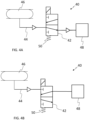
- FIGS. 4A-4B schematically illustrates components of an air supply control arrangement 40 according to one example of this disclosure, wherein a valve 42 is presented in two different states.
- FIGS. 4A and 4 B may, for instance, illustrate different states which correspond to the states of the valve 32 illustrated in FIGS. 2A and 2B , respectively.
- FIG. 4A illustrates the open second state when the lift axle is in its ride condition
- FIG. 4B illustrates the closed first state when the lift axle is in its lift condition.
- the air supply control arrangement 40 is intended to be used for a heavy-duty vehicle comprising a lift axle, which lift axle comprises a brake chamber (lift axle and brake chamber not illustrated in FIG. 4A ) .
- the air supply control arrangement 40 comprises said valve 42 configured to be arranged in an air supply passage 44 that enables pressurized air to be supplied from a pressurized air source 46 to the brake chamber of the lift axle.
- the pressurized air source 46 is illustrated in the form of a tank containing pressurized air. The tank may, for instance, become pressurized by means of a compressor. This disclosure is, however, not limited to using the air supply control arrangement 40 in connection with a specific type of pressurized air source 46.
- the pressurized air source 46 is not part of the actual air supply control arrangement 40, but merely forms part of the environment in which the air supply control arrangement 40 is to be installed and operated. In other examples, it may however be conceivable to include a pressurized air source 46 as part of the air supply control arrangement.
- the air supply control arrangement 40 also comprises a processing circuitry (such as indicated by the processing circuitry 34 in FIGS. 2A-2B ) configured to control the state of the valve 42, in line with the previous discussions.
- the air supply control arrangement 40 may, optionally, further comprise an electronically controlled brake valve device 48.
- the electronically controlled brake valve device 48 may receive pressurized air via the valve 42.
- the electronically controlled brake valve device 48 When the electronically controlled brake valve device 48 is opened, it allows received pressurized air to be passed to the brake chamber. Thus, the electronically controlled brake valve device 48 may be positioned between the valve 42 and the brake chamber with respect to the direction of flow of pressurized air. When the electronically controlled brake valve device 48 is closed, it prevents any received pressurized air from being passed to the brake chamber. The degree of the opening and/or the duration of the opening of the electronically controlled brake valve device 48 may be controlled by an electronic brake request received by the electronically controlled brake valve device 48.
- valve 42 is open in FIG. 4A allowing pressurized air to pass through the valve 42 along the air supply passage 44, and the valve 42 is closed in FIG. 4B , preventing pressurized air to pass through the valve 42 along the air supply passage 44.
- the closed state in FIG. 4B represents an example of a closed first state of the valve 42, which has been discussed elsewhere in this disclosure.
- the open state in FIG. 4A represents an open second state of the valve 42, which has also been discussed elsewhere in this disclosure.
- valve 42 when the valve 42 is in the closed first state ( FIG. 4B ), pressurized air is prevented from reaching the electronically controlled brake valve device 48, irrespectively or the latter being opened or closed, and thus pressurized air is prevented from reaching the brake chamber of the lift axle.
- the brake chamber of the lift axle will not receive any pressurized air and the brakes of the lift axle will not be activated.
- Other brake chambers associated with other axles having tires in contact with the road will still be allowed to receive pressurized air so that the associated brakes become activated.
- FIGS. 5A-5B schematically illustrates two electronic switches S1, S2 connected in series with a valve 42, such as the valve 42 illustrated in FIGS. 4A-4B .
- the processing circuitry may suitably be configured to determine that the lift axle is in its lift condition when two requirements are simultaneously satisfied.
- the processing circuitry may be configured such that it only determines that the lift axle is in the lift condition when both of the previously discussed comparisons indicate that this is indeed the case.
- FIGS. 5A and 5B A possible way of implementing this is shown in FIGS. 5A and 5B .
- the processing circuitry may comprise said first switch S1, which is normally open, and said second switch S2, which is also normally open. This is illustrated in FIG. 5A .
- the processing circuitry When the measurement values are lower than said predefined pressure value, the processing circuitry generates a first voltage signal which closes the first switch S 1. When the determined pressure oscillation amplitude P amp is lower than the predefined amplitude value the processing circuitry generates a second voltage signal which closes the second switch S2.
- the first switch S 1 and the second switch S2 are closed ( FIG. 5B )
- electricity is allowed to be supplied to the valve 42, and electrical energy may (in case of a solenoid valve) be converted into mechanical energy, thereby physically moving the valve 42 to the closed first state (e.g. as illustrated in FIG. 4B ) . Pressurized air is thus prevented from being supplied to the brake chamber.
- the valve 42 may suitably be a solenoid valve.
- the air supply control arrangement 40 may suitably comprise a spring device 50 which is configured to bias the valve 42 towards the open second state ( FIG. 4A ).
- the valve 42 will automatically allow pressurized air to be supplied to the electronically controlled brake valve device 48.
- the valve 42 being a solenoid valve, when it becomes energized, it should be with sufficient force to overcome the spring force, thus, allowing to the valve 42 to move to the closed first state ( FIG. 4B ).
- FIG. 6 schematically illustrates an air supply control arrangement 100 according to at least one example of this disclosure.
- FIG. 6 schematically illustrates an air supply control arrangement 100 according to one example of this disclosure and its relation to certain brake components.
- the air supply control arrangement 100 may comprise the valve 42 exemplified in FIGS. 4A-4B .
- another valve may be used instead.
- the air supply control arrangement 100 in FIG. 6 may further comprise an electronically controlled brake valve device 48.
- the electronically controlled brake valve device 48 may be controlled by a foot brake modulator 102 which translates the movements of a foot brake pedal 104 into a brake request 106.
- the electronically controlled brake valve device 48 receives the brake request 106 (e.g. in the form of an electric brake signal)
- the electronically controlled brake valve device 48 is opened.
- the electronically controlled brake valve device 48 is opened it allows pressurized air received in the electronically controlled brake valve device 48 to be passed to a brake chamber 108 of the lift axle.
- the electronically controlled brake valve device 48 is closed, pressurized air received in the electronically controlled brake valve device 48 is prevented from being passed to the brake chamber 108.
- the degree of the opening and/or the duration of the opening of the electronically controlled brake valve device 48 is controlled by the brake request 106 from the foot brake modulator 102.
- the valve 42 is arranged upstream of the electronically controlled brake valve device 48 and downstream of the pressurized air source 46.
- the pressurized air is allowed to be passed to the brake chamber, all the way from the pressurized air source 46.
- the valve 42 blocks pressurized air from reaching the electronically controlled brake valve device 48. In this latter case, there will be no pressurized air supplied from the pressurized air source 46 to the brake chamber 108 even if the electronically controlled brake valve device 48 receives a brake request 106 from the foot brake modulator 102.
- FIG. 6 also illustrates schematically a processing circuitry 110 which is in operative communication with a pressure sensor 112 measuring the pressure of a tire of the lift axle.
- the information 114 received by the processing circuitry 110 from the pressure sensor 112 is such that the processing circuitry 110 does not energize the valve 42 (therefore a control signal arrow from the processing circuitry 110 to the valve 42 is illustrated with a dashed line).
- the spring force of the spring device 50 keeps the valve 42 in the open second state shown in FIG. 6 .
- the information 114 received by the processing circuitry 110 will change and the processing circuitry 110 will accordingly energize the valve 42 to move it against the spring force of the spring device 50 so that the valve 42 reaches the closed first state.
- the processing circuitry 110 may instead control the electronically controlled brake valve device 48 independently and may override any brake request 106 from the foot brake modulator 102 when the lift axle is in the lift condition.
- FIGS. 7A-7B schematically illustrates methods 200, 300 according to at least some examples of this disclosure.
- FIG. 7A schematically illustrates a method 200 of controlling air supply to a brake chamber of a lift axle of a heavy-duty vehicle, the method 200 comprising:
- FIG. 7B schematically illustrates that an example 300 of the method 200 may further comprise:
- the methods discussed in this disclosure may suitably be executed by means of a processing circuitry, in particular by means of the processing circuitry of the air supply control arrangement of this disclosure, including any examples thereof.
- a processing circuitry in particular by means of the processing circuitry of the air supply control arrangement of this disclosure, including any examples thereof.
- other examples of the method are included in this disclosure, such as examples which correspond to actions that have been discussed in connection with various examples of the air supply control arrangement. Those actions may be performed by the processing circuitry when implementing such other examples of the method.
- FIG. 8 schematically illustrates an air supply control arrangement 400 according to at least yet another example of this disclosure.
- FIG. 8 schematically illustrates an air supply control arrangement 400 for a heavy-duty vehicle comprising a lift axle which comprises a brake chamber, the air supply control arrangement 400 comprising:
- the valve 402 in FIG. 8 may be an electronically controlled brake valve device, or may represent a separate valve, such as in FIG. 6 .
- the pressure sensor 412, the pressurized air source 406 and the brake chamber 408 have been illustrated with dashed lines, indicating that they do not need to form part of the air supply control arrangement 400 as such.
- the air supply control arrangement 400 may, for instance, also comprise the pressure sensor 412 and/or the pressurized air source 406.
- the pressure sensor discussed in this disclosure may, for instance, be any suitable pressure sensor used or usable in a TPMS (Tire Pressure Monitoring System).
- TPMS Transire Pressure Monitoring System
- the processing circuitry may suitably receive information from a respective pressure sensor of each one of a left tire and a right tire of the lift axle. In such case, if the information from at least one of the pressure sensors indicate that the lift axle is in its ride condition, then the processing circuitry will determine that the lift axle is in its ride condition, and thus allowing normal braking functionality for the lift axle, i.e. allowing pressurized air to be supplied to the respective brake chambers of the lift axle when a brake request has been made.
- FIG. 8 also encompasses examples in which the valve 402 and the processing circuitry 410 form an integrated unit installable as one part of the air supply control arrangement 400.
- solenoid valve has been illustrated in some of the drawing figures as example for a valve that may be moved between said closed first state and said open second state, it should be understood that this disclosure is not limited to a solenoid valve.
- the valve may be implemented in the form of any other suitable control valve which can be set in a closed first state and an open second state.
- the present disclosure also relates to a vehicle which comprises an air supply control arrangement, e.g. an air supply control arrangement according to any one of the examples in FIGS. 4A-4b , 6 and 8.
- a vehicle which comprises an air supply control arrangement, e.g. an air supply control arrangement according to any one of the examples in FIGS. 4A-4b , 6 and 8.
- Such a vehicle may for example be a vehicle like the one in FIG. 1 , or it may be another vehicle.
- Example 1 An air supply control arrangement for a heavy-duty vehicle comprising a lift axle which comprises a brake chamber, the air supply control arrangement comprising:
- Example 2 The air supply control arrangement according to Example 1, wherein the processing circuitry is further configured to compare the received measurement value with a predefined pressure value, wherein the processing circuitry is configured to control the valve to move to the closed first state upon determination that the lift axle is in a raised lift condition, wherein the processing circuitry is configured to determine that the lift axle is in its lift condition when the received measurement values are lower than said predefined pressure value.
- Example 3 The air supply control arrangement according to Example 1, wherein when the lift axle is in a lowered ride condition the measurement values vary in an oscillating manner due to the rotation of the tire, wherein the processing circuitry is configured to determine a pressure oscillation amplitude based on said received measurement values, wherein the processing circuitry is further configured to compare the determined pressure oscillation amplitude with a predefined amplitude value, wherein the processing circuitry is configured to control the valve to move to the closed first state upon determination that the lift axle is in a raised lift condition, wherein the processing circuitry is configured to determine that the lift axle is in its lift condition when the determined pressure oscillation amplitude is lower than the predefined amplitude value.
- Example 4 The air supply control arrangement according to Example 1, wherein when the lift axle is in a lowered ride condition the measurement values vary in an oscillating manner due to the rotation of the tire, wherein the processing circuitry is configured to determine a pressure oscillation amplitude based on said received measurement values, wherein the processing circuitry is further configured to:
- Example 5 The air supply control arrangement according to any one of Examples 1-4, comprising an electronically controlled brake valve device, which when opened allows pressurized air received in the electronically controlled brake valve device to be passed to the brake chamber, and when closed prevents pressurized air received in the electronically controlled brake valve device from being passed to the brake chamber, wherein the degree of the opening and/or the duration of the opening of the electronically controlled brake valve device is controlled by an electronic brake request received by the electronically controlled brake valve device.
- Example 6 The air supply control arrangement according to Example 5, wherein said valve forms part of said electronically controlled brake valve device.
- Example 7 The air supply control arrangement according to Example 5, further comprising:
- Example 8 The air supply control arrangement according to Example 7, further comprising:
- Example 9 The air supply control arrangement according to any one of Examples 1-8, wherein the valve is a solenoid valve actuated by an electronic signal from the processing circuitry.
- Example 10 The air supply control arrangement according to any one of Examples 1-9, wherein said valve and the processing circuitry form an integrated unit installable as one part of the air supply control arrangement.
- Example 11 The air supply control arrangement according to Example 4 or any one of Examples 5-10 when dependent on Example 4, wherein the processing circuitry comprises a first switch which is normally open, and a second switch which is normally open, wherein the first switch and second switch are connected in series to the valve, wherein when said measurement values are lower than said predefined pressure value a first voltage signal is generated and closes the first switch, and when the determined pressure oscillation amplitude is lower than the predefined amplitude value a second voltage signal is generated and closes the second switch, wherein when both the first switch and the second switch are closed, the valve is energized and moves to the closed first state.
- the processing circuitry comprises a first switch which is normally open, and a second switch which is normally open, wherein the first switch and second switch are connected in series to the valve, wherein when said measurement values are lower than said predefined pressure value a first voltage signal is generated and closes the first switch, and when the determined pressure oscillation amplitude is lower than the predefined amplitude value a second voltage signal is generated and close
- Example 12 The air supply control arrangement according to any one of Examples 1-11, further comprising said pressure sensor, from which the processing circuitry receives said measurement values.
- Example 13 A vehicle comprising the air supply control arrangement according to any of Examples 1-12.
- Example 14 A method of controlling air supply to a brake chamber of a lift axle of a heavy-duty vehicle, the method comprising:
- Example 15 The method according to Example 14, further comprising:
- Relative terms such as “below” or “above” or “upper” or “lower” or “horizontal” or “vertical” may be used herein to describe a relationship of one element to another element as illustrated in the Figures. It will be understood that these terms and those discussed above are intended to encompass different orientations of the device in addition to the orientation depicted in the Figures. It will be understood that when an element is referred to as being “connected” or “coupled” to another element, it can be directly connected or coupled to the other element, or intervening elements may be present. In contrast, when an element is referred to as being “directly connected” or “directly coupled” to another element, there are no intervening elements present.
Landscapes
- Engineering & Computer Science (AREA)
- Mechanical Engineering (AREA)
- Transportation (AREA)
- Chemical & Material Sciences (AREA)
- Combustion & Propulsion (AREA)
- Regulating Braking Force (AREA)
Abstract
Description
- The disclosure relates generally to an air supply control arrangement. In particular aspects, the disclosure relates to an air supply control arrangement for a heavy duty vehicle comprising a lift axle. This disclosure also relates to a method of controlling air supply to a brake chamber of a lift axle. The disclosure can be applied in heavy-duty vehicles, such as trucks, buses, and construction equipment. Although the disclosure may be described with respect to a particular vehicle, the disclosure is not restricted to any particular vehicle.
- A heavy-duty vehicle may be equipped with a lift axle that can be raised so that its tires do not touch the road surface, for example when driving without any cargo. When the vehicle is heavily loaded, the lift axle can be lowered so that the tires of the lift axle assist in supporting the heavy weight. Being able to raise the lift axle when not needed for load support improves fuel/battery economy. In existing systems, when brakes are applied, the service brakes are normally activated for all axles, including the lift axle, irrespective of if it is in its lifted condition or in its ride condition. Due to this, the consumption of the pressurized air used for braking is increased in each brake cycle. This leads to increase of the compressor duty cycle. For battery electric vehicles this will also reduce the drive range.
- According to a first aspect of the disclosure, there is provided an air supply control arrangement for a heavy-duty vehicle comprising a lift axle which comprises a brake chamber, the air supply control arrangement comprising:
- a valve configured to be arranged in an air supply passage that enables pressurized air to be supplied from a pressurized air source to a brake chamber of a lift axle of a heavy-duty vehicle, the valve having a closed first state in which pressurized air along the air supply passage is blocked by the valve and an open second state in which pressurized air is allowed to pass through the valve along the air supply passage,
- a processing circuitry configured to receive, from a pressure sensor, measurement values of the pressure inside a tire of the lift axle,
- It should be understood that although the present disclosure will, for convenience, mainly discuss brake chamber, tire, pressure sensor in singular form, it should be understood that the teachings of the present disclosure are fully implementable for plural forms. In particular, the teachings of the present disclosure may advantageously be implemented for both a left tire and a right tire of the lift axle, each one having a respective associated pressure sensor providing measurement values to the processing circuitry, and each one being associated with a respective brake chamber to which the supply of the pressurized air may be controlled.
- Optionally, in some examples, including in at least one preferred example, the processing circuitry is further configured to compare the received measurement value with a predefined pressure value, wherein the processing circuitry is configured to control the valve to move to the closed first state upon determination that the lift axle is in a raised lift condition, wherein the processing circuitry is configured to determine that the lift axle is in its lift condition when the received measurement values are lower than said predefined pressure value. A technical benefit may include that this provides a simple and straightforward determination of whether or not the lift axle is in the lift condition. By setting a predefined pressure value, which functions as a threshold, measurement values that are lower than said threshold can be conveniently identified and may be considered as indicative of the lift axle being in lift condition (under the presumption that there is no load or less load on the tires when the lift axle is in the lift condition compared to when the lift axle is in the ride condition). The predefined pressure value may be set differently/individually for different types of vehicles, and may suitably be done by collecting data from initially performed pressure measurements in both the lift condition and the ride condition.
- Optionally, in some examples, including in at least one preferred example, when the lift axle is in a lowered ride condition, the measurement values vary in an oscillating manner due to the rotation of the tire, wherein the processing circuitry is configured to determine a pressure oscillation amplitude based on said received measurement values, wherein the processing circuitry is further configured to compare the determined pressure oscillation amplitude with a predefined amplitude value, wherein the processing circuitry is configured to control the valve to move to the closed first state upon determination that the lift axle is in a raised lift condition, wherein the processing circuitry is configured to determine that the lift axle is in its lift condition when the determined pressure oscillation amplitude is lower than the predefined amplitude value. A technical benefit may include that, in the event of a puncture or similar leakage, the pressure in the tire will be reduced, and might make it difficult to determine the current condition of the lift axle relying purely on the magnitude of the measured values. Nevertheless, if the lift axle is in its ride condition there will, even with a puncture, be pressure oscillations due to the rotation of the tire, whereas when the lift axle is in its lift condition and the tires are idle, there will be no or very little pressure oscillations.
- Optionally, in some examples, including in at least one preferred example, when the lift axle is in a lowered ride condition, the measurement values vary in an oscillating manner due to the rotation of the tire, wherein the processing circuitry is configured to determine a pressure oscillation amplitude based on said received measurement values, wherein the processing circuitry is further configured to:
- compare the received measurement values with a predefined pressure value, and
- compare the determined pressure oscillation amplitude with a predefined amplitude value,
- Optionally, in some examples, including in at least one preferred example, the air supply control arrangement may comprise an electronically controlled brake valve device, which when opened allows pressurized air received in the electronically controlled brake valve device to be passed to the brake chamber, and when closed prevents pressurized air received in the electronically controlled brake valve device from being passed to the brake chamber, wherein the degree of the opening and/or the duration of the opening of the electronically controlled brake valve device is controlled by an electronic brake request received by the electronically controlled brake valve device. A technical benefit may include that such an electronically controlled brake valve device provides an efficient way of transmitting a brake request from a driver to the brake chamber.
- Optionally, in some examples, including in at least one preferred example, said valve forms part of said electronically controlled brake valve device. A technical benefit may include that, in this example, there is no need to provide a separate valve for preventing the supply of pressurized air to the brake chamber when the lift axle is in its lift condition. Thus, the electronically controlled brake valve device may be appropriately configured to receive instructions form the processing circuitry to prevent pressurized air to be supplied to the brake chamber when the processing circuitry has determined that the lift axle is in its lift condition. In this way, even though the driver applies the brakes of the vehicles, issuing a brake request to the electronically controlled brake valve device, there will be no pressurized air supplied to the brake chamber if the lift axle is in its lift condition.
- Optionally, in some examples, including in at least one preferred example, the air supply control arrangement may further comprise:
- a supply passage,
- a pressurized air source for supplying pressurized air to the electronically controlled brake valve device along said supply passage,
- A technical benefit may include that, even though the driver applies the brakes of the vehicle, e.g. pressing the foot brake pedal, there will be no braking action on the lift axle if the valve is in its closed first state, i.e. if the lift axle is in its lifted condition. Hereby, pressurized air is not wasted on braking the lift axle when it is in its lifted condition. When a driver presses the foot brake pedal an electronic brake request may be sent to the electronically controlled brake valve device (e.g. from a foot brake modulator translating the movement of the foot brake pedal into an electric signal to the brake valve device). The electronically controlled brake valve device will therefore open in line with the received electronic brake request, but there will be no braking action if the valve is in its closed first state, i.e. if the lift axle is in its lifted condition. Thus, when the valve is in the open second state and the electronically controlled brake valve device receives an electronic brake request, then pressurized air is allowed to be passed to the brake chamber, whereas when the valve is in the closed first state and the electronically controlled brake valve device receives an electronic brake request, the valve blocks pressurized air from the pressurized air source from reaching the electronically controlled brake valve device.
- Optionally, in some examples, including in at least one preferred example, the air supply control arrangement may further comprise:
- a spring device configured to bias the valve towards said open second state, such that in case of pressure monitoring failure, the valve automatically allows pressurized air to be supplied to the electronically controlled brake valve device. A technical benefit may include, that by providing a spring device, as long as the pressure monitoring (pressure measurements and the transfer of information of the pressure measurements to the processing circuitry) is functional the valve can work as intended, however, if the processing circuitry for some reason does not receive any input from the pressure sensor, e.g. due to malfunctioning pressure sensor, the spring device can move the valve to the open second state.
- Optionally, in some examples, including in at least one preferred example, the valve is a solenoid valve actuated by an electronic signal from the processing circuitry. A technical benefit may include that a solenoid valve may be efficiently controlled by electronic signals, without requiring any additional mechanical control.
- In some examples, including in at least one preferred example, optionally said valve and the processing circuitry form an integrated unit installable as one part of the air supply control arrangement. A technical benefit may include that it facilitates installation of the air supply control arrangement.
- This disclosure includes electronics and electronic instructions for implementing the arrangement and processes described herein, which may be embodied and/or collectively described as a processing circuitry. The processing circuitry may include electrical switches that are triggered by electrical signals, such as voltage signals, to become closed, and/or may include electrical switches that are triggered by electrical signals, such as voltage signals, to become opened. The processing circuitry unit may include a microprocessor, microcontroller, programmable digital signal processor, computer, or another programmable device. The processing circuitry may also, or instead, include an application specific integrated circuit, a programmable gate array or programmable array logic, a programmable logic device, or a digital signal processor. Where it includes a programmable device such as the microprocessor, microcontroller or programmable digital signal processor mentioned above, the processor may further include computer executable code that controls operation of the programmable device as disclosed herein.
- Optionally, in some examples, including in at least one preferred example, the processing circuitry may comprise a first switch which is normally open, and a second switch which is normally open, wherein the first switch and second switch are connected in series to the valve, wherein when said measurement values are lower than said predefined pressure value a first voltage signal is generated and closes the first switch, and when the determined pressure oscillation amplitude is lower than the predefined amplitude value a second voltage signal is generated and closes the second switch, wherein when both the first switch and the second switch are closed, the valve is energized and moves to the closed first state. A technical benefit may include that, by connecting the first switch and the second switch in series with the valve, both switches need to be closed to energize the valve, thereby providing redundancy and an additional level of safety. The valve in this case may, for example, be a solenoid valve.
- Optionally, in some examples, including in at least one preferred example, the air supply control arrangement may further comprise said pressure sensor, from which the processing circuitry receives said measurement values. A technical benefit may include that the processing circuitry and the pressure sensor may be operatively fine-tuned for improved communication. However, it should be understood that in other examples the pressure sensor does not need to be part of the air supply control arrangement, and in such cases the air supply control arrangement may be retrofitted to a vehicle which is already provided with a pressure sensor that measures tire pressure at the lift axle.
- According to a second aspect of the disclosure, there is provided a vehicle comprising the air supply control arrangement according to the first aspect, including any example thereof. The second aspect of the disclosure may, similarly to the first aspect seek to avoid unnecessary braking of the wheels of the lift axle, and thus reduce unnecessary consumption of pressurized air. A technical benefit may include that the brakes of the lift axle do not need to become engaged when the wheels and tires of the lift axle are lifted and thus do not contribute to the travelling motion of the vehicle.
- According to a third aspect of the disclosure, there is provided a method of controlling air supply to a brake chamber of a lift axle of a heavy-duty vehicle, the method comprising:
- monitoring the pressure inside a tire of the lift axle,
- determining, based on the monitored pressure, whether the lift axle is in its raised lift condition or in its lowered ride condition, and
- controlling, upon determination that the lift axle is in its raised lift condition, a valve to be closed so as to prevent pressurized air from being supplied from a pressurized air source to the brake chamber.
- The third aspect of the disclosure may, similarly to the first and second aspects seek to avoid unnecessary braking of the wheels of the lift axle, and thus reduce unnecessary consumption of pressurized air. A technical benefit may include that the brakes of the lift axle do not need to become engaged when the wheels and tires of the lift axle are lifted and thus do not contribute to the travelling motion of the vehicle.
- Optionally, in some examples, including in at least one preferred example, the method may further comprise:
- receiving, from a pressure sensor, measurement values of the pressure inside a tire of the lift axle, wherein when the lift axle is in a lowered ride condition the measurement values vary in an oscillating manner due to the rotation of the tire,
- determining a pressure oscillation amplitude based on said received measurement values,
- comparing the received measurement values with a predefined pressure value,
- comparing the determined pressure oscillation amplitude with a predefined amplitude value,
- determining that the lift axle is in its lift condition when the received measurement values are lower than said predefined pressure value simultaneously with the determined pressure oscillation amplitude being lower than the predefined amplitude value, and
- controlling the valve to be closed upon determination that the lift axle is in its raised lift condition.
- Technical benefits may correspond to those discussed in relation to the first aspect, including any example thereof. The method of the third aspect, including any example thereof, may be fully or partly performed by a processing circuitry, such as a processing circuitry of the air supply control arrangement of the first aspect, including any example thereof.
- According to a fourth aspect of this disclosure, there is provided an air supply control arrangement for a heavy-duty vehicle comprising a lift axle which comprises a brake chamber, the air supply control arrangement comprising:
- a valve configured to be arranged in an air supply passage that enables pressurized air to be supplied from a pressurized air source to a brake chamber of a lift axle of a heavy-duty vehicle, the valve having a closed first state in which pressurized air along the air supply passage is blocked by the valve and an open second state in which pressurized air is allowed to pass through the valve along the air supply passage,
- a processing circuitry configured to receive, from a pressure sensor, measurement values of the pressure inside a tire of the lift axle, wherein when the lift axle is in a lowered ride condition the measurement values vary in an oscillating manner due to the rotation of the tire, wherein the processing circuitry is configured to determine a pressure oscillation amplitude based on said received measurement values,
- wherein the processing circuitry is further configured to:
- compare the received measurement values with a predefined pressure value, and
- compare the determined pressure oscillation amplitude with a predefined amplitude value,
- wherein the processing circuitry is configured to control the valve to move to the closed first state upon determination that the lift axle has been raised from its ride condition to its lift condition, wherein the processing circuitry is configured to determine that the lift axle is in its lift condition when the received measurement values are lower than said predefined pressure value simultaneously with the determined pressure oscillation amplitude being lower than the predefined amplitude value. Technical benefits may include those discussed in connection with the first aspect, including any example thereof.
- wherein the processing circuitry is further configured to:
- The disclosed aspects, examples (including any preferred examples), and/or accompanying claims may be suitably combined with each other as would be apparent to anyone of ordinary skill in the art. Additional features and advantages are disclosed in the following description, claims, and drawings, and in part will be readily apparent therefrom to those skilled in the art or recognized by practicing the disclosure as described herein.
- Examples are described in more detail below with reference to the appended drawings.
-
FIG. 1 schematically illustrates a vehicle according to one example of this disclosure. -
FIGS. 2A-2B schematically illustrate different conditions of a lift axle. -
FIG. 3 schematically illustrates how pressure measurement values for a tire of a lift axle may vary when a vehicle is travelling with the lift axle in a ride condition. -
FIGS. 4A-4B schematically illustrates components of an air supply control arrangement according to one example of this disclosure, wherein a valve is presented in two different states. -
FIGS. 5A-5B schematically illustrates two electronic switches connected in series with a valve. -
FIG. 6 schematically illustrates an air supply control arrangement according to at least one example of this disclosure. -
FIGS. 7A-7B schematically illustrates methods according to at least some examples of this disclosure. -
FIG. 8 schematically illustrates an air supply control arrangement according to at least yet another example of this disclosure. - The detailed description set forth below provides information and examples of the disclosed technology with sufficient detail to enable those skilled in the art to practice the disclosure.
- The present disclosure teaches that consumption of the pressurized air used for braking may be saved when the lift axle is in its lift condition. This leads to decrease of the compressor duty cycle. For battery electric vehicles this will also increase the drive range.
-
FIG. 1 schematically illustrates avehicle 1 according to one example of this disclosure. More specifically, the illustratedvehicle 1 is a heavy-duty vehicle combination which comprises atractor unit 2 and atrailer unit 4. Thetractor unit 2 has threewheel axles wheel axles tractor unit 2 has afront axle 6 and tworear axles rear axles rear axles pusher axle 8 in front of adrive axle 10. In other examples, the tworear axles tag axle 10 behind adrive axle 8. It should be understood that the teachings of this disclosure may be implemented for any lift axle, irrespective of its location. Indeed, the teachings of this disclosure are not limited to lift axles on tractor units, but may be implemented for lift axles on trailer units as well, such as full trailers or semi-trailers. Additionally, the teachings of the present disclosure is not limited to a particular vehicle propulsion system, i.e., the teachings herein may be implemented for vehicles propelled by internal combustion engines, traction batteries, fuel cells, hybrid systems, etc. Furthermore, the teachings of the present disclosure may be implemented for driver-operated vehicles and for autonomous (self-driving) vehicles. -
FIGS. 2A-2B schematically illustrate different conditions of a lift axle. Starting withFIG. 2A , there is schematically illustrated a part of achassis 20 of a vehicle, for example thevehicle 1 inFIG. 1 or another vehicle. Two left wheels that carrytires respective wheel axle rearmost axle 28 may be drive axle, while the other one is alift axle 26. InFIG. 2A thelift axle 26 is in its lowered ride condition. Thus, thetires lift axle 26 and thedrive axle 28 are in contact with the ground, contributing to carrying the load of the vehicle. - In
FIG. 2A , an airsupply control arrangement 30 is schematically indicated. The airsupply control arrangement 30 comprises avalve 32.FIG. 2A just indicates very schematically avalve 32. A more detailed example of a valve will be discussed in relation to other drawing figures. InFIG. 2A , the airsupply control arrangement 30 also comprises aprocessing circuitry 34. Apressure sensor 36 is in thetire 22 of thelift axle 26. Theprocessing circuitry 34 is configured to receive, from thepressure sensor 36, measurement values of the pressure inside thetire 22 of thelift axle 26. Thepressure sensor 36 may suitably communicate the measurement values wirelessly, however, wired communication is also conceivable. Based on the received measurement values, theprocessing circuitry 34 whether thelift axle 26 is in its raised lift condition or in its lowered ride condition. Theprocessing circuitry 34 is further configured to control thevalve 32 to move to a closed first state upon determination that thelift axle 26 has been raised from its ride condition to its lift condition, which lift condition will now be discussed in relation toFIG. 2B . - Turning now to
FIG. 2B , thelift axle 26 is now show in its lift condition, thus not contributing to supporting the vehicle load. Thelift axle 26 may, for instance, be provided in this lift condition, when the vehicle does not carry any considerable weight, whereby ground friction is reduced by lifting thelift axle 26. When thelift axle 26 is in this lift condition, thetire 22 is subjected to less load (or even no load) compared to when thelift axle 26 is in the ride condition. This in turn means that the pressure inside thetire 22 will be lower in this lift condition (FIG. 2B ) compared to in the ride condition (FIG. 2A ) of thelift axle 26. Theprocessing circuitry 34 will based on the received measurement values determine which is the current condition of thelift axle 26. - Although not illustrate in
FIGS. 2A and 2B (but which will be discussed in more detail in connection with other drawing figures), thelift axle 26 comprises a brake chamber which may receive pressurized air upon a brake request, whereby a frictional force is applied to an associated wheel (such as to a brake disc or to a brake drum of the wheel). However, according to the present disclosure, the pressurized air may be prevented from being supplied to the brake chamber when thelift axle 26 is in the lift condition, thereby avoiding unnecessary air and energy consumption. Thevalve 32 is configured to be arranged in an air supply passage that enables pressurized air to be supplied from a pressurized air source to the brake chamber. Thevalve 32 has a closed first state in which pressurized air along the air supply passage is blocked by thevalve 32 and an open second state in which pressurized air is allowed to pass through thevalve 32 along the air supply passage. Theprocessing circuitry 34 is configured to control thevalve 32 to move to the closed first state upon determination that thelift axle 26 has been raised from its ride condition (FIG. 2A ) to its lift condition (FIG. 2B ). -
FIG. 3 schematically illustrates how pressure measurement values for a tire of a lift axle may vary when a vehicle is travelling with the lift axle in a ride condition. In particular,FIG. 3 schematically illustrates how the pressure P in the tire of the lift axle may vary in relation to the angular distance ωt travelled by the tire (where ω is the angular speed of the tire, and t is elapsed time). The processing circuitry (such as theprocessing circuitry 34 inFIGS. 2A-2B ) may be configured to compare the received measurement values with a predefined pressure value. As long as the received measurement values are above the predefined pressure value, the processing circuitry may interpret this as the lift axle being in the ride condition. However, when the measurement values fall below the predefined pressure value, the processing circuitry may interpret this as the lift axle being raised to the lift condition. As illustrated inFIG. 3 , when the lift axle is in the ride condition the measurement values will vary in an oscillating manner due to the rotation of the tire. In the lift condition, with the tire being substantially idle, there will be no or just very small oscillations. The processing circuitry may therefore be configured to determine a pressure oscillation amplitude Pamp based on said received measurement values and compare it with a predefined amplitude value. As long as the determined pressure oscillation amplitude Pamp is larger than the predefined amplitude value, the processing circuitry may interpret this as the lift axle being in the ride condition. However, when the determined pressure oscillation amplitude Pamp falls below the predefined amplitude value, the processing circuitry may interpret this as the lift axle being raised to the lift condition. As an additional measure of safety, the processing circuitry may suitably be configured to perform both of the above discussed comparisons. Such redundancy avoids incorrect interpretation in case of for example an air leakage in ride condition, in which case the pressure measurement values may fall below the predefined pressure value (which could be interpreted as lift condition), but because there will still be oscillations, the result of the amplitude comparison will correctly be interpreted as the ride condition. Thus, when using such redundancy, the results of both comparisons should be indicative of the lift axle being in the lift condition before the processing circuitry controls the valve to prevent pressurized air supply to the brake chamber. Hereby, the risk of inadvertently disabling the braking functionality when the lift axle is in the ride condition is reduced. The measurement values may suitably be received by the processing circuitry in a continuous manner from the pressure sensor, although discrete/intermittent informational transfer is also conceivable. -
FIGS. 4A-4B schematically illustrates components of an airsupply control arrangement 40 according to one example of this disclosure, wherein avalve 42 is presented in two different states.FIGS. 4A and 4 B may, for instance, illustrate different states which correspond to the states of thevalve 32 illustrated inFIGS. 2A and 2B , respectively. Thus,FIG. 4A illustrates the open second state when the lift axle is in its ride condition, whileFIG. 4B illustrates the closed first state when the lift axle is in its lift condition. - Starting with
FIG. 4A , the airsupply control arrangement 40 is intended to be used for a heavy-duty vehicle comprising a lift axle, which lift axle comprises a brake chamber (lift axle and brake chamber not illustrated inFIG. 4A ). The airsupply control arrangement 40 comprises saidvalve 42 configured to be arranged in anair supply passage 44 that enables pressurized air to be supplied from apressurized air source 46 to the brake chamber of the lift axle. InFIG. 4A thepressurized air source 46 is illustrated in the form of a tank containing pressurized air. The tank may, for instance, become pressurized by means of a compressor. This disclosure is, however, not limited to using the airsupply control arrangement 40 in connection with a specific type ofpressurized air source 46. Indeed, in at least some examples, thepressurized air source 46 is not part of the actual airsupply control arrangement 40, but merely forms part of the environment in which the airsupply control arrangement 40 is to be installed and operated. In other examples, it may however be conceivable to include apressurized air source 46 as part of the air supply control arrangement. Although not illustrated, the airsupply control arrangement 40 also comprises a processing circuitry (such as indicated by theprocessing circuitry 34 inFIGS. 2A-2B ) configured to control the state of thevalve 42, in line with the previous discussions. The airsupply control arrangement 40 may, optionally, further comprise an electronically controlledbrake valve device 48. The electronically controlledbrake valve device 48 may receive pressurized air via thevalve 42. When the electronically controlledbrake valve device 48 is opened, it allows received pressurized air to be passed to the brake chamber. Thus, the electronically controlledbrake valve device 48 may be positioned between thevalve 42 and the brake chamber with respect to the direction of flow of pressurized air. When the electronically controlledbrake valve device 48 is closed, it prevents any received pressurized air from being passed to the brake chamber. The degree of the opening and/or the duration of the opening of the electronically controlledbrake valve device 48 may be controlled by an electronic brake request received by the electronically controlledbrake valve device 48. - As can be seen in
FIGS. 4A and 4B , thevalve 42 is open inFIG. 4A allowing pressurized air to pass through thevalve 42 along theair supply passage 44, and thevalve 42 is closed inFIG. 4B , preventing pressurized air to pass through thevalve 42 along theair supply passage 44. The closed state inFIG. 4B represents an example of a closed first state of thevalve 42, which has been discussed elsewhere in this disclosure. The open state inFIG. 4A represents an open second state of thevalve 42, which has also been discussed elsewhere in this disclosure. - As can be understood, when the
valve 42 is in the closed first state (FIG. 4B ), pressurized air is prevented from reaching the electronically controlledbrake valve device 48, irrespectively or the latter being opened or closed, and thus pressurized air is prevented from reaching the brake chamber of the lift axle. Thus, even though a brake request has been made, the brake chamber of the lift axle will not receive any pressurized air and the brakes of the lift axle will not be activated. Other brake chambers associated with other axles having tires in contact with the road, will still be allowed to receive pressurized air so that the associated brakes become activated. -
FIGS. 5A-5B schematically illustrates two electronic switches S1, S2 connected in series with avalve 42, such as thevalve 42 illustrated inFIGS. 4A-4B . As mentioned before in connection with the discussion ofFIG. 3 , for additional safety, the processing circuitry may suitably be configured to determine that the lift axle is in its lift condition when two requirements are simultaneously satisfied. In particular, the processing circuitry may be configured such that it only determines that the lift axle is in the lift condition when both of the previously discussed comparisons indicate that this is indeed the case. A possible way of implementing this is shown inFIGS. 5A and 5B . The processing circuitry may comprise said first switch S1, which is normally open, and said second switch S2, which is also normally open. This is illustrated inFIG. 5A . Thus, electric current does not pass through the open switches S1 and S2. The first switch S1 and the second switch S2 are connected in series to thevalve 42. This means that as long as at least one of the switches S1, S2 is open, electric current will not be allowed to pass via the switches S1, S2 to thevalve 42. - When the measurement values are lower than said predefined pressure value, the processing circuitry generates a first voltage signal which closes the
first switch S 1. When the determined pressure oscillation amplitude Pamp is lower than the predefined amplitude value the processing circuitry generates a second voltage signal which closes the second switch S2. When both thefirst switch S 1 and the second switch S2 are closed (FIG. 5B ), electricity is allowed to be supplied to thevalve 42, and electrical energy may (in case of a solenoid valve) be converted into mechanical energy, thereby physically moving thevalve 42 to the closed first state (e.g. as illustrated inFIG. 4B ). Pressurized air is thus prevented from being supplied to the brake chamber. As mentioned, thevalve 42 may suitably be a solenoid valve. As also mentioned, when at least one of the switches S1, S2 is open, or when both switches S1, S2 are open (FIG. 5A ) the voltage signal does not reach thevalve 42, which is therefore not energized, wherefore thevalve 42 will stay in, or move to, the open second state (FIG. 4A ). In this state, thevalve 42 does not prevent pressurized air from passing through thevalve 42. - As can be seen in
FIGS. 4A and 4B , the airsupply control arrangement 40 may suitably comprise aspring device 50 which is configured to bias thevalve 42 towards the open second state (FIG. 4A ). Thus, in case of pressure monitoring failure, thevalve 42 will automatically allow pressurized air to be supplied to the electronically controlledbrake valve device 48. In case of thevalve 42 being a solenoid valve, when it becomes energized, it should be with sufficient force to overcome the spring force, thus, allowing to thevalve 42 to move to the closed first state (FIG. 4B ). -
FIG. 6 schematically illustrates an airsupply control arrangement 100 according to at least one example of this disclosure. In particular,FIG. 6 schematically illustrates an airsupply control arrangement 100 according to one example of this disclosure and its relation to certain brake components. As illustrated inFIG. 6 , the airsupply control arrangement 100 may comprise thevalve 42 exemplified inFIGS. 4A-4B . However, in other examples, another valve may be used instead. - The air
supply control arrangement 100 inFIG. 6 may further comprise an electronically controlledbrake valve device 48. The electronically controlledbrake valve device 48 may be controlled by afoot brake modulator 102 which translates the movements of afoot brake pedal 104 into abrake request 106. Thus, when the electronically controlledbrake valve device 48 receives the brake request 106 (e.g. in the form of an electric brake signal), the electronically controlledbrake valve device 48 is opened. When the electronically controlledbrake valve device 48 is opened it allows pressurized air received in the electronically controlledbrake valve device 48 to be passed to abrake chamber 108 of the lift axle. When the electronically controlledbrake valve device 48 is closed, pressurized air received in the electronically controlledbrake valve device 48 is prevented from being passed to thebrake chamber 108. The degree of the opening and/or the duration of the opening of the electronically controlledbrake valve device 48 is controlled by thebrake request 106 from thefoot brake modulator 102. - As can be seen in
FIG. 6 , thevalve 42 is arranged upstream of the electronically controlledbrake valve device 48 and downstream of thepressurized air source 46. When thevalve 42 is in the illustrated open second state and the electronically controlledbrake valve device 48 receives abrake request 106, the pressurized air is allowed to be passed to the brake chamber, all the way from thepressurized air source 46. However, when thevalve 42 is in the closed first state (i.e. lift axle is in lifted condition), then thevalve 42 blocks pressurized air from reaching the electronically controlledbrake valve device 48. In this latter case, there will be no pressurized air supplied from thepressurized air source 46 to thebrake chamber 108 even if the electronically controlledbrake valve device 48 receives abrake request 106 from thefoot brake modulator 102. -
FIG. 6 also illustrates schematically aprocessing circuitry 110 which is in operative communication with apressure sensor 112 measuring the pressure of a tire of the lift axle. When the lift axle is in a ride mode, theinformation 114 received by theprocessing circuitry 110 from thepressure sensor 112 is such that theprocessing circuitry 110 does not energize the valve 42 (therefore a control signal arrow from theprocessing circuitry 110 to thevalve 42 is illustrated with a dashed line). Thus, the spring force of thespring device 50 keeps thevalve 42 in the open second state shown inFIG. 6 . If the lift axle is later lifted, theinformation 114 received by theprocessing circuitry 110 will change and theprocessing circuitry 110 will accordingly energize thevalve 42 to move it against the spring force of thespring device 50 so that thevalve 42 reaches the closed first state. - It should be understood that in other examples the
separate valve 42 may be omitted. In such cases theprocessing circuitry 110 may instead control the electronically controlledbrake valve device 48 independently and may override anybrake request 106 from thefoot brake modulator 102 when the lift axle is in the lift condition. -
FIGS. 7A-7B schematically illustratesmethods FIG. 7A schematically illustrates amethod 200 of controlling air supply to a brake chamber of a lift axle of a heavy-duty vehicle, themethod 200 comprising: - monitoring, 201, the pressure inside a tire of the lift axle,
- determining, 202, based on the monitored pressure, whether the lift axle is in its raised lift condition or in its lowered ride condition, and
- controlling, 203, upon determination that the lift axle is in its raised lift condition, a valve to be closed so as to prevent pressurized air from being supplied from a pressurized air source to the brake chamber.
-
FIG. 7B schematically illustrates that an example 300 of themethod 200 may further comprise: - receiving, 301, from a pressure sensor, measurement values of the pressure inside a tire of the lift axle, wherein when the lift axle is in a lowered ride condition the measurement values vary in an oscillating manner due to the rotation of the tire,
- determining, 302, a pressure oscillation amplitude based on said received measurement values,
- comparing, 303, the received measurement values with a predefined pressure value,
- comparing, 304, the determined pressure oscillation amplitude with a predefined amplitude value,
- determining, 305, that the lift axle is in its lift condition when the received measurement values are lower than said predefined pressure value simultaneously with the determined pressure oscillation amplitude being lower than the predefined amplitude value, and - controlling, 306, the valve to be closed upon determination that the lift axle is in its raised lift condition.
- The methods discussed in this disclosure, such as the
methods FIGS. 7A-7B may suitably be executed by means of a processing circuitry, in particular by means of the processing circuitry of the air supply control arrangement of this disclosure, including any examples thereof. Furthermore, other examples of the method are included in this disclosure, such as examples which correspond to actions that have been discussed in connection with various examples of the air supply control arrangement. Those actions may be performed by the processing circuitry when implementing such other examples of the method. -
FIG. 8 schematically illustrates an airsupply control arrangement 400 according to at least yet another example of this disclosure. In particular,FIG. 8 schematically illustrates an airsupply control arrangement 400 for a heavy-duty vehicle comprising a lift axle which comprises a brake chamber, the airsupply control arrangement 400 comprising: - a
valve 402 configured to be arranged in anair supply passage 404 that enables pressurized air to be supplied from apressurized air source 406 to abrake chamber 408 of a lift axle of a heavy-duty vehicle, thevalve 402 having a closed first state in which pressurized air along theair supply passage 404 is blocked by thevalve 402 and an open second state in which pressurized air is allowed to pass through thevalve 402 along theair supply passage 404, - a
processing circuitry 410 configured to receive, from apressure sensor 412, measurement values 414 of the pressure inside a tire of the lift axle, - The
valve 402 inFIG. 8 may be an electronically controlled brake valve device, or may represent a separate valve, such as inFIG. 6 . Thepressure sensor 412, thepressurized air source 406 and thebrake chamber 408 have been illustrated with dashed lines, indicating that they do not need to form part of the airsupply control arrangement 400 as such. However, in other examples, the airsupply control arrangement 400 may, for instance, also comprise thepressure sensor 412 and/or thepressurized air source 406. - The pressure sensor discussed in this disclosure may, for instance, be any suitable pressure sensor used or usable in a TPMS (Tire Pressure Monitoring System). Although the drawings have only been focused on one pressure sensor and one associated tire of the lift axle, it should be understood that the processing circuitry may suitably receive information from a respective pressure sensor of each one of a left tire and a right tire of the lift axle. In such case, if the information from at least one of the pressure sensors indicate that the lift axle is in its ride condition, then the processing circuitry will determine that the lift axle is in its ride condition, and thus allowing normal braking functionality for the lift axle, i.e. allowing pressurized air to be supplied to the respective brake chambers of the lift axle when a brake request has been made.
- Furthermore, although the
processing circuitry 410 and thevalve 402 inFIG. 8 have functionally been illustrated as two separate components, it should be understood that structurally, they may be integrated as one module. Thus,FIG. 8 also encompasses examples in which thevalve 402 and theprocessing circuitry 410 form an integrated unit installable as one part of the airsupply control arrangement 400. - Furthermore, although a solenoid valve has been illustrated in some of the drawing figures as example for a valve that may be moved between said closed first state and said open second state, it should be understood that this disclosure is not limited to a solenoid valve. The valve may be implemented in the form of any other suitable control valve which can be set in a closed first state and an open second state.
- As has been explained herein, the present disclosure also relates to a vehicle which comprises an air supply control arrangement, e.g. an air supply control arrangement according to any one of the examples in
FIGS. 4A-4b ,6 and 8. Such a vehicle, may for example be a vehicle like the one inFIG. 1 , or it may be another vehicle. - Example 1: An air supply control arrangement for a heavy-duty vehicle comprising a lift axle which comprises a brake chamber, the air supply control arrangement comprising:
- a valve configured to be arranged in an air supply passage that enables pressurized air to be supplied from a pressurized air source to a brake chamber of a lift axle of a heavy-duty vehicle, the valve having a closed first state in which pressurized air along the air supply passage is blocked by the valve and an open second state in which pressurized air is allowed to pass through the valve along the air supply passage,
- a processing circuitry configured to receive, from a pressure sensor, measurement values of the pressure inside a tire of the lift axle,
- Example 2: The air supply control arrangement according to Example 1, wherein the processing circuitry is further configured to compare the received measurement value with a predefined pressure value, wherein the processing circuitry is configured to control the valve to move to the closed first state upon determination that the lift axle is in a raised lift condition, wherein the processing circuitry is configured to determine that the lift axle is in its lift condition when the received measurement values are lower than said predefined pressure value.
- Example 3: The air supply control arrangement according to Example 1, wherein when the lift axle is in a lowered ride condition the measurement values vary in an oscillating manner due to the rotation of the tire, wherein the processing circuitry is configured to determine a pressure oscillation amplitude based on said received measurement values, wherein the processing circuitry is further configured to compare the determined pressure oscillation amplitude with a predefined amplitude value, wherein the processing circuitry is configured to control the valve to move to the closed first state upon determination that the lift axle is in a raised lift condition, wherein the processing circuitry is configured to determine that the lift axle is in its lift condition when the determined pressure oscillation amplitude is lower than the predefined amplitude value.
- Example 4: The air supply control arrangement according to Example 1, wherein when the lift axle is in a lowered ride condition the measurement values vary in an oscillating manner due to the rotation of the tire, wherein the processing circuitry is configured to determine a pressure oscillation amplitude based on said received measurement values, wherein the processing circuitry is further configured to:
- compare the received measurement values with a predefined pressure value, and
- compare the determined pressure oscillation amplitude with a predefined amplitude value,
- Example 5: The air supply control arrangement according to any one of Examples 1-4, comprising an electronically controlled brake valve device, which when opened allows pressurized air received in the electronically controlled brake valve device to be passed to the brake chamber, and when closed prevents pressurized air received in the electronically controlled brake valve device from being passed to the brake chamber, wherein the degree of the opening and/or the duration of the opening of the electronically controlled brake valve device is controlled by an electronic brake request received by the electronically controlled brake valve device.
- Example 6: The air supply control arrangement according to Example 5, wherein said valve forms part of said electronically controlled brake valve device.
- Example 7: The air supply control arrangement according to Example 5, further comprising:
- a supply passage,
- a pressurized air source for supplying pressurized air to the electronically controlled brake valve device along said supply passage,
- Example 8: The air supply control arrangement according to Example 7, further comprising:
- a spring device configured to bias the valve towards said open second state, such that in case of pressure monitoring failure, the valve automatically allows pressurized air to be supplied to the electronically controlled brake valve device.
- Example 9: The air supply control arrangement according to any one of Examples 1-8, wherein the valve is a solenoid valve actuated by an electronic signal from the processing circuitry.
- Example 10: The air supply control arrangement according to any one of Examples 1-9, wherein said valve and the processing circuitry form an integrated unit installable as one part of the air supply control arrangement.
- Example 11: The air supply control arrangement according to Example 4 or any one of Examples 5-10 when dependent on Example 4, wherein the processing circuitry comprises a first switch which is normally open, and a second switch which is normally open, wherein the first switch and second switch are connected in series to the valve, wherein when said measurement values are lower than said predefined pressure value a first voltage signal is generated and closes the first switch, and when the determined pressure oscillation amplitude is lower than the predefined amplitude value a second voltage signal is generated and closes the second switch, wherein when both the first switch and the second switch are closed, the valve is energized and moves to the closed first state.
- Example 12: The air supply control arrangement according to any one of Examples 1-11, further comprising said pressure sensor, from which the processing circuitry receives said measurement values.
- Example 13: A vehicle comprising the air supply control arrangement according to any of Examples 1-12.
- Example 14: A method of controlling air supply to a brake chamber of a lift axle of a heavy-duty vehicle, the method comprising:
- monitoring the pressure inside a tire of the lift axle,
- determining, based on the monitored pressure, whether the lift axle is in its raised lift condition or in its lowered ride condition, and
- controlling, upon determination that the lift axle is in its raised lift condition, a valve to be closed so as to prevent pressurized air from being supplied from a pressurized air source to the brake chamber.
- Example 15: The method according to Example 14, further comprising:
- receiving, from a pressure sensor, measurement values of the pressure inside a tire of the lift axle, wherein when the lift axle is in a lowered ride condition the measurement values vary in an oscillating manner due to the rotation of the tire,
- determining a pressure oscillation amplitude based on said received measurement values,
- comparing the received measurement values with a predefined pressure value,
- comparing the determined pressure oscillation amplitude with a predefined amplitude value,
- determining that the lift axle is in its lift condition when the received measurement values are lower than said predefined pressure value simultaneously with the determined pressure oscillation amplitude being lower than the predefined amplitude value, and
- controlling the valve to be closed upon determination that the lift axle is in its raised lift condition.
- The terminology used herein is for the purpose of describing particular aspects only and is not intended to be limiting of the disclosure. As used herein, the singular forms "a," "an," and "the" are intended to include the plural forms as well, unless the context clearly indicates otherwise. As used herein, the term "and/or" includes any and all combinations of one or more of the associated listed items. It will be further understood that the terms "comprises," "comprising," "includes," and/or "including" when used herein specify the presence of stated features, integers, actions, steps, operations, elements, and/or components, but do not preclude the presence or addition of one or more other features, integers, actions, steps, operations, elements, components, and/or groups thereof.
- It will be understood that, although the terms first, second, etc., may be used herein to describe various elements, these elements should not be limited by these terms. These terms are only used to distinguish one element from another. For example, a first element could be termed a second element, and, similarly, a second element could be termed a first element without departing from the scope of the present disclosure.
- Relative terms such as "below" or "above" or "upper" or "lower" or "horizontal" or "vertical" may be used herein to describe a relationship of one element to another element as illustrated in the Figures. It will be understood that these terms and those discussed above are intended to encompass different orientations of the device in addition to the orientation depicted in the Figures. It will be understood that when an element is referred to as being "connected" or "coupled" to another element, it can be directly connected or coupled to the other element, or intervening elements may be present. In contrast, when an element is referred to as being "directly connected" or "directly coupled" to another element, there are no intervening elements present.
- Unless otherwise defined, all terms (including technical and scientific terms) used herein have the same meaning as commonly understood by one of ordinary skill in the art to which this disclosure belongs. It will be further understood that terms used herein should be interpreted as having a meaning consistent with their meaning in the context of this specification and the relevant art and will not be interpreted in an idealized or overly formal sense unless expressly so defined herein.
- It is to be understood that the present disclosure is not limited to the aspects described above and illustrated in the drawings; rather, the skilled person will recognize that many changes and modifications may be made within the scope of the present disclosure and appended claims. In the drawings and specification, there have been disclosed aspects for purposes of illustration only and not for purposes of limitation, the scope of the disclosure being set forth in the following claims.
Claims (15)
- An air supply control arrangement for a heavy-duty vehicle comprising a lift axle which comprises a brake chamber, the air supply control arrangement comprising:- a valve configured to be arranged in an air supply passage that enables pressurized air to be supplied from a pressurized air source to a brake chamber of a lift axle of a heavy-duty vehicle, the valve having a closed first state in which pressurized air along the air supply passage is blocked by the valve and an open second state in which pressurized air is allowed to pass through the valve along the air supply passage,- a processing circuitry configured to receive, from a pressure sensor, measurement values of the pressure inside a tire of the lift axle,wherein the processing circuitry is configured to, based on the received measurement values, determine whether the lift axle is in its raised lift condition or in its lowered ride condition, wherein the processing circuitry is configured to control the valve to move to the closed first state upon determination that the lift axle has been raised from its ride condition to its lift condition.
- The air supply control arrangement according to claim 1, wherein the processing circuitry is further configured to compare the received measurement value with a predefined pressure value, wherein the processing circuitry is configured to control the valve to move to the closed first state upon determination that the lift axle is in a raised lift condition, wherein the processing circuitry is configured to determine that the lift axle is in its lift condition when the received measurement values are lower than said predefined pressure value.
- The air supply control arrangement according to claim 1, wherein when the lift axle is in a lowered ride condition the measurement values vary in an oscillating manner due to the rotation of the tire, wherein the processing circuitry is configured to determine a pressure oscillation amplitude based on said received measurement values, wherein the processing circuitry is further configured to compare the determined pressure oscillation amplitude with a predefined amplitude value, wherein the processing circuitry is configured to control the valve to move to the closed first state upon determination that the lift axle is in a raised lift condition, wherein the processing circuitry is configured to determine that the lift axle is in its lift condition when the determined pressure oscillation amplitude is lower than the predefined amplitude value.
- The air supply control arrangement according to claim 1, wherein when the lift axle is in a lowered ride condition the measurement values vary in an oscillating manner due to the rotation of the tire, wherein the processing circuitry is configured to determine a pressure oscillation amplitude based on said received measurement values,wherein the processing circuitry is further configured to:• compare the received measurement values with a predefined pressure value, and• compare the determined pressure oscillation amplitude with a predefined amplitude value,wherein the processing circuitry is configured to control the valve to move to the closed first state upon determination that the lift axle is in a raised lift condition, wherein the processing circuitry is configured to determine that the lift axle is in its lift condition when the received measurement values are lower than said predefined pressure value simultaneously with the determined pressure oscillation amplitude being lower than the predefined amplitude value.
- The air supply control arrangement according to any one of claims 1-4, comprising an electronically controlled brake valve device, which when opened allows pressurized air received in the electronically controlled brake valve device to be passed to the brake chamber, and when closed prevents pressurized air received in the electronically controlled brake valve device from being passed to the brake chamber, wherein the degree of the opening and/or the duration of the opening of the electronically controlled brake valve device is controlled by an electronic brake request received by the electronically controlled brake valve device.
- The air supply control arrangement according to claim 5, wherein said valve forms part of said electronically controlled brake valve device.
- The air supply control arrangement according to claim 5, further comprising:- a supply passage,- a pressurized air source for supplying pressurized air to the electronically controlled brake valve device along said supply passage,wherein said valve is provided in said supply passage between the pressurized air source and the electronically controlled brake valve device.
- The air supply control arrangement according to claim 7, further comprising:- a spring device configured to bias the valve towards said open second state, such that in case of pressure monitoring failure, the valve automatically allows pressurized air to be supplied to the electronically controlled brake valve device.
- The air supply control arrangement according to any one of claims 1-8, wherein the valve is a solenoid valve actuated by an electronic signal from the processing circuitry.
- The air supply control arrangement according to any one of claims 1-9, wherein said valve and the processing circuitry form an integrated unit installable as one part of the air supply control arrangement.
- The air supply control arrangement according to claim 4 or any one of claims 5-10 when dependent on claim 4, wherein the processing circuitry comprises a first switch which is normally open, and a second switch which is normally open, wherein the first switch and second switch are connected in series to the valve, wherein when said measurement values are lower than said predefined pressure value a first voltage signal is generated and closes the first switch, and when the determined pressure oscillation amplitude is lower than the predefined amplitude value a second voltage signal is generated and closes the second switch, wherein when both the first switch and the second switch are closed, the valve is energized and moves to the closed first state.
- The air supply control arrangement according to any one of claims 1-11, further comprising said pressure sensor, from which the processing circuitry receives said measurement values.
- A vehicle comprising the air supply control arrangement according to any of claims 1-12.
- A method of controlling air supply to a brake chamber of a lift axle of a heavy-duty vehicle, the method comprising:- monitoring the pressure inside a tire of the lift axle,- determining, based on the monitored pressure, whether the lift axle is in its raised lift condition or in its lowered ride condition, and- controlling, upon determination that the lift axle is in its raised lift condition, a valve to be closed so as to prevent pressurized air from being supplied from a pressurized air source to the brake chamber.
- The method according to claim 14, further comprising:- receiving, from a pressure sensor, measurement values of the pressure inside a tire of the lift axle, wherein when the lift axle is in a lowered ride condition the measurement values vary in an oscillating manner due to the rotation of the tire,- determining a pressure oscillation amplitude based on said received measurement values,- comparing the received measurement values with a predefined pressure value,- comparing the determined pressure oscillation amplitude with a predefined amplitude value,- determining that the lift axle is in its lift condition when the received measurement values are lower than said predefined pressure value simultaneously with the determined pressure oscillation amplitude being lower than the predefined amplitude value, and- controlling the valve to be closed upon determination that the lift axle is in its raised lift condition.
Priority Applications (2)
| Application Number | Priority Date | Filing Date | Title |
|---|---|---|---|
| EP23168541.3A EP4450303B1 (en) | 2023-04-18 | 2023-04-18 | An air supply control arrangement for a heavy-duty vehicle comprising a lift axle |
| US18/625,976 US20240351379A1 (en) | 2023-04-18 | 2024-04-03 | Air supply control arrangement for a heavy-duty vehicle comprising a lift axle |
Applications Claiming Priority (1)
| Application Number | Priority Date | Filing Date | Title |
|---|---|---|---|
| EP23168541.3A EP4450303B1 (en) | 2023-04-18 | 2023-04-18 | An air supply control arrangement for a heavy-duty vehicle comprising a lift axle |
Publications (2)
| Publication Number | Publication Date |
|---|---|
| EP4450303A1 true EP4450303A1 (en) | 2024-10-23 |
| EP4450303B1 EP4450303B1 (en) | 2025-06-11 |
Family
ID=86053759
Family Applications (1)
| Application Number | Title | Priority Date | Filing Date |
|---|---|---|---|
| EP23168541.3A Active EP4450303B1 (en) | 2023-04-18 | 2023-04-18 | An air supply control arrangement for a heavy-duty vehicle comprising a lift axle |
Country Status (2)
| Country | Link |
|---|---|
| US (1) | US20240351379A1 (en) |
| EP (1) | EP4450303B1 (en) |
Citations (4)
| Publication number | Priority date | Publication date | Assignee | Title |
|---|---|---|---|---|
| EP2366562A1 (en) * | 2010-03-01 | 2011-09-21 | Scania CV AB | Method and system for improving the drivability of a motor vehicle |
| US8935054B2 (en) * | 2010-11-01 | 2015-01-13 | John Mantini | Monitoring system for controlling liftable and steer axles on trucks or tractor trailers |
| US9579937B2 (en) * | 2010-11-19 | 2017-02-28 | Equalaire Systems, Inc. | Tire management system |
| US20220088976A1 (en) * | 2019-02-07 | 2022-03-24 | Equalaire Systems, Inc. | Enhanced tire inflation system |
-
2023
- 2023-04-18 EP EP23168541.3A patent/EP4450303B1/en active Active
-
2024
- 2024-04-03 US US18/625,976 patent/US20240351379A1/en active Pending
Patent Citations (4)
| Publication number | Priority date | Publication date | Assignee | Title |
|---|---|---|---|---|
| EP2366562A1 (en) * | 2010-03-01 | 2011-09-21 | Scania CV AB | Method and system for improving the drivability of a motor vehicle |
| US8935054B2 (en) * | 2010-11-01 | 2015-01-13 | John Mantini | Monitoring system for controlling liftable and steer axles on trucks or tractor trailers |
| US9579937B2 (en) * | 2010-11-19 | 2017-02-28 | Equalaire Systems, Inc. | Tire management system |
| US20220088976A1 (en) * | 2019-02-07 | 2022-03-24 | Equalaire Systems, Inc. | Enhanced tire inflation system |
Also Published As
| Publication number | Publication date |
|---|---|
| US20240351379A1 (en) | 2024-10-24 |
| EP4450303B1 (en) | 2025-06-11 |
Similar Documents
| Publication | Publication Date | Title |
|---|---|---|
| US10538226B1 (en) | Vehicle braking system and method | |
| US6516925B1 (en) | System and method for braking a towed conveyance | |
| US7248953B2 (en) | Wheel-state obtaining apparatus, and vehicle-state obtaining apparatus | |
| CN103442911B (en) | Traveling device | |
| US20120123646A1 (en) | Monitoring System for Controlling Liftable and Steer Axles on Trucks or Tractor Trailers | |
| US20130151102A1 (en) | Brake signal controlling system for vehicle and method thereof | |
| CA2935989A1 (en) | Method for controlling a brake device in a traction vehicle-trailer combination and brake device controlled according to said method | |
| US20150266467A1 (en) | All-wheel-drive system interaction with fuel savings operation of a motor vehicle | |
| CN115071437A (en) | Parking brake fail-safe control system for vehicle having electric axle and method thereof | |
| US9199624B2 (en) | Method of controlling a brake system of a vehicle | |
| CN115158279B (en) | Electronic parking auxiliary control method and redundancy control system | |
| CA2495613A1 (en) | Pressure regulator module for a motor vehicle pneumatic braking system | |
| US20180229555A1 (en) | Fuel efficiency system for a vehicle | |
| KR100506104B1 (en) | Vehicle drive control apparatus | |
| EP4450303B1 (en) | An air supply control arrangement for a heavy-duty vehicle comprising a lift axle | |
| US7976285B2 (en) | Electronic control for heavy duty truck compressed air charging system | |
| US12145416B2 (en) | Air supply control arrangement for a heavy-duty vehicle comprising a lift axle | |
| EP4077074B1 (en) | Trailer brake control system | |
| JPS5830809A (en) | Car height control method | |
| CN212555730U (en) | Vehicle rear axle electric control suspension control system | |
| US20210380084A1 (en) | Method and control system for controlling machine | |
| US12365213B2 (en) | Air supply control arrangement for a heavy duty vehicle comprising a lift axle | |
| CN113799759A (en) | Brake auxiliary system and vehicle with same | |
| CN112937538A (en) | Electronic parking brake control method | |
| CN120039235A (en) | Parking method, vehicle and storage medium |
Legal Events
| Date | Code | Title | Description |
|---|---|---|---|
| PUAI | Public reference made under article 153(3) epc to a published international application that has entered the european phase |
Free format text: ORIGINAL CODE: 0009012 |
|
| STAA | Information on the status of an ep patent application or granted ep patent |
Free format text: STATUS: THE APPLICATION HAS BEEN PUBLISHED |
|
| AK | Designated contracting states |
Kind code of ref document: A1 Designated state(s): AL AT BE BG CH CY CZ DE DK EE ES FI FR GB GR HR HU IE IS IT LI LT LU LV MC ME MK MT NL NO PL PT RO RS SE SI SK SM TR |
|
| STAA | Information on the status of an ep patent application or granted ep patent |
Free format text: STATUS: REQUEST FOR EXAMINATION WAS MADE |
|
| 17P | Request for examination filed |
Effective date: 20241114 |
|
| RBV | Designated contracting states (corrected) |
Designated state(s): AL AT BE BG CH CY CZ DE DK EE ES FI FR GB GR HR HU IE IS IT LI LT LU LV MC ME MK MT NL NO PL PT RO RS SE SI SK SM TR |
|
| RIC1 | Information provided on ipc code assigned before grant |
Ipc: B60T 15/36 20060101ALI20241220BHEP Ipc: B60T 13/40 20060101ALI20241220BHEP Ipc: B60T 13/26 20060101ALI20241220BHEP Ipc: B62D 61/12 20060101ALI20241220BHEP Ipc: B60C 23/00 20060101AFI20241220BHEP |
|
| GRAP | Despatch of communication of intention to grant a patent |
Free format text: ORIGINAL CODE: EPIDOSNIGR1 |
|
| STAA | Information on the status of an ep patent application or granted ep patent |
Free format text: STATUS: GRANT OF PATENT IS INTENDED |
|
| INTG | Intention to grant announced |
Effective date: 20250206 |
|
| GRAS | Grant fee paid |
Free format text: ORIGINAL CODE: EPIDOSNIGR3 |
|
| RIN1 | Information on inventor provided before grant (corrected) |
Inventor name: KUMAR, DILIP Inventor name: ANGADI, SUNIL Inventor name: JEYAKAR M R, AMARNATH |
|
| GRAA | (expected) grant |
Free format text: ORIGINAL CODE: 0009210 |
|
| STAA | Information on the status of an ep patent application or granted ep patent |
Free format text: STATUS: THE PATENT HAS BEEN GRANTED |
|
| AK | Designated contracting states |
Kind code of ref document: B1 Designated state(s): AL AT BE BG CH CY CZ DE DK EE ES FI FR GB GR HR HU IE IS IT LI LT LU LV MC ME MK MT NL NO PL PT RO RS SE SI SK SM TR |
|
| REG | Reference to a national code |
Ref country code: GB Ref legal event code: FG4D |
|
| REG | Reference to a national code |
Ref country code: CH Ref legal event code: EP |
|
| REG | Reference to a national code |
Ref country code: DE Ref legal event code: R096 Ref document number: 602023003902 Country of ref document: DE |
|
| REG | Reference to a national code |
Ref country code: IE Ref legal event code: FG4D |
|
| PG25 | Lapsed in a contracting state [announced via postgrant information from national office to epo] |
Ref country code: FI Free format text: LAPSE BECAUSE OF FAILURE TO SUBMIT A TRANSLATION OF THE DESCRIPTION OR TO PAY THE FEE WITHIN THE PRESCRIBED TIME-LIMIT Effective date: 20250611 Ref country code: ES Free format text: LAPSE BECAUSE OF FAILURE TO SUBMIT A TRANSLATION OF THE DESCRIPTION OR TO PAY THE FEE WITHIN THE PRESCRIBED TIME-LIMIT Effective date: 20250611 |
|
| REG | Reference to a national code |
Ref country code: LT Ref legal event code: MG9D |
|
| PG25 | Lapsed in a contracting state [announced via postgrant information from national office to epo] |
Ref country code: GR Free format text: LAPSE BECAUSE OF FAILURE TO SUBMIT A TRANSLATION OF THE DESCRIPTION OR TO PAY THE FEE WITHIN THE PRESCRIBED TIME-LIMIT Effective date: 20250912 Ref country code: NO Free format text: LAPSE BECAUSE OF FAILURE TO SUBMIT A TRANSLATION OF THE DESCRIPTION OR TO PAY THE FEE WITHIN THE PRESCRIBED TIME-LIMIT Effective date: 20250911 |
|
| REG | Reference to a national code |
Ref country code: NL Ref legal event code: MP Effective date: 20250611 |
|
| PG25 | Lapsed in a contracting state [announced via postgrant information from national office to epo] |
Ref country code: BG Free format text: LAPSE BECAUSE OF FAILURE TO SUBMIT A TRANSLATION OF THE DESCRIPTION OR TO PAY THE FEE WITHIN THE PRESCRIBED TIME-LIMIT Effective date: 20250611 |
|
| PG25 | Lapsed in a contracting state [announced via postgrant information from national office to epo] |
Ref country code: HR Free format text: LAPSE BECAUSE OF FAILURE TO SUBMIT A TRANSLATION OF THE DESCRIPTION OR TO PAY THE FEE WITHIN THE PRESCRIBED TIME-LIMIT Effective date: 20250611 |
|
| PG25 | Lapsed in a contracting state [announced via postgrant information from national office to epo] |
Ref country code: RS Free format text: LAPSE BECAUSE OF FAILURE TO SUBMIT A TRANSLATION OF THE DESCRIPTION OR TO PAY THE FEE WITHIN THE PRESCRIBED TIME-LIMIT Effective date: 20250911 |
|
| PG25 | Lapsed in a contracting state [announced via postgrant information from national office to epo] |
Ref country code: LV Free format text: LAPSE BECAUSE OF FAILURE TO SUBMIT A TRANSLATION OF THE DESCRIPTION OR TO PAY THE FEE WITHIN THE PRESCRIBED TIME-LIMIT Effective date: 20250611 |
|
| PG25 | Lapsed in a contracting state [announced via postgrant information from national office to epo] |
Ref country code: NL Free format text: LAPSE BECAUSE OF FAILURE TO SUBMIT A TRANSLATION OF THE DESCRIPTION OR TO PAY THE FEE WITHIN THE PRESCRIBED TIME-LIMIT Effective date: 20250611 |
|
| PG25 | Lapsed in a contracting state [announced via postgrant information from national office to epo] |
Ref country code: PT Free format text: LAPSE BECAUSE OF FAILURE TO SUBMIT A TRANSLATION OF THE DESCRIPTION OR TO PAY THE FEE WITHIN THE PRESCRIBED TIME-LIMIT Effective date: 20251013 |
|
| REG | Reference to a national code |
Ref country code: AT Ref legal event code: MK05 Ref document number: 1802080 Country of ref document: AT Kind code of ref document: T Effective date: 20250611 |
|
| PG25 | Lapsed in a contracting state [announced via postgrant information from national office to epo] |
Ref country code: IS Free format text: LAPSE BECAUSE OF FAILURE TO SUBMIT A TRANSLATION OF THE DESCRIPTION OR TO PAY THE FEE WITHIN THE PRESCRIBED TIME-LIMIT Effective date: 20251011 |
|
| PG25 | Lapsed in a contracting state [announced via postgrant information from national office to epo] |
Ref country code: SM Free format text: LAPSE BECAUSE OF FAILURE TO SUBMIT A TRANSLATION OF THE DESCRIPTION OR TO PAY THE FEE WITHIN THE PRESCRIBED TIME-LIMIT Effective date: 20250611 Ref country code: AT Free format text: LAPSE BECAUSE OF FAILURE TO SUBMIT A TRANSLATION OF THE DESCRIPTION OR TO PAY THE FEE WITHIN THE PRESCRIBED TIME-LIMIT Effective date: 20250611 |
|
| PG25 | Lapsed in a contracting state [announced via postgrant information from national office to epo] |
Ref country code: CZ Free format text: LAPSE BECAUSE OF FAILURE TO SUBMIT A TRANSLATION OF THE DESCRIPTION OR TO PAY THE FEE WITHIN THE PRESCRIBED TIME-LIMIT Effective date: 20250611 |
|
| PG25 | Lapsed in a contracting state [announced via postgrant information from national office to epo] |
Ref country code: PL Free format text: LAPSE BECAUSE OF FAILURE TO SUBMIT A TRANSLATION OF THE DESCRIPTION OR TO PAY THE FEE WITHIN THE PRESCRIBED TIME-LIMIT Effective date: 20250611 |
|
| PG25 | Lapsed in a contracting state [announced via postgrant information from national office to epo] |
Ref country code: EE Free format text: LAPSE BECAUSE OF FAILURE TO SUBMIT A TRANSLATION OF THE DESCRIPTION OR TO PAY THE FEE WITHIN THE PRESCRIBED TIME-LIMIT Effective date: 20250611 |
|
| PG25 | Lapsed in a contracting state [announced via postgrant information from national office to epo] |
Ref country code: SK Free format text: LAPSE BECAUSE OF FAILURE TO SUBMIT A TRANSLATION OF THE DESCRIPTION OR TO PAY THE FEE WITHIN THE PRESCRIBED TIME-LIMIT Effective date: 20250611 |
|
| REG | Reference to a national code |
Ref country code: DE Ref legal event code: R097 Ref document number: 602023003902 Country of ref document: DE |
|
| PG25 | Lapsed in a contracting state [announced via postgrant information from national office to epo] |
Ref country code: DK Free format text: LAPSE BECAUSE OF FAILURE TO SUBMIT A TRANSLATION OF THE DESCRIPTION OR TO PAY THE FEE WITHIN THE PRESCRIBED TIME-LIMIT Effective date: 20250611 |
|
| PG25 | Lapsed in a contracting state [announced via postgrant information from national office to epo] |
Ref country code: IT Free format text: LAPSE BECAUSE OF FAILURE TO SUBMIT A TRANSLATION OF THE DESCRIPTION OR TO PAY THE FEE WITHIN THE PRESCRIBED TIME-LIMIT Effective date: 20250611 |
|
| PLBE | No opposition filed within time limit |
Free format text: ORIGINAL CODE: 0009261 |
|
| STAA | Information on the status of an ep patent application or granted ep patent |
Free format text: STATUS: NO OPPOSITION FILED WITHIN TIME LIMIT |
|
| REG | Reference to a national code |
Ref country code: CH Ref legal event code: L10 Free format text: ST27 STATUS EVENT CODE: U-0-0-L10-L00 (AS PROVIDED BY THE NATIONAL OFFICE) Effective date: 20260423 |