EP4450299A1 - Tire - Google Patents
Tire Download PDFInfo
- Publication number
- EP4450299A1 EP4450299A1 EP22906890.3A EP22906890A EP4450299A1 EP 4450299 A1 EP4450299 A1 EP 4450299A1 EP 22906890 A EP22906890 A EP 22906890A EP 4450299 A1 EP4450299 A1 EP 4450299A1
- Authority
- EP
- European Patent Office
- Prior art keywords
- tire
- groove
- width direction
- circumferential
- tire width
- Prior art date
- Legal status (The legal status is an assumption and is not a legal conclusion. Google has not performed a legal analysis and makes no representation as to the accuracy of the status listed.)
- Granted
Links
Images



Classifications
-
- B—PERFORMING OPERATIONS; TRANSPORTING
- B60—VEHICLES IN GENERAL
- B60C—VEHICLE TYRES; TYRE INFLATION; TYRE CHANGING; CONNECTING VALVES TO INFLATABLE ELASTIC BODIES IN GENERAL; DEVICES OR ARRANGEMENTS RELATED TO TYRES
- B60C9/00—Reinforcements or ply arrangement of pneumatic tyres
- B60C9/18—Structure or arrangement of belts or breakers, crown-reinforcing or cushioning layers
- B60C9/20—Structure or arrangement of belts or breakers, crown-reinforcing or cushioning layers built-up from rubberised plies each having all cords arranged substantially parallel
- B60C9/22—Structure or arrangement of belts or breakers, crown-reinforcing or cushioning layers built-up from rubberised plies each having all cords arranged substantially parallel the plies being arranged with all cords disposed along the circumference of the tyre
-
- B—PERFORMING OPERATIONS; TRANSPORTING
- B60—VEHICLES IN GENERAL
- B60C—VEHICLE TYRES; TYRE INFLATION; TYRE CHANGING; CONNECTING VALVES TO INFLATABLE ELASTIC BODIES IN GENERAL; DEVICES OR ARRANGEMENTS RELATED TO TYRES
- B60C11/00—Tyre tread bands; Tread patterns; Anti-skid inserts
- B60C11/03—Tread patterns
- B60C11/0306—Patterns comprising block rows or discontinuous ribs
-
- B—PERFORMING OPERATIONS; TRANSPORTING
- B60—VEHICLES IN GENERAL
- B60C—VEHICLE TYRES; TYRE INFLATION; TYRE CHANGING; CONNECTING VALVES TO INFLATABLE ELASTIC BODIES IN GENERAL; DEVICES OR ARRANGEMENTS RELATED TO TYRES
- B60C9/00—Reinforcements or ply arrangement of pneumatic tyres
- B60C9/18—Structure or arrangement of belts or breakers, crown-reinforcing or cushioning layers
- B60C9/28—Structure or arrangement of belts or breakers, crown-reinforcing or cushioning layers characterised by the belt or breaker dimensions or curvature relative to carcass
-
- B—PERFORMING OPERATIONS; TRANSPORTING
- B60—VEHICLES IN GENERAL
- B60C—VEHICLE TYRES; TYRE INFLATION; TYRE CHANGING; CONNECTING VALVES TO INFLATABLE ELASTIC BODIES IN GENERAL; DEVICES OR ARRANGEMENTS RELATED TO TYRES
- B60C11/00—Tyre tread bands; Tread patterns; Anti-skid inserts
- B60C11/03—Tread patterns
- B60C11/12—Tread patterns characterised by the use of narrow slits or incisions, e.g. sipes
-
- B—PERFORMING OPERATIONS; TRANSPORTING
- B60—VEHICLES IN GENERAL
- B60C—VEHICLE TYRES; TYRE INFLATION; TYRE CHANGING; CONNECTING VALVES TO INFLATABLE ELASTIC BODIES IN GENERAL; DEVICES OR ARRANGEMENTS RELATED TO TYRES
- B60C9/00—Reinforcements or ply arrangement of pneumatic tyres
- B60C9/18—Structure or arrangement of belts or breakers, crown-reinforcing or cushioning layers
- B60C9/20—Structure or arrangement of belts or breakers, crown-reinforcing or cushioning layers built-up from rubberised plies each having all cords arranged substantially parallel
- B60C2009/2012—Structure or arrangement of belts or breakers, crown-reinforcing or cushioning layers built-up from rubberised plies each having all cords arranged substantially parallel with particular configuration of the belt cords in the respective belt layers
- B60C2009/2019—Structure or arrangement of belts or breakers, crown-reinforcing or cushioning layers built-up from rubberised plies each having all cords arranged substantially parallel with particular configuration of the belt cords in the respective belt layers comprising cords at an angle of 30 to 60 degrees to the circumferential direction
-
- B—PERFORMING OPERATIONS; TRANSPORTING
- B60—VEHICLES IN GENERAL
- B60C—VEHICLE TYRES; TYRE INFLATION; TYRE CHANGING; CONNECTING VALVES TO INFLATABLE ELASTIC BODIES IN GENERAL; DEVICES OR ARRANGEMENTS RELATED TO TYRES
- B60C9/00—Reinforcements or ply arrangement of pneumatic tyres
- B60C9/18—Structure or arrangement of belts or breakers, crown-reinforcing or cushioning layers
- B60C9/20—Structure or arrangement of belts or breakers, crown-reinforcing or cushioning layers built-up from rubberised plies each having all cords arranged substantially parallel
- B60C2009/2012—Structure or arrangement of belts or breakers, crown-reinforcing or cushioning layers built-up from rubberised plies each having all cords arranged substantially parallel with particular configuration of the belt cords in the respective belt layers
- B60C2009/2022—Structure or arrangement of belts or breakers, crown-reinforcing or cushioning layers built-up from rubberised plies each having all cords arranged substantially parallel with particular configuration of the belt cords in the respective belt layers comprising cords at an angle of 60 to 90 degrees to the circumferential direction
-
- B—PERFORMING OPERATIONS; TRANSPORTING
- B60—VEHICLES IN GENERAL
- B60C—VEHICLE TYRES; TYRE INFLATION; TYRE CHANGING; CONNECTING VALVES TO INFLATABLE ELASTIC BODIES IN GENERAL; DEVICES OR ARRANGEMENTS RELATED TO TYRES
- B60C9/00—Reinforcements or ply arrangement of pneumatic tyres
- B60C9/18—Structure or arrangement of belts or breakers, crown-reinforcing or cushioning layers
- B60C9/20—Structure or arrangement of belts or breakers, crown-reinforcing or cushioning layers built-up from rubberised plies each having all cords arranged substantially parallel
- B60C2009/2012—Structure or arrangement of belts or breakers, crown-reinforcing or cushioning layers built-up from rubberised plies each having all cords arranged substantially parallel with particular configuration of the belt cords in the respective belt layers
- B60C2009/2032—Structure or arrangement of belts or breakers, crown-reinforcing or cushioning layers built-up from rubberised plies each having all cords arranged substantially parallel with particular configuration of the belt cords in the respective belt layers characterised by the course of the belt cords, e.g. undulated or sinusoidal
-
- B—PERFORMING OPERATIONS; TRANSPORTING
- B60—VEHICLES IN GENERAL
- B60C—VEHICLE TYRES; TYRE INFLATION; TYRE CHANGING; CONNECTING VALVES TO INFLATABLE ELASTIC BODIES IN GENERAL; DEVICES OR ARRANGEMENTS RELATED TO TYRES
- B60C11/00—Tyre tread bands; Tread patterns; Anti-skid inserts
- B60C11/03—Tread patterns
- B60C2011/0337—Tread patterns characterised by particular design features of the pattern
- B60C2011/0339—Grooves
- B60C2011/0341—Circumferential grooves
- B60C2011/0348—Narrow grooves, i.e. having a width of less than 4 mm
-
- B—PERFORMING OPERATIONS; TRANSPORTING
- B60—VEHICLES IN GENERAL
- B60C—VEHICLE TYRES; TYRE INFLATION; TYRE CHANGING; CONNECTING VALVES TO INFLATABLE ELASTIC BODIES IN GENERAL; DEVICES OR ARRANGEMENTS RELATED TO TYRES
- B60C11/00—Tyre tread bands; Tread patterns; Anti-skid inserts
- B60C11/03—Tread patterns
- B60C2011/0337—Tread patterns characterised by particular design features of the pattern
- B60C2011/0339—Grooves
- B60C2011/0341—Circumferential grooves
- B60C2011/0351—Shallow grooves, i.e. having a depth of less than 50% of other grooves
-
- B—PERFORMING OPERATIONS; TRANSPORTING
- B60—VEHICLES IN GENERAL
- B60C—VEHICLE TYRES; TYRE INFLATION; TYRE CHANGING; CONNECTING VALVES TO INFLATABLE ELASTIC BODIES IN GENERAL; DEVICES OR ARRANGEMENTS RELATED TO TYRES
- B60C11/00—Tyre tread bands; Tread patterns; Anti-skid inserts
- B60C11/03—Tread patterns
- B60C11/13—Tread patterns characterised by the groove cross-section, e.g. for buttressing or preventing stone-trapping
- B60C11/1353—Tread patterns characterised by the groove cross-section, e.g. for buttressing or preventing stone-trapping with special features of the groove bottom
- B60C2011/1361—Tread patterns characterised by the groove cross-section, e.g. for buttressing or preventing stone-trapping with special features of the groove bottom with protrusions extending from the groove bottom
-
- B—PERFORMING OPERATIONS; TRANSPORTING
- B60—VEHICLES IN GENERAL
- B60C—VEHICLE TYRES; TYRE INFLATION; TYRE CHANGING; CONNECTING VALVES TO INFLATABLE ELASTIC BODIES IN GENERAL; DEVICES OR ARRANGEMENTS RELATED TO TYRES
- B60C2200/00—Tyres specially adapted for particular applications
- B60C2200/06—Tyres specially adapted for particular applications for heavy duty vehicles
-
- Y—GENERAL TAGGING OF NEW TECHNOLOGICAL DEVELOPMENTS; GENERAL TAGGING OF CROSS-SECTIONAL TECHNOLOGIES SPANNING OVER SEVERAL SECTIONS OF THE IPC; TECHNICAL SUBJECTS COVERED BY FORMER USPC CROSS-REFERENCE ART COLLECTIONS [XRACs] AND DIGESTS
- Y02—TECHNOLOGIES OR APPLICATIONS FOR MITIGATION OR ADAPTATION AGAINST CLIMATE CHANGE
- Y02T—CLIMATE CHANGE MITIGATION TECHNOLOGIES RELATED TO TRANSPORTATION
- Y02T10/00—Road transport of goods or passengers
- Y02T10/80—Technologies aiming to reduce greenhouse gasses emissions common to all road transportation technologies
- Y02T10/86—Optimisation of rolling resistance, e.g. weight reduction
Definitions
- This disclosure relates to a tire.
- a tire comprising a belt and a tread surface, wherein
- the tire of the present disclosure can be used for any type of pneumatic tires, but can suitably be used for heavy-duty pneumatic tires, and even more suitably for truck and bus pneumatic tires.
- Figure 1 is a drawing for explaining a tire 1 according to an embodiment of the present disclosure.
- Figure 1 is a cross-sectional view in the tire width direction, schematically illustrating the tire 1 according to one embodiment of this disclosure.
- the tire 1 of the embodiment in Figure 1 is configured as a heavy-duty pneumatic tire, more specifically, a truck and bus pneumatic tire.
- the tire 1 according to any embodiment of this disclosure may be configured as any type of tire.
- the tire 1 comprises a tread portion 1a, a pair of sidewall portions 1b extending inward in the tire radial direction from both ends of the tread portion 1a in the tire width direction, and a pair of bead portions 1c provided at the inner end in the tire radial direction of each sidewall portion 1b.
- the bead portion 1c is configured to contact a rim on the inner side in the tire radial direction and on the outer side in the tire width direction when the tire 1 is mounted on the rim.
- the tire 1 also comprises a pair of bead cores 4a, a pair of bead fillers 4b, a carcass 5, a belt 6, a tread rubber 7, side rubbers 8, and an inner liner 9.
- the bead core 4a is embedded in the corresponding bead portion 1c.
- the bead core 4a comprises a plurality of bead wires whose surroundings are covered with rubber.
- the bead wires are suitably composed of metal (e.g. steel).
- the bead wires can, for example, be formed of monofilaments or stranded wires.
- Each of the bead fillers 4b is located on the outer side in the tire radial direction relative to the corresponding bead core 4a.
- the bead filler 4b tapers toward the outer side in the tire radial direction.
- the bead filler 4b is composed of rubber, for example.
- the bead fillers are sometimes referred to as the "stiffeners".
- the carcass 5 straddles between the pair of bead cores 4a and extends in a toroidal shape.
- the carcass 5 consists of one or more carcass plies 5a (one ply in the example in Figure 1 ).
- Each carcass ply 5a includes one or more carcass cords and coating rubber covering the carcass cords.
- the carcass cords can be formed of monofilaments or stranded wires.
- the carcass cords 5c are suitably composed of metal (e.g., steel).
- the carcass 5 suitably has a radial structure, but may also have a bias structure.
- the side rubber 8 is located in the sidewall portion 1b.
- the side rubber 8 constitutes the outer surface of the sidewall portion 1b in the tire width direction.
- the side rubber 8 is located on the outer side in the tire width direction than the carcass 5.
- the side rubber 8 is located on the outer side in the tire width direction than the bead filler 4b.
- the side rubber 8 is formed integrally with the tread rubber 7.
- the inner liner 9 is arranged on the tire inner side of the carcass 5, e.g., may be laminated to the tire inner side of the carcass 5.
- the inner liner 9 is made of butyl rubber with low air permeability, for example.
- the butyl rubber includes, for example, butyl rubber and its derivative, halogenated butyl rubber.
- the inner liner 9 is not limited to butyl rubber, but can be made of other rubber compositions, resins, or elastomers.
- the belt 6 is arranged on the outer side in the tire radial direction relative to the crown of the carcass 5.
- the belt 6 has a plurality of belt layers 6a to 6c (five layers in the embodiment of Figure 1 ,).
- the belt 6 has, at least, a plurality of intersecting belt layers 6a and one or more circumferential belt layers 6b.
- the plurality of intersecting belt layers 6a each contains intersecting belt cords 6ac extending in a direction that intersects each other between layers, and an intersecting belt coating rubber 6ar covering the intersecting belt cords 6ac.
- the intersecting belt cords 6ac are so-called low-angle belt cords with a small angle with respect to the tire width direction. Specifically, the intersecting belt cords 6ac have an angle of 20° to 45°with respect to the tire width direction.
- the intersecting belt cords 6ac can be formed of monofilaments or twisted wires.
- the intersecting belt cords 6ac are suitably composed of metal (e.g., steel), however, may also be composed of organic fibers made of polyester, nylon, rayon, aramid, etc.
- the one or more circumferential belt layers 6b each contains circumferential belt cords 6bc extending along the tire circumferential direction, and a circumferential belt coating rubber 6br covering the circumferential belt cords 6bc.
- circumferential belt cords 6bc "extending along the tire circumferential direction” is not limited to the case extending parallel to the tire circumferential direction, but also includes the case extending in a direction greater than 0° and 5° or less with respect to the tire circumferential direction. Note, that when the circumferential belt cords 6bc have a wavy shape as described below ( Figure 4 ), the extending direction of the circumferential belt cords 6bc refers to the extending direction of the amplitude centerline of the wavy shape formed by the circumferential belt cord 6bc.
- the circumferential belt cords 6bc can be formed of monofilaments or twisted wires.
- the circumferential belt cords 6bc are suitably composed of metal (e.g., steel), however, may also be composed of organic fibers made of polyester, nylon, rayon, aramid, etc.
- the circumferential belt cords 6bc are suitably so-called wavy cords having a wavy shape.
- the circumferential belt cords 6bc extend along the tire circumferential direction while amplifying in the tire width direction following the wavy shape.
- the term "wavy shape" in this document is not limited to a wavy shape consisting of smooth curves as illustrated in Figure 4 , but also includes a wavy shape consisting of broken lines.
- the circumferential belt cords 6bc are habituated (molded) into a wavy shape.
- the crown portion of tire is always subjected to tensile input in the tire circumferential direction due to internal pressure during use, and tends to be distorted by circumferential elongation due to creep from use. Therefore, by making the circumferential belt cords 6bc in wavy shape, separation can be effectively prevented without increasing the weight of the tire 1. This is especially true when the tire 1 is a heavy-duty pneumatic tire (e.g., a truck and bus pneumatic tire).
- a heavy-duty pneumatic tire e.g., a truck and bus pneumatic tire.
- Both amplitudes B of the wavy shape formed by the circumferential belt cords 6bc are suitably 1.5 to 2.5mm, for example.
- the "both amplitudes B of the wavy shape formed by the circumferential belt cords 6bc" is twice the single amplitude (amplitude) A of the wavy shape ( Figure 4 ).
- the circumferential belt cords 6bc may extend in a straight line along the tire circumferential direction.
- the one or more circumferential belt layers 6b are suitably positioned on the inner side in the tire radial direction than the plurality of intersecting belt layers 6a. This makes it easier to maintain the shape of the tire when the tire is filled with internal pressure.
- the positional relationship between the circumferential belt layers 6b and the intersecting belt layers 6a is arbitrary; for example, one or more circumferential belt layers 6b may be positioned on the outer side in the tire radial direction than the plurality of intersecting belt layers 6a.
- At least one of the plurality of intersecting belt layers 6a (one layer in the embodiment of Figure 1 ) suitably has a wider width (tire widthwise length) than each circumferential belt layer 6b. Thereby, uneven wear can be suppressed.
- the belt 6 may have one or more other belt layers 6c (one layer in the embodiment of Figure 1 ).
- the other belt layers 6c may be positioned on the inner side in the tire radial direction than the one or more circumferential belt layers 6b and the plurality of intersecting belt layers 6a as illustrated in Figure 1 , may be positioned between the circumferential belt layers 6b and the intersecting belt layers 6a, and/or may be positioned on the outer side in the tire radial direction than the one or more circumferential belt layers 6b and the plurality of intersecting belt layers 6a.
- the other belt layer 6c may be, for example, an inclined belt layer 6c.
- the inclined belt layer 6c includes inclined belt cords 6cc extending in an extending direction inclined to the tire circumferential direction, and an inclined belt coating rubber 6cr covering the inclined belt cords 6cc.
- the inclined belt cords 6cc can be formed of monofilaments or twisted wires.
- the inclined belt cords 6cc are suitably composed of metal (e.g., steel), however, may also be composed of organic fibers made of polyester, nylon, rayon, aramid, etc.
- the tread rubber 7 is located in the tread portion 1a, on the outer side of the belt 6 in the tire radial direction.
- the tread rubber 7 constitutes the tread surface 100, which is the outer surface of the tread portion 1a in the tire radial direction.
- a tread pattern is formed on the tread surface 100.
- the term "tread surface (100)” means the outer surface around the entire circumference of the tire that is in contact with the road surface when the tire is assembled on a rim, filled with prescribed internal pressure, and rolled under a maximum load.
- the ground contact edge (TE) means the edge in the tire width direction of the tread surface (100).
- ground contact width means the tire widthwise distance between a pair of ground contact edges of the tread surface (100).
- rim refers to the standard rim in the applicable size (Measuring Rim in ETRTO's STANDARDS MANUAL and Design Rim in TRA's YEAR BOOK) as described or as may be described in the future in the industrial standard, which is valid for the region in which the tire is produced and used, such as JATMA YEAR BOOK of JATMA (Japan Automobile Tyre Manufacturers Association) in Japan, STANDARDS MANUAL of ETRTO (The European Tyre and Rim Technical Organization) in Europe, and YEAR BOOK of TRA (The Tire and Rim Association, Inc.) in the United States (That is, the "rim” includes current sizes as well as future sizes to be listed in the aforementioned industrial standards.
- rim refers to a rim with a width corresponding to the bead width of the tire.
- the "prescribed internal pressure” refers to the air pressure (maximum air pressure) corresponding to the maximum load capacity of a single wheel in the applicable size and ply rating, as described in the aforementioned JATMA YEAR BOOK and other industrial standards. In the case that the size is not listed in the aforementioned industrial standards, the “prescribed internal pressure” refers to the air pressure (maximum air pressure) corresponding to the maximum load capacity specified for each vehicle in which the tire is mounted.
- maximum load shall mean the load corresponding to the above maximum load capacity.
- air as used herein can be replaced by inert gas such as nitrogen gas or other inert gas.
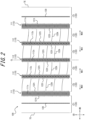
- Figure 2 is a plan view schematically illustrating a developed view of the tread surface 100 of the tire 1 in Figure 1 .
- the interior of each groove, depressed inward in the tire radial direction from the tread surface 100, is indicated by dot hatches.
- the "developed view of tread surface 100" refers to a planar view of the tread surface with the tread surface 100 expanded on a flat surface.
- the positional relationship and dimensions of each element of the tire 1 shall be measured in a "reference condition".
- the “reference condition” refers to the condition in which the tire 1 is assembled on the rim, filled with the prescribed internal pressure described above, and unloaded.
- the dimensions of the grooves, sipes, and other elements in the tread surface 100 shall be measured in the developed view of the tread surface 100.
- a plurality of main grooves 110 are provided on the tread surface 100.
- Each of the main grooves 110 extends continuously along the tire circumferential direction.
- the plurality of main grooves 110 include a pair of outermost main grooves 111 located at the outermost side in the tire width direction. This pair of outermost main grooves 111 are located on both sides of the tire equatorial plane CL.
- the plurality of main grooves 110 may include one or more (three in the embodiments of Figures 1 and 2 ) center main grooves 112 between the pair of outermost main grooves 111, or may include only one pair of outermost main grooves 111.
- the groove width of the main groove 110 is suitably 6 mm or more, more suitably 7 mm or more, and even more suitably 8 mm or more.
- the groove width of the main groove 110 is suitably 12 mm or less, and more suitably 10 mm or less.
- the groove depth of the main groove 110 is suitably 6 mm or more, more suitably 7 mm or more, and even more suitably 8 mm or more.
- the groove depth of the main groove 110 is suitably 12 mm or less, and more suitably 10 mm or less.
- the "groove” is defined as the one having a groove width of 1.3 mm or more at the tread surface 100 in the above reference condition.
- the groove includes the main groove 110 and an auxiliary groove 130.
- the groove width of the groove is suitably 1.5 mm or more.
- the "groove width” is the distance between a pair of groove walls facing each other, measured perpendicular to the extending direction of the groove, and may be constant or variable in the tire radial direction.
- the "groove” is preferably configured so that when the tire is mounted on the rim, filled with the prescribed internal pressure, and subjected to the maximum load, the pair of groove walls opposing each other do not come into contact with each other when the load is directly applied.
- a “sipe” is defined as the one having a sipe width of less than 1.3 mm at the tread surface 100 in the above reference condition.
- the sipe includes one-end-open sipes 121t and 122t, and two-end-open sipes 122k.
- the sipe width is suitably 1.0 mm or less, and more suitably 0.8 mm or less.
- the "sipe width” is the distance between a pair of sipe walls facing each other, measured perpendicular to the extending direction of the sipe.
- the "sipe” is suitably configured so that when the tire 1 is mounted on the rim, filled with the prescribed internal pressure, and subjected to the maximum load, the pair of opposing sipe walls contact each other at least in part when the load is directly applied.
- the tread surface 100 is provided with a plurality (six in this embodiment) of land portions 120, defined by a plurality (five in this embodiment) of main grooves 110 and a pair of ground contact edges TE.
- These plurality of land portions 120 include a pair of shoulder land portions 121, which are defined between the pair of outermost main grooves 111 and a pair of ground contact edges TE.
- these plurality of land portions 120 further include one or more (four in this embodiment) center land portions 122, which are defined between the plurality of main grooves 110.
- the shoulder land portion 121 is provided with the auxiliary groove 130.
- the auxiliary groove 130 is suitably provided in each shoulder land portion 121, as illustrated in Figures 1 and 2 , however, may be provided in only one of the shoulder land portions 121.
- the auxiliary groove 130 has a narrower groove width than the main groove 110 and extends along the tire circumferential direction.
- the auxiliary groove 130 suitably extends in a straight line.
- auxiliary groove 130 an outermost end in tire width direction 6bg of the one or more circumferential belt layers 6b, the shoulder land portion 121, etc., unless otherwise noted, it is assumed that the configuration of the tire 1 when viewed one half of the tire 1 with respect to the tire equatorial plane CL will be described.
- the tire 1 suitably has a similar configuration when viewed from the other half of the tire 1 with respect to the tire equatorial plane CL.
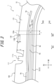
- Figure 3 is an enlarged view of a portion illustrated in Figure 1 .
- the outer end in the tire width direction 6be of at least one (one in the embodiment in Figure 1 and 3 ) circumferential belt layer 6b of the one or more circumferential belt layers 6b is located within the tire widthwise region corresponding to the shoulder land portion 121 (i.e., on the outer side in the tire width direction than the outermost main groove 111 and on the inner side in the tire width direction than the ground contact edge TE).
- each circumferential belt layer 6b is suitably located within the tire widthwise region corresponding to the shoulder land portion 121 (i.e., on the outer side in the tire width direction than the outermost main groove 111 and on the inner side in the tire width direction than the ground contact edge TE).
- the outer end in the tire width direction of at least one (one in the embodiment in Figure 1 and 3 ) intersecting belt layer 6a of the plurality of intersecting belt layers 6a is suitably located within the tire widthwise region corresponding to the shoulder land portion 121 (i.e., on the outer side in the tire width direction than the outermost main groove 111 and on the inner side in the tire width direction than the ground contact edge TE).
- the groove wall 130a located on the outer side in the tire width direction (hereinafter referred to as "outer groove wall 130a") is positioned on the inner side in the tire width direction than the outermost end in the tire width direction 6bg of the one or more circumferential belt layers 6b included in the belt 6.
- the "outermost end in the tire width direction 6bg of the one or more circumferential belt layers 6b" refers to the outermost end in the tire width direction 6be of the outer ends in the tire width direction 6be of each circumferential belt layer 6b.
- the belt 6 has a plurality of intersecting belt layers 6a and the one or more circumferential belt layers 6b, and the intersecting belt cords 6ac of the intersecting belt layer 6a have a low angle (20° to 45° with respect to the tire width direction) ( Figure 1 ).
- the dashed line in the graph schematically indicates the tension acting on the belt of a tire for one conventional reference example, which has a belt with a small intersecting angle between the belt cords of a plurality of belt layers.
- the dashed line in the graph in Figure 8 there are few or no tension steps in belts of such conventional tire, and the tension decreases smoothly from the tire equatorial plane CL to the outer side in the tire width direction.
- the auxiliary groove 130 is provided in the shoulder land portion 121, on the tread surface 100, as described above.
- the tread rubber 7 in the vicinity of the outer groove wall 130a of the auxiliary groove 130 is compressed by the load, and this causes the phenomenon H2 to bulge and deform the tread rubber 7 inward in the tire width direction (hereinafter referred to as "inward crushing").
- the outer groove wall 130a of the auxiliary groove 130 may be positioned at the same tire widthwise position as the outermost end in the tire width direction 6bg of the one or more circumferential belt layers 6b included in the belt 6.
- the position of the inward crushing H2 due to the outer groove wall 130a of the auxiliary groove 130 more firmly overlaps the position of the outward crushing H1 due to the outermost end in the tire width direction 6bg of the one or more circumferential belt layers 6b, therefore, the outward crushing H1 can be more effectively offset.
- the uneven wear resistance performance can be further improved.
- the outer groove wall 130a of the auxiliary groove 130 is positioned on the outer side in the tire width direction than the outermost end in the tire width direction 6bg of the one or more circumferential belt layers 6b included in the belt 6, when a load is applied to the tire 1, outward crushing H3 will occur also on the tread rubber 7 near the inner groove wall 130b of the auxiliary groove 130, in the vicinity of the outward crushing H1 due to the outermost end in the tire width direction 6bg of the one or more circumferential belt layers 6b. Therefore, the outward crashing H1 and H3 will be increased, which may worsen uneven wear in the shoulder land portion 121. This is especially true when the inner groove wall 130b of the auxiliary groove 130 is positioned at the same tire widthwise position as the outermost end in the tire width direction 6bg of the one or more circumferential belt layers 6b included in the belt 6.
- the outer groove wall 130a of the auxiliary groove 130 when designing the tire 1, it is suitable to set the outer groove wall 130a of the auxiliary groove 130 at a predetermined position on the inner side in the tire width direction than the outermost end in the tire width direction 6bg of the one or more circumferential belt layers 6b. Since there may be slight variations in the tire 1 that is actually manufactured, the relationship between the outer groove wall 130a of the auxiliary groove 130 and the outermost end in the tire width direction 6bg of the one or more circumferential belt layers 6b may deviate slightly from the expected one.
- the tire widthwise distance L from the outer groove wall 130a of the auxiliary groove 130 to the outermost end in the tire width direction 6bg of the one or more circumferential belt layers 6b is suitably 5% or less of the width W of the one or more circumferential belt layers 6b ( Figure 1 ).
- This tire widthwise distance L may be 0% of the width W as in the embodiment of Figure 6 , or may be more than 0% of the width W as in the embodiment of Figure 3 .
- width W of one or more circumferential belt layers 6b refers to the distance in the tire width direction between the outermost end in the tire width direction 6bg on both sides in the tire width direction of the one or more circumferential belt layers 6b ( Figure 3 ).
- the tire widthwise distance L from the outer groove wall 130a of the auxiliary groove 130 to the outermost end in the tire width direction 6bg of the one or more circumferential belt layers 6b is suitably less than or equal to twice of both amplitudes B of the wavy shape formed by the circumferential belt cords 6bc ( Figure 4 ).
- This tire widthwise distance L may be zero times the both amplitudes B, as in the embodiment illustrated in Figure 6 , or it may be more than zero times the both amplitudes B, as in the embodiment illustrated Figure 3 .
- the tire widthwise distance L from the outer groove wall 130a of the auxiliary groove 130 to the outermost end in the tire width direction 6bg of the one or more circumferential belt layers 6b is suitably 5mm or less.
- This tire widthwise distance L may be 0 mm as in the embodiment illustrated in Figure 6 , or may be more than 0 mm as in the embodiment illustrated Figure 3 .
- This configuration is particularly suitable when the tire 1 is a heavy-duty pneumatic tire (e.g., a truck and bus pneumatic tire).
- a heavy-duty pneumatic tire e.g., a truck and bus pneumatic tire.
- the outer groove wall 130a of the auxiliary groove 130 may be positioned on the inner side in the tire width direction than each of the outer ends 6be in the tire width direction of the one or more circumferential belt layers 6b.
- the groove depth D of the auxiliary groove 130 ( Figure 3 ) is suitably 10% or more of the groove depth E of the outermost main groove 111 ( Figure 3 ). This allows for a more robust effect of the inward crushing H2 due to the outer groove wall 130a of the auxiliary groove 130, further improving uneven wear resistance performance.
- the groove depth D of the auxiliary groove 130 is suitably smaller than the groove depth E of the outermost main groove 111, for example, 30% or less of the groove depth E of the outermost main groove 111. This prevents a reduction in rigidity.
- the auxiliary groove 130 can be made to disappear after the auxiliary groove 130 has achieved the desired effect to suppress uneven wear (for example, a wear rate of about 20%).
- the groove depth of the grooves shall be measured along the direction perpendicular to the tread surface 100.
- the groove depth of the main groove 110 shall refer to the groove depth of the main groove 110 when the protrusions 111s and 112s are considered absent, in other words, the distance, from the opening surface of the main groove 110 at the tread surface 100, to the inner end of the protrusions 111s and 112s in the tire radial direction.
- the groove width of the auxiliary groove 130 is suitably at least 10% of the groove width of the outermost main groove 111. This allows for a more robust effect of inward crushing H2 due to the outer groove wall 130a of the auxiliary groove 130, further improving uneven wear resistance performance.
- the groove width of the auxiliary groove is suitably 1.5mm or more, and more suitably 1.8mm or more.
- the groove width of the auxiliary groove 130 is suitably 20% or less of the groove width of the outermost main groove 111. This prevents a reduction in rigidity.
- the groove width of the auxiliary groove 130 is suitably 2.5 mm or less, and more suitably 2.2 mm or less.
- the number of belt layers 6a to 6c included in the belt 6 (the number of layers in the tire radial direction, and five in the embodiment of Figure 1 .) is suitably four or more, and more suitably five or more.
- the number of the circumferential belt layers 6b included in the belt 6 (two in the embodiment of Figure 1 ) is suitably two or more.
- the tension step near the outermost end in the tire width direction 6bg of the one or more circumferential belt layers 6b, as described above, is particularly large, so the effect on suppressing the uneven wear of the auxiliary groove 130 is particularly advantageous.
- each of the belt layers 6a to 6c included in the belt 6 suitably has the thickness of 1.3 mm or more, respectively.
- tire 1 is a heavy-duty pneumatic tire (e.g., a truck and bus pneumatic tire).
- the tread pattern on the tread surface 100 may be arbitrary, except that the auxiliary groove 130 is provided in the shoulder land portion 121 which is defined between the outermost main groove 111 and the ground contact edge TE.
- each shoulder land portion 121 is provided with a plurality of one-end-open sipes 121t in addition to the auxiliary groove 130.
- Each of the plurality of one-end-open sipes 121t opens at one end into the outermost main groove 111, extends outwardly in the tire width direction, and terminates at the other end inside the shoulder land portion 121 before reaching the auxiliary groove 130.
- the plurality of one-end-open sipes 121t are spaced from each other along the tire circumferential direction.
- Each shoulder land portion 121 is not provided with any grooves or sipes other than the auxiliary groove 130 and a plurality of one-end-open sipes 121t.
- each shoulder land portion 121 is suitably configured as a rib, not divided in the tire circumferential direction by a groove(s) extending along the tire width direction.
- the outward crushing H1 ( Figure 5 ) due to the outermost edge in the tire width direction 6bg of the one or more circumferential belt layers 6b described above is more likely to occur significantly, so the effect on suppressing the uneven wear due to the auxiliary grooves is particularly advantageous.
- each shoulder land portion 121 may be configured as a block row, divided in the tire circumferential direction by a groove(s) extending along the width direction groove.
- each center land portion 122 is provided with a plurality of one-end-open sipes 122t and a plurality of both-end-open sipes 122k, respectively.
- a plurality of one-end-open sipes 122t spaced from each other along the tire circumferential direction, open into each of the pair of main grooves 110 that define the center land portion 122.
- Each of the plurality of one-end-open sipes 122t opens at one end into one of the pair of main grooves 110 that define the center land portion 122, extends in the tire width direction, and terminates at the other end within the center land portion 122.
- each of the plurality of both-end-open sipes 122k extends along the tire width direction and opens at both ends into each of the pair of main grooves 110 that define the center land portion 122.
- the plurality of both-end-open sipes 122k are spaced from each other along the tire circumferential direction.
- Each center land portion 122 is not provided with any grooves or sipes other than the plurality of one-end-open sipes 122t and the plurality of both-end-open sipes 122k.
- each center land portion 122 is suitably configured as a rib, not divided in the tire circumferential direction by a groove(s) extending along the tire width direction.
- the outward crushing H1 ( Figure 5 ) due to the outermost edge in the tire width direction 6bg of the one or more circumferential belt layers 6b described above is more likely to occur significantly, so the effect on suppressing the uneven wear due to the auxiliary grooves is particularly advantageous.
- each center land portion 122 may be configured as a block row, divided in the tire circumferential direction by a groove(s) extending along the width direction groove.
- each outermost main groove 111 and each center main groove 112 have protrusions 111s and 112s, respectively, on their groove bottoms that protrude outward in the tire radial direction. As illustrated in Figure 1 , the outer ends of these projections 111s and 112s in the tire radial direction are located on the inner side than the tread surface 100 in the tire radial direction.
- each outermost main groove 111 may not have the protrusions 111s on its groove bottom surface.
- each center main groove 112 may not have the protrusions 112s on its groove bottom surface.
- the tire of the present disclosure can be used for any type of pneumatic tire, but can suitably be used for heavy-duty pneumatic tires, and even more suitably for truck and bus pneumatic tires.
Landscapes
- Engineering & Computer Science (AREA)
- Mechanical Engineering (AREA)
- Tires In General (AREA)
Abstract
Description
- This disclosure relates to a tire.
- This application claims priority based on
Japanese Patent Application No. 2021-202728 filed in Japan on December 14, 2021 - There are conventional tires with an intersecting belt layer and a circumferential belt layer (e.g., PTL 1).
- PTL 1:
JP 2012-071665 A - However, in the conventional tires as described above, there is room for improvement in terms of uneven wear resistance performance.
- It is an object of this disclosure to provide a tire that can improve uneven wear resistance performance.
- A tire comprising a belt and a tread surface, wherein
- the belt has:
- a plurality of intersecting belt layers, each containing intersecting belt cords extending in a direction that intersects each other between layers; and
- one or more circumferential belt layers, each containing circumferential belt cords extending along the tire circumferential direction,
- the intersecting belt cords have an angle of 20° to 45° with respect to the tire width direction,
- the tread surface is provided with:
- a plurality of main grooves, each extending along the tire circumferential direction;
- a shoulder land portion defined between an outermost main groove, that is located on the outermost side in the tire width direction among the plurality of main grooves, and a ground contact edge; and
- an auxiliary groove provided in the shoulder land portion, having a narrower width groove than the main grooves and extending along the tire circumferential direction, and
- an outer groove wall located on the outer side in the tire width direction of a pair of groove walls in the auxiliary groove is positioned either at the same tire widthwise position as an outermost end in the tire width direction of the one or more circumferential belt layers, or on the inner side in the tire width direction than the outermost end in the tire width direction of the one or more circumferential belt layers.
- According to the present disclosure, it is possible to provide a tire that can improve uneven wear resistance performance.
- In the accompanying drawings:
-
FIG. 1 is a cross-sectional view in the tire width direction, schematically illustrating a tire according to one embodiment of this disclosure; -
FIG. 2 is a plan view schematically illustrating a developed view of the tread surface of the tire inFigure 1 ; -
FIG. 3 is a cross-sectional view in the tire width direction, illustrating an enlarged portion of the tire inFigure 1 ; -
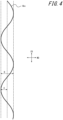
FIG. 4 is an explanatory drawing for explaining an example of a circumferential belt cord that can be suitably applied to tires according to any embodiments of the present disclosure; -
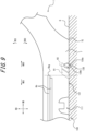
FIG. 5 is an explanatory drawing for explaining the behavior of the tire inFigure 1 under load; -
FIG. 6 is a drawing corresponding toFigure 3 and is a cross-sectional view in the tire width direction, illustrating an enlarged portion of a tire of another embodiment of this disclosure; -
FIG. 7 is an explanatory drawing for explaining the behavior of the tire inFigure 6 under load; -
FIG. 8 is an explanatory drawing for explaining the tension acting on the belts of the tire in the embodiment inFigure 1 and the tire according to one reference example, respectively; and -
FIG. 9 is an explanatory drawing for explaining the behavior of the tire according to another reference example under load. - The tire of the present disclosure can be used for any type of pneumatic tires, but can suitably be used for heavy-duty pneumatic tires, and even more suitably for truck and bus pneumatic tires.
- The following is an illustrative description of an embodiment of the tire according to this disclosure, with reference to the drawings.
- The following is an illustrative description of an embodiment of the tire according to the present disclosure, with reference to the drawings.
- In each figure, common components and parts are marked with the same reference numerals. In each figure, the tire width direction, the outer side in the tire width direction, and the inner side in the tire width direction are indicated by the signs "WD", "WDO", and "WDI", respectively; the tire radial direction, the outer side in the tire radial direction, and the inner side in the tire radial direction are indicated by the signs "RD", "RDO", and "RDI" respectively; and the tire circumferential direction is indicated by the sign "CD".
-
Figure 1 is a drawing for explaining atire 1 according to an embodiment of the present disclosure.Figure 1 is a cross-sectional view in the tire width direction, schematically illustrating thetire 1 according to one embodiment of this disclosure. - The
tire 1 of the embodiment inFigure 1 is configured as a heavy-duty pneumatic tire, more specifically, a truck and bus pneumatic tire. However, thetire 1 according to any embodiment of this disclosure may be configured as any type of tire. - As illustrated in
Figure 1 , thetire 1 comprises atread portion 1a, a pair ofsidewall portions 1b extending inward in the tire radial direction from both ends of thetread portion 1a in the tire width direction, and a pair ofbead portions 1c provided at the inner end in the tire radial direction of eachsidewall portion 1b. Thebead portion 1c is configured to contact a rim on the inner side in the tire radial direction and on the outer side in the tire width direction when thetire 1 is mounted on the rim. - The
tire 1 also comprises a pair ofbead cores 4a, a pair ofbead fillers 4b, acarcass 5, abelt 6, atread rubber 7,side rubbers 8, and aninner liner 9. - Each of the
bead cores 4a is embedded in thecorresponding bead portion 1c. Thebead core 4a comprises a plurality of bead wires whose surroundings are covered with rubber. The bead wires are suitably composed of metal (e.g. steel). The bead wires can, for example, be formed of monofilaments or stranded wires. - Each of the
bead fillers 4b is located on the outer side in the tire radial direction relative to thecorresponding bead core 4a. Thebead filler 4b tapers toward the outer side in the tire radial direction. Thebead filler 4b is composed of rubber, for example. - In general, the bead fillers are sometimes referred to as the "stiffeners".
- The
carcass 5 straddles between the pair ofbead cores 4a and extends in a toroidal shape. Thecarcass 5 consists of one ormore carcass plies 5a (one ply in the example inFigure 1 ). Eachcarcass ply 5a includes one or more carcass cords and coating rubber covering the carcass cords. The carcass cords can be formed of monofilaments or stranded wires. - The carcass cords 5c are suitably composed of metal (e.g., steel).
- The
carcass 5 suitably has a radial structure, but may also have a bias structure. - The
side rubber 8 is located in thesidewall portion 1b. Theside rubber 8 constitutes the outer surface of thesidewall portion 1b in the tire width direction. Theside rubber 8 is located on the outer side in the tire width direction than thecarcass 5. Theside rubber 8 is located on the outer side in the tire width direction than thebead filler 4b. Theside rubber 8 is formed integrally with thetread rubber 7. - The
inner liner 9 is arranged on the tire inner side of thecarcass 5, e.g., may be laminated to the tire inner side of thecarcass 5. Theinner liner 9 is made of butyl rubber with low air permeability, for example. The butyl rubber includes, for example, butyl rubber and its derivative, halogenated butyl rubber. Theinner liner 9 is not limited to butyl rubber, but can be made of other rubber compositions, resins, or elastomers. - As illustrated in
Figure 1 , thebelt 6 is arranged on the outer side in the tire radial direction relative to the crown of thecarcass 5. Thebelt 6 has a plurality ofbelt layers 6a to 6c (five layers in the embodiment ofFigure 1 ,). Thebelt 6 has, at least, a plurality of intersecting belt layers 6a and one or morecircumferential belt layers 6b. - The plurality of intersecting
belt layers 6a (two layers in the embodiment ofFigure 1 ) each contains intersecting belt cords 6ac extending in a direction that intersects each other between layers, and an intersecting belt coating rubber 6ar covering the intersecting belt cords 6ac. The intersecting belt cords 6ac are so-called low-angle belt cords with a small angle with respect to the tire width direction. Specifically, the intersecting belt cords 6ac have an angle of 20° to 45°with respect to the tire width direction. - The intersecting belt cords 6ac can be formed of monofilaments or twisted wires. The intersecting belt cords 6ac are suitably composed of metal (e.g., steel), however, may also be composed of organic fibers made of polyester, nylon, rayon, aramid, etc.
- The one or more
circumferential belt layers 6b (two layers in the embodiment ofFigure 1 ) each contains circumferential belt cords 6bc extending along the tire circumferential direction, and a circumferential belt coating rubber 6br covering the circumferential belt cords 6bc. - Regarding the circumferential belt cords 6bc, "extending along the tire circumferential direction" is not limited to the case extending parallel to the tire circumferential direction, but also includes the case extending in a direction greater than 0° and 5° or less with respect to the tire circumferential direction. Note, that when the circumferential belt cords 6bc have a wavy shape as described below (
Figure 4 ), the extending direction of the circumferential belt cords 6bc refers to the extending direction of the amplitude centerline of the wavy shape formed by the circumferential belt cord 6bc. - The circumferential belt cords 6bc can be formed of monofilaments or twisted wires. The circumferential belt cords 6bc are suitably composed of metal (e.g., steel), however, may also be composed of organic fibers made of polyester, nylon, rayon, aramid, etc.
- As illustrated in
Figure 4 , the circumferential belt cords 6bc are suitably so-called wavy cords having a wavy shape. In this case, the circumferential belt cords 6bc extend along the tire circumferential direction while amplifying in the tire width direction following the wavy shape. Here, the term "wavy shape" in this document is not limited to a wavy shape consisting of smooth curves as illustrated inFigure 4 , but also includes a wavy shape consisting of broken lines. The circumferential belt cords 6bc are habituated (molded) into a wavy shape. - In general, the crown portion of tire is always subjected to tensile input in the tire circumferential direction due to internal pressure during use, and tends to be distorted by circumferential elongation due to creep from use. Therefore, by making the circumferential belt cords 6bc in wavy shape, separation can be effectively prevented without increasing the weight of the
tire 1. This is especially true when thetire 1 is a heavy-duty pneumatic tire (e.g., a truck and bus pneumatic tire). - Both amplitudes B of the wavy shape formed by the circumferential belt cords 6bc are suitably 1.5 to 2.5mm, for example. Here, the "both amplitudes B of the wavy shape formed by the circumferential belt cords 6bc" is twice the single amplitude (amplitude) A of the wavy shape (
Figure 4 ). - However, instead of being in a wavy shape, the circumferential belt cords 6bc may extend in a straight line along the tire circumferential direction.
- As illustrated in
Figure 1 , the one or morecircumferential belt layers 6b are suitably positioned on the inner side in the tire radial direction than the plurality of intersectingbelt layers 6a. This makes it easier to maintain the shape of the tire when the tire is filled with internal pressure. - However, the positional relationship between the circumferential belt layers 6b and the intersecting
belt layers 6a is arbitrary; for example, one or morecircumferential belt layers 6b may be positioned on the outer side in the tire radial direction than the plurality of intersectingbelt layers 6a. - As illustrated in
Figure 1 , at least one of the plurality of intersectingbelt layers 6a (one layer in the embodiment ofFigure 1 ) suitably has a wider width (tire widthwise length) than eachcircumferential belt layer 6b. Thereby, uneven wear can be suppressed. - In addition to the one or more circumferential belt layers 6b and the plurality of intersecting
belt layers 6a, thebelt 6 may have one or moreother belt layers 6c (one layer in the embodiment ofFigure 1 ). Theother belt layers 6c may be positioned on the inner side in the tire radial direction than the one or more circumferential belt layers 6b and the plurality of intersecting belt layers 6a as illustrated inFigure 1 , may be positioned between the circumferential belt layers 6b and the intersectingbelt layers 6a, and/or may be positioned on the outer side in the tire radial direction than the one or more circumferential belt layers 6b and the plurality of intersectingbelt layers 6a. In the embodiment ofFigure 1 , there is noother belt layers 6c interposed between the one or more circumferential belt layers 6b and the plurality of intersectingbelt layers 6a. - The
other belt layer 6c may be, for example, aninclined belt layer 6c. Theinclined belt layer 6c includes inclined belt cords 6cc extending in an extending direction inclined to the tire circumferential direction, and an inclined belt coating rubber 6cr covering the inclined belt cords 6cc. - The inclined belt cords 6cc can be formed of monofilaments or twisted wires. The inclined belt cords 6cc are suitably composed of metal (e.g., steel), however, may also be composed of organic fibers made of polyester, nylon, rayon, aramid, etc.
- The
tread rubber 7 is located in thetread portion 1a, on the outer side of thebelt 6 in the tire radial direction. Thetread rubber 7 constitutes thetread surface 100, which is the outer surface of thetread portion 1a in the tire radial direction. A tread pattern is formed on thetread surface 100. - As used herein, the term "tread surface (100)" means the outer surface around the entire circumference of the tire that is in contact with the road surface when the tire is assembled on a rim, filled with prescribed internal pressure, and rolled under a maximum load.
- As used herein, the term "the ground contact edge (TE)" means the edge in the tire width direction of the tread surface (100).
- As used herein, the term "ground contact width" means the tire widthwise distance between a pair of ground contact edges of the tread surface (100).
- As used herein, the term "rim" refers to the standard rim in the applicable size (Measuring Rim in ETRTO's STANDARDS MANUAL and Design Rim in TRA's YEAR BOOK) as described or as may be described in the future in the industrial standard, which is valid for the region in which the tire is produced and used, such as JATMA YEAR BOOK of JATMA (Japan Automobile Tyre Manufacturers Association) in Japan, STANDARDS MANUAL of ETRTO (The European Tyre and Rim Technical Organization) in Europe, and YEAR BOOK of TRA (The Tire and Rim Association, Inc.) in the United States (That is, the "rim" includes current sizes as well as future sizes to be listed in the aforementioned industrial standards. An example of the "size as described in the future" could be the sizes listed as "FUTURE DEVELOPMENTS" in the ETRTO 2013 edition.). For sizes not listed in these industrial standards, the term "rim" refers to a rim with a width corresponding to the bead width of the tire.
- As used herein, the "prescribed internal pressure" refers to the air pressure (maximum air pressure) corresponding to the maximum load capacity of a single wheel in the applicable size and ply rating, as described in the aforementioned JATMA YEAR BOOK and other industrial standards. In the case that the size is not listed in the aforementioned industrial standards, the "prescribed internal pressure" refers to the air pressure (maximum air pressure) corresponding to the maximum load capacity specified for each vehicle in which the tire is mounted.
- The term "maximum load" shall mean the load corresponding to the above maximum load capacity.
- Note, that the air as used herein can be replaced by inert gas such as nitrogen gas or other inert gas.
-
Figure 2 is a plan view schematically illustrating a developed view of thetread surface 100 of thetire 1 inFigure 1 . InFigure 2 , the interior of each groove, depressed inward in the tire radial direction from thetread surface 100, is indicated by dot hatches. - Herein, the "developed view of
tread surface 100" refers to a planar view of the tread surface with thetread surface 100 expanded on a flat surface. - In this document, unless otherwise noted, the positional relationship and dimensions of each element of the
tire 1 shall be measured in a "reference condition". The "reference condition" refers to the condition in which thetire 1 is assembled on the rim, filled with the prescribed internal pressure described above, and unloaded. The dimensions of the grooves, sipes, and other elements in thetread surface 100 shall be measured in the developed view of thetread surface 100. - As illustrated in
Figures 1 to 2 , in this embodiment, a plurality ofmain grooves 110 are provided on thetread surface 100. Each of themain grooves 110 extends continuously along the tire circumferential direction. The plurality ofmain grooves 110 include a pair of outermostmain grooves 111 located at the outermost side in the tire width direction. This pair of outermostmain grooves 111 are located on both sides of the tire equatorial plane CL. As in the embodiments ofFigures 1 and2 , the plurality ofmain grooves 110 may include one or more (three in the embodiments ofFigures 1 and2 ) centermain grooves 112 between the pair of outermostmain grooves 111, or may include only one pair of outermostmain grooves 111. - The groove width of the
main groove 110 is suitably 6 mm or more, more suitably 7 mm or more, and even more suitably 8 mm or more. The groove width of themain groove 110 is suitably 12 mm or less, and more suitably 10 mm or less. - The groove depth of the
main groove 110 is suitably 6 mm or more, more suitably 7 mm or more, and even more suitably 8 mm or more. The groove depth of themain groove 110 is suitably 12 mm or less, and more suitably 10 mm or less. - In this document, the "groove" is defined as the one having a groove width of 1.3 mm or more at the
tread surface 100 in the above reference condition. In this embodiment, the groove includes themain groove 110 and anauxiliary groove 130. The groove width of the groove is suitably 1.5 mm or more. The "groove width" is the distance between a pair of groove walls facing each other, measured perpendicular to the extending direction of the groove, and may be constant or variable in the tire radial direction. The "groove" is preferably configured so that when the tire is mounted on the rim, filled with the prescribed internal pressure, and subjected to the maximum load, the pair of groove walls opposing each other do not come into contact with each other when the load is directly applied. - In this document, a "sipe" is defined as the one having a sipe width of less than 1.3 mm at the
tread surface 100 in the above reference condition. In this embodiment, the sipe includes one-end-open sipes open sipes 122k. The sipe width is suitably 1.0 mm or less, and more suitably 0.8 mm or less. The "sipe width" is the distance between a pair of sipe walls facing each other, measured perpendicular to the extending direction of the sipe. The "sipe" is suitably configured so that when thetire 1 is mounted on the rim, filled with the prescribed internal pressure, and subjected to the maximum load, the pair of opposing sipe walls contact each other at least in part when the load is directly applied. - As illustrated in
Figures 1 and2 , thetread surface 100 is provided with a plurality (six in this embodiment) ofland portions 120, defined by a plurality (five in this embodiment) ofmain grooves 110 and a pair of ground contact edges TE. These plurality ofland portions 120 include a pair ofshoulder land portions 121, which are defined between the pair of outermostmain grooves 111 and a pair of ground contact edges TE. In addition, these plurality ofland portions 120 further include one or more (four in this embodiment)center land portions 122, which are defined between the plurality ofmain grooves 110. - The
shoulder land portion 121 is provided with theauxiliary groove 130. Theauxiliary groove 130 is suitably provided in eachshoulder land portion 121, as illustrated inFigures 1 and2 , however, may be provided in only one of theshoulder land portions 121. Theauxiliary groove 130 has a narrower groove width than themain groove 110 and extends along the tire circumferential direction. - As illustrated in
Figure 2 , theauxiliary groove 130 suitably extends in a straight line. - In the following, when describing the
auxiliary groove 130, an outermost end in tire width direction 6bg of the one or morecircumferential belt layers 6b, theshoulder land portion 121, etc., unless otherwise noted, it is assumed that the configuration of thetire 1 when viewed one half of thetire 1 with respect to the tire equatorial plane CL will be described. Thetire 1 suitably has a similar configuration when viewed from the other half of thetire 1 with respect to the tire equatorial plane CL. -
Figure 3 is an enlarged view of a portion illustrated inFigure 1 . As illustrated inFigures 1 and3 , the outer end in the tire width direction 6be of at least one (one in the embodiment inFigure 1 and3 )circumferential belt layer 6b of the one or morecircumferential belt layers 6b is located within the tire widthwise region corresponding to the shoulder land portion 121 (i.e., on the outer side in the tire width direction than the outermostmain groove 111 and on the inner side in the tire width direction than the ground contact edge TE). - As illustrated in
Figures 1 and3 , the outer end in the tire width direction 6be of eachcircumferential belt layer 6b is suitably located within the tire widthwise region corresponding to the shoulder land portion 121 (i.e., on the outer side in the tire width direction than the outermostmain groove 111 and on the inner side in the tire width direction than the ground contact edge TE). - As illustrated in
Figures 1 and3 , the outer end in the tire width direction of at least one (one in the embodiment inFigure 1 and3 ) intersectingbelt layer 6a of the plurality of intersectingbelt layers 6a is suitably located within the tire widthwise region corresponding to the shoulder land portion 121 (i.e., on the outer side in the tire width direction than the outermostmain groove 111 and on the inner side in the tire width direction than the ground contact edge TE). - As illustrated in
Figure 3 , of the pair ofgroove walls auxiliary groove 130, thegroove wall 130a located on the outer side in the tire width direction (hereinafter referred to as "outer groove wall 130a") is positioned on the inner side in the tire width direction than the outermost end in the tire width direction 6bg of the one or morecircumferential belt layers 6b included in thebelt 6. - Here, the "outermost end in the tire width direction 6bg of the one or more
circumferential belt layers 6b" refers to the outermost end in the tire width direction 6be of the outer ends in the tire width direction 6be of eachcircumferential belt layer 6b. - Here, the effects of this embodiment will be explained.
- First, in this embodiment, as described above, the
belt 6 has a plurality of intersecting belt layers 6a and the one or morecircumferential belt layers 6b, and the intersecting belt cords 6ac of the intersectingbelt layer 6a have a low angle (20° to 45° with respect to the tire width direction) (Figure 1 ). Due to this configuration of thebelt 6, in which the intersecting angles between the belt cords of the plurality of belt layers are large (specifically, the intersecting angle between the circumferential belt cords 6bc of thecircumferential belt layer 6b and the intersecting belt cords 6ac of the intersectingbelt layer 6a is large), as indicated by the solid line in the graph inFigure 8 , a large tension step occurs in thebelt 6 at the vicinity of the outermost end in the tire width direction 6bg of the one or morecircumferential belt layers 6b. InFigure 8 , the solid line in the graph schematically indicates the tension acting on thebelt 6 of thetire 1 in this embodiment. InFigure 8 , the dashed line in the graph schematically indicates the tension acting on the belt of a tire for one conventional reference example, which has a belt with a small intersecting angle between the belt cords of a plurality of belt layers. As can be seen from the dashed line in the graph inFigure 8 , there are few or no tension steps in belts of such conventional tire, and the tension decreases smoothly from the tire equatorial plane CL to the outer side in the tire width direction. As illustrated inFigure 5 , when a load is applied to thetire 1 of this embodiment, thetread rubber 7 between the outermost end in the tire width direction 6bg of one or more circumferential belt layers 6b and the road surface G is compressed by the load, and the above tension step causes the phenomenon H1 to bulge and deform thetread rubber 7 between them outward in the tire width direction (hereinafter referred to as "outward crushing"). This outward crushing H1 may lead to uneven wear in theshoulder land portion 121. This outward crushing H1 is particularly noticeable when thetire 1 is a heavy-duty pneumatic tire (e.g., a truck and bus pneumatic tire). - Therefore, in this embodiment, the
auxiliary groove 130 is provided in theshoulder land portion 121, on thetread surface 100, as described above. By providing theauxiliary groove 130, as illustrated inFigure 5 , when a load is applied to thetire 1, thetread rubber 7 in the vicinity of theouter groove wall 130a of theauxiliary groove 130 is compressed by the load, and this causes the phenomenon H2 to bulge and deform thetread rubber 7 inward in the tire width direction (hereinafter referred to as "inward crushing"). As mentioned above, since theouter groove wall 130a of theauxiliary groove 130 is positioned on the inner side in the tire width direction than the outermost end in the tire width direction 6bg of the one or morecircumferential belt layers 6b, the inward crushing H2 due to theouter groove wall 130a of theauxiliary groove 130 can offset the outward crushing H1 due to the outermost end in the tire width direction 6bg of the one or morecircumferential belt layers 6b. Therefore, uneven wear at theshoulder land portion 121 can be suppressed, which in turn improves uneven wear resistance performance. - Not limited to the above-mentioned embodiments, as well as the other embodiment illustrated in
Figure 6 , theouter groove wall 130a of theauxiliary groove 130 may be positioned at the same tire widthwise position as the outermost end in the tire width direction 6bg of the one or morecircumferential belt layers 6b included in thebelt 6. In this case, as illustrated inFigure 7 , when a load is applied to thetire 1, the position of the inward crushing H2 due to theouter groove wall 130a of theauxiliary groove 130 more firmly overlaps the position of the outward crushing H1 due to the outermost end in the tire width direction 6bg of the one or morecircumferential belt layers 6b, therefore, the outward crushing H1 can be more effectively offset. Thus, the uneven wear resistance performance can be further improved. - If, as in the other reference example illustrated in
Figure 9 , theouter groove wall 130a of theauxiliary groove 130 is positioned on the outer side in the tire width direction than the outermost end in the tire width direction 6bg of the one or morecircumferential belt layers 6b included in thebelt 6, when a load is applied to thetire 1, outward crushing H3 will occur also on thetread rubber 7 near theinner groove wall 130b of theauxiliary groove 130, in the vicinity of the outward crushing H1 due to the outermost end in the tire width direction 6bg of the one or morecircumferential belt layers 6b. Therefore, the outward crashing H1 and H3 will be increased, which may worsen uneven wear in theshoulder land portion 121. This is especially true when theinner groove wall 130b of theauxiliary groove 130 is positioned at the same tire widthwise position as the outermost end in the tire width direction 6bg of the one or morecircumferential belt layers 6b included in thebelt 6. - Note, that when designing the
tire 1, it is suitable to set theouter groove wall 130a of theauxiliary groove 130 at a predetermined position on the inner side in the tire width direction than the outermost end in the tire width direction 6bg of the one or morecircumferential belt layers 6b. Since there may be slight variations in thetire 1 that is actually manufactured, the relationship between theouter groove wall 130a of theauxiliary groove 130 and the outermost end in the tire width direction 6bg of the one or morecircumferential belt layers 6b may deviate slightly from the expected one. By pre-setting the position of theouter groove wall 130a of theauxiliary groove 130 at a predetermined position that is on the inner side in the tire width direction than the outermost end in the tire width direction 6bg of the one or morecircumferential belt layers 6b, even if such a slight deviation occurs during manufacturing, it can be more reliably avoided that theouter groove wall 130a of theauxiliary groove 130 is positioned, in the manufacturedtire 1, on the outer side in the tire width direction than the outermost end in the tire width direction 6bg of the one or morecircumferential belt layers 6b included in the belt 6 (Figure 9 ). - In each of the embodiments described herein, the tire widthwise distance L from the
outer groove wall 130a of theauxiliary groove 130 to the outermost end in the tire width direction 6bg of the one or morecircumferential belt layers 6b is suitably 5% or less of the width W of the one or morecircumferential belt layers 6b (Figure 1 ). This tire widthwise distance L may be 0% of the width W as in the embodiment ofFigure 6 , or may be more than 0% of the width W as in the embodiment ofFigure 3 . - This allows the inward crushing H2 due to the
outer groove wall 130a of theauxiliary groove 130 to be closer to the outward crushing H1 due to the outermost end in the tire width direction 6bg of the one or morecircumferential belt layers 6b, which can more effectively offset the outward crushing H1. Thus, the uneven wear resistance performance can be further improved (Figures 5 and7 ). - Here, the "width W of one or more
circumferential belt layers 6b" (Figure 1 ) refers to the distance in the tire width direction between the outermost end in the tire width direction 6bg on both sides in the tire width direction of the one or morecircumferential belt layers 6b (Figure 3 ). - In each of the embodiments described herein, when the circumferential belt cords 6bc have a wavy shape as described above (
Figure 4 ), the tire widthwise distance L from theouter groove wall 130a of theauxiliary groove 130 to the outermost end in the tire width direction 6bg of the one or morecircumferential belt layers 6b is suitably less than or equal to twice of both amplitudes B of the wavy shape formed by the circumferential belt cords 6bc (Figure 4 ). This tire widthwise distance L may be zero times the both amplitudes B, as in the embodiment illustrated inFigure 6 , or it may be more than zero times the both amplitudes B, as in the embodiment illustratedFigure 3 . - This allows the inward crushing H2 due to the
outer groove wall 130a of theauxiliary groove 130 to be closer to the outward crushing H1 due to the outermost end in the tire width direction 6bg of the one or morecircumferential belt layers 6b, which can more effectively offset the outward crushing H1. Thus, the uneven wear resistance performance can be further improved (Figures 5 and7 ). - In each of the embodiments described herein, the tire widthwise distance L from the
outer groove wall 130a of theauxiliary groove 130 to the outermost end in the tire width direction 6bg of the one or morecircumferential belt layers 6b is suitably 5mm or less. This tire widthwise distance L may be 0 mm as in the embodiment illustrated inFigure 6 , or may be more than 0 mm as in the embodiment illustratedFigure 3 . - This allows the inward crushing H2 due to the
outer groove wall 130a of theauxiliary groove 130 to be closer to the outward crushing H1 due to the outermost end in the tire width direction 6bg of the one or morecircumferential belt layers 6b, which can more effectively offset the outward crushing H1. Thus, the uneven wear resistance performance can be further improved (Figures 5 and7 ). - This configuration is particularly suitable when the
tire 1 is a heavy-duty pneumatic tire (e.g., a truck and bus pneumatic tire). - The
outer groove wall 130a of theauxiliary groove 130 may be positioned on the inner side in the tire width direction than each of the outer ends 6be in the tire width direction of the one or morecircumferential belt layers 6b. - In each of the embodiments described herein, the groove depth D of the auxiliary groove 130 (
Figure 3 ) is suitably 10% or more of the groove depth E of the outermost main groove 111 (Figure 3 ). This allows for a more robust effect of the inward crushing H2 due to theouter groove wall 130a of theauxiliary groove 130, further improving uneven wear resistance performance. - In addition, the groove depth D of the
auxiliary groove 130 is suitably smaller than the groove depth E of the outermostmain groove 111, for example, 30% or less of the groove depth E of the outermostmain groove 111. This prevents a reduction in rigidity. - Furthermore, by setting the groove depth D of the
auxiliary groove 130 to 10 to 30% of the groove depth E of the outermostmain groove 111, theauxiliary groove 130 can be made to disappear after theauxiliary groove 130 has achieved the desired effect to suppress uneven wear (for example, a wear rate of about 20%). - Note, that the groove depth of the grooves (
main grooves 110 and auxiliary grooves 130) shall be measured along the direction perpendicular to thetread surface 100. In addition, when themain groove 110 hasprotrusions Figures 1 and2 , the groove depth of themain groove 110 shall refer to the groove depth of themain groove 110 when theprotrusions main groove 110 at thetread surface 100, to the inner end of theprotrusions - In each of the embodiments described herein, the groove width of the
auxiliary groove 130 is suitably at least 10% of the groove width of the outermostmain groove 111. This allows for a more robust effect of inward crushing H2 due to theouter groove wall 130a of theauxiliary groove 130, further improving uneven wear resistance performance. - From the same perspective, the groove width of the auxiliary groove is suitably 1.5mm or more, and more suitably 1.8mm or more.
- In addition, the groove width of the
auxiliary groove 130 is suitably 20% or less of the groove width of the outermostmain groove 111. This prevents a reduction in rigidity. - From the same perspective, the groove width of the
auxiliary groove 130 is suitably 2.5 mm or less, and more suitably 2.2 mm or less. - In each of the embodiments described herein, the number of
belt layers 6a to 6c included in the belt 6 (the number of layers in the tire radial direction, and five in the embodiment ofFigure 1 .) is suitably four or more, and more suitably five or more. - In addition, the number of the
circumferential belt layers 6b included in the belt 6 (two in the embodiment ofFigure 1 ) is suitably two or more. In this case, the tension step near the outermost end in the tire width direction 6bg of the one or morecircumferential belt layers 6b, as described above, is particularly large, so the effect on suppressing the uneven wear of theauxiliary groove 130 is particularly advantageous. - In addition, each of the belt layers 6a to 6c included in the
belt 6 suitably has the thickness of 1.3 mm or more, respectively. - These configurations are particularly suitable when the
tire 1 is a heavy-duty pneumatic tire (e.g., a truck and bus pneumatic tire). - Note, that in each of the embodiments described herein, with respect to the tread pattern provided on the
tread surface 100, as long as theauxiliary groove 130 is provided in theshoulder land portion 121 defined between the outermostmain groove 111 and the ground contact edge TE, the effect on suppressing the uneven wear by the above-mentionedauxiliary groove 130 can be obtained. Therefore, the tread pattern on thetread surface 100 may be arbitrary, except that theauxiliary groove 130 is provided in theshoulder land portion 121 which is defined between the outermostmain groove 111 and the ground contact edge TE. - In the embodiment of
Figure 2 , eachshoulder land portion 121 is provided with a plurality of one-end-open sipes 121t in addition to theauxiliary groove 130. Each of the plurality of one-end-open sipes 121t opens at one end into the outermostmain groove 111, extends outwardly in the tire width direction, and terminates at the other end inside theshoulder land portion 121 before reaching theauxiliary groove 130. In addition, the plurality of one-end-open sipes 121t are spaced from each other along the tire circumferential direction. Eachshoulder land portion 121 is not provided with any grooves or sipes other than theauxiliary groove 130 and a plurality of one-end-open sipes 121t. - As in the embodiment of
Figure 2 , eachshoulder land portion 121 is suitably configured as a rib, not divided in the tire circumferential direction by a groove(s) extending along the tire width direction. In this case, the outward crushing H1 (Figure 5 ) due to the outermost edge in the tire width direction 6bg of the one or morecircumferential belt layers 6b described above is more likely to occur significantly, so the effect on suppressing the uneven wear due to the auxiliary grooves is particularly advantageous. - However, each
shoulder land portion 121 may be configured as a block row, divided in the tire circumferential direction by a groove(s) extending along the width direction groove. - In the embodiment of
Figure 2 , eachcenter land portion 122 is provided with a plurality of one-end-open sipes 122t and a plurality of both-end-open sipes 122k, respectively. In eachcenter land portion 122, a plurality of one-end-open sipes 122t, spaced from each other along the tire circumferential direction, open into each of the pair ofmain grooves 110 that define thecenter land portion 122. Each of the plurality of one-end-open sipes 122t opens at one end into one of the pair ofmain grooves 110 that define thecenter land portion 122, extends in the tire width direction, and terminates at the other end within thecenter land portion 122. In addition, in eachcenter land portion 122, each of the plurality of both-end-open sipes 122k extends along the tire width direction and opens at both ends into each of the pair ofmain grooves 110 that define thecenter land portion 122. The plurality of both-end-open sipes 122k are spaced from each other along the tire circumferential direction. Eachcenter land portion 122 is not provided with any grooves or sipes other than the plurality of one-end-open sipes 122t and the plurality of both-end-open sipes 122k. - As in the embodiment of
Figure 2 , eachcenter land portion 122 is suitably configured as a rib, not divided in the tire circumferential direction by a groove(s) extending along the tire width direction. In this case, the outward crushing H1 (Figure 5 ) due to the outermost edge in the tire width direction 6bg of the one or morecircumferential belt layers 6b described above is more likely to occur significantly, so the effect on suppressing the uneven wear due to the auxiliary grooves is particularly advantageous. However, eachcenter land portion 122 may be configured as a block row, divided in the tire circumferential direction by a groove(s) extending along the width direction groove. - In the embodiment of
Figure 2 , each outermostmain groove 111 and each centermain groove 112 haveprotrusions Figure 1 , the outer ends of theseprojections tread surface 100 in the tire radial direction. - However, each outermost
main groove 111 may not have theprotrusions 111s on its groove bottom surface. Also, each centermain groove 112 may not have theprotrusions 112s on its groove bottom surface. - The tire of the present disclosure can be used for any type of pneumatic tire, but can suitably be used for heavy-duty pneumatic tires, and even more suitably for truck and bus pneumatic tires.
-
- 1
- Tire
- 1a
- Tread portion
- 1b
- Sidewall portion
- 1c
- Bead portion
- 4a
- Bead core
- 4b
- Bead filler
- 5
- Carcass
- 5a
- Carcass ply
- 6
- Belt
- 6a
- Intersecting belt layer (Belt layer)
- 6ac
- Intersecting belt cord
- 6ar
- Intersecting belt coating rubber
- 6b
- Circumferential belt layer (Belt layer)
- 6bc
- Circumferential belt cord
- 6br
- Circumferential belt coating rubber
- 6be
- Outer end in the tire width direction
- 6bg
- Outermost end in the tire width direction
- 6c
- Inclined belt layer (Belt layer)
- 6cc
- Inclined belt cord
- 6cr
- Inclined belt coating rubber
- 7
- Tread rubber
- 8
- Side rubber
- 9
- Inner liner
- 100
- Tread surface
- 110
- Main groove
- 111
- Outermost main groove
- 111s
- Protrusion
- 112
- Center main groove
- 112s
- Protrusion
- 120
- Land portion
- 121
- Shoulder land portion
- 121t
- One-end-open sipe
- 122
- Center land portion
- 122t
- One-end-open sipe
- 122k
- Both-ends-open sipe
- 130
- Auxiliary groove
- 130a
- Outer groove wall
- 130b
- Inner groove wall
- CL
- Tire equatorial plane
- TE
- Ground contact edge
- WD
- Tire width direction
- WDO
- Outer side in the tire width direction
- WDI
- Inner side in the tire width direction
- RD
- Tire radial direction
- RDO
- Outer side in the tire radial direction
- RDI
- Inner side in the tire radial direction
- CD
- Tire circumferential direction
- G
- Road surface
Claims (7)
- A tire comprising a belt and a tread surface, whereinthe belt has:a plurality of intersecting belt layers, each containing intersecting belt cords extending in a direction that intersects each other between layers; andone or more circumferential belt layers, each containing circumferential belt cords extending along the tire circumferential direction,the intersecting belt cords have an angle of 20° to 45° with respect to the tire width direction,the tread surface is provided with:a plurality of main grooves, each extending along the tire circumferential direction;a shoulder land portion defined between an outermost main groove, that is located on the outermost side in the tire width direction among the plurality of main grooves, and a ground contact edge; andan auxiliary groove provided in the shoulder land portion, having a narrower width groove than the main grooves and extending along the tire circumferential direction, andan outer groove wall located on the outer side in the tire width direction of a pair of groove walls in the auxiliary groove is positioned either at the same tire widthwise position as an outermost end in the tire width direction of the one or more circumferential belt layers, or on the inner side in the tire width direction than the outermost end in the tire width direction of the one or more circumferential belt layers.
- The tire according to claim 1, wherein tire widthwise distance L from the outer groove wall in the auxiliary groove to the outermost end in the tire width direction of the one or more circumferential belt layers is 5% or less of the width W of the one or more circumferential belt layers.
- The tire according to claim 1 or 2, wherein the circumferential belt cords have a wavy shape, and the tire widthwise distance L from the outer groove wall in the auxiliary groove to the outermost end in the tire width direction of the one or more circumferential belt layers is less than or equal to twice of both amplitudes B of the wavy shape formed by the circumferential belt cords.
- The tire according to any one of claims 1 to 3, wherein the tire widthwise distance L from the outer groove wall in the auxiliary groove to the outermost end in the tire width direction of the one or more circumferential belt layers is 5mm or less.
- The tire according to any one of claims 1 to 4, wherein the groove depth D of the auxiliary groove is 10 to 30% of the groove depth E of the outermost main groove.
- The tire according to any one of claims 1 to 5, wherein the outer groove wall in the auxiliary groove is positioned on the inner side in the tire width direction than the outer end in the tire width direction of each of the one or more circumferential belt layers.
- The tire according to any one of claims 1 to 6, wherein the one or more tire circumferential belt layers are positioned on the inner side in the tire radial direction than the plurality of intersecting belt layers.
Applications Claiming Priority (2)
| Application Number | Priority Date | Filing Date | Title |
|---|---|---|---|
| JP2021202728A JP7715620B2 (en) | 2021-12-14 | 2021-12-14 | tire |
| PCT/JP2022/020436 WO2023112353A1 (en) | 2021-12-14 | 2022-05-16 | Tire |
Publications (3)
| Publication Number | Publication Date |
|---|---|
| EP4450299A1 true EP4450299A1 (en) | 2024-10-23 |
| EP4450299A4 EP4450299A4 (en) | 2025-03-26 |
| EP4450299B1 EP4450299B1 (en) | 2026-04-08 |
Family
ID=86774241
Family Applications (1)
| Application Number | Title | Priority Date | Filing Date |
|---|---|---|---|
| EP22906890.3A Active EP4450299B1 (en) | 2021-12-14 | 2022-05-16 | Tire |
Country Status (5)
| Country | Link |
|---|---|
| US (1) | US20250170857A1 (en) |
| EP (1) | EP4450299B1 (en) |
| JP (1) | JP7715620B2 (en) |
| CN (1) | CN118354912A (en) |
| WO (1) | WO2023112353A1 (en) |
Families Citing this family (1)
| Publication number | Priority date | Publication date | Assignee | Title |
|---|---|---|---|---|
| JP2025104771A (en) | 2023-12-28 | 2025-07-10 | 住友ゴム工業株式会社 | tire |
Family Cites Families (13)
| Publication number | Priority date | Publication date | Assignee | Title |
|---|---|---|---|---|
| JP2001121919A (en) * | 1999-10-26 | 2001-05-08 | Bridgestone Corp | Pneumatic radial tire |
| JP4749128B2 (en) * | 2005-11-16 | 2011-08-17 | 株式会社ブリヂストン | Pneumatic tire |
| JP2008195360A (en) * | 2007-02-16 | 2008-08-28 | Sumitomo Rubber Ind Ltd | Pneumatic tire |
| JP5109823B2 (en) * | 2008-06-12 | 2012-12-26 | 横浜ゴム株式会社 | Pneumatic tire |
| JP4618385B2 (en) * | 2008-10-16 | 2011-01-26 | 横浜ゴム株式会社 | Pneumatic tire |
| US20100186860A1 (en) * | 2009-01-26 | 2010-07-29 | Francois Pierre Charles Gerard Georges | Tread for a radial medium truck tire |
| BR112012001846A2 (en) * | 2009-07-27 | 2017-05-16 | Bridgestone Corp | construction vehicle tire. |
| JP5149957B2 (en) * | 2010-12-14 | 2013-02-20 | 住友ゴム工業株式会社 | Pneumatic tire |
| DE112011105647B4 (en) * | 2011-09-22 | 2016-03-24 | The Yokohama Rubber Co., Ltd. | tire |
| JP6649850B2 (en) * | 2016-06-13 | 2020-02-19 | 株式会社ブリヂストン | Pneumatic tire |
| JP6993864B2 (en) * | 2017-12-20 | 2022-01-14 | Toyo Tire株式会社 | Pneumatic tires |
| JP7745572B2 (en) * | 2020-06-11 | 2025-09-29 | コンパニー ゼネラール デ エタブリッスマン ミシュラン | Low-noise tires |
| DE112022000337T5 (en) * | 2021-02-22 | 2023-09-14 | The Yokohama Rubber Co., Ltd. | Tires |
-
2021
- 2021-12-14 JP JP2021202728A patent/JP7715620B2/en active Active
-
2022
- 2022-05-16 WO PCT/JP2022/020436 patent/WO2023112353A1/en not_active Ceased
- 2022-05-16 US US18/711,611 patent/US20250170857A1/en not_active Abandoned
- 2022-05-16 EP EP22906890.3A patent/EP4450299B1/en active Active
- 2022-05-16 CN CN202280080658.0A patent/CN118354912A/en active Pending
Also Published As
| Publication number | Publication date |
|---|---|
| US20250170857A1 (en) | 2025-05-29 |
| JP7715620B2 (en) | 2025-07-30 |
| WO2023112353A1 (en) | 2023-06-22 |
| CN118354912A (en) | 2024-07-16 |
| EP4450299B1 (en) | 2026-04-08 |
| EP4450299A4 (en) | 2025-03-26 |
| JP2023088085A (en) | 2023-06-26 |
Similar Documents
| Publication | Publication Date | Title |
|---|---|---|
| JP5041104B1 (en) | Pneumatic tire | |
| US12344040B2 (en) | Pneumatic tire | |
| US11001104B2 (en) | Run-flat radial tire | |
| EP2889159B1 (en) | Heavy duty tire | |
| US20170028782A1 (en) | Pneumatic tire | |
| US9987883B2 (en) | Pneumatic tire | |
| EP2979900B1 (en) | Heavy load pneumatic tire | |
| US8002007B2 (en) | Pneumatic radial tire for heavy loads | |
| CN105682940B (en) | Tire | |
| US10391816B2 (en) | Pneumatic tire | |
| EP4147884B1 (en) | Tire | |
| EP4389465B1 (en) | Heavy duty tire | |
| US9950570B2 (en) | Pneumatic tire | |
| EP4450299B1 (en) | Tire | |
| US20250042203A1 (en) | Tire | |
| US20170028779A1 (en) | Pneumatic tire | |
| EP4438335B1 (en) | Tire | |
| CN110475678B (en) | Pneumatic tires | |
| US12472779B2 (en) | Tire | |
| CN120569299A (en) | Passenger car tyre | |
| US20170028787A1 (en) | Pneumatic tire and method for manufacturing thereof | |
| US20260109177A1 (en) | Tire | |
| EP4714677A1 (en) | Pneumatic tire | |
| EP4711155A1 (en) | Heavy duty tire | |
| JP2025102225A (en) | Pneumatic tire |
Legal Events
| Date | Code | Title | Description |
|---|---|---|---|
| STAA | Information on the status of an ep patent application or granted ep patent |
Free format text: STATUS: THE INTERNATIONAL PUBLICATION HAS BEEN MADE |
|
| PUAI | Public reference made under article 153(3) epc to a published international application that has entered the european phase |
Free format text: ORIGINAL CODE: 0009012 |
|
| STAA | Information on the status of an ep patent application or granted ep patent |
Free format text: STATUS: REQUEST FOR EXAMINATION WAS MADE |
|
| 17P | Request for examination filed |
Effective date: 20240524 |
|
| AK | Designated contracting states |
Kind code of ref document: A1 Designated state(s): AL AT BE BG CH CY CZ DE DK EE ES FI FR GB GR HR HU IE IS IT LI LT LU LV MC MK MT NL NO PL PT RO RS SE SI SK SM TR |
|
| REG | Reference to a national code |
Ref country code: DE Ref legal event code: R079 Free format text: PREVIOUS MAIN CLASS: B60C0009180000 Ipc: B60C0009200000 Ref country code: DE Ref legal event code: R079 Ref document number: 602022034345 Country of ref document: DE Free format text: PREVIOUS MAIN CLASS: B60C0009180000 Ipc: B60C0009200000 |
|
| A4 | Supplementary search report drawn up and despatched |
Effective date: 20250224 |
|
| DAV | Request for validation of the european patent (deleted) | ||
| DAX | Request for extension of the european patent (deleted) | ||
| RIC1 | Information provided on ipc code assigned before grant |
Ipc: B60C 11/13 20060101ALN20250218BHEP Ipc: B60C 11/12 20060101ALN20250218BHEP Ipc: B60C 9/28 20060101ALI20250218BHEP Ipc: B60C 11/03 20060101ALI20250218BHEP Ipc: B60C 9/22 20060101ALI20250218BHEP Ipc: B60C 9/20 20060101AFI20250218BHEP |
|
| GRAP | Despatch of communication of intention to grant a patent |
Free format text: ORIGINAL CODE: EPIDOSNIGR1 |
|
| STAA | Information on the status of an ep patent application or granted ep patent |
Free format text: STATUS: GRANT OF PATENT IS INTENDED |
|
| RIC1 | Information provided on ipc code assigned before grant |
Ipc: B60C 9/20 20060101AFI20251128BHEP Ipc: B60C 9/22 20060101ALI20251128BHEP Ipc: B60C 11/03 20060101ALI20251128BHEP Ipc: B60C 9/28 20060101ALI20251128BHEP Ipc: B60C 11/12 20060101ALN20251128BHEP Ipc: B60C 11/13 20060101ALN20251128BHEP |
|
| INTG | Intention to grant announced |
Effective date: 20260102 |
|
| GRAS | Grant fee paid |
Free format text: ORIGINAL CODE: EPIDOSNIGR3 |
|
| GRAA | (expected) grant |
Free format text: ORIGINAL CODE: 0009210 |
|
| STAA | Information on the status of an ep patent application or granted ep patent |
Free format text: STATUS: THE PATENT HAS BEEN GRANTED |
|
| AK | Designated contracting states |
Kind code of ref document: B1 Designated state(s): AL AT BE BG CH CY CZ DE DK EE ES FI FR GB GR HR HU IE IS IT LI LT LU LV MC MK MT NL NO PL PT RO RS SE SI SK SM TR |
|
| REG | Reference to a national code |
Ref country code: CH Ref legal event code: F10 Free format text: ST27 STATUS EVENT CODE: U-0-0-F10-F00 (AS PROVIDED BY THE NATIONAL OFFICE) Effective date: 20260408 Ref country code: GB Ref legal event code: FG4D |
|
| REG | Reference to a national code |
Ref country code: DE Ref legal event code: R096 Ref document number: 602022034345 Country of ref document: DE |
|
| P01 | Opt-out of the competence of the unified patent court (upc) registered |
Free format text: CASE NUMBER: UPC_APP_0010585_4450299/2026 Effective date: 20260320 |
|
| REG | Reference to a national code |
Ref country code: IE Ref legal event code: FG4D |
|
| PGFP | Annual fee paid to national office [announced via postgrant information from national office to epo] |
Ref country code: DE Payment date: 20260522 Year of fee payment: 5 |
|
| PGFP | Annual fee paid to national office [announced via postgrant information from national office to epo] |
Ref country code: AT Payment date: 20260714 Year of fee payment: 5 |
|
| PGFP | Annual fee paid to national office [announced via postgrant information from national office to epo] |
Ref country code: FR Payment date: 20260602 Year of fee payment: 5 |