EP4450228A1 - Pulse tool - Google Patents
Pulse tool Download PDFInfo
- Publication number
- EP4450228A1 EP4450228A1 EP24169199.7A EP24169199A EP4450228A1 EP 4450228 A1 EP4450228 A1 EP 4450228A1 EP 24169199 A EP24169199 A EP 24169199A EP 4450228 A1 EP4450228 A1 EP 4450228A1
- Authority
- EP
- European Patent Office
- Prior art keywords
- electric pulse
- mass
- tool according
- pulse tool
- output shaft
- Prior art date
- Legal status (The legal status is an assumption and is not a legal conclusion. Google has not performed a legal analysis and makes no representation as to the accuracy of the status listed.)
- Pending
Links
Images


Classifications
-
- B—PERFORMING OPERATIONS; TRANSPORTING
- B25—HAND TOOLS; PORTABLE POWER-DRIVEN TOOLS; MANIPULATORS
- B25B—TOOLS OR BENCH DEVICES NOT OTHERWISE PROVIDED FOR, FOR FASTENING, CONNECTING, DISENGAGING, OR HOLDING
- B25B21/00—Portable power-driven screw or nut setting or loosening tools; Attachments for drilling apparatus serving the same purpose
- B25B21/02—Portable power-driven screw or nut setting or loosening tools; Attachments for drilling apparatus serving the same purpose with means for imparting impact to screwdriver blade or nut socket
- B25B21/026—Impact clutches
-
- B—PERFORMING OPERATIONS; TRANSPORTING
- B25—HAND TOOLS; PORTABLE POWER-DRIVEN TOOLS; MANIPULATORS
- B25B—TOOLS OR BENCH DEVICES NOT OTHERWISE PROVIDED FOR, FOR FASTENING, CONNECTING, DISENGAGING, OR HOLDING
- B25B21/00—Portable power-driven screw or nut setting or loosening tools; Attachments for drilling apparatus serving the same purpose
-
- B—PERFORMING OPERATIONS; TRANSPORTING
- B25—HAND TOOLS; PORTABLE POWER-DRIVEN TOOLS; MANIPULATORS
- B25B—TOOLS OR BENCH DEVICES NOT OTHERWISE PROVIDED FOR, FOR FASTENING, CONNECTING, DISENGAGING, OR HOLDING
- B25B21/00—Portable power-driven screw or nut setting or loosening tools; Attachments for drilling apparatus serving the same purpose
- B25B21/02—Portable power-driven screw or nut setting or loosening tools; Attachments for drilling apparatus serving the same purpose with means for imparting impact to screwdriver blade or nut socket
-
- B—PERFORMING OPERATIONS; TRANSPORTING
- B25—HAND TOOLS; PORTABLE POWER-DRIVEN TOOLS; MANIPULATORS
- B25B—TOOLS OR BENCH DEVICES NOT OTHERWISE PROVIDED FOR, FOR FASTENING, CONNECTING, DISENGAGING, OR HOLDING
- B25B23/00—Details of, or accessories for, spanners, wrenches, screwdrivers
-
- B—PERFORMING OPERATIONS; TRANSPORTING
- B25—HAND TOOLS; PORTABLE POWER-DRIVEN TOOLS; MANIPULATORS
- B25B—TOOLS OR BENCH DEVICES NOT OTHERWISE PROVIDED FOR, FOR FASTENING, CONNECTING, DISENGAGING, OR HOLDING
- B25B27/00—Hand tools, specially adapted for fitting together or separating parts or objects whether or not involving some deformation, not otherwise provided for
- B25B27/14—Hand tools, specially adapted for fitting together or separating parts or objects whether or not involving some deformation, not otherwise provided for for assembling objects other than by press fit or detaching same
Definitions
- the present invention generally relates to power tools for tightening of threaded fasteners, more particularly to electric impulse type power tools.
- Pulse tool for tightening are known to be used in various industries.
- power wrenches of the impulse type comprising hydraulic pulse units are commonly used for continuous heavy production.
- torque is delivered intermittently to an output shaft by means of a hydraulic pulse generating unit.
- Pulse tool are known for having advantages such as operation at high speed and power without reaction forces.
- the hydraulic pulse generating unit of such tools is filled with oil.
- torque pulses may be delivered to the output shaft by means of a pulse generating mechanism dividing a fluid chamber into a low pressure side and a high pressure side, where fluid may flow between these sides during operation.
- Such flows of fluid are however often associated with losses, and hence have a large effect on the efficiency of the pulse tool.
- pulse tools i.e. the fact that they are based on the principle of a fast moving motor connecting to a slow moving tap, energy losses are inevitable.
- losses are also associated with the fact that, as pulse tool build up inertia by varying speed, losses are also due to the fact that the motor has to run at varying speeds and cannot remain at the speed where it is most efficient.
- an electric pulse tool comprising an electric motor drivingly connected to a flywheel unit and an output shaft, whereby the electric pulse tool is operative to rotate the flywheel unit, wherein the flywheel unit is arranged to intermittently transfer kinetic energy to the output shaft to provide a torque pulse to the output shaft, and wherein the moment of inertia of the flywheel unit is variable, such that the torque pulse may be provided by means of a forced decrease of moment of inertia of the flywheel unit.
- the impulse tool (or pulse tool, power wrench, power tool or tightening tool, these terms are used interchangeably throughout the present specification) provides an inventive solution to the concerns described above by means of a design where instead of (and/or in addition to) varying the speed of the flywheel unit, the inertia of the flywheel unit is varied to achieve the pulses.
- the inventor has realized that by means of a design where the inertia of the flywheel unit may be varied, the tool may operate at a (more or less) constant speed while delivering pulses, thereby mitigating or even avoiding losses associated with the conventional method of having a fast moving motor connecting intermittently to a slow moving tap.
- the motor may also operate continuously at a speed where the electrical motor operates at maximum efficiency thus both reducing losses and increasing efficiency of the motor as such.
- the referenced pulse tool may be a battery powered tool or a tool powered by cord.
- the pulse tool may further comprise a housing having a front end and a back end, wherein the output shaft may be arranged at the front end of the housing.
- the electric pulse tool further comprises means coupling, or connecting or operably connecting, the output shaft and the flywheel unit and arranged to effect the variable moment of inertia of the flywheel unit.
- These coupling- or connecting means may include a mechanical assembly.
- coupling, or connecting may be understood providing an operable connection or coupling there between.
- the variable moment of inertia is achieved by the means effecting a variable mass centre radius of the fly wheel unit.
- the flywheel unit comprises at least one radially movable mass element, wherein the variable mass centre radius is provided by means of the means, or assembly, effecting a radial movement of at least a portion of the at least one radially movable mass element.
- radial should be understood a radial direction with respect to the output shaft.
- the movable mass element, or a portion thereof and/or the mass center of the mass element may for example be effected to follow a path having a varying radius over a revolution of the fly wheel unit.
- the at least one radially movable mass element is arranged to intermittently transfer kinetic energy to the output shaft.
- This energy transfer may be achieved by the movable mass element selectively contacting and/or hitting the output shaft (or a portion thereof).
- the contact may in some embodiments be periodically achieved over a revolution of the mass element with respect to the output shaft.
- the flywheel unit comprises a rotatably arranged mass holder driven by the motor, wherein the at least one movable mass element is movably arranged on, or at least with respect to, the mass holder, wherein the means (i.e. the means effecting a variable mass centre radius of the fly wheel unit) comprises a cam element comprising a first cam profile provided co-rotating with the output shaft and wherein the first cam profile is arranged to effect a movement of the mass element, such that the moment of inertia of the flywheel unit varies.
- the first cam profile is arranged to force a movement radially inward of the at least one movable mass element, such that the mass centre radius of the flywheel unit is decreased, thereby creating forces that generates the torque pulse as the flywheel unit is compressed to a smaller radius during the pulse.
- the exact behavior of the mass element i.e. the way the mass center radius changes in order to vary the inertia, is determined by the cam shape and can hence be adapted based on the desired behavior.
- the means further comprises at least one cam following arm, or lever, attached to the at least one mass element at a first end, and arranged to follow the first cam profile at a second end.
- the path of the variable mass centre radius may be controlled by means of the design of the cam profile, and the interaction between and the arm and profile, thereby creating a desired behavior of the forces generating the torque pulse.
- the mass holder comprises a mass holder bracket driven by the motor, wherein the at least one movably arranged mass elements is movably arranged on, or at least with respect to, the mass holder bracket by means of a link arm.
- the link arm is rigidly attached to the mass element at a first end, and movably attached to the mass holder bracket at a second end.
- the link arm may for example be pivotally attached to the mass holder bracket and screwed to the mass element.
- the mass element is movably arranged with respect to the mass holder bracket by means of two link arms.
- the cam profile is located on the outside of the output shaft.
- the mass holder may be arranged to enclose, or cover, the cam profile.
- the cam profile is located on the inside of a ring shaped element coupled to the output shaft.
- the electric pulse tool further comprises a first and a second mass element.
- the electric pulse tool further comprises a first and a second cam element comprising a first and second cam profile respectively.
- a first and a second mass element may be attached to a respective first and second cam following arm, arranged to follow the first and a second cam profile respectively.
- the electric pulse tool may comprise n number of mass element and n number of cam elements, n being an integer number >2.
- the mass element has a curved outer shape and comprises a central opening.
- the power tool further comprises a possibly cylindrical pulse unit housing adapted to cover the flywheel unit and at least a portion of the output shaft, wherein the mass element may have a bent shape adapted to fit in the housing.
- the electric motor is adapted to drive the flywheel at a controlled speed, in some embodiments the electric motor is adapted to drive the flywheel at a constant speed.
- the electric pulse tool further comprises a sensor adapted to measure a rotational speed of the rotor.
- a pulse unit for an electric pulse tool comprising an output shaft and a flywheel unit, wherein the flywheel unit is arranged to be driven by the motor of the power tool to intermittently transfer kinetic energy to the output shaft to provide a torque pulse to the output shaft, and wherein the moment of inertia of the flywheel unit is variable, such that the torque pulse may be provided by means of a forced decrease of moment of inertia of the flywheel unit.
- Figure 1 shows an exemplary pulse tool 1 according to one embodiment, in this case a pistol type tool comprising a housing 100 having a front end 100a and a back end 100b, in which a motor 10 and a pulse generating unit or mechanism is arranged, and further having a square ended output shaft 30 extending at the front end of the housing.
- a pistol type tool comprising a housing 100 having a front end 100a and a back end 100b, in which a motor 10 and a pulse generating unit or mechanism is arranged, and further having a square ended output shaft 30 extending at the front end of the housing.
- the pulse generating mechanism comprises a flywheel unit 20 drivingly connected to the electric motor 10 such that the flywheel unit 20 may be rotated.
- the flywheel unit 20 is arranged to intermittently transfer kinetic energy to the output shaft 30 or in other words to provide torque pulses to the output shaft 30.
- the moment of inertia of the flywheel unit is variable. More particularly, the torque pulse may be provided by means of a forced decrease of the moment of inertia of said flywheel unit.
- the inertia is varied by means of a design comprising means operably connecting or coupling the output shaft 30 and the flywheel unit 20 allowing for a variable mass centre radius of the flywheel unit 20, thereby effecting the variable moment of inertia
- the illustrated flywheel unit 20 comprises a radially movable mass element 40 movably arranged on, or movably connected to, a mass holder bracket 21 driven by the motor 10.
- the means mentioned above comprises a cam element 50 having a first cam profile 51 provided on the output shaft 30.
- a cam following arm 60 is attached to the mass element at a first end, in the illustrated embodiment rigidly attached, and arranged to follow the first cam profile 51 at a second end hereby effecting a movement of the mass element varying the mass center radius, such that the moment of inertia of the flywheel unit varies.
- the flywheel unit will go through the following phases: When the mass element 40 is at its largest radius it travels at full speed and is ready to deliver a pulse. As the mass element is forced back towards the center of rotation, the output shaft 30 defining an axis of rotation, the mass element is hitting the cam turning towards the rotation center, this force against the cam is what creates the torque. The mass element then utilizes the speed for the next pulse as the mass element moves along the cam back to a large radius, while being accelerated by the motor 10. During the whole revolution, the speed of the motor 10 is substantially constant.
- Fig 3 schematically illustrates a second embodiment where the same effect as described above may be achieved, but where the cam profile 51, in the illustrated embodiment a first and second cam profile 51a, 51b, is instead provided on the inside of a ring shaped, or cylindrical element 70, coupled to the output shaft 30.
- the embodiment shown in fig. 3 further comprises a first and a second mass element 40a, 40b arranged to engage the first and a second cam element 51a,51b and hence the first and second cam profile respectively by means of a first and second cam follower arm 60a, 60b.
- the first and second mass element will be forced radially inward to deliver torque pulses to the output shaft while rotating at a substantially constant speed analogue to what has been described for the embodiment shown in fig. 2 .
- Fig. 4 shows yet another embodiment of a pulse generating mechanism according to the claimed principle, in cross section.
- the pulse generating mechanism comprises a flywheel unit 20 arranged to provide torque pulses to the output shaft 30 by means of a variable inertia of the flywheel unit.
- a variable mass centre radius of the flywheel unit 20 is achieved by a design incorporating two radially movable mass elements 40a, 40b movably arranged on a mass holder bracket 21, 22 driven by the motor 10.
- the mass elements are arranged on the bracket by means of two respective link arms 41 (i.e. a total of four link arms are provided).
- the link arms are pivotally attached to the mass holder bracket, and screwed to the respective mass elements.
- a respective cam following arm 60a, 60b (not shown) is attached to each mass element at a first end, and arranged to follow a first and a second cam profile 51a, 51b provided on the outer side of the output shaft 30 at a second end, to effect a movement of the mass element varying the mass center radius, such that the moment of inertia of the flywheel unit varies.
- the first and second cam profile in the illustrated embodiment have the same profile, and are arranged in a mirrored manner on the output shaft, the first and second mass element move synchronously and consequently provide pulses on the output shaft 30 simultaneously.
- each mass element in the illustrated embodiment has a slightly bent outer shape to fit in a cylindrical outer housing 80, and are arranged on opposite sides of the output shaft facing one another.
- each mass element comprises a central opening 44a, 44b through which the cam following arms may move.
- the cam following arm 41 travels along the cam shape to control the mass element traveling from full speed at its largest radius, to turning toward the rotation center to deliver the pulse and then travelling back along the long shape of the cam back to the larger radius.
Landscapes
- Engineering & Computer Science (AREA)
- Mechanical Engineering (AREA)
- Connection Of Motors, Electrical Generators, Mechanical Devices, And The Like (AREA)
- Details Of Spanners, Wrenches, And Screw Drivers And Accessories (AREA)
- Transmission Devices (AREA)
Abstract
Description
- The present invention generally relates to power tools for tightening of threaded fasteners, more particularly to electric impulse type power tools.
- Electrical power tools for tightening are known to be used in various industries. For example, power wrenches of the impulse type comprising hydraulic pulse units are commonly used for continuous heavy production. In such tools, torque is delivered intermittently to an output shaft by means of a hydraulic pulse generating unit. Pulse tool are known for having advantages such as operation at high speed and power without reaction forces.
- The hydraulic pulse generating unit of such tools is filled with oil. In such pulse tools, torque pulses may be delivered to the output shaft by means of a pulse generating mechanism dividing a fluid chamber into a low pressure side and a high pressure side, where fluid may flow between these sides during operation. Such flows of fluid are however often associated with losses, and hence have a large effect on the efficiency of the pulse tool.
- Further, due to the inherent nature of pulse tools, i.e. the fact that they are based on the principle of a fast moving motor connecting to a slow moving tap, energy losses are inevitable.
- For electric pulse tool, losses are also associated with the fact that, as pulse tool build up inertia by varying speed, losses are also due to the fact that the motor has to run at varying speeds and cannot remain at the speed where it is most efficient.
- Hence, there exists a need for improvement in the field of power tools where torque is delivered in pulses.
- Accordingly, it would be desirable to provide a more efficient pulse tool. In particular, it would be desirable to provide such an improved pulse tool able to operate at a speed where the motor operates at its most efficient. To better address one or more of these concerns an electric pulse tool according to the independent claim is provided. Preferred embodiments are defined in the dependent claims.
- According to a first aspect of the invention an electric pulse tool is provided, the tool comprising an electric motor drivingly connected to a flywheel unit and an output shaft, whereby the electric pulse tool is operative to rotate the flywheel unit, wherein the flywheel unit is arranged to intermittently transfer kinetic energy to the output shaft to provide a torque pulse to the output shaft, and wherein the moment of inertia of the flywheel unit is variable, such that the torque pulse may be provided by means of a forced decrease of moment of inertia of the flywheel unit.
- According to the first aspect, the impulse tool (or pulse tool, power wrench, power tool or tightening tool, these terms are used interchangeably throughout the present specification) provides an inventive solution to the concerns described above by means of a design where instead of (and/or in addition to) varying the speed of the flywheel unit, the inertia of the flywheel unit is varied to achieve the pulses.
- More particularly, the inventor has realized that by means of a design where the inertia of the flywheel unit may be varied, the tool may operate at a (more or less) constant speed while delivering pulses, thereby mitigating or even avoiding losses associated with the conventional method of having a fast moving motor connecting intermittently to a slow moving tap. The motor may also operate continuously at a speed where the electrical motor operates at maximum efficiency thus both reducing losses and increasing efficiency of the motor as such.
- The combination of operating at a high average speed and the ability to keep energy for the next pulse since there is no stops, makes the tool very efficient and fast, i.e. able to use a high pulse frequency as well as deliver high torque. Hence the efficiency of the power tool may be significantly improved.
- The referenced pulse tool may be a battery powered tool or a tool powered by cord. The pulse tool may further comprise a housing having a front end and a back end, wherein the output shaft may be arranged at the front end of the housing.
- According to one embodiment, the electric pulse tool further comprises means coupling, or connecting or operably connecting, the output shaft and the flywheel unit and arranged to effect the variable moment of inertia of the flywheel unit. These coupling- or connecting means may include a mechanical assembly. By coupling, or connecting, may be understood providing an operable connection or coupling there between. According to one embodiment, the variable moment of inertia is achieved by the means effecting a variable mass centre radius of the fly wheel unit.
- According to one embodiment, the flywheel unit comprises at least one radially movable mass element, wherein the variable mass centre radius is provided by means of the means, or assembly, effecting a radial movement of at least a portion of the at least one radially movable mass element. By radial should be understood a radial direction with respect to the output shaft. The movable mass element, or a portion thereof and/or the mass center of the mass element may for example be effected to follow a path having a varying radius over a revolution of the fly wheel unit.
- According to one embodiment, the at least one radially movable mass element is arranged to intermittently transfer kinetic energy to the output shaft.
- This energy transfer may be achieved by the movable mass element selectively contacting and/or hitting the output shaft (or a portion thereof). The contact may in some embodiments be periodically achieved over a revolution of the mass element with respect to the output shaft.
- According to one embodiment, the flywheel unit comprises a rotatably arranged mass holder driven by the motor, wherein the at least one movable mass element is movably arranged on, or at least with respect to, the mass holder, wherein the means (i.e. the means effecting a variable mass centre radius of the fly wheel unit) comprises a cam element comprising a first cam profile provided co-rotating with the output shaft and wherein the first cam profile is arranged to effect a movement of the mass element, such that the moment of inertia of the flywheel unit varies.
- According to one embodiment, the first cam profile is arranged to force a movement radially inward of the at least one movable mass element, such that the mass centre radius of the flywheel unit is decreased, thereby creating forces that generates the torque pulse as the flywheel unit is compressed to a smaller radius during the pulse. The exact behavior of the mass element, i.e. the way the mass center radius changes in order to vary the inertia, is determined by the cam shape and can hence be adapted based on the desired behavior.
- According to one embodiment, the means further comprises at least one cam following arm, or lever, attached to the at least one mass element at a first end, and arranged to follow the first cam profile at a second end. Hereby, the path of the variable mass centre radius may be controlled by means of the design of the cam profile, and the interaction between and the arm and profile, thereby creating a desired behavior of the forces generating the torque pulse.
- According to one embodiment, the mass holder comprises a mass holder bracket driven by the motor, wherein the at least one movably arranged mass elements is movably arranged on, or at least with respect to, the mass holder bracket by means of a link arm. In one embodiment, the link arm is rigidly attached to the mass element at a first end, and movably attached to the mass holder bracket at a second end. The link arm may for example be pivotally attached to the mass holder bracket and screwed to the mass element. In one embodiment, the mass element is movably arranged with respect to the mass holder bracket by means of two link arms.
- According to one embodiment, the cam profile is located on the outside of the output shaft. In such an embodiment, the mass holder may be arranged to enclose, or cover, the cam profile.
- According to one embodiment, the cam profile is located on the inside of a ring shaped element coupled to the output shaft.
- According to one embodiment, the electric pulse tool further comprises a first and a second mass element. According to one embodiment, the electric pulse tool further comprises a first and a second cam element comprising a first and second cam profile respectively. In some embodiments, hence, a first and a second mass element may be attached to a respective first and second cam following arm, arranged to follow the first and a second cam profile respectively. In some embodiments the electric pulse tool may comprise n number of mass element and n number of cam elements, n being an integer number >2.
- According to one embodiment, the mass element has a curved outer shape and comprises a central opening. In some embodiments, the power tool further comprises a possibly cylindrical pulse unit housing adapted to cover the flywheel unit and at least a portion of the output shaft, wherein the mass element may have a bent shape adapted to fit in the housing.
- According to one embodiment, the electric motor is adapted to drive the flywheel at a controlled speed, in some embodiments the electric motor is adapted to drive the flywheel at a constant speed. According to one embodiment, the electric pulse tool further comprises a sensor adapted to measure a rotational speed of the rotor.
- According to a second aspect of the present invention a pulse unit for an electric pulse tool is provided, the pulse unit comprising an output shaft and a flywheel unit, wherein the flywheel unit is arranged to be driven by the motor of the power tool to intermittently transfer kinetic energy to the output shaft to provide a torque pulse to the output shaft, and wherein the moment of inertia of the flywheel unit is variable, such that the torque pulse may be provided by means of a forced decrease of moment of inertia of the flywheel unit. Objectives, advantages and features of the unit conceivable within the scope of the second aspect of the invention are readily understood by the foregoing discussion referring to the first aspect of the invention.
- Further objectives of, features of and advantages of the present invention will become apparent when studying the following detailed disclosure, the drawings and the appended claims. Those skilled in the art realize that different features of the present invention can be combined to create embodiments other than those described in the following.
- The invention will be described in the following illustrative and non-limiting detailed description of exemplary embodiments, with reference to the appended drawing, on which
-
Figure 1 is a side view of an exemplary power tool according to one embodiment. -
Figure 2 is a schematic illustration of some of the components of a pulse tool according to one embodiment. -
Figure 3 is a schematic illustration of some of the components of a pulse tool according to one embodiment. -
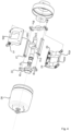
Figure 4 is an exploded view of an electric pulse tool according to one embodiment. - All figures are schematic, not necessarily to scale and generally only show parts which are necessary in order to elucidate the invention, wherein other parts may be omitted or merely suggested.
-
Figure 1 shows an exemplary pulse tool 1 according to one embodiment, in this case a pistol type tool comprising a housing 100 having afront end 100a and aback end 100b, in which amotor 10 and a pulse generating unit or mechanism is arranged, and further having a square endedoutput shaft 30 extending at the front end of the housing. - The pulse generating mechanism, schematically illustrated in
fig. 2 , comprises a flywheel unit 20 drivingly connected to theelectric motor 10 such that the flywheel unit 20 may be rotated. The flywheel unit 20 is arranged to intermittently transfer kinetic energy to theoutput shaft 30 or in other words to provide torque pulses to theoutput shaft 30. - In order to provide torque pulses, the moment of inertia of the flywheel unit is variable. More particularly, the torque pulse may be provided by means of a forced decrease of the moment of inertia of said flywheel unit.
- In the illustrated embodiment, the inertia is varied by means of a design comprising means operably connecting or coupling the
output shaft 30 and the flywheel unit 20 allowing for a variable mass centre radius of the flywheel unit 20, thereby effecting the variable moment of inertia In order to achieve this effect, the illustrated flywheel unit 20 comprises a radially movablemass element 40 movably arranged on, or movably connected to, amass holder bracket 21 driven by themotor 10. - The means mentioned above comprises a cam element 50 having a first cam profile 51 provided on the
output shaft 30. Acam following arm 60 is attached to the mass element at a first end, in the illustrated embodiment rigidly attached, and arranged to follow the first cam profile 51 at a second end hereby effecting a movement of the mass element varying the mass center radius, such that the moment of inertia of the flywheel unit varies. - During one revolution the flywheel unit will go through the following phases:
When themass element 40 is at its largest radius it travels at full speed and is ready to deliver a pulse. As the mass element is forced back towards the center of rotation, theoutput shaft 30 defining an axis of rotation, the mass element is hitting the cam turning towards the rotation center, this force against the cam is what creates the torque. The mass element then utilizes the speed for the next pulse as the mass element moves along the cam back to a large radius, while being accelerated by themotor 10. During the whole revolution, the speed of themotor 10 is substantially constant. -
Fig 3 schematically illustrates a second embodiment where the same effect as described above may be achieved, but where the cam profile 51, in the illustrated embodiment a first andsecond cam profile cylindrical element 70, coupled to theoutput shaft 30. - The embodiment shown in
fig. 3 further comprises a first and a secondmass element second cam element cam follower arm fig. 2 . -
Fig. 4 shows yet another embodiment of a pulse generating mechanism according to the claimed principle, in cross section. - Similarly to the embodiments shown in
figures 2 and3 , the pulse generating mechanism, offig. 4 , comprises a flywheel unit 20 arranged to provide torque pulses to theoutput shaft 30 by means of a variable inertia of the flywheel unit. - In the illustrated embodiment, a variable mass centre radius of the flywheel unit 20 is achieved by a design incorporating two radially movable
mass elements mass holder bracket motor 10. The mass elements are arranged on the bracket by means of two respective link arms 41 (i.e. a total of four link arms are provided). The link arms are pivotally attached to the mass holder bracket, and screwed to the respective mass elements. - A respective
cam following arm second cam profile output shaft 30 at a second end, to effect a movement of the mass element varying the mass center radius, such that the moment of inertia of the flywheel unit varies. As the first and second cam profile in the illustrated embodiment have the same profile, and are arranged in a mirrored manner on the output shaft, the first and second mass element move synchronously and consequently provide pulses on theoutput shaft 30 simultaneously. - The mass elements in the illustrated embodiment have a slightly bent outer shape to fit in a cylindrical
outer housing 80, and are arranged on opposite sides of the output shaft facing one another. In order to allow for the movement of the arm of the opposite mass element, each mass element comprises acentral opening - As described above with reference to the embodiment of
fig. 1 , in operation as the motor rotates the mass holder thecam following arm 41 travels along the cam shape to control the mass element traveling from full speed at its largest radius, to turning toward the rotation center to deliver the pulse and then travelling back along the long shape of the cam back to the larger radius. - While the invention has been illustrated and described in detail in the drawings and foregoing description, such illustration and description are to be considered illustrative or exemplary and not restrictive; the invention is not limited to the disclosed embodiment. The skilled person understands that many modifications, variations and alterations are conceivable within the scope as defined in the appended claims. Additionally, variations to the disclosed embodiments can be understood and effected by those skilled in the art in practicing the claimed invention, form a study of the drawings, the disclosure and the appended claims. In the claims, the word "comprising" does not exclude other elements or steps and the indefinite article "a" or "an" does not exclude a plurality. The mere fact that certain measures are recited in mutually different dependent claims does not indicate that a combination of these measures cannot be used to advantage. Any reference signs in the claims should not be construed as limiting the scope of the claims.
Claims (15)
- An electric pulse tool comprising:an electric motor (10) drivingly connected to a flywheel unit (20); andan output shaft (30),whereby the electric pulse tool is operative to rotate the flywheel unit (20),wherein the flywheel unit is arranged to intermittently transfer kinetic energy to the output shaft (30) to provide a torque pulse to the output shaft,and wherein the moment of inertia of the flywheel unit is variable, such that said torque pulse may be provided by means of a forced decrease of moment of inertia of said flywheel unit.
- Electric pulse tool according to claim 1, further comprising means operably connecting said output shaft and said flywheel unit and arranged to effect said variable moment of inertia of said flywheel unit.
- Electric pulse tool according to claim 2, wherein said variable moment of inertia is achieved by said means effecting a variable mass centre radius of the fly wheel unit.
- Electric pulse tool according to claim 3, wherein the flywheel unit comprises at least one radially movable mass element and wherein the variable mass centre radius is provided by means of said means effecting a radial movement of at least a portion of said at least one radially movable mass element (40).
- Electric pulse tool according to claim 4, wherein the at least one radially movable mass element is arranged to intermittently transfer kinetic energy to the output shaft.
- Electric pulse tool according to any one of the preceding claims 3-5, wherein the flywheel unit comprises a rotatably arranged mass holder (3, 1) driven by the motor,wherein said at least one movable mass element is movably arranged on said mass holder,wherein said means comprises a cam element (50) comprising a first cam profile provided co-rotating with the output shaft,and wherein the first cam profile is arranged to effect a movement of the mass element, such that the moment of inertia of the flywheel unit varies.
- Electric pulse tool according to claim 6, wherein said first cam profile is arranged to force a movement radially inward of said at least one movable mass element, such that the mass centre radius of the flywheel unit is decreased, thereby creating forces that generates said torque pulse.
- Electric pulse tool according to any one of claims 6 or 7, wherein said means further comprises at least one cam following arm (60) attached to said at least one mass element at a first end, and arranged to follow said first cam profile at a second end
- Electric pulse tool according to any one of claims 6-8, wherein said mass holder comprises a mass holder bracket (3) driven by the motor, and wherein said at least one movably arranged mass elements is movably arranged on said mass holder bracket by means of a link arm (41).
- Electric pulse tool according to any one of claims 6-9, wherein the cam profile is located on the outside of the output shaft.
- Electric pulse tool according to any one of claims 6-9, wherein the cam profile is located on the inside of a ring shaped element coupled to said output shaft.
- Electric pulse tool according to any one of claims 3-11, comprising a first and a second mass element.
- Electric pulse tool according to claim 12, further comprising a first and a second cam element comprising a first and second cam profile respectively.
- Electric pulse tool according to any of the preceding claims,
wherein the electric motor is adapted to drive the flywheel at constant speed. - Electric pulse tool according to any one of claims 1 to 14, further comprising a sensor adapted to measure a rotational speed of the rotor.
Applications Claiming Priority (1)
| Application Number | Priority Date | Filing Date | Title |
|---|---|---|---|
| SE2330164A SE546337C2 (en) | 2023-04-17 | 2023-04-17 | Pulse tool |
Publications (1)
| Publication Number | Publication Date |
|---|---|
| EP4450228A1 true EP4450228A1 (en) | 2024-10-23 |
Family
ID=90719974
Family Applications (1)
| Application Number | Title | Priority Date | Filing Date |
|---|---|---|---|
| EP24169199.7A Pending EP4450228A1 (en) | 2023-04-17 | 2024-04-09 | Pulse tool |
Country Status (4)
| Country | Link |
|---|---|
| EP (1) | EP4450228A1 (en) |
| JP (1) | JP7844536B2 (en) |
| CN (1) | CN118809498A (en) |
| SE (1) | SE546337C2 (en) |
Citations (2)
| Publication number | Priority date | Publication date | Assignee | Title |
|---|---|---|---|---|
| KR20010088173A (en) * | 2000-03-11 | 2001-09-26 | 유영준 | Tool for electrically driving a screw |
| KR20120006737A (en) * | 2010-07-13 | 2012-01-19 | 주식회사 동은전자 | Shock Absorber Coupling |
Family Cites Families (9)
| Publication number | Priority date | Publication date | Assignee | Title |
|---|---|---|---|---|
| US5086664A (en) * | 1986-04-30 | 1992-02-11 | Wagner John T | Energy storage flywheels using fluid transfer to vary moments of inertia |
| JPH05309574A (en) * | 1992-05-12 | 1993-11-22 | Asahi Metal Ind Ltd | Fastening wrench |
| US5970824A (en) * | 1996-11-26 | 1999-10-26 | Titan Tool Company | Wrench with high inertia torque system and method for using same |
| US6491112B1 (en) * | 1999-11-19 | 2002-12-10 | Donguen Electronics Co., Ltd. | Driving tool for fastening fasteners |
| JP3071049U (en) * | 2000-02-16 | 2000-08-22 | 瑞▲瑜▼ 陳 | Electric spanner |
| US7311027B1 (en) * | 2006-12-15 | 2007-12-25 | Uryu Seisaku Ltd. | Electric screwdriver |
| WO2014009030A1 (en) * | 2012-07-13 | 2014-01-16 | Atlas Copco Industrial Technique Ab | Torque delivering power tool with fly wheel adapted to take up reaction forces |
| EP3030381B1 (en) * | 2013-08-08 | 2018-05-09 | Atlas Copco Industrial Technique AB | Torque delivering power tool with flywheel |
| CN111465469B (en) * | 2017-12-11 | 2021-11-23 | 阿特拉斯·科普柯工业技术公司 | Electric pulse tool |
-
2023
- 2023-04-17 SE SE2330164A patent/SE546337C2/en unknown
-
2024
- 2024-04-09 EP EP24169199.7A patent/EP4450228A1/en active Pending
- 2024-04-12 CN CN202410440084.4A patent/CN118809498A/en active Pending
- 2024-04-17 JP JP2024066535A patent/JP7844536B2/en active Active
Patent Citations (2)
| Publication number | Priority date | Publication date | Assignee | Title |
|---|---|---|---|---|
| KR20010088173A (en) * | 2000-03-11 | 2001-09-26 | 유영준 | Tool for electrically driving a screw |
| KR20120006737A (en) * | 2010-07-13 | 2012-01-19 | 주식회사 동은전자 | Shock Absorber Coupling |
Also Published As
| Publication number | Publication date |
|---|---|
| SE2330164A1 (en) | 2024-10-08 |
| CN118809498A (en) | 2024-10-22 |
| JP7844536B2 (en) | 2026-04-13 |
| SE546337C2 (en) | 2024-10-08 |
| JP2024153602A (en) | 2024-10-29 |
Similar Documents
| Publication | Publication Date | Title |
|---|---|---|
| US12053862B2 (en) | Rotary impact tool | |
| US7950563B2 (en) | Apparatus and method for bearing a tool against a workpiece | |
| US6782956B1 (en) | Drive system having an inertial valve | |
| WO2011022835A1 (en) | Fluid turbine | |
| US3210960A (en) | Centrifugal type impulse tool | |
| SE2330164A1 (en) | Pulse tool | |
| CN111094764B (en) | Unsupported piston with moving seal carrier | |
| EP1497537A1 (en) | Hydraulic motor | |
| US4118160A (en) | Rotary machine with controlled retractable pivoted members such as blades or pistons | |
| CN112849394B (en) | Single-piston electrohydraulic servo constant-speed variable-pitch propeller mechanism | |
| CN216067235U (en) | Power tool for generating instantaneous torque | |
| CN213451084U (en) | A variable torque swing cylinder | |
| CN112377591A (en) | Vehicle driving energy-saving system | |
| CN111946576B (en) | Linear two-way opposed plunger pump or motor | |
| RU20946U1 (en) | DEVICE CONVERTING ROTARY MOTION TO SINGLE DRIVING IN ONE DIRECTION | |
| EP4459100A1 (en) | Air motor with increased dwell at max vane extension | |
| WO2023144840A1 (en) | Method of fluid force to mechanical rotational torque converter and speed-torque developer with pusher-slider pump-compressor and control valve | |
| CN216742658U (en) | Miniaturized cycloid decelerator | |
| EP0446331B1 (en) | Piston pump and piston pump and motor assembly | |
| US3203203A (en) | Sealing device for an impulse tool | |
| CN111577525B (en) | Vane type hydraulic motor | |
| WO1999000603A1 (en) | Rotary actuator | |
| CN112211871A (en) | Variable torque swing cylinder body | |
| JPS6323361B2 (en) | ||
| CN2908885Y (en) | Hydraulic motor |
Legal Events
| Date | Code | Title | Description |
|---|---|---|---|
| PUAI | Public reference made under article 153(3) epc to a published international application that has entered the european phase |
Free format text: ORIGINAL CODE: 0009012 |
|
| STAA | Information on the status of an ep patent application or granted ep patent |
Free format text: STATUS: THE APPLICATION HAS BEEN PUBLISHED |
|
| AK | Designated contracting states |
Kind code of ref document: A1 Designated state(s): AL AT BE BG CH CY CZ DE DK EE ES FI FR GB GR HR HU IE IS IT LI LT LU LV MC ME MK MT NL NO PL PT RO RS SE SI SK SM TR |
|
| STAA | Information on the status of an ep patent application or granted ep patent |
Free format text: STATUS: REQUEST FOR EXAMINATION WAS MADE |
|
| 17P | Request for examination filed |
Effective date: 20250408 |
|
| GRAP | Despatch of communication of intention to grant a patent |
Free format text: ORIGINAL CODE: EPIDOSNIGR1 |
|
| STAA | Information on the status of an ep patent application or granted ep patent |
Free format text: STATUS: GRANT OF PATENT IS INTENDED |
|
| RIC1 | Information provided on ipc code assigned before grant |
Ipc: B25B 21/02 20060101AFI20260129BHEP |
|
| INTG | Intention to grant announced |
Effective date: 20260212 |