EP4450151A1 - High-shear mixing apparatus - Google Patents
High-shear mixing apparatus Download PDFInfo
- Publication number
- EP4450151A1 EP4450151A1 EP23873033.7A EP23873033A EP4450151A1 EP 4450151 A1 EP4450151 A1 EP 4450151A1 EP 23873033 A EP23873033 A EP 23873033A EP 4450151 A1 EP4450151 A1 EP 4450151A1
- Authority
- EP
- European Patent Office
- Prior art keywords
- spiral blades
- nozzle
- high shear
- rotating shaft
- shear mixing
- Prior art date
- Legal status (The legal status is an assumption and is not a legal conclusion. Google has not performed a legal analysis and makes no representation as to the accuracy of the status listed.)
- Granted
Links
Images






Classifications
-
- B—PERFORMING OPERATIONS; TRANSPORTING
- B01—PHYSICAL OR CHEMICAL PROCESSES OR APPARATUS IN GENERAL
- B01F—MIXING, e.g. DISSOLVING, EMULSIFYING OR DISPERSING
- B01F27/00—Mixers with rotary stirring devices in fixed receptacles; Kneaders
- B01F27/60—Mixers with rotary stirring devices in fixed receptacles; Kneaders with stirrers rotating about a horizontal or inclined axis
- B01F27/72—Mixers with rotary stirring devices in fixed receptacles; Kneaders with stirrers rotating about a horizontal or inclined axis with helices or sections of helices
- B01F27/726—Mixers with rotary stirring devices in fixed receptacles; Kneaders with stirrers rotating about a horizontal or inclined axis with helices or sections of helices with two helices with opposite pitch on the same shaft; with two helices on the same axis, driven in opposite directions or at different speeds
-
- B—PERFORMING OPERATIONS; TRANSPORTING
- B01—PHYSICAL OR CHEMICAL PROCESSES OR APPARATUS IN GENERAL
- B01F—MIXING, e.g. DISSOLVING, EMULSIFYING OR DISPERSING
- B01F27/00—Mixers with rotary stirring devices in fixed receptacles; Kneaders
- B01F27/05—Stirrers
- B01F27/11—Stirrers characterised by the configuration of the stirrers
- B01F27/114—Helically shaped stirrers, i.e. stirrers comprising a helically shaped band or helically shaped band sections
- B01F27/1143—Helically shaped stirrers, i.e. stirrers comprising a helically shaped band or helically shaped band sections screw-shaped, e.g. worms
-
- B—PERFORMING OPERATIONS; TRANSPORTING
- B01—PHYSICAL OR CHEMICAL PROCESSES OR APPARATUS IN GENERAL
- B01F—MIXING, e.g. DISSOLVING, EMULSIFYING OR DISPERSING
- B01F27/00—Mixers with rotary stirring devices in fixed receptacles; Kneaders
- B01F27/05—Stirrers
- B01F27/11—Stirrers characterised by the configuration of the stirrers
- B01F27/114—Helically shaped stirrers, i.e. stirrers comprising a helically shaped band or helically shaped band sections
- B01F27/1144—Helically shaped stirrers, i.e. stirrers comprising a helically shaped band or helically shaped band sections with a plurality of blades following a helical path on a shaft or a blade support
-
- B—PERFORMING OPERATIONS; TRANSPORTING
- B01—PHYSICAL OR CHEMICAL PROCESSES OR APPARATUS IN GENERAL
- B01F—MIXING, e.g. DISSOLVING, EMULSIFYING OR DISPERSING
- B01F27/00—Mixers with rotary stirring devices in fixed receptacles; Kneaders
- B01F27/60—Mixers with rotary stirring devices in fixed receptacles; Kneaders with stirrers rotating about a horizontal or inclined axis
- B01F27/72—Mixers with rotary stirring devices in fixed receptacles; Kneaders with stirrers rotating about a horizontal or inclined axis with helices or sections of helices
- B01F27/724—Mixers with rotary stirring devices in fixed receptacles; Kneaders with stirrers rotating about a horizontal or inclined axis with helices or sections of helices with a single helix closely surrounded by a casing
-
- B—PERFORMING OPERATIONS; TRANSPORTING
- B29—WORKING OF PLASTICS; WORKING OF SUBSTANCES IN A PLASTIC STATE IN GENERAL
- B29B—PREPARATION OR PRETREATMENT OF THE MATERIAL TO BE SHAPED; MAKING GRANULES OR PREFORMS; RECOVERY OF PLASTICS OR OTHER CONSTITUENTS OF WASTE MATERIAL CONTAINING PLASTICS
- B29B7/00—Mixing; Kneading
- B29B7/30—Mixing; Kneading continuous, with mechanical mixing or kneading devices
- B29B7/34—Mixing; Kneading continuous, with mechanical mixing or kneading devices with movable mixing or kneading devices
- B29B7/38—Mixing; Kneading continuous, with mechanical mixing or kneading devices with movable mixing or kneading devices rotary
- B29B7/40—Mixing; Kneading continuous, with mechanical mixing or kneading devices with movable mixing or kneading devices rotary with single shaft
- B29B7/42—Mixing; Kneading continuous, with mechanical mixing or kneading devices with movable mixing or kneading devices rotary with single shaft with screw or helix
- B29B7/424—Mixing; Kneading continuous, with mechanical mixing or kneading devices with movable mixing or kneading devices rotary with single shaft with screw or helix with conical screw surrounded by conical casing
-
- B—PERFORMING OPERATIONS; TRANSPORTING
- B29—WORKING OF PLASTICS; WORKING OF SUBSTANCES IN A PLASTIC STATE IN GENERAL
- B29C—SHAPING OR JOINING OF PLASTICS; SHAPING OF MATERIAL IN A PLASTIC STATE, NOT OTHERWISE PROVIDED FOR; AFTER-TREATMENT OF THE SHAPED PRODUCTS, e.g. REPAIRING
- B29C48/00—Extrusion moulding, i.e. expressing the moulding material through a die or nozzle which imparts the desired form; Apparatus therefor
- B29C48/001—Combinations of extrusion moulding with other shaping operations
- B29C48/0011—Combinations of extrusion moulding with other shaping operations combined with compression moulding
-
- B—PERFORMING OPERATIONS; TRANSPORTING
- B29—WORKING OF PLASTICS; WORKING OF SUBSTANCES IN A PLASTIC STATE IN GENERAL
- B29C—SHAPING OR JOINING OF PLASTICS; SHAPING OF MATERIAL IN A PLASTIC STATE, NOT OTHERWISE PROVIDED FOR; AFTER-TREATMENT OF THE SHAPED PRODUCTS, e.g. REPAIRING
- B29C48/00—Extrusion moulding, i.e. expressing the moulding material through a die or nozzle which imparts the desired form; Apparatus therefor
- B29C48/03—Extrusion moulding, i.e. expressing the moulding material through a die or nozzle which imparts the desired form; Apparatus therefor characterised by the shape of the extruded material at extrusion
- B29C48/07—Flat, e.g. panels
- B29C48/08—Flat, e.g. panels flexible, e.g. films
-
- B—PERFORMING OPERATIONS; TRANSPORTING
- B29—WORKING OF PLASTICS; WORKING OF SUBSTANCES IN A PLASTIC STATE IN GENERAL
- B29C—SHAPING OR JOINING OF PLASTICS; SHAPING OF MATERIAL IN A PLASTIC STATE, NOT OTHERWISE PROVIDED FOR; AFTER-TREATMENT OF THE SHAPED PRODUCTS, e.g. REPAIRING
- B29C48/00—Extrusion moulding, i.e. expressing the moulding material through a die or nozzle which imparts the desired form; Apparatus therefor
- B29C48/25—Component parts, details or accessories; Auxiliary operations
- B29C48/36—Means for plasticising or homogenising the moulding material or forcing it through the nozzle or die
- B29C48/395—Means for plasticising or homogenising the moulding material or forcing it through the nozzle or die using screws surrounded by a cooperating barrel, e.g. single screw extruders
- B29C48/397—Means for plasticising or homogenising the moulding material or forcing it through the nozzle or die using screws surrounded by a cooperating barrel, e.g. single screw extruders using a single screw
-
- B—PERFORMING OPERATIONS; TRANSPORTING
- B29—WORKING OF PLASTICS; WORKING OF SUBSTANCES IN A PLASTIC STATE IN GENERAL
- B29C—SHAPING OR JOINING OF PLASTICS; SHAPING OF MATERIAL IN A PLASTIC STATE, NOT OTHERWISE PROVIDED FOR; AFTER-TREATMENT OF THE SHAPED PRODUCTS, e.g. REPAIRING
- B29C48/00—Extrusion moulding, i.e. expressing the moulding material through a die or nozzle which imparts the desired form; Apparatus therefor
- B29C48/25—Component parts, details or accessories; Auxiliary operations
- B29C48/36—Means for plasticising or homogenising the moulding material or forcing it through the nozzle or die
- B29C48/50—Details of extruders
- B29C48/505—Screws
- B29C48/52—Screws with an outer diameter varying along the longitudinal axis, e.g. for obtaining different thread clearance
-
- B—PERFORMING OPERATIONS; TRANSPORTING
- B01—PHYSICAL OR CHEMICAL PROCESSES OR APPARATUS IN GENERAL
- B01F—MIXING, e.g. DISSOLVING, EMULSIFYING OR DISPERSING
- B01F2101/00—Mixing characterised by the nature of the mixed materials or by the application field
- B01F2101/59—Mixing reaction ingredients for fuel cells
-
- B—PERFORMING OPERATIONS; TRANSPORTING
- B29—WORKING OF PLASTICS; WORKING OF SUBSTANCES IN A PLASTIC STATE IN GENERAL
- B29C—SHAPING OR JOINING OF PLASTICS; SHAPING OF MATERIAL IN A PLASTIC STATE, NOT OTHERWISE PROVIDED FOR; AFTER-TREATMENT OF THE SHAPED PRODUCTS, e.g. REPAIRING
- B29C48/00—Extrusion moulding, i.e. expressing the moulding material through a die or nozzle which imparts the desired form; Apparatus therefor
- B29C48/022—Extrusion moulding, i.e. expressing the moulding material through a die or nozzle which imparts the desired form; Apparatus therefor characterised by the choice of material
-
- B—PERFORMING OPERATIONS; TRANSPORTING
- B29—WORKING OF PLASTICS; WORKING OF SUBSTANCES IN A PLASTIC STATE IN GENERAL
- B29L—INDEXING SCHEME ASSOCIATED WITH SUBCLASS B29C, RELATING TO PARTICULAR ARTICLES
- B29L2031/00—Other particular articles
- B29L2031/34—Electrical apparatus, e.g. sparking plugs or parts thereof
- B29L2031/3468—Batteries, accumulators or fuel cells
Definitions
- the present invention relates to a high shear mixing apparatus, and more particularly to a high shear mixing apparatus used to fabricate dry electrodes for a secondary battery.
- Stirring devices are used in various paste manufacturing facilities and for fine mixing of chemical raw materials, such as inks, pigments, paints, cosmetics, pharmaceuticals and coatings, various coatings, abrasives, ceramic or metal powders, or various electronic materials (PZT, dielectric, MLCC, Ferrite, display materials).
- a stirring device a planetary mixer or twin screw extruder, which uses blades and rotors to stir high-viscosity materials in a container, is used, especially for stirring high-viscosity materials.
- binders called “fibrillizable binders” or “fibril-forming binders,” which, when subjected to high shear mixing in a mixture containing such binders, micro-fibrillate and bind the active and conductive materials.
- the fibrillizable polymer becomes a chewing gum-like state, which puts a large load on the planetary mixer or twin screw extruder, and damage to the equipment often occurs.
- a method of reducing the shearing force is considered, but in this case, the fibrillizable polymer is not well fibrillized. Therefore, it is very difficult to build a large-scale mass production system for fabricating dry electrodes for secondary batteries with conventional high shear mixing apparatus.
- the present invention is designed to solve the above problems of the prior art, and aims to provide a high shear mixing apparatus that can efficiently mix materials without generating overload when mixing materials by high shearing force.
- the present invention provides a high shear mixing apparatus, comprising: a mixing screw and a housing receiving the mixing screw; wherein the housing includes a nozzle provided at a distal end thereof and a hopper in communication therewith, wherein the mixing screw includes a rotating shaft and blades provided on an outer surface of the rotating shaft, wherein the rotating shaft has a first tapered portion having a gradually increasing outer diameter in a direction toward the nozzle, a kneading portion having a uniform outer diameter or a gradually increasing outer diameter in a direction toward the nozzle, and a second tapered portion having a gradually decreasing outer diameter in a direction toward the nozzle in this order, and wherein the blades comprise first spiral blades disposed on an outer surface of the first tapered portion, second spiral blades disposed on an outer surface of the kneading portion, and third spiral blades disposed on an outer surface of the second tapered portion.
- the first spiral blades and the second spiral blades may be independently formed, a pitch of the first spiral blades may be larger than a pitch of the second spiral blade, and the first spiral blades and the second spiral blades may be spirally wound in a same direction about the rotating shaft.
- an acute angle of the second spiral blades may be larger than an acute angle of the first spiral blades based on an acute angle formed by the spiral blades with respect to a cross-section perpendicular to a center axis of the rotating shaft.
- the second spiral blades may comprise three or more independent blades superimposed on an outer surface of the kneading portion.
- the second spiral blades and third spiral blades may be spirally wound in a same direction about the rotating shaft.
- the third spiral blades may comprise three or more independent blades superimposed on the outer surface of the second tapered portion.
- the second spiral blades and third spiral blades may be provided independently of each other.
- the second spiral blades may extend to the outer surface of the second tapered portion to form the third spiral blades.
- a gap may be positioned between the second spiral blades and the third spiral blades, and the gap may be positioned between a terminal end of the kneading portion and a front end of the second tapered portion of the rotating shaft.
- the three or more independent blades provided in the second tapered portion may be formed up to the distal surface of the second tapered portion toward the nozzle.
- a diameter of the distal surface of the second tapered portion in the rotating shaft toward the nozzle may be from 0.5 to 1 times, preferably 0.7 to 0.8 times, as large as an inner diameter of the nozzle.
- the rotating shaft may continuously comprise the first tapered portion having a gradually increasing outer diameter in a direction toward the nozzle, the kneading portion having a uniform outer diameter or a gradually increasing outer diameter from a maximum outer diameter of the first tapered portion, and the second tapered portion having a gradually decreasing outer diameter from an end of the kneading portion.
- a space between the outer surface of the first tapered portion of the rotating shaft and the housing may be gradually reduced toward the nozzle, a space between the outer surface of the kneading portion and the housing may be gradually reduced or kept uniform toward the nozzle, and a space between the second tapered portion and the housing may be kept uniform or gradually reduced.
- a length of the first tapered portion, a length of the kneading portion, and a length of the second tapered portion on the rotating shaft may be in a ratio of 1 : 0.1 to 0.3 : 0.2 to 0.45.
- an acute angle of the second spiral blades may be less than or equal to an acute angle of the third spiral blades based on an acute angle formed by the spiral blades with respect to a cross-section perpendicular to the center axis of the rotating shaft.
- the third spiral blades may have a maximum pitch at a starting point of the second tapered portion abutting the kneading portion, a minimum pitch at a distal surface of the second taper toward the nozzle, and the pitch may gradually decrease along the rotating shaft toward the nozzle.
- a perpendicular cross-section in a direction wound about the rotating shaft of the first spiral blades may include two height-forming edges, and one of the height-forming edges toward the nozzle may form an acute angle of 30 to 80 degrees, preferably 50 to 70 degrees, with respect to the center axis of the rotating shaft in a direction opposite the nozzle.
- a perpendicular cross-section in a direction wound about the rotating shaft of the second spiral blades may include two height-forming edges, and one of the height-forming edges toward the nozzle may form an acute angle of 40 to 80 degrees, preferably 50 to 70 degrees, with respect to the center axis of the rotating shaft in a direction opposite the nozzle.
- a perpendicular cross-section in a direction wound about the rotating shaft of the third spiral blades may include two height-forming edges, and one of the height-forming edges toward the nozzle may form an acute angle of 40 to 80 degrees, preferably 50 to 70 degrees, with respect to the center axis of the rotating shaft in a direction opposite the nozzle.
- the high shear mixing apparatus may be used for high shear mixing of a mixture for fabricating a dry electrode comprising a fibrillizable polymer as a binder so as to micro-fibrillate the fibrillizable polymer.
- the high shear mixing apparatus of the present invention provides an effect in which it is possible to mix materials efficiently without imposing overload when mixing materials by a high shearing force. Furthermore, since damage to the apparatus is minimized by this effect, the apparatus may be configured in a large capacity.
- the high shear mixing apparatus of the present invention provides the effect of efficiently micro-fibrillating the polymer without causing overloading during high shear mixing of a mixture for fabricating a dry electrode comprising a fibrillizable polymer as a binder.
- FIG. 1 is a perspective view illustrating an embodiment of a high shear mixing apparatus 500 of the present invention
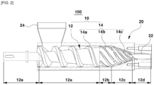
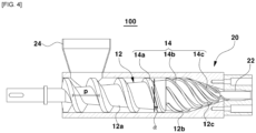
- FIGS. 2 through 4 are cross-sectional views illustrating embodiments of a high shear mixing unit 100 provided in the high shear mixing apparatus 500 of the present invention.
- the high shear mixing apparatus 500 of the present invention comprises: a high shear mixing unit 100 comprising a mixing screw 10 and a housing 20 receiving the mixing screw.
- the housing 20 comprises a nozzle 22 provided at a distal end thereof and a hopper 24 communicating therewith.
- the mixing screw 10 comprises a rotating shaft 12 and blades 14 provided on an outer surface of the rotating shaft.
- the rotating shaft 12 comprises, in this order, a first tapered portion 12a having a gradually increasing outer diameter in a direction toward the nozzle 22, a kneading portion 12b having a uniform outer diameter or a gradually increasing outer diameter in a direction toward the nozzle, and a second tapered portion 12c having a gradually decreasing outer diameter in a direction toward the nozzle.
- the blades 14 comprise first spiral blades 14a disposed on an outer surface of the first tapered portion 12a, second spiral blades 14b disposed on an outer surface of the kneading portion 12b, and third spiral blades 14c disposed on an outer surface of the second tapered portion 12c.
- the high shear mixing apparatus 500 of the present invention comprises a simple structure of a single-axis screw, such that it can be manufactured inexpensively and has the advantages of easy processing management and maintenance. In addition, it has the advantage of stable drive characteristics compared to a two-axis screw.
- the high shear mixing apparatus 500 of the present invention includes an improved mixing screw 10, which significantly improves compression and discharge forces for fibrillizable binder (e.g., PTFE) powders, and provides the advantage of easily controlling the degree of fibrillization and powder compaction ratio for fibrillizable binders.
- fibrillizable binder e.g., PTFE
- the length of the first tapered portion 12a, the length of the kneading portion 12b, and the length of the second tapered portion 12c on the rotating shaft 12 may be formed in a ratio of 1 : 0.1 to 0.3 : 0.2 to 0.45, preferably a ratio of 1 : 0.15 to 0.25 : 0.3 to 0.4.
- the length of the first tapered portion 12a may be 100 mm to 200 mm, preferably 120 mm to 160 mm.
- the length of the kneading portion 12b may be from 20 mm to 40 mm, preferably from 25 mm to 35 mm. If the length of the kneading portion is too short, the mixture object cannot be pushed to the top due to poor rotational motion, and if it is too long, the mixture object gets stuck and stagnation occurs.
- the length of the second tapered portion 12c may be from 30 mm to 70 mm, preferably from 40 mm to 60 mm, more preferably from 45 mm to 55 mm.
- the nozzle 22 may have a length of 40 mm to 80 mm, preferably 50 mm to 70 mm.
- the first tapered portion 12a may be tapered to form an angle of 3 to 6 degrees, preferably 4 to 5 degrees, with respect to the center axis of the rotating shaft 12. If the tapered angle is too large, the passage of the powder through the squeezing section is delayed by the phase change of the powder, so that the mixture object is stuck between the blades and stagnation occurs.
- the second tapered portion 12c may be tapered to form an angle of 15 to 22 degrees, preferably 16 to 20 degrees, with the respect to the center axis of the rotating shaft 12. If the angle that the second tapered portion 12c forms with respect to the center axis of the rotating shaft 12 is outside the above range, the mixture object (e.g., the electrode active material composition) is not ejected and it is difficult to fibrillize thereof properly.
- the mixture object e.g., the electrode active material composition
- the first spiral blades 14a and the second spiral blades 14b are formed independently, as shown in FIG. 3 .
- the pitch P of the first spiral blades 14a is larger than the pitch of the second spiral blades 14b, and the first spiral blades and the second spiral blades may be spirally wound in the same direction about the rotating shaft.
- the first spiral blades 14a function to perform mixing while conveying the mixture object (e.g., the electrode active material composition) being fed into the hopper 24 toward the nozzle. Furthermore, while mixing and conveying toward the nozzle, the mixture object passes over the wide blade surfaces of the inclined spirals, at which time the fibrillizing binder begins to be activated by the applied shearing force, and the initial fibrillizing stage (pre-fibrill) proceeds.
- the mixture object e.g., the electrode active material composition
- the pitch P between the first spiral blades 14a may be formed relatively large.
- it since kneading and high shear mixing are performed in the second spiral blades 14b, it may be effective to have a relatively small pitch P between the second spiral blades 14b.
- the pitch P of the first spiral blades 14a may be from 20 mm to 60 mm, and preferably from 35 mm to 50 mm.
- the pitch P of the first spiral blades 14a is less than the above-described range, the mixture object may get stuck in the space between the pitches and hinder the conveyance, which is undesirable because the mixture object may become difficult to pass over the first spiral blades and the initial fibrillation may not be efficient.
- the pitch P of the second spiral blades 14b may be from 8 mm to 25 mm, and preferably from 10 mm to 17 mm.
- pitch (P) of the second spiral blades 14b is less than the above-described range, it is undesirable because the device may be overloaded during high shear mixing, and if it exceeds the above-described range, it is undesirable because the disadvantage of insufficient kneading may occur.
- the maximum pitch (P) of the third spiral blades 14c may be 8 mm to 25 mm, preferably 10 mm to 17 mm, and the minimum pitch (P) may be 5 mm to 12 mm, preferably 6 mm to 10 mm.
- the third spiral blades 14c gradually decrease in pitch as they go toward the nozzle direction, i.e., at the starting point of the second tapered portion abutting the kneading portion, the third spiral blades 14c may be formed to have a maximum pitch, and the third spiral blades 14c may have a minimum pitch at the distal surface of the second tapered portion toward the nozzle.
- the pitch P of the third spiral blades 14c meets the above-described range, the free volume is gradually reduced as the pitch is gradually reduced, and further squeezing of the mixture object is achieved accordingly, and the effect of further increasing fibrillation as the mixture object passes over the third spiral blades may be obtained.
- the pitch P of the fourth spiral blades 14d provided on the outer surface of a front end shaft portion 12d may have a pitch of 30 mm to 50 mm, preferably 35 mm to 45 mm.
- the pitch of the fourth spiral blades meets the above-described range, a smooth discharge of the mixture object becomes possible, and further fibrillization can be achieved, which is desirable.
- the acute angle ( ⁇ in FIG. 3 ) of the second spiral blades 14b is larger than the acute angle of the first spiral blades 14a. This is because the first spiral blades 14a perform a function of mixing while conveying the mixture object (e.g., the electrode active material composition) fed into the hopper 24 toward the nozzle, so that the acute angle of the first spiral blades 14a may be formed relatively small.
- the mixture object e.g., the electrode active material composition
- the acute angle of the second spiral blades 14b should be relatively large so that a large pressure can be applied to the mixture object so as to accomplish effective kneading and mixing.
- the acute angle of the second spiral blades 14b may preferably be 1.5 times to 3 times, and more preferably 2 times to 2.5 times, larger than the acute angle of the first spiral blades 14a, as shown in FIG. 3 .
- the acute angle of the third spiral blades 14c may be larger than or equal to the acute angle of the second spiral blades 14b at a portion adjacent to the second spiral blades 14b, compared to the acute angle of the second spiral blades 14b. Further, the acute angle may be increasingly larger as it proceeds from the portion adjacent to the second spiral blades 14b to a portion adjacent to the distal surface of the second tapered portion.
- the acute angle is defined to mean the angle that a straight line connecting two center points of the outer surface of the spiral blades 14 makes with a cross-section perpendicular to the center axis of the rotating shaft 12, as shown in FIG. 3 .
- the acute angle of the first spiral blades 14a may be formed from 10 degrees to 40 degrees, preferably from 14 degrees to 20 degrees, and the acute angle of the second spiral blades 14b may be formed from 30 degrees to 55 degrees, preferably from 33 degrees to 41 degrees.
- the acute angle of the third spiral blades 14c may be formed at an acute angle of 30 degrees to 55 degrees, preferably 35 degrees to 45 degrees, at the portion adjacent to the second spiral blades 14b, with the acute angle increasingly larger as it proceeds from the portion adjacent to the second spiral blades 14b to the portion adjacent to the distal surface of the second tapered portion. Further, the acute angle may be formed finally at an acute angle of 40 degrees to 60 degrees, preferably 45 degrees to 55 degrees, at the portion adjacent to the distal surface of the second tapered portion.
- the acute angle of the spiral blades 14 is formed in a gradually increasing trend from the first spiral blades 14a toward the second spiral blades 14b and the third spiral blades 14c. If the acute angle is formed in the form of a gradually decreasing trend, a problem of clogging of the mixing unit may occur.
- the acute angle may be gradually increased as it proceeds toward the distal surface of the second tapered portion.
- an acute angle may be formed from 45 degrees to 55 degrees.
- nozzle clogging occurs, and if the acute angle is too small, nozzle clogging may occur, and if the acute angle is too large, clogging may occur due to decreased axial motion and increased rotational motion, and additional fibrillization is not expected.
- the perpendicular cross-section in the direction in which the first spiral blades 14a are wound about the rotating shaft 12 comprises two height-forming edges, as shown in FIG. 6 .
- one edge toward the nozzle 22 forms an acute angle ⁇ of 30 to 80 degrees, preferably 50 to 70 degrees, more preferably 55 to 65 degrees, with respect to the center axis of the rotating shaft in a direction opposite the nozzle 22 (see FIG. 3 ).
- Forming such an acute angle ( ⁇ ) is desirable because the mixture object (e.g., the electrode active material composition) is squeezed as it passes over the edge (leakage flow) having the acute angle ( ⁇ ) and is effectively fibrillized.
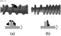
- the acute angle ( ⁇ ) is formed below the above-described range, leakage flow does not occur, so that a disadvantage occurs that sufficient preliminary fibrillation does not occur, and, if the acute angle ( ⁇ ) is formed above the above-described range, as shown in FIG. 11 , the mixture object does not pass over the edge and is simply conveyed and thus, not sufficiently squeezed, so that the fibrillation does not occur efficiently. In other words, in this case, only the outer surface is fibrillated, which is undesirable.
- one of the two height-forming edges opposite the nozzle 22 forms an angle of 60 to 90 degrees, preferably 80 to 90 degrees, with the center axis of the rotating shaft 12 in a direction toward the nozzle, as shown in FIG. 6 .
- Forming an angle as described above is preferred because preliminary fibrillation is maximized by circulation through the leakage flow without stagnation of the mixture object. If the angle exceeds 90 degrees, stagnation of the mixing material (e.g., electrode active material composition) may occur and circulation of the leakage flow is impeded, which is undesirable, and if the angle is less than 60 degrees, high shearing forces are not generated, which is undesirable.
- the mixing material e.g., electrode active material composition
- the perpendicular cross-section in the direction in which the first spiral blades 14a are wound about the rotating shaft 12 may further comprise, together with the two height-forming edges, one terminal edge in connection with the two height-forming edges, as shown in FIG. 6 .
- the terminal edge may be formed in a length of 4 mm to 10 mm, preferably in a length of 5 mm to 8 mm. If the terminal edges are formed below the above-described range, it is difficult to effectively squeeze the mixture object, and if they exceed the above-described range, it is undesirable because overloads are imposed on the device.
- the perpendicular cross-section in the direction in which the second spiral blades 14b are wound about the rotating shaft 12 comprises two height-forming edges, as shown in FIG. 6 .
- one edge toward the nozzle 22 forms an acute angle ⁇ of 40 to 80 degrees, preferably 50 to 70 degrees, more preferably 55 to 65 degrees, with respect to the center axis of the rotating shaft 12 in a direction opposite the nozzle.
- Forming such an acute angle ( ⁇ ) is desirable because the mixture object (e.g., the electrode-active material composition) is squeezed as it passes over the edge having the acute angle ( ⁇ ) and is effectively fibrillized.
- the acute angle ( ⁇ ) is formed below the above-described range, leakage flow does not occur and, accordingly, sufficient preliminary fibrillation does not occur, which is undesirable, and if the acute angle ( ⁇ ) is formed above the above-described range, the mixture object (e.g., the electrode active material composition) does not pass over the edge and is simply conveyed and is not sufficiently squeezed, so that fibrillation does not occur smoothly. In other words, in this case, only the outer surface is fibrillated, which is undesirable.
- the mixture object e.g., the electrode active material composition
- the one edge toward the nozzle 22 may be formed as a curve.
- the acute angle ⁇ is set relative to a tangent line passing through a midpoint of the length of the curve.
- the curve may have an R of 3 mm to 5 mm.
- the one edge toward the nozzle 22 may be formed with a lower portion formed by a straight line and an upper portion formed by a curve, as shown in FIG. 6 .
- the acute angle ⁇ is set based on an angle formed by the straight portion.
- the curved portion may have an R of 3 mm to 5 mm. When such a value of R is formed, it may be desirable because the mixture object smoothly passes over the blades.
- one of the two height-forming edges opposite the nozzle 22 forms an angle of 60 to 90 degrees, preferably 80 to 90 degrees, with respect to the center axis of the rotating shaft 12 in a direction toward the nozzle.
- the perpendicular cross-section in the direction wound about the rotating shaft 12 may further comprise, together with the two height-forming edges, one terminal edge connecting to the two height-forming edges.
- the terminal edge may be formed in a length of 0.3 mm to 0.8 mm, preferably in a length of 0.4 mm to 0.7 mm. If the terminal edges are formed below the above-described range, there will be insufficient generation of shearing force on the mixture object, and if they exceed the above-described range, the thickness of the second spiral blades 14b may become too thick and clogging may occur.
- the two edges of the height formation can be directly joined, without forming a terminal edge, as shown in FIG. 6 .
- the perpendicular cross-section of each of the third spiral blades 14c in the direction in which they are wound about the rotating shaft 12 includes two height-forming edges, as shown in FIG. 6 .
- the one edge toward the nozzle 22 forms an acute angle ⁇ of 40 to 70 degrees, preferably 55 to 65 degrees, with respect to the center axis of the rotating shaft 12 (see FIG. 3 ) in a direction opposite the nozzle.
- Forming such an acute angle ( ⁇ ) is desirable because the mixture object (e.g., the electrode-active material composition) is squeezed as it passes over the edge having the acute angle ( ⁇ ) and is effectively fibrillized.
- the acute angle ( ⁇ ) is formed below the above-described range, leakage flow does not occur and thus sufficient preliminary fibrillation is not achieved, and if the acute angle ( ⁇ ) is formed above the above-described range, the mixture object (e.g., the electrode active material composition) is simply conveyed without passing over the edge and is not sufficiently squeezed, and thus fibrillation is not efficiently achieved. In other words, in this case, only the outer surface is fibrillated, which is undesirable.
- the one edge toward the nozzle 22 may be formed as a curve.
- the acute angle ⁇ is set relative to a tangent line passing through a midpoint of the length of the curve.
- the curve may have an R of 3 mm to 5 mm. Forming a value of R thus described would be desirable because the mixture object passes smoothly over the blades.
- the one edge toward the nozzle 22 may be formed with a lower portion formed by a straight line and an upper portion formed by a curve, as shown in FIG. 6 .
- the acute angle ⁇ is set based on an angle formed by the straight portion.
- the curved portion may have an R of 3 mm to 5 mm.
- one of the two height-forming edges opposite the nozzle 22 forms an angle of 60 to 90 degrees, preferably 80 to 90 degrees, with respect to the center axis of the rotating shaft 12 in a direction toward the nozzle.
- the perpendicular cross-section in the direction wound about the rotating shaft 12 may further comprise, together with the two height-forming edges, one terminal edge connecting to the two height-forming edges.
- the terminal edge may be formed in a length of 0.3 mm to 0.8 mm, preferably in a length of 0.4 mm to 0.7 mm. If the terminal edges are formed below the above-described range, there will be an insufficient generation of shearing force on the mixture object, and if they exceed the above-described range, the thickness of the second spiral blades 14c may become too thick and clogging may occur.
- the one edge toward the nozzle 22 is formed as a curve or a combination of a curve and a straight line as described above, it may be in the form of a direct joining of the two edges of the height formation, without forming a terminal edge, as shown in FIG. 6 .
- the perpendicular cross-section in the direction in which the fourth spiral blades 14d are wound about the rotating shaft 12 includes two height-forming edges.
- one edge toward the nozzle 22 forms an acute angle ⁇ of 25 to 50 degrees, preferably 30 to 40 degrees, with respect to the center axis of the rotating shaft 12 in a direction opposite the nozzle.
- Forming such an acute angle ( ⁇ ) is desirable because the mixture object (e.g., the electrode-active material composition) is squeezed as it passes over the edge having the acute angle ( ⁇ ) and is effectively fibrillized.
- the acute angle ( ⁇ ) is formed below the above-described range, a disadvantage occurs that leakage flow does not occur and sufficient preliminary fibrillation does not occur, and if the acute angle ( ⁇ ) is formed above the above-described range, the mixture object (e.g., the electrode active material composition) is simply conveyed without passing over the edge and is not sufficiently squeezed, so that fibrillation does not occur efficiently. In other words, in this case, only the outer surface is fibrillated, which is undesirable.
- the mixture object e.g., the electrode active material composition
- the one edge toward the nozzle 22 may be formed by a lower part formed by a straight line and an upper part formed by a curved line, as shown in FIG. 6 .
- the acute angle ⁇ is set based on an angle formed by the straight portion.
- the curved portion may have an R of 0.4 mm to 0.6 mm.
- one of the two height-forming edges opposite the nozzle 22 forms an angle of 60 to 90 degrees, preferably 80 to 90 degrees, with respect to the center axis of the rotating shaft 12 in a direction toward the nozzle.
- the perpendicular cross-section in the direction of being wound about the rotating shaft 12 may be connected by a curve with the two height-forming variations R having a value of 0.4 mm to 0.6 mm.
- the first spiral blades 14a may be configured in a form in which a single spiral blade is continuously wound around the outer surface of the first tapered portion 12a.
- the one spiral blade may be formed in the form of 2 to 7 consecutive turns around the outer surface of the first tapered portion 12a, preferably 3 to 5 consecutive turns. If the first spiral blades are wound around the outer surface of the first tapered portion 12a beyond the above-described range, the initial fibrillation of the mixture object may not occur, and the pitch may be too tight, causing the mixture object to become stuck and not be conveyed.
- the second spiral blades 14b may comprise three or more independent blades superimposed on the outer surface of the kneading portion 12b.
- the number of the second spiral blades 14b may vary depending on the size of the high shear mixing apparatus, but generally may be from three to ten, preferably from four to eight, and even more preferably from four to six. Increasing the number of the blades can have the effect of increasing the fibrillization of the fibrillizable binder. However, an excessive number of blades is undesirable because it reduces the free volume generated by the blades and causes stagnation due to interference with the conveyance of the mixture object.
- each spiral blade may be formed with a length of 1/4 to 1 turn around the outer surface of the kneading portion 12b, preferably 1/4 to 1/2 turn, and more preferably 1/4 to 2/5 turn, as shown in FIG. 2 .
- the winding length may be influenced by the length of the kneading portion 12b and the acute angle of the blade.
- three or more independent blades are superimposed on the outer surface of the kneading portion 12b as described above, three or more spiral blades are spirally wound on the outer surface of the kneading portion 12b, as shown in FIG. 2 , from a starting point of the kneading portion 12b, extending to an end point of the kneading portion 12b.
- the second spiral blades 14b and the third spiral blades 14c may be spirally wound in the same direction about the rotating shaft 12.
- the third spiral blades 14c may comprise three or more independent blades superimposed on the outer surface of the second tapered portion 12c.
- the number of the third spiral blades 14c may vary depending on the size of the high shear mixing apparatus, but may typically be from three to ten, preferably from four to eight, and even more preferably from four to six. Increasing the number of the blades can have the effect of increasing the fibrillization of the fibrillizable binder. However, an excessive number of blades is undesirable because it reduces the free volume generated by the blades and causes stagnation due to interference with the conveyance of the mixture object.
- each spiral blade may be formed with a length of from 1/4 to 1 turn around the outer surface of the second tapered portion 12c, preferably from 2/5 to 3/5 turns.
- the winding length may be influenced by the length of the second tapered portion 12c and the acute angle of the blade.
- three or more spiral blades are spirally wound on the outer surface of the second tapered portion 12c from a starting point of the second tapered portion 12c, extending to an end point of the second tapered portion 12c, as shown in FIG. 2 .
- the end point of the second tapered portion 12c has a narrow cross-section as a tapered end
- the three or more spiral blades may be formed in a form that gradually narrows the spacing as they approach the end point. In this case, the pitch and free volume are reduced, and the effect is to increase fibrillation as the object to be further squeezed and mixed would escape the channel. In other words, high shear mixing can be achieved more effectively.
- the second spiral blades 14b and the third spiral blades 14c may be provided independently of each other, as shown in FIG. 2 .
- the second spiral blades 14b may extend to an outer surface of the second tapered portion 12c to form the third spiral blades 14c, as shown in FIG. 4 .
- a gap may be positioned between the second spiral blades 14b and the third spiral blades 14c, i.e., a gap is positioned between a terminal end of the kneading portion 12b of the rotating shaft 12 and a front end of the second tapered portion 12c, as shown in FIG. 2 .
- three or more independent blades provided on the second tapered portion 12c may be formed up to the outer periphery of the distal surface of the second tapered portion 12c toward the nozzle 22.
- the blades are formed up to the outer periphery of the distal surface of the second tapered portion 12c toward the nozzle 22, it is desirable because kneading and high shear mixing can be more effective, and the mixture object can be more easily delivered to the nozzle 22.
- the diameter of the distal surface of the second tapered portion 12c toward the nozzle 22 on the rotating shaft 12 may be from 0.5 to 1 times the inner diameter of the nozzle.
- the maximum diameter of the second tapered portion 12c may be from 2.1 times to 7.1 times the inner diameter of the nozzle, preferably from 3.1 times to 5.1 times.
- the maximum diameter of the first tapered portion 12a on the rotating shaft 12 may be from 2 to 7 times, preferably from 3 to 5 times, and the minimum diameter may be from 1 to 4 times, preferably from 1.5 to 2.5 times, the inner diameter of the nozzle.
- the maximum diameter of the kneading portion 12b at the rotating shaft 12 may be from 2.1 times to 7.1 times, preferably from 3.1 times to 5.1 times, the inner diameter of the nozzle, and the minimum diameter may be from 2 times to 7 times, preferably from 3 times to 5 times, the inner diameter of the nozzle.
- the outer diameter of the kneading portion 12b when it is uniformly formed, it may be formed in the range of the above minimum diameter.
- the height at which the first blades 14a protrude from the outer surface of the first tapered portion 12a may be from 10 mm to 20 mm, preferably from 13 mm to 18 mm.
- the outer periphery of the first blades 14a may have a separation distance from the inner surface of the housing of 0.2 mm to 3 mm, preferably 0.3 to 0.7 mm.
- the height of the second blades 14b protruding from the outer peripheral surface of the kneading portion 12b may be from 1 mm to 5 mm, preferably from 2 mm to 4 mm.
- the outer periphery of the second blades 14b may have a separation distance from the inner surface of the housing of 0.2 mm to 3 mm, preferably 0.3 to 0.7 mm.
- the height of the third blades 14c protruding from the outer peripheral surface of the second tapered portion 12c may be from 1 mm to 5 mm, preferably from 2 mm to 3.5 mm.
- the outer periphery of the third blades 14c may have a separation distance from the inner surface of the housing of 0.3 mm to 3 mm, preferably 0.5 to 1.1 mm.
- the height of the fourth blades 14d protruding from the outer peripheral surface of the front end shaft portion 12d may be from 0.5 mm to 3 mm, preferably from 0.7 mm to 1.3 mm.
- the outer periphery of the fourth blades 14d may have a separation distance from the inner surface of the housing of 0.8 mm to 3 mm, preferably 1 to 2 mm.
- the rotating shaft 12 may further comprise a front end shaft portion 12d extending into the nozzle from a distal end of the second tapered portion 12c toward the nozzle 22, as shown in FIG. 1 . It may further include a rear end shaft portion 12e extending from a distal end of the first tapered portion 12a opposite the nozzle 22.
- At least one of the front end shaft portion 12d and the rear end shaft portion 12e may be connected to the driving portion to perform a function of transmitting power to the mixing screw.
- the inner surface of the housing may have a roughness of 3 ⁇ m to 30 ⁇ m, preferably 5 ⁇ m to 15 ⁇ m. A roughness in the above-described range is preferred because it can improve the conveying efficiency and the fibrillization efficiency of the mixture object.
- the rotating shaft 12 comprises a first tapered portion 12a whose outer diameter gradually increases in a direction toward the nozzle, a kneading portion 12b having a uniform outer diameter or a gradually increasing outer diameter from a maximum outer diameter of the first tapered portion, and a second tapered portion 12c having a gradually decreasing outer diameter from an end of the kneading portion 12b continuously.
- the space between the first tapered portion 12a and the outer surface of the rotating shaft and the housing 20 is gradually reduced toward the nozzle 22
- the space between the outer surface of the kneading portion 12b and the housing 20 is gradually reduced or kept uniform as it goes toward the nozzle
- the space between the second tapered portion 12c and the housing 20 may be kept uniform or gradually reduced.
- the space between the outer surface of the kneading portion 12b and the housing 20 is maintained uniformly toward the nozzle. Furthermore, it may be further desirable that the space between the second tapered portion 12c and the housing 20 is maintained uniformly.
- the high shear mixing apparatus 500 effectively disperses the mixing material and effectively performs the fibrillization of the fibrillizable polymer, such as PTFE, contained in the mixing material. Furthermore, the fibrillization process of the fibrillizable polymer such as PTFE does not place a large load on the device. Therefore, the high shear mixing apparatus of the present invention having the above structure can be preferably used for high shear mixing for fabricating dry electrodes for secondary batteries, making it possible to build mass production equipment with a large capacity.
- the high shear mixing apparatus 500 may further comprise, in addition to the configurations described above, a driving portion 200 for powering the rotating shaft 12, as shown in FIG. 1 , and may further comprise, without limitation, configurations not mentioned above that are applicable to high shear mixing apparatuses of the art.
- the configurations of the present disclosure are self-explanatory to those of ordinary skill in the art, and therefore need not be described.
- the high shear mixing apparatus 500 of the present invention may further include a film forming apparatus 300 installed in association with the nozzle 22, as shown in FIG. 1 .
- the film forming apparatus 300 is not particularly limited and may be, for example, a device comprising a pair of pressing rollers.
- the primary mixture for the free-standing electrode was prepared by mixing 95.5 wt% or 97 wt% of NCM powder (trade name: GL80, LG Chem), anode active material particles with an average particle diameter of 10 ⁇ m, 1.5 wt% of Li250 (Denka) as a conductive material, and 1.5 wt% or 3 wt% of PTFE as a binder.
- the high shear mixing apparatus of the present invention (including the mixing screw of FIG. 5 ) and a conventional mixing apparatus were driven under conditions as shown in Table 1 to fabricate a secondary mixture in the form of a dough.
- the above dough-like secondary mixture was roll-pressed at 100°C using a two roll mill (MR-3, Inoue) to fabricate a 200 ⁇ m thick free-standing film.
- the thickness of the fabricated free-standing films in the embodiments and comparison examples was measured using an electrode thickness measurement device, Millimar (fabricated by Mahr), and the thickness was measured for a total of 25 points spaced at a distance of 1 cm from each other, with a size of 6 cm wide and 6 cm long relative to the MD direction of the fabricated free-standing films.
- Millimar fabricated by Mahr
- the above measurements were performed on four samples of free-standing film each, and the thickness variances were calculated for each sample and averaged to give the thickness variances shown in Table 1 below.
- the free-standing films fabricated in the embodiments and comparison examples were sampled by cutting them into 20 mm wide and 20 mm long pieces, and the tensile strength was measured at a speed of 50 mm/min by the 180 degree peel method using a LLOYD company UTM instrument.
- the maximum value of the force applied to the film during the above measurement up to the point where a fracture is about to occur is evaluated as the strength of the free-standing film, and the results of the above measurement are shown in Table 1 below.
- the anode was fabricated by placing the free-standing film fabricated in the embodiments and comparison examples on one edge of the collector of Primer Coated Aluminum Foil (fabricated by Dongwon Systems) with a thickness of 20 ⁇ m, and bonding it through a lamination roll maintained at 120°C.
- Primer Coated Aluminum Foil fabricated by Dongwon Systems
- lithium metal was used as the counter electrode, and an electrolyte containing 1 M of LiPF 6 in a solvent of EC : DMC : DEC (volume ratio of 1:2:1) was used to fabricate a coin-type half battery.
Landscapes
- Chemical & Material Sciences (AREA)
- Chemical Kinetics & Catalysis (AREA)
- Engineering & Computer Science (AREA)
- Mechanical Engineering (AREA)
- Processing And Handling Of Plastics And Other Materials For Molding In General (AREA)
- Mixers Of The Rotary Stirring Type (AREA)
- Battery Electrode And Active Subsutance (AREA)
Abstract
Description
- The present application claims the benefit and priority to
Korean Patent Application No. 10-2022-0121462, filed September 26, 2022 - The present invention relates to a high shear mixing apparatus, and more particularly to a high shear mixing apparatus used to fabricate dry electrodes for a secondary battery.
- Stirring devices are used in various paste manufacturing facilities and for fine mixing of chemical raw materials, such as inks, pigments, paints, cosmetics, pharmaceuticals and coatings, various coatings, abrasives, ceramic or metal powders, or various electronic materials (PZT, dielectric, MLCC, Ferrite, display materials). As a stirring device, a planetary mixer or twin screw extruder, which uses blades and rotors to stir high-viscosity materials in a container, is used, especially for stirring high-viscosity materials.
- On the other hand, with the expansion and development of secondary battery applications, improvements in low resistance, high capacity, mechanical properties, and productivity of electrodes are continuously required, and the need for high shear mixing of electrode fabrication mixtures is also increasing. Specifically, a technology for fabricating dry electrode films by mixing binders and conductive materials without liquid media such as solvents or dispersants, and then passing the powder mixture through a rolling roll is being actively developed, and high shear mixing is being applied to fabricate such electrodes.
- The high shear mixing methods described above use binders called "fibrillizable binders" or "fibril-forming binders," which, when subjected to high shear mixing in a mixture containing such binders, micro-fibrillate and bind the active and conductive materials.
- Conventional planetary mixers and twin screw extruders are used for the above high shear mixing method.
- However, during this high shear mixing process, the fibrillizable polymer becomes a chewing gum-like state, which puts a large load on the planetary mixer or twin screw extruder, and damage to the equipment often occurs. In order to prevent such equipment damage, a method of reducing the shearing force is considered, but in this case, the fibrillizable polymer is not well fibrillized. Therefore, it is very difficult to build a large-scale mass production system for fabricating dry electrodes for secondary batteries with conventional high shear mixing apparatus.
-
Korean Laid-open Publication No. 10-2011-0117902 - The present invention is designed to solve the above problems of the prior art, and aims to provide a high shear mixing apparatus that can efficiently mix materials without generating overload when mixing materials by high shearing force.
- In particular, it is an object to provide a high shear mixing apparatus capable of efficiently micro-fibrillating the polymer without generating an overload during high shear mixing of a mixture for fabricating a dry electrode comprising a fibrillizable polymer as a binder.
- In order to accomplish the above objectives, the present invention provides a high shear mixing apparatus, comprising: a mixing screw and a housing receiving the mixing screw; wherein the housing includes a nozzle provided at a distal end thereof and a hopper in communication therewith, wherein the mixing screw includes a rotating shaft and blades provided on an outer surface of the rotating shaft, wherein the rotating shaft has a first tapered portion having a gradually increasing outer diameter in a direction toward the nozzle, a kneading portion having a uniform outer diameter or a gradually increasing outer diameter in a direction toward the nozzle, and a second tapered portion having a gradually decreasing outer diameter in a direction toward the nozzle in this order, and wherein the blades comprise first spiral blades disposed on an outer surface of the first tapered portion, second spiral blades disposed on an outer surface of the kneading portion, and third spiral blades disposed on an outer surface of the second tapered portion.
- In an embodiment of the present invention, the first spiral blades and the second spiral blades may be independently formed, a pitch of the first spiral blades may be larger than a pitch of the second spiral blade, and the first spiral blades and the second spiral blades may be spirally wound in a same direction about the rotating shaft.
- In an embodiment of the present invention, an acute angle of the second spiral blades may be larger than an acute angle of the first spiral blades based on an acute angle formed by the spiral blades with respect to a cross-section perpendicular to a center axis of the rotating shaft.
- In an embodiment of the present invention, the second spiral blades may comprise three or more independent blades superimposed on an outer surface of the kneading portion.
- In an embodiment of the present invention, the second spiral blades and third spiral blades may be spirally wound in a same direction about the rotating shaft.
- In an embodiment of the present invention, the third spiral blades may comprise three or more independent blades superimposed on the outer surface of the second tapered portion.
- In an embodiment of the present invention, the second spiral blades and third spiral blades may be provided independently of each other.
- In an embodiment of the present invention, the second spiral blades may extend to the outer surface of the second tapered portion to form the third spiral blades.
- In an embodiment of the present invention, a gap may be positioned between the second spiral blades and the third spiral blades, and the gap may be positioned between a terminal end of the kneading portion and a front end of the second tapered portion of the rotating shaft.
- In an embodiment of the present invention, the three or more independent blades provided in the second tapered portion may be formed up to the distal surface of the second tapered portion toward the nozzle.
- In an embodiment of the present invention, a diameter of the distal surface of the second tapered portion in the rotating shaft toward the nozzle may be from 0.5 to 1 times, preferably 0.7 to 0.8 times, as large as an inner diameter of the nozzle.
- In an embodiment of the present invention, the rotating shaft may continuously comprise the first tapered portion having a gradually increasing outer diameter in a direction toward the nozzle, the kneading portion having a uniform outer diameter or a gradually increasing outer diameter from a maximum outer diameter of the first tapered portion, and the second tapered portion having a gradually decreasing outer diameter from an end of the kneading portion.
- In an embodiment of the present invention, a space between the outer surface of the first tapered portion of the rotating shaft and the housing may be gradually reduced toward the nozzle, a space between the outer surface of the kneading portion and the housing may be gradually reduced or kept uniform toward the nozzle, and a space between the second tapered portion and the housing may be kept uniform or gradually reduced.
- In an embodiment of the present invention, a length of the first tapered portion, a length of the kneading portion, and a length of the second tapered portion on the rotating shaft may be in a ratio of 1 : 0.1 to 0.3 : 0.2 to 0.45.
- In an embodiment of the present invention, an acute angle of the second spiral blades may be less than or equal to an acute angle of the third spiral blades based on an acute angle formed by the spiral blades with respect to a cross-section perpendicular to the center axis of the rotating shaft.
- In an embodiment of the present invention, the third spiral blades may have a maximum pitch at a starting point of the second tapered portion abutting the kneading portion, a minimum pitch at a distal surface of the second taper toward the nozzle, and the pitch may gradually decrease along the rotating shaft toward the nozzle.
- In an embodiment of the present invention, a perpendicular cross-section in a direction wound about the rotating shaft of the first spiral blades may include two height-forming edges, and one of the height-forming edges toward the nozzle may form an acute angle of 30 to 80 degrees, preferably 50 to 70 degrees, with respect to the center axis of the rotating shaft in a direction opposite the nozzle.
- In an embodiment of the present invention, a perpendicular cross-section in a direction wound about the rotating shaft of the second spiral blades may include two height-forming edges, and one of the height-forming edges toward the nozzle may form an acute angle of 40 to 80 degrees, preferably 50 to 70 degrees, with respect to the center axis of the rotating shaft in a direction opposite the nozzle.
- In an embodiment of the present invention, a perpendicular cross-section in a direction wound about the rotating shaft of the third spiral blades may include two height-forming edges, and one of the height-forming edges toward the nozzle may form an acute angle of 40 to 80 degrees, preferably 50 to 70 degrees, with respect to the center axis of the rotating shaft in a direction opposite the nozzle.
- In an embodiment of the present invention, the high shear mixing apparatus may be used for high shear mixing of a mixture for fabricating a dry electrode comprising a fibrillizable polymer as a binder so as to micro-fibrillate the fibrillizable polymer.
- The high shear mixing apparatus of the present invention provides an effect in which it is possible to mix materials efficiently without imposing overload when mixing materials by a high shearing force. Furthermore, since damage to the apparatus is minimized by this effect, the apparatus may be configured in a large capacity.
- In particular, the high shear mixing apparatus of the present invention provides the effect of efficiently micro-fibrillating the polymer without causing overloading during high shear mixing of a mixture for fabricating a dry electrode comprising a fibrillizable polymer as a binder.
-
-
FIG. 1 is a drawing schematically illustrating an embodiment of a high shear mixing apparatus of the present invention, -
FIGS. 2 through 4 are drawings illustrating an embodiment of a high shear mixing unit provided in a high shear mixing apparatus of the present invention, -
FIG. 5 is a drawing illustrating a specific resource of a high shear mixing unit provided in the high shear mixing apparatus of the present invention, -
FIG. 6 is a schematic illustration of a vertical cross-sectional view in the direction of winding about a rotating shaft of each of the blade portions provided in the high shear mixing apparatus of the present invention, -
FIG. 7 is a drawing illustrating the shape and material of each of the blade portions provided in the high shear mixing apparatus of the present invention, -
FIG. 8 is a photographic representation of the shape of a single-axis screw in a conventional mixing apparatus and the results of high shear mixing using it, -
FIG. 9 is a photographic representation of a conventional twin screw kneader, -
FIG. 10 is a photographic representation of a conventional single-axis screw used in polymer mixing applications and its state of use, -
FIG. 11 is a schematic illustration of a mixing mechanism in the form of first spiral blades provided in the present invention and in a conventional high shear mixing apparatus, and -
FIG. 12 is a drawing schematically illustrating the shape of third spiral blades provided in the high shear mixing apparatus of the present invention. - Hereinafter, embodiments of the present invention will be described in detail with reference to the accompanying drawings so that one having ordinary knowledge in the technical field to which the present invention belongs may readily practice the present invention. However, the present invention may be implemented in many different forms and is not limited to the embodiments described herein. Throughout the specification, like parts are designated by like drawing designations.
-
FIG. 1 is a perspective view illustrating an embodiment of a highshear mixing apparatus 500 of the present invention; andFIGS. 2 through 4 are cross-sectional views illustrating embodiments of a highshear mixing unit 100 provided in the highshear mixing apparatus 500 of the present invention. - The high
shear mixing apparatus 500 of the present invention, as shown inFIGS. 1 and2 , comprises: a highshear mixing unit 100 comprising amixing screw 10 and ahousing 20 receiving the mixing screw. - The
housing 20 comprises anozzle 22 provided at a distal end thereof and ahopper 24 communicating therewith. - The mixing
screw 10 comprises a rotatingshaft 12 andblades 14 provided on an outer surface of the rotating shaft. - The rotating
shaft 12 comprises, in this order, a firsttapered portion 12a having a gradually increasing outer diameter in a direction toward thenozzle 22, a kneadingportion 12b having a uniform outer diameter or a gradually increasing outer diameter in a direction toward the nozzle, and a second taperedportion 12c having a gradually decreasing outer diameter in a direction toward the nozzle. - The
blades 14 comprise firstspiral blades 14a disposed on an outer surface of the firsttapered portion 12a, secondspiral blades 14b disposed on an outer surface of thekneading portion 12b, and thirdspiral blades 14c disposed on an outer surface of the second taperedportion 12c. - The high
shear mixing apparatus 500 of the present invention comprises a simple structure of a single-axis screw, such that it can be manufactured inexpensively and has the advantages of easy processing management and maintenance. In addition, it has the advantage of stable drive characteristics compared to a two-axis screw. - In particular, the high
shear mixing apparatus 500 of the present invention includes animproved mixing screw 10, which significantly improves compression and discharge forces for fibrillizable binder (e.g., PTFE) powders, and provides the advantage of easily controlling the degree of fibrillization and powder compaction ratio for fibrillizable binders. - In an embodiment of the present invention, the length of the first
tapered portion 12a, the length of the kneadingportion 12b, and the length of the second taperedportion 12c on therotating shaft 12 may be formed in a ratio of 1 : 0.1 to 0.3 : 0.2 to 0.45, preferably a ratio of 1 : 0.15 to 0.25 : 0.3 to 0.4. - When the length ratio of the angular portions comprising the rotating
shaft 12 meets the above-described range, the dispersibility of the mixture object and the high shear mixing efficiency are increased, which is desirable. - In particular, if the length ratio of the kneading portion exceeds 0.3 in the above, it is undesirable because a problem of stagnation of the mixture object occurs.
- Specifically, for example, the length of the first
tapered portion 12a may be 100 mm to 200 mm, preferably 120 mm to 160 mm. The length of the kneadingportion 12b may be from 20 mm to 40 mm, preferably from 25 mm to 35 mm. If the length of the kneading portion is too short, the mixture object cannot be pushed to the top due to poor rotational motion, and if it is too long, the mixture object gets stuck and stagnation occurs. - The length of the second tapered
portion 12c may be from 30 mm to 70 mm, preferably from 40 mm to 60 mm, more preferably from 45 mm to 55 mm. Thenozzle 22 may have a length of 40 mm to 80 mm, preferably 50 mm to 70 mm. - In an embodiment of the present invention, as shown in
FIG. 5 , the firsttapered portion 12a may be tapered to form an angle of 3 to 6 degrees, preferably 4 to 5 degrees, with respect to the center axis of therotating shaft 12. If the tapered angle is too large, the passage of the powder through the squeezing section is delayed by the phase change of the powder, so that the mixture object is stuck between the blades and stagnation occurs. - Further, the second tapered
portion 12c may be tapered to form an angle of 15 to 22 degrees, preferably 16 to 20 degrees, with the respect to the center axis of therotating shaft 12. If the angle that the second taperedportion 12c forms with respect to the center axis of therotating shaft 12 is outside the above range, the mixture object (e.g., the electrode active material composition) is not ejected and it is difficult to fibrillize thereof properly. - In an embodiment of the present invention, the
first spiral blades 14a and thesecond spiral blades 14b are formed independently, as shown inFIG. 3 . Moreover, the pitch P of thefirst spiral blades 14a is larger than the pitch of thesecond spiral blades 14b, and the first spiral blades and the second spiral blades may be spirally wound in the same direction about the rotating shaft. - The
first spiral blades 14a function to perform mixing while conveying the mixture object (e.g., the electrode active material composition) being fed into thehopper 24 toward the nozzle. Furthermore, while mixing and conveying toward the nozzle, the mixture object passes over the wide blade surfaces of the inclined spirals, at which time the fibrillizing binder begins to be activated by the applied shearing force, and the initial fibrillizing stage (pre-fibrill) proceeds. - The pitch P between the
first spiral blades 14a may be formed relatively large. On the other hand, since kneading and high shear mixing are performed in thesecond spiral blades 14b, it may be effective to have a relatively small pitch P between thesecond spiral blades 14b. - In an embodiment of the present invention, the pitch P of the
first spiral blades 14a may be from 20 mm to 60 mm, and preferably from 35 mm to 50 mm. - If the pitch P of the
first spiral blades 14a is less than the above-described range, the mixture object may get stuck in the space between the pitches and hinder the conveyance, which is undesirable because the mixture object may become difficult to pass over the first spiral blades and the initial fibrillation may not be efficient. - The pitch P of the
second spiral blades 14b may be from 8 mm to 25 mm, and preferably from 10 mm to 17 mm. - If the pitch (P) of the
second spiral blades 14b is less than the above-described range, it is undesirable because the device may be overloaded during high shear mixing, and if it exceeds the above-described range, it is undesirable because the disadvantage of insufficient kneading may occur. - The maximum pitch (P) of the
third spiral blades 14c may be 8 mm to 25 mm, preferably 10 mm to 17 mm, and the minimum pitch (P) may be 5 mm to 12 mm, preferably 6 mm to 10 mm. - The
third spiral blades 14c gradually decrease in pitch as they go toward the nozzle direction, i.e., at the starting point of the second tapered portion abutting the kneading portion, thethird spiral blades 14c may be formed to have a maximum pitch, and thethird spiral blades 14c may have a minimum pitch at the distal surface of the second tapered portion toward the nozzle. - When the pitch P of the
third spiral blades 14c meets the above-described range, the free volume is gradually reduced as the pitch is gradually reduced, and further squeezing of the mixture object is achieved accordingly, and the effect of further increasing fibrillation as the mixture object passes over the third spiral blades may be obtained. - Meanwhile, the pitch P of the
fourth spiral blades 14d provided on the outer surface of a frontend shaft portion 12d may have a pitch of 30 mm to 50 mm, preferably 35 mm to 45 mm. When the pitch of the fourth spiral blades meets the above-described range, a smooth discharge of the mixture object becomes possible, and further fibrillization can be achieved, which is desirable. - In an embodiment of the present invention, considering an acute angle formed by the
spiral blades 14 with respect to a cross-section perpendicular to the center axis of therotating shaft 12, it may be desirable that the acute angle (α inFIG. 3 ) of thesecond spiral blades 14b is larger than the acute angle of thefirst spiral blades 14a. This is because thefirst spiral blades 14a perform a function of mixing while conveying the mixture object (e.g., the electrode active material composition) fed into thehopper 24 toward the nozzle, so that the acute angle of thefirst spiral blades 14a may be formed relatively small. On the other hand, since thesecond spiral blades 14b perform kneading and high shear mixing, the acute angle of thesecond spiral blades 14b should be relatively large so that a large pressure can be applied to the mixture object so as to accomplish effective kneading and mixing. - Specifically, the acute angle of the
second spiral blades 14b may preferably be 1.5 times to 3 times, and more preferably 2 times to 2.5 times, larger than the acute angle of thefirst spiral blades 14a, as shown inFIG. 3 . - Also, for the same reason, the acute angle of the
third spiral blades 14c may be larger than or equal to the acute angle of thesecond spiral blades 14b at a portion adjacent to thesecond spiral blades 14b, compared to the acute angle of thesecond spiral blades 14b. Further, the acute angle may be increasingly larger as it proceeds from the portion adjacent to thesecond spiral blades 14b to a portion adjacent to the distal surface of the second tapered portion. - In the present invention, the acute angle is defined to mean the angle that a straight line connecting two center points of the outer surface of the
spiral blades 14 makes with a cross-section perpendicular to the center axis of therotating shaft 12, as shown inFIG. 3 . - Specifically, in an embodiment of the present invention, the acute angle of the
first spiral blades 14a may be formed from 10 degrees to 40 degrees, preferably from 14 degrees to 20 degrees, and the acute angle of thesecond spiral blades 14b may be formed from 30 degrees to 55 degrees, preferably from 33 degrees to 41 degrees. - The acute angle of the
third spiral blades 14c may be formed at an acute angle of 30 degrees to 55 degrees, preferably 35 degrees to 45 degrees, at the portion adjacent to thesecond spiral blades 14b, with the acute angle increasingly larger as it proceeds from the portion adjacent to thesecond spiral blades 14b to the portion adjacent to the distal surface of the second tapered portion. Further, the acute angle may be formed finally at an acute angle of 40 degrees to 60 degrees, preferably 45 degrees to 55 degrees, at the portion adjacent to the distal surface of the second tapered portion. - In the present invention as a whole, the acute angle of the
spiral blades 14 is formed in a gradually increasing trend from thefirst spiral blades 14a toward thesecond spiral blades 14b and thethird spiral blades 14c. If the acute angle is formed in the form of a gradually decreasing trend, a problem of clogging of the mixing unit may occur. - In particular, within the
third spiral blades 14c, the acute angle may be gradually increased as it proceeds toward the distal surface of the second tapered portion. - If the acute angle of each of the
blades 14 does not meet the above-described range, it is undesirable because sufficient kneading and high shear mixing is not achieved. - Furthermore, in the case of the
fourth spiral blades 14d, an acute angle may be formed from 45 degrees to 55 degrees. In the absence of the fourth spiral blade, nozzle clogging occurs, and if the acute angle is too small, nozzle clogging may occur, and if the acute angle is too large, clogging may occur due to decreased axial motion and increased rotational motion, and additional fibrillization is not expected. - In an embodiment of the present invention, the perpendicular cross-section in the direction in which the
first spiral blades 14a are wound about the rotatingshaft 12 comprises two height-forming edges, as shown inFIG. 6 . In this case, one edge toward thenozzle 22 forms an acute angle β of 30 to 80 degrees, preferably 50 to 70 degrees, more preferably 55 to 65 degrees, with respect to the center axis of the rotating shaft in a direction opposite the nozzle 22 (seeFIG. 3 ). Forming such an acute angle (β) is desirable because the mixture object (e.g., the electrode active material composition) is squeezed as it passes over the edge (leakage flow) having the acute angle (β) and is effectively fibrillized. However, if the acute angle (β) is formed below the above-described range, leakage flow does not occur, so that a disadvantage occurs that sufficient preliminary fibrillation does not occur, and, if the acute angle (β) is formed above the above-described range, as shown inFIG. 11 , the mixture object does not pass over the edge and is simply conveyed and thus, not sufficiently squeezed, so that the fibrillation does not occur efficiently. In other words, in this case, only the outer surface is fibrillated, which is undesirable. - Furthermore, one of the two height-forming edges opposite the
nozzle 22 forms an angle of 60 to 90 degrees, preferably 80 to 90 degrees, with the center axis of therotating shaft 12 in a direction toward the nozzle, as shown inFIG. 6 . Forming an angle as described above is preferred because preliminary fibrillation is maximized by circulation through the leakage flow without stagnation of the mixture object. If the angle exceeds 90 degrees, stagnation of the mixing material (e.g., electrode active material composition) may occur and circulation of the leakage flow is impeded, which is undesirable, and if the angle is less than 60 degrees, high shearing forces are not generated, which is undesirable. - On the other hand, the perpendicular cross-section in the direction in which the
first spiral blades 14a are wound about the rotatingshaft 12 may further comprise, together with the two height-forming edges, one terminal edge in connection with the two height-forming edges, as shown inFIG. 6 . The terminal edge may be formed in a length of 4 mm to 10 mm, preferably in a length of 5 mm to 8 mm. If the terminal edges are formed below the above-described range, it is difficult to effectively squeeze the mixture object, and if they exceed the above-described range, it is undesirable because overloads are imposed on the device. - In an embodiment of the present invention, the perpendicular cross-section in the direction in which the
second spiral blades 14b are wound about the rotatingshaft 12 comprises two height-forming edges, as shown inFIG. 6 . In this case, one edge toward thenozzle 22 forms an acute angle β of 40 to 80 degrees, preferably 50 to 70 degrees, more preferably 55 to 65 degrees, with respect to the center axis of therotating shaft 12 in a direction opposite the nozzle. Forming such an acute angle (β) is desirable because the mixture object (e.g., the electrode-active material composition) is squeezed as it passes over the edge having the acute angle (β) and is effectively fibrillized. However, if the acute angle (β) is formed below the above-described range, leakage flow does not occur and, accordingly, sufficient preliminary fibrillation does not occur, which is undesirable, and if the acute angle (β) is formed above the above-described range, the mixture object (e.g., the electrode active material composition) does not pass over the edge and is simply conveyed and is not sufficiently squeezed, so that fibrillation does not occur smoothly. In other words, in this case, only the outer surface is fibrillated, which is undesirable. - The one edge toward the
nozzle 22 may be formed as a curve. In this case, the acute angle β is set relative to a tangent line passing through a midpoint of the length of the curve. In particular, the curve may have an R of 3 mm to 5 mm. - Further, the one edge toward the
nozzle 22 may be formed with a lower portion formed by a straight line and an upper portion formed by a curve, as shown inFIG. 6 . In this case, the acute angle β is set based on an angle formed by the straight portion. Specifically, the curved portion may have an R of 3 mm to 5 mm. When such a value of R is formed, it may be desirable because the mixture object smoothly passes over the blades. - Furthermore, one of the two height-forming edges opposite the
nozzle 22 forms an angle of 60 to 90 degrees, preferably 80 to 90 degrees, with respect to the center axis of therotating shaft 12 in a direction toward the nozzle. - In the
second spiral blades 14b, if the one edge toward thenozzle 22 is formed as a straight line, the perpendicular cross-section in the direction wound about the rotatingshaft 12 may further comprise, together with the two height-forming edges, one terminal edge connecting to the two height-forming edges. The terminal edge may be formed in a length of 0.3 mm to 0.8 mm, preferably in a length of 0.4 mm to 0.7 mm. If the terminal edges are formed below the above-described range, there will be insufficient generation of shearing force on the mixture object, and if they exceed the above-described range, the thickness of thesecond spiral blades 14b may become too thick and clogging may occur. - If the one edge toward the
nozzle 22 is formed as a curve, as described above, or a combination of a curve and a straight line, then the two edges of the height formation can be directly joined, without forming a terminal edge, as shown inFIG. 6 . - In an embodiment of the present invention, the perpendicular cross-section of each of the
third spiral blades 14c in the direction in which they are wound about the rotatingshaft 12 includes two height-forming edges, as shown inFIG. 6 . In this case, the one edge toward thenozzle 22 forms an acute angle β of 40 to 70 degrees, preferably 55 to 65 degrees, with respect to the center axis of the rotating shaft 12 (seeFIG. 3 ) in a direction opposite the nozzle. Forming such an acute angle (β) is desirable because the mixture object (e.g., the electrode-active material composition) is squeezed as it passes over the edge having the acute angle (β) and is effectively fibrillized. However, if the acute angle (β) is formed below the above-described range, leakage flow does not occur and thus sufficient preliminary fibrillation is not achieved, and if the acute angle (β) is formed above the above-described range, the mixture object (e.g., the electrode active material composition) is simply conveyed without passing over the edge and is not sufficiently squeezed, and thus fibrillation is not efficiently achieved. In other words, in this case, only the outer surface is fibrillated, which is undesirable. - Forming a R value thus described would be desirable because the mixing material passes smoothly over the blades.
- The one edge toward the
nozzle 22 may be formed as a curve. In this case, the acute angle β is set relative to a tangent line passing through a midpoint of the length of the curve. Specifically, the curve may have an R of 3 mm to 5 mm. Forming a value of R thus described would be desirable because the mixture object passes smoothly over the blades. - Further, the one edge toward the
nozzle 22 may be formed with a lower portion formed by a straight line and an upper portion formed by a curve, as shown inFIG. 6 . In this case, the acute angle β is set based on an angle formed by the straight portion. Specifically, the curved portion may have an R of 3 mm to 5 mm. - Furthermore, one of the two height-forming edges opposite the
nozzle 22 forms an angle of 60 to 90 degrees, preferably 80 to 90 degrees, with respect to the center axis of therotating shaft 12 in a direction toward the nozzle. - In the
third spiral blades 14c, if the one edge toward thenozzle 22 is formed as a straight line, the perpendicular cross-section in the direction wound about the rotatingshaft 12 may further comprise, together with the two height-forming edges, one terminal edge connecting to the two height-forming edges. The terminal edge may be formed in a length of 0.3 mm to 0.8 mm, preferably in a length of 0.4 mm to 0.7 mm. If the terminal edges are formed below the above-described range, there will be an insufficient generation of shearing force on the mixture object, and if they exceed the above-described range, the thickness of thesecond spiral blades 14c may become too thick and clogging may occur. - If the one edge toward the
nozzle 22 is formed as a curve or a combination of a curve and a straight line as described above, it may be in the form of a direct joining of the two edges of the height formation, without forming a terminal edge, as shown inFIG. 6 . - In an embodiment of the present invention, the perpendicular cross-section in the direction in which the
fourth spiral blades 14d are wound about the rotatingshaft 12 includes two height-forming edges. In this case, one edge toward thenozzle 22 forms an acute angle β of 25 to 50 degrees, preferably 30 to 40 degrees, with respect to the center axis of therotating shaft 12 in a direction opposite the nozzle. Forming such an acute angle (β) is desirable because the mixture object (e.g., the electrode-active material composition) is squeezed as it passes over the edge having the acute angle (β) and is effectively fibrillized. However, if the acute angle (β) is formed below the above-described range, a disadvantage occurs that leakage flow does not occur and sufficient preliminary fibrillation does not occur, and if the acute angle (β) is formed above the above-described range, the mixture object (e.g., the electrode active material composition) is simply conveyed without passing over the edge and is not sufficiently squeezed, so that fibrillation does not occur efficiently. In other words, in this case, only the outer surface is fibrillated, which is undesirable. - The one edge toward the
nozzle 22 may be formed by a lower part formed by a straight line and an upper part formed by a curved line, as shown inFIG. 6 . In this case, the acute angle β is set based on an angle formed by the straight portion. Specifically, the curved portion may have an R of 0.4 mm to 0.6 mm. - Furthermore, one of the two height-forming edges opposite the
nozzle 22 forms an angle of 60 to 90 degrees, preferably 80 to 90 degrees, with respect to the center axis of therotating shaft 12 in a direction toward the nozzle. - Meanwhile, in the
fourth spiral blades 14d, the perpendicular cross-section in the direction of being wound about the rotatingshaft 12 may be connected by a curve with the two height-forming variations R having a value of 0.4 mm to 0.6 mm. - In an embodiment of the present invention, the
first spiral blades 14a may be configured in a form in which a single spiral blade is continuously wound around the outer surface of the firsttapered portion 12a. In this case, the one spiral blade may be formed in the form of 2 to 7 consecutive turns around the outer surface of the firsttapered portion 12a, preferably 3 to 5 consecutive turns. If the first spiral blades are wound around the outer surface of the firsttapered portion 12a beyond the above-described range, the initial fibrillation of the mixture object may not occur, and the pitch may be too tight, causing the mixture object to become stuck and not be conveyed. - In an embodiment of the present invention, the
second spiral blades 14b may comprise three or more independent blades superimposed on the outer surface of the kneadingportion 12b. The number of thesecond spiral blades 14b may vary depending on the size of the high shear mixing apparatus, but generally may be from three to ten, preferably from four to eight, and even more preferably from four to six. Increasing the number of the blades can have the effect of increasing the fibrillization of the fibrillizable binder. However, an excessive number of blades is undesirable because it reduces the free volume generated by the blades and causes stagnation due to interference with the conveyance of the mixture object. - When three or more independent blades are superimposed on the outer surface of the kneading
portion 12b as described above, each spiral blade may be formed with a length of 1/4 to 1 turn around the outer surface of the kneadingportion 12b, preferably 1/4 to 1/2 turn, and more preferably 1/4 to 2/5 turn, as shown inFIG. 2 . The winding length may be influenced by the length of the kneadingportion 12b and the acute angle of the blade. - When three or more independent blades are superimposed on the outer surface of the kneading
portion 12b as described above, three or more spiral blades are spirally wound on the outer surface of the kneadingportion 12b, as shown inFIG. 2 , from a starting point of the kneadingportion 12b, extending to an end point of the kneadingportion 12b. In this case, it may be desirable for the blades to form a regular spacing. - In an embodiment of the present invention, the
second spiral blades 14b and thethird spiral blades 14c may be spirally wound in the same direction about the rotatingshaft 12. - In an embodiment of the present invention, the
third spiral blades 14c may comprise three or more independent blades superimposed on the outer surface of the second taperedportion 12c. The number of thethird spiral blades 14c may vary depending on the size of the high shear mixing apparatus, but may typically be from three to ten, preferably from four to eight, and even more preferably from four to six. Increasing the number of the blades can have the effect of increasing the fibrillization of the fibrillizable binder. However, an excessive number of blades is undesirable because it reduces the free volume generated by the blades and causes stagnation due to interference with the conveyance of the mixture object. - When three or more independent blades are superimposed on the outer surface of the second tapered
portion 12c, as shown inFIG. 2 , each spiral blade may be formed with a length of from 1/4 to 1 turn around the outer surface of the second taperedportion 12c, preferably from 2/5 to 3/5 turns. The winding length may be influenced by the length of the second taperedportion 12c and the acute angle of the blade. - When three or more independent blades are superimposed on the outer surface of the second tapered
portion 12c as described above, three or more spiral blades are spirally wound on the outer surface of the second taperedportion 12c from a starting point of the second taperedportion 12c, extending to an end point of the second taperedportion 12c, as shown inFIG. 2 . In this case, it may be desirable for the blades to form a regular spacing. However, since the end point of the second taperedportion 12c has a narrow cross-section as a tapered end, the three or more spiral blades may be formed in a form that gradually narrows the spacing as they approach the end point. In this case, the pitch and free volume are reduced, and the effect is to increase fibrillation as the object to be further squeezed and mixed would escape the channel. In other words, high shear mixing can be achieved more effectively. - In an embodiment of the present invention, the
second spiral blades 14b and thethird spiral blades 14c may be provided independently of each other, as shown inFIG. 2 . - In an embodiment of the present invention, the
second spiral blades 14b may extend to an outer surface of the second taperedportion 12c to form thethird spiral blades 14c, as shown inFIG. 4 . - In an embodiment of the present invention, a gap may be positioned between the
second spiral blades 14b and thethird spiral blades 14c, i.e., a gap is positioned between a terminal end of the kneadingportion 12b of therotating shaft 12 and a front end of the second taperedportion 12c, as shown inFIG. 2 . When the gap is formed in this manner, movement of the mixture object is possible through the gap, so that the effect of mitigating the torque on the second tapered portion can be achieved. - In an embodiment of the present invention, three or more independent blades provided on the second tapered
portion 12c may be formed up to the outer periphery of the distal surface of the second taperedportion 12c toward thenozzle 22. When the blades are formed up to the outer periphery of the distal surface of the second taperedportion 12c toward thenozzle 22, it is desirable because kneading and high shear mixing can be more effective, and the mixture object can be more easily delivered to thenozzle 22. - In an embodiment of the present invention, the diameter of the distal surface of the second tapered
portion 12c toward thenozzle 22 on therotating shaft 12 may be from 0.5 to 1 times the inner diameter of the nozzle. Further, the maximum diameter of the second taperedportion 12c may be from 2.1 times to 7.1 times the inner diameter of the nozzle, preferably from 3.1 times to 5.1 times. - In an embodiment of the present invention, the maximum diameter of the first
tapered portion 12a on therotating shaft 12 may be from 2 to 7 times, preferably from 3 to 5 times, and the minimum diameter may be from 1 to 4 times, preferably from 1.5 to 2.5 times, the inner diameter of the nozzle. - In an embodiment of the present invention, the maximum diameter of the kneading
portion 12b at therotating shaft 12 may be from 2.1 times to 7.1 times, preferably from 3.1 times to 5.1 times, the inner diameter of the nozzle, and the minimum diameter may be from 2 times to 7 times, preferably from 3 times to 5 times, the inner diameter of the nozzle. In this case, when the outer diameter of the kneadingportion 12b is uniformly formed, it may be formed in the range of the above minimum diameter. - In an embodiment of the present invention, the height at which the
first blades 14a protrude from the outer surface of the firsttapered portion 12a may be from 10 mm to 20 mm, preferably from 13 mm to 18 mm. The outer periphery of thefirst blades 14a may have a separation distance from the inner surface of the housing of 0.2 mm to 3 mm, preferably 0.3 to 0.7 mm. - In an embodiment of the present invention, the height of the
second blades 14b protruding from the outer peripheral surface of the kneadingportion 12b may be from 1 mm to 5 mm, preferably from 2 mm to 4 mm. The outer periphery of thesecond blades 14b may have a separation distance from the inner surface of the housing of 0.2 mm to 3 mm, preferably 0.3 to 0.7 mm. - In an embodiment of the present invention, the height of the
third blades 14c protruding from the outer peripheral surface of the second taperedportion 12c may be from 1 mm to 5 mm, preferably from 2 mm to 3.5 mm. The outer periphery of thethird blades 14c may have a separation distance from the inner surface of the housing of 0.3 mm to 3 mm, preferably 0.5 to 1.1 mm. - In an embodiment of the present invention, the height of the
fourth blades 14d protruding from the outer peripheral surface of the frontend shaft portion 12d may be from 0.5 mm to 3 mm, preferably from 0.7 mm to 1.3 mm. The outer periphery of thefourth blades 14d may have a separation distance from the inner surface of the housing of 0.8 mm to 3 mm, preferably 1 to 2 mm. - In the above, if the separation distance between each blade and the inner surface of the housing is too small, the mixing material cannot be squeezed as it escapes, making it difficult to fibrillize effectively, i.e., only the outer surface may be fibrillized. On the other hand, a separation distance that is too large is undesirable because it reduces the compaction efficiency.
- In an embodiment of the present invention, the rotating
shaft 12 may further comprise a frontend shaft portion 12d extending into the nozzle from a distal end of the second taperedportion 12c toward thenozzle 22, as shown inFIG. 1 . It may further include a rearend shaft portion 12e extending from a distal end of the firsttapered portion 12a opposite thenozzle 22. - At least one of the front
end shaft portion 12d and the rearend shaft portion 12e may be connected to the driving portion to perform a function of transmitting power to the mixing screw. - In an embodiment of the present invention, the inner surface of the housing may have a roughness of 3 µm to 30 µm, preferably 5 µm to 15 µm. A roughness in the above-described range is preferred because it can improve the conveying efficiency and the fibrillization efficiency of the mixture object.
- In an embodiment of the present invention, the rotating
shaft 12 comprises a firsttapered portion 12a whose outer diameter gradually increases in a direction toward the nozzle, a kneadingportion 12b having a uniform outer diameter or a gradually increasing outer diameter from a maximum outer diameter of the first tapered portion, and a second taperedportion 12c having a gradually decreasing outer diameter from an end of the kneadingportion 12b continuously. - In an embodiment of the present invention, the space between the first
tapered portion 12a and the outer surface of the rotating shaft and thehousing 20 is gradually reduced toward thenozzle 22, the space between the outer surface of the kneadingportion 12b and thehousing 20 is gradually reduced or kept uniform as it goes toward the nozzle, and the space between the second taperedportion 12c and thehousing 20 may be kept uniform or gradually reduced. - In the above, it may be more desirable that the space between the outer surface of the kneading
portion 12b and thehousing 20 is maintained uniformly toward the nozzle. Furthermore, it may be further desirable that the space between the second taperedportion 12c and thehousing 20 is maintained uniformly. - In an embodiment of the present invention, the high
shear mixing apparatus 500 effectively disperses the mixing material and effectively performs the fibrillization of the fibrillizable polymer, such as PTFE, contained in the mixing material. Furthermore, the fibrillization process of the fibrillizable polymer such as PTFE does not place a large load on the device. Therefore, the high shear mixing apparatus of the present invention having the above structure can be preferably used for high shear mixing for fabricating dry electrodes for secondary batteries, making it possible to build mass production equipment with a large capacity. - In particular, when a mixture comprising an active material, a conductive material, and a fibrillizable binder such as PTFE as a binder is subjected to high shear mixing, and a dry free-standing electrode is fabricated by rolling the mixed mixture, the tensile strength of the free-standing electrode is greatly improved, and such a dry free-standing electrode provides an effect of greatly improving the life of the secondary battery.
- In an embodiment of the present invention, the high
shear mixing apparatus 500 may further comprise, in addition to the configurations described above, a drivingportion 200 for powering the rotatingshaft 12, as shown inFIG. 1 , and may further comprise, without limitation, configurations not mentioned above that are applicable to high shear mixing apparatuses of the art. The configurations of the present disclosure are self-explanatory to those of ordinary skill in the art, and therefore need not be described. - In addition, the high
shear mixing apparatus 500 of the present invention may further include afilm forming apparatus 300 installed in association with thenozzle 22, as shown inFIG. 1 . Thefilm forming apparatus 300 is not particularly limited and may be, for example, a device comprising a pair of pressing rollers. - Hereinafter, the present invention will be described in detail with reference to embodiments. However, the embodiments according to the present invention may be modified in various other forms, and the scope of the present invention should not be construed as being limited to the embodiments described below. The embodiments of the present invention are provided to more fully illustrate the present invention to one of ordinary skill in the art.
- The primary mixture for the free-standing electrode was prepared by mixing 95.5 wt% or 97 wt% of NCM powder (trade name: GL80, LG Chem), anode active material particles with an average particle diameter of 10 µm, 1.5 wt% of Li250 (Denka) as a conductive material, and 1.5 wt% or 3 wt% of PTFE as a binder.
- The high shear mixing apparatus of the present invention (including the mixing screw of
FIG. 5 ) and a conventional mixing apparatus were driven under conditions as shown in Table 1 to fabricate a secondary mixture in the form of a dough. - The above dough-like secondary mixture was roll-pressed at 100°C using a two roll mill (MR-3, Inoue) to fabricate a 200 µm thick free-standing film.
- The thickness of the fabricated free-standing films in the embodiments and comparison examples was measured using an electrode thickness measurement device, Millimar (fabricated by Mahr), and the thickness was measured for a total of 25 points spaced at a distance of 1 cm from each other, with a size of 6 cm wide and 6 cm long relative to the MD direction of the fabricated free-standing films. The above measurements were performed on four samples of free-standing film each, and the thickness variances were calculated for each sample and averaged to give the thickness variances shown in Table 1 below.
- The free-standing films fabricated in the embodiments and comparison examples were sampled by cutting them into 20 mm wide and 20 mm long pieces, and the tensile strength was measured at a speed of 50 mm/min by the 180 degree peel method using a LLOYD company UTM instrument. The maximum value of the force applied to the film during the above measurement up to the point where a fracture is about to occur is evaluated as the strength of the free-standing film, and the results of the above measurement are shown in Table 1 below.
- The anode was fabricated by placing the free-standing film fabricated in the embodiments and comparison examples on one edge of the collector of Primer Coated Aluminum Foil (fabricated by Dongwon Systems) with a thickness of 20 µm, and bonding it through a lamination roll maintained at 120°C.
- Using the anode fabricated above, lithium metal was used as the counter electrode, and an electrolyte containing 1 M of LiPF6 in a solvent of EC : DMC : DEC (volume ratio of 1:2:1) was used to fabricate a coin-type half battery.
- After charging and discharging the coin-type half battery fabricated above 100 times at 25°C, under the conditions of a voltage range of 3 to 4.3V and current of 0.33 C-rate, the retention rate of 100 times discharge capacity compared to the capacity of one time discharge was calculated, and the results are shown in Table 1 below.
[Table 1] Mixing Apparatus MixingRPM /Temperatu re Conduct ive material content (wt%) Binder Content (wt%) Thickness variances based on 200 µm of free-standing film (%) Based on 200µm free-standing film Tensile Strength (gf/cm2) 0.33C/0.33C Room Temperature Lifetime (Capa Efficiency, % @100 cycle Embodi ment 1 High shear mixing apparatus of the present invention 100 RPM/90 1.5 1.5 ± 0.3 2,476 96.3 Embodi ment 2High shear mixing apparatus of the present invention 100 RPM/90 1.5 3.0 ± 0.4 2,831 97.1 Compar ison Exampl e 1Conventional Single Screw Extruder (with mixing screw in FIG. 8 )100 RPM/90 1.5 3.0 ± 1.8 1,824 95.4 Compar ison Exampl e 2Conventional Twin Screw Extruder 100 RPM/90 1.5 3.0 Unable to extrude (machine stopped) -. -. Compar ison Exampl e 3Conventional Twin Screw Kneader ( FIG. 9 ) +Roll Press 100 RPM/90 1.5 3.0 ±8.3 1983 94.7 Compar ison Exampl e 4Conventional Twin Screw Kneader ( FIG. 9 ) +Roll Press 100 RPM/room temperatur e 1.5 3.0 ± 10.9 1716 93.2 Compar ison Exampl e 5 Conventional Paste Mixer + Roll Press 1,000 RPM/room temperatur e 1.5 3.0 ± 6.4 1652 91.9 Compar ison Exampl e 6 Conventional Lab Blender + Roll Press 10,000 -RPM/room temperatur e 1.5 3.0 ± 4.7 1597 88.5 - Although the present invention has been described with reference to the above-mentioned preferred embodiments,
- It is possible to make various modifications and variations without departing from the spirit and scope of the invention. Accordingly, the appended claims of the patent are intended to cover such modifications or variations as long as they fall within the spirit of the present invention.
-
10: Mixing screw 12: Rotating shaft 12a: First tapered portion 12b: Kneading portion 12c: Second tapered portion 12d: Front end of shaft portion 12e: Rear end of shaft portion 14: Blades 14a: First spiral blades 14b: Second spiral blades 14c: Third spiral blades 14d: Fourth spiral blades 20: Housing 22: Nozzle 24: Hopper 100: High shear mixing unit 200: Driving portion 300: Film forming apparatus
Claims (20)
- A high shear mixing apparatus, comprising:a mixing screw and a housing receiving the mixing screw;wherein the housing includes a nozzle provided at a distal end thereof and a hopper in communication therewith,wherein the mixing screw includes a rotating shaft and blades provided on an outer surface of the rotating shaft,wherein the rotating shaft has a first tapered portion having a gradually increasing outer diameter in a direction toward the nozzle, a kneading portion having a uniform outer diameter or a gradually increasing outer diameter in the direction toward the nozzle, and a second tapered portion having a gradually decreasing outer diameter in the direction toward the nozzle in this order, andwherein the blades comprise first spiral blades disposed on an outer surface of the first tapered portion, second spiral blades disposed on an outer surface of the kneading portion, and third spiral blades disposed on an outer surface of the second tapered portion.
- The high shear mixing apparatus of claim 1,
wherein the first spiral blades and the second spiral blades are independently formed, a pitch of the first spiral blades is larger than a pitch of the second spiral blade, and the first spiral blades and the second spiral blades are spirally wound in a same direction about the rotating shaft. - The high shear mixing apparatus of claim 2,
wherein an acute angle of the second spiral blades is larger than an acute angle of the first spiral blades based on an acute angle formed by the spiral blades with respect to a cross-section perpendicular to a center axis of the rotating shaft. - The high shear mixing apparatus of claim 3,
wherein the second spiral blades comprise three or more independent blades superimposed on the outer surface of the kneading portion. - The high shear mixing apparatus of claim 4,
wherein the second spiral blades and third spiral blades are spirally wound in a same direction about the rotating shaft. - The high shear mixing apparatus of claim 5,
wherein the third spiral blades comprise three or more independent blades superimposed on the outer surface of the second tapered portion. - The high shear mixing apparatus of claim 6,
wherein the second spiral blades and third spiral blades are provided independently of each other. - The high shear mixing apparatus of claim 6,
wherein the second spiral blades extend to the outer surface of the second tapered portion to form the third spiral blades. - The high shear mixing apparatus of claim 8,
wherein a gap is positioned between the second spiral blades and the third spiral blades, wherein the gap is positioned between a terminal end of the kneading portion and a front end of the second tapered portion of the rotating shaft. - The high shear mixing apparatus of claim 6,
wherein the three or more independent blades provided in the second tapered portion are formed up to a periphery of a distal surface of the second tapered portion toward the nozzle. - The high shear mixing apparatus of claim 10,
wherein a diameter of the distal surface of the second tapered portion in the rotating shaft toward the nozzle is from 0.5 to 2.0 times as large as an inner diameter of the nozzle. - The high shear mixing apparatus of claim 1,
wherein the rotating shaft continuously comprises the first tapered portion having a gradually increasing outer diameter in a direction toward the nozzle, the kneading portion having the uniform outer diameter or the gradually increasing outer diameter from a maximum outer diameter of the first tapered portion, and the second tapered portion having a gradually decreasing outer diameter from an end of the kneading portion. - The high shear mixing apparatus of claim 1,
wherein a space between the outer surface of the first tapered portion of the rotating shaft and the housing is gradually reduced toward the nozzle, a space between the outer surface of the kneading portion and the housing is gradually reduced or kept uniform toward the nozzle, and a space between the second tapered portion and the housing is kept uniform or gradually reduced. - The high shear mixing apparatus of claim 1,
wherein a length of the first tapered portion, a length of the kneading portion, and a length of the second tapered portion on the rotating shaft are in a ratio of 1 : 0.1 to 0.4 : 0.2 to 0.5. - The high shear mixing apparatus of claim 6,
wherein an acute angle of the second spiral blades is less than or equal to an acute angle of the third spiral blades based on an acute angle formed by the spiral blades with respect to a cross-section perpendicular to the center axis of the rotating shaft. - The high shear mixing apparatus of claim 6,
wherein the third spiral blades have a maximum pitch at a starting point of the second tapered portion abutting the kneading portion, a minimum pitch at a distal surface of the second taper toward the nozzle, and the pitch gradually decreases along the rotating shaft toward the nozzle. - The high shear mixing apparatus of claim 6,
wherein a perpendicular cross-section in a direction wound about the rotating shaft of the first spiral blades includes two height-forming edges, wherein one of the height-forming edges toward the nozzle forms an acute angle of 30 to 80 degrees with respect to the center axis of the rotating shaft in a direction opposite the nozzle. - The high shear mixing apparatus of claim 17,
wherein a perpendicular cross-section in a direction wound about the rotating shaft of the second spiral blades includes two height-forming edges, wherein one of the height-forming edges toward the nozzle forms an acute angle of 40 to 80 degrees with respect to the center axis of the rotating shaft in a direction opposite the nozzle. - The high shear mixing apparatus of claim 18,
wherein a perpendicular cross-section in a direction wound about the rotating shaft of the third spiral blades includes two height-forming edges, wherein one of the height-forming edges toward the nozzle forms an acute angle of 40 to 80 degrees with respect to the center axis of the rotating shaft in the direction opposite the nozzle. - The high shear mixing apparatus of claim 1,
wherein the high shear mixing apparatus is used for high shear mixing of a mixture for fabricating a dry electrode comprising a fibrillizable polymer as a binder so as to micro-fibrillate the fibrillizable polymer.
Applications Claiming Priority (2)
| Application Number | Priority Date | Filing Date | Title |
|---|---|---|---|
| KR1020220121462A KR102893458B1 (en) | 2022-09-26 | 2022-09-26 | High shear mixing device |
| PCT/KR2023/014688 WO2024071917A1 (en) | 2022-09-26 | 2023-09-25 | High-shear mixing apparatus |
Publications (3)
| Publication Number | Publication Date |
|---|---|
| EP4450151A1 true EP4450151A1 (en) | 2024-10-23 |
| EP4450151A4 EP4450151A4 (en) | 2025-07-23 |
| EP4450151B1 EP4450151B1 (en) | 2026-05-13 |
Family
ID=90478669
Family Applications (1)
| Application Number | Title | Priority Date | Filing Date |
|---|---|---|---|
| EP23873033.7A Active EP4450151B1 (en) | 2022-09-26 | 2023-09-25 | High-shear mixing apparatus |
Country Status (6)
| Country | Link |
|---|---|
| US (1) | US20250269338A1 (en) |
| EP (1) | EP4450151B1 (en) |
| JP (1) | JP7785972B2 (en) |
| KR (1) | KR102893458B1 (en) |
| CN (1) | CN118541209A (en) |
| WO (1) | WO2024071917A1 (en) |
Family Cites Families (15)
| Publication number | Priority date | Publication date | Assignee | Title |
|---|---|---|---|---|
| FR2446706A1 (en) * | 1979-01-18 | 1980-08-14 | Ems Ind | CONTINUOUS MIXER FOR POLYMERS |
| DE69314802T2 (en) * | 1992-09-26 | 1998-05-14 | Robin Hamilton | METHOD AND DEVICE FOR COMPRESSING |
| JP2857574B2 (en) * | 1993-11-10 | 1999-02-17 | 富士車輌株式会社 | Extrusion molding machine |
| JP3013226B2 (en) * | 1994-04-28 | 2000-02-28 | 株式会社日本製鋼所 | Manufacturing method of metal molded products |
| JP2002224891A (en) | 2001-02-01 | 2002-08-13 | Hitachi Zosen Corp | Waste dewatering apparatus and operating method thereof |
| JP2002239360A (en) * | 2001-02-21 | 2002-08-27 | Fuji Carbon Kk | Apparatus for agitating treatment material |
| CN101184560B (en) * | 2005-05-27 | 2010-05-12 | 宫代知直 | Apparatus for treatment of organic waste material and method for separating and recovering liquid material |
| JP2007061882A (en) * | 2005-09-01 | 2007-03-15 | Kobe Steel Ltd | Injection molding machine, and screw for injection molding machine |
| JP4951558B2 (en) * | 2008-03-19 | 2012-06-13 | 日本碍子株式会社 | Clay mill |
| KR101178017B1 (en) | 2010-04-22 | 2012-08-29 | 김경호 | Pressurization type kneader |
| JP6085398B2 (en) * | 2012-08-03 | 2017-02-22 | 有限会社石塚機械設計事務所 | mixer |
| CN108698001B (en) * | 2016-03-01 | 2022-08-02 | Sika技术股份公司 | Mixer, system for applying construction material and method for manufacturing a structure from construction material |
| US10434483B2 (en) * | 2017-02-15 | 2019-10-08 | Wenger Manufacturing Inc. | High thermal transfer hollow core extrusion screw assembly |
| KR102466129B1 (en) | 2021-02-25 | 2022-11-14 | 한국생산기술연구원 | Methods and systems for production of synthetic gas |
| CN215877045U (en) * | 2021-04-06 | 2022-02-22 | 无锡灵鸽机械科技股份有限公司 | Reciprocating type single-screw continuous stirring and dispersing device for preparing lithium battery slurry |
-
2022
- 2022-09-26 KR KR1020220121462A patent/KR102893458B1/en active Active
-
2023
- 2023-09-25 EP EP23873033.7A patent/EP4450151B1/en active Active
- 2023-09-25 CN CN202380016923.3A patent/CN118541209A/en active Pending
- 2023-09-25 WO PCT/KR2023/014688 patent/WO2024071917A1/en not_active Ceased
- 2023-09-25 US US18/857,150 patent/US20250269338A1/en active Pending
- 2023-09-25 JP JP2024557181A patent/JP7785972B2/en active Active
Also Published As
| Publication number | Publication date |
|---|---|
| EP4450151A4 (en) | 2025-07-23 |
| JP2025512830A (en) | 2025-04-22 |
| KR20240042772A (en) | 2024-04-02 |
| KR102893458B1 (en) | 2025-12-03 |
| US20250269338A1 (en) | 2025-08-28 |
| EP4450151B1 (en) | 2026-05-13 |
| JP7785972B2 (en) | 2025-12-15 |
| CN118541209A (en) | 2024-08-23 |
| WO2024071917A1 (en) | 2024-04-04 |
Similar Documents
| Publication | Publication Date | Title |
|---|---|---|
| CN217042141U (en) | Cylinder dispersing device | |
| CN103682252B (en) | Electrode paste production device and electrode slurry manufacture method | |
| EP1360732B1 (en) | Method for making electrode | |
| CN217042144U (en) | Go up feeding powder liquid mixing arrangement | |
| CN112871051B (en) | Double-screw extruder and mixing method thereof | |
| EP4224550A1 (en) | Electrode and method for producing electrode | |
| KR20060041616A (en) | Manufacturing method of positive electrode paint for lithium ion secondary battery and lithium ion secondary battery | |
| JP2000348713A (en) | Method for producing positive electrode mixture for battery and positive electrode plate for battery using this positive electrode mixture | |
| CN217068455U (en) | Mixing and dispersing device | |
| EP4450151B1 (en) | High-shear mixing apparatus | |
| JP2025156579A (en) | High Shear Mixing Equipment | |
| JP5655362B2 (en) | Continuous production apparatus and continuous production method for electrode mixture-containing composition slurry for secondary battery | |
| JP2012129126A (en) | Method of producing electrode paint of lithium ion secondary battery using continuous biaxial kneader | |
| WO2024016209A1 (en) | Membrane preparation device, plate manufacturing apparatus and membrane preparation method | |
| JP6063371B2 (en) | Planetary mixer and method for producing electrode paste for lithium ion secondary battery using the same | |
| CN222433584U (en) | Feeding equipment and electrode preparation device | |
| CN112823439B (en) | Active material composite material manufacturing method and manufacturing device | |
| EP4628200A1 (en) | High-shear mixing apparatus | |
| JP7863268B2 (en) | High shear mixing device | |
| JP2000123879A (en) | Method for producing positive electrode mixture and lithium ion secondary battery | |
| JP5072061B2 (en) | Method for producing positive electrode for non-aqueous secondary battery and non-aqueous secondary battery | |
| CN115178132A (en) | High-speed dispersion emulsification device | |
| JP7844531B2 (en) | Apparatus for manufacturing slurry for energy storage device electrodes and method for manufacturing slurry for energy storage device electrodes | |
| CN119812178B (en) | A negative electrode slurry mixing method | |
| JPH11317219A (en) | Method for producing active material paste for secondary battery |
Legal Events
| Date | Code | Title | Description |
|---|---|---|---|
| STAA | Information on the status of an ep patent application or granted ep patent |
Free format text: STATUS: THE INTERNATIONAL PUBLICATION HAS BEEN MADE |
|
| PUAI | Public reference made under article 153(3) epc to a published international application that has entered the european phase |
Free format text: ORIGINAL CODE: 0009012 |
|
| STAA | Information on the status of an ep patent application or granted ep patent |
Free format text: STATUS: REQUEST FOR EXAMINATION WAS MADE |
|
| 17P | Request for examination filed |
Effective date: 20240716 |
|
| AK | Designated contracting states |
Kind code of ref document: A1 Designated state(s): AL AT BE BG CH CY CZ DE DK EE ES FI FR GB GR HR HU IE IS IT LI LT LU LV MC ME MK MT NL NO PL PT RO RS SE SI SK SM TR |
|
| A4 | Supplementary search report drawn up and despatched |
Effective date: 20250623 |
|
| RIC1 | Information provided on ipc code assigned before grant |
Ipc: B01F 27/726 20220101AFI20250616BHEP Ipc: B01F 27/1143 20220101ALI20250616BHEP Ipc: B01F 27/1144 20220101ALI20250616BHEP Ipc: B01F 101/59 20220101ALI20250616BHEP |
|
| DAV | Request for validation of the european patent (deleted) | ||
| DAX | Request for extension of the european patent (deleted) | ||
| GRAP | Despatch of communication of intention to grant a patent |
Free format text: ORIGINAL CODE: EPIDOSNIGR1 |
|
| STAA | Information on the status of an ep patent application or granted ep patent |
Free format text: STATUS: GRANT OF PATENT IS INTENDED |
|
| INTG | Intention to grant announced |
Effective date: 20260119 |
|
| GRAS | Grant fee paid |
Free format text: ORIGINAL CODE: EPIDOSNIGR3 |
|
| GRAA | (expected) grant |
Free format text: ORIGINAL CODE: 0009210 |
|
| STAA | Information on the status of an ep patent application or granted ep patent |
Free format text: STATUS: THE PATENT HAS BEEN GRANTED |
|
| AK | Designated contracting states |
Kind code of ref document: B1 Designated state(s): AL AT BE BG CH CY CZ DE DK EE ES FI FR GB GR HR HU IE IS IT LI LT LU LV MC ME MK MT NL NO PL PT RO RS SE SI SK SM TR |
|
| REG | Reference to a national code |
Ref country code: CH Ref legal event code: F10 Free format text: ST27 STATUS EVENT CODE: U-0-0-F10-F00 (AS PROVIDED BY THE NATIONAL OFFICE) Effective date: 20260513 |