EP4450145A1 - Recycling method for direct air capture device - Google Patents
Recycling method for direct air capture device Download PDFInfo
- Publication number
- EP4450145A1 EP4450145A1 EP24162408.9A EP24162408A EP4450145A1 EP 4450145 A1 EP4450145 A1 EP 4450145A1 EP 24162408 A EP24162408 A EP 24162408A EP 4450145 A1 EP4450145 A1 EP 4450145A1
- Authority
- EP
- European Patent Office
- Prior art keywords
- porous carrier
- carbon dioxide
- capture device
- dioxide absorbent
- direct air
- Prior art date
- Legal status (The legal status is an assumption and is not a legal conclusion. Google has not performed a legal analysis and makes no representation as to the accuracy of the status listed.)
- Pending
Links
Images


Classifications
-
- B—PERFORMING OPERATIONS; TRANSPORTING
- B01—PHYSICAL OR CHEMICAL PROCESSES OR APPARATUS IN GENERAL
- B01D—SEPARATION
- B01D53/00—Separation of gases or vapours; Recovering vapours of volatile solvents from gases; Chemical or biological purification of waste gases, e.g. engine exhaust gases, smoke, fumes, flue gases, aerosols
- B01D53/14—Separation of gases or vapours; Recovering vapours of volatile solvents from gases; Chemical or biological purification of waste gases, e.g. engine exhaust gases, smoke, fumes, flue gases, aerosols by absorption
- B01D53/1493—Selection of liquid materials for use as absorbents
-
- B—PERFORMING OPERATIONS; TRANSPORTING
- B01—PHYSICAL OR CHEMICAL PROCESSES OR APPARATUS IN GENERAL
- B01D—SEPARATION
- B01D53/00—Separation of gases or vapours; Recovering vapours of volatile solvents from gases; Chemical or biological purification of waste gases, e.g. engine exhaust gases, smoke, fumes, flue gases, aerosols
- B01D53/02—Separation of gases or vapours; Recovering vapours of volatile solvents from gases; Chemical or biological purification of waste gases, e.g. engine exhaust gases, smoke, fumes, flue gases, aerosols by adsorption, e.g. preparative gas chromatography
-
- B—PERFORMING OPERATIONS; TRANSPORTING
- B01—PHYSICAL OR CHEMICAL PROCESSES OR APPARATUS IN GENERAL
- B01D—SEPARATION
- B01D53/00—Separation of gases or vapours; Recovering vapours of volatile solvents from gases; Chemical or biological purification of waste gases, e.g. engine exhaust gases, smoke, fumes, flue gases, aerosols
- B01D53/14—Separation of gases or vapours; Recovering vapours of volatile solvents from gases; Chemical or biological purification of waste gases, e.g. engine exhaust gases, smoke, fumes, flue gases, aerosols by absorption
- B01D53/1431—Pretreatment by other processes
-
- B—PERFORMING OPERATIONS; TRANSPORTING
- B01—PHYSICAL OR CHEMICAL PROCESSES OR APPARATUS IN GENERAL
- B01D—SEPARATION
- B01D53/00—Separation of gases or vapours; Recovering vapours of volatile solvents from gases; Chemical or biological purification of waste gases, e.g. engine exhaust gases, smoke, fumes, flue gases, aerosols
- B01D53/14—Separation of gases or vapours; Recovering vapours of volatile solvents from gases; Chemical or biological purification of waste gases, e.g. engine exhaust gases, smoke, fumes, flue gases, aerosols by absorption
- B01D53/1418—Recovery of products
-
- B—PERFORMING OPERATIONS; TRANSPORTING
- B01—PHYSICAL OR CHEMICAL PROCESSES OR APPARATUS IN GENERAL
- B01D—SEPARATION
- B01D53/00—Separation of gases or vapours; Recovering vapours of volatile solvents from gases; Chemical or biological purification of waste gases, e.g. engine exhaust gases, smoke, fumes, flue gases, aerosols
- B01D53/14—Separation of gases or vapours; Recovering vapours of volatile solvents from gases; Chemical or biological purification of waste gases, e.g. engine exhaust gases, smoke, fumes, flue gases, aerosols by absorption
- B01D53/1425—Regeneration of liquid absorbents
-
- B—PERFORMING OPERATIONS; TRANSPORTING
- B01—PHYSICAL OR CHEMICAL PROCESSES OR APPARATUS IN GENERAL
- B01D—SEPARATION
- B01D53/00—Separation of gases or vapours; Recovering vapours of volatile solvents from gases; Chemical or biological purification of waste gases, e.g. engine exhaust gases, smoke, fumes, flue gases, aerosols
- B01D53/14—Separation of gases or vapours; Recovering vapours of volatile solvents from gases; Chemical or biological purification of waste gases, e.g. engine exhaust gases, smoke, fumes, flue gases, aerosols by absorption
- B01D53/1456—Removing acid components
- B01D53/1475—Removing carbon dioxide
-
- B—PERFORMING OPERATIONS; TRANSPORTING
- B01—PHYSICAL OR CHEMICAL PROCESSES OR APPARATUS IN GENERAL
- B01J—CHEMICAL OR PHYSICAL PROCESSES, e.g. CATALYSIS OR COLLOID CHEMISTRY; THEIR RELEVANT APPARATUS
- B01J20/00—Solid sorbent compositions or filter aid compositions; Sorbents for chromatography; Processes for preparing, regenerating or reactivating thereof
- B01J20/02—Solid sorbent compositions or filter aid compositions; Sorbents for chromatography; Processes for preparing, regenerating or reactivating thereof comprising inorganic material
- B01J20/10—Solid sorbent compositions or filter aid compositions; Sorbents for chromatography; Processes for preparing, regenerating or reactivating thereof comprising inorganic material comprising silica or silicate
- B01J20/103—Solid sorbent compositions or filter aid compositions; Sorbents for chromatography; Processes for preparing, regenerating or reactivating thereof comprising inorganic material comprising silica or silicate comprising silica
-
- B—PERFORMING OPERATIONS; TRANSPORTING
- B01—PHYSICAL OR CHEMICAL PROCESSES OR APPARATUS IN GENERAL
- B01J—CHEMICAL OR PHYSICAL PROCESSES, e.g. CATALYSIS OR COLLOID CHEMISTRY; THEIR RELEVANT APPARATUS
- B01J20/00—Solid sorbent compositions or filter aid compositions; Sorbents for chromatography; Processes for preparing, regenerating or reactivating thereof
- B01J20/28—Solid sorbent compositions or filter aid compositions; Sorbents for chromatography; Processes for preparing, regenerating or reactivating thereof characterised by their form or physical properties
- B01J20/28014—Solid sorbent compositions or filter aid compositions; Sorbents for chromatography; Processes for preparing, regenerating or reactivating thereof characterised by their form or physical properties characterised by their form
- B01J20/28042—Shaped bodies; Monolithic structures
- B01J20/28045—Honeycomb or cellular structures; Solid foams or sponges
-
- B—PERFORMING OPERATIONS; TRANSPORTING
- B01—PHYSICAL OR CHEMICAL PROCESSES OR APPARATUS IN GENERAL
- B01J—CHEMICAL OR PHYSICAL PROCESSES, e.g. CATALYSIS OR COLLOID CHEMISTRY; THEIR RELEVANT APPARATUS
- B01J20/00—Solid sorbent compositions or filter aid compositions; Sorbents for chromatography; Processes for preparing, regenerating or reactivating thereof
- B01J20/30—Processes for preparing, regenerating, or reactivating
- B01J20/32—Impregnating or coating ; Solid sorbent compositions obtained from processes involving impregnating or coating
- B01J20/3202—Impregnating or coating ; Solid sorbent compositions obtained from processes involving impregnating or coating characterised by the carrier, support or substrate used for impregnation or coating
- B01J20/3204—Inorganic carriers, supports or substrates
-
- B—PERFORMING OPERATIONS; TRANSPORTING
- B01—PHYSICAL OR CHEMICAL PROCESSES OR APPARATUS IN GENERAL
- B01J—CHEMICAL OR PHYSICAL PROCESSES, e.g. CATALYSIS OR COLLOID CHEMISTRY; THEIR RELEVANT APPARATUS
- B01J20/00—Solid sorbent compositions or filter aid compositions; Sorbents for chromatography; Processes for preparing, regenerating or reactivating thereof
- B01J20/30—Processes for preparing, regenerating, or reactivating
- B01J20/34—Regenerating or reactivating
- B01J20/3425—Regenerating or reactivating of sorbents or filter aids comprising organic materials
-
- B—PERFORMING OPERATIONS; TRANSPORTING
- B01—PHYSICAL OR CHEMICAL PROCESSES OR APPARATUS IN GENERAL
- B01J—CHEMICAL OR PHYSICAL PROCESSES, e.g. CATALYSIS OR COLLOID CHEMISTRY; THEIR RELEVANT APPARATUS
- B01J20/00—Solid sorbent compositions or filter aid compositions; Sorbents for chromatography; Processes for preparing, regenerating or reactivating thereof
- B01J20/30—Processes for preparing, regenerating, or reactivating
- B01J20/34—Regenerating or reactivating
- B01J20/3483—Regenerating or reactivating by thermal treatment not covered by groups B01J20/3441 - B01J20/3475, e.g. by heating or cooling
-
- B—PERFORMING OPERATIONS; TRANSPORTING
- B01—PHYSICAL OR CHEMICAL PROCESSES OR APPARATUS IN GENERAL
- B01D—SEPARATION
- B01D2252/00—Absorbents, i.e. solvents and liquid materials for gas absorption
- B01D2252/10—Inorganic absorbents
-
- B—PERFORMING OPERATIONS; TRANSPORTING
- B01—PHYSICAL OR CHEMICAL PROCESSES OR APPARATUS IN GENERAL
- B01D—SEPARATION
- B01D2252/00—Absorbents, i.e. solvents and liquid materials for gas absorption
- B01D2252/20—Organic absorbents
- B01D2252/204—Amines
-
- B—PERFORMING OPERATIONS; TRANSPORTING
- B01—PHYSICAL OR CHEMICAL PROCESSES OR APPARATUS IN GENERAL
- B01D—SEPARATION
- B01D2252/00—Absorbents, i.e. solvents and liquid materials for gas absorption
- B01D2252/20—Organic absorbents
- B01D2252/205—Other organic compounds not covered by B01D2252/00 - B01D2252/20494
-
- B—PERFORMING OPERATIONS; TRANSPORTING
- B01—PHYSICAL OR CHEMICAL PROCESSES OR APPARATUS IN GENERAL
- B01D—SEPARATION
- B01D2253/00—Adsorbents used in seperation treatment of gases and vapours
- B01D2253/10—Inorganic adsorbents
- B01D2253/106—Silica or silicates
-
- B—PERFORMING OPERATIONS; TRANSPORTING
- B01—PHYSICAL OR CHEMICAL PROCESSES OR APPARATUS IN GENERAL
- B01D—SEPARATION
- B01D2253/00—Adsorbents used in seperation treatment of gases and vapours
- B01D2253/20—Organic adsorbents
- B01D2253/202—Polymeric adsorbents
-
- B—PERFORMING OPERATIONS; TRANSPORTING
- B01—PHYSICAL OR CHEMICAL PROCESSES OR APPARATUS IN GENERAL
- B01D—SEPARATION
- B01D2253/00—Adsorbents used in seperation treatment of gases and vapours
- B01D2253/25—Coated, impregnated or composite adsorbents
-
- B—PERFORMING OPERATIONS; TRANSPORTING
- B01—PHYSICAL OR CHEMICAL PROCESSES OR APPARATUS IN GENERAL
- B01D—SEPARATION
- B01D2253/00—Adsorbents used in seperation treatment of gases and vapours
- B01D2253/30—Physical properties of adsorbents
- B01D2253/34—Specific shapes
- B01D2253/342—Monoliths
- B01D2253/3425—Honeycomb shape
-
- B—PERFORMING OPERATIONS; TRANSPORTING
- B01—PHYSICAL OR CHEMICAL PROCESSES OR APPARATUS IN GENERAL
- B01D—SEPARATION
- B01D2257/00—Components to be removed
- B01D2257/50—Carbon oxides
- B01D2257/504—Carbon dioxide
-
- B—PERFORMING OPERATIONS; TRANSPORTING
- B01—PHYSICAL OR CHEMICAL PROCESSES OR APPARATUS IN GENERAL
- B01D—SEPARATION
- B01D2258/00—Sources of waste gases
- B01D2258/06—Polluted air
-
- B—PERFORMING OPERATIONS; TRANSPORTING
- B01—PHYSICAL OR CHEMICAL PROCESSES OR APPARATUS IN GENERAL
- B01D—SEPARATION
- B01D2259/00—Type of treatment
- B01D2259/40—Further details for adsorption processes and devices
- B01D2259/40083—Regeneration of adsorbents in processes other than pressure or temperature swing adsorption
- B01D2259/40088—Regeneration of adsorbents in processes other than pressure or temperature swing adsorption by heating
-
- B—PERFORMING OPERATIONS; TRANSPORTING
- B01—PHYSICAL OR CHEMICAL PROCESSES OR APPARATUS IN GENERAL
- B01D—SEPARATION
- B01D2259/00—Type of treatment
- B01D2259/40—Further details for adsorption processes and devices
- B01D2259/40083—Regeneration of adsorbents in processes other than pressure or temperature swing adsorption
- B01D2259/40088—Regeneration of adsorbents in processes other than pressure or temperature swing adsorption by heating
- B01D2259/4009—Regeneration of adsorbents in processes other than pressure or temperature swing adsorption by heating using hot gas
-
- Y—GENERAL TAGGING OF NEW TECHNOLOGICAL DEVELOPMENTS; GENERAL TAGGING OF CROSS-SECTIONAL TECHNOLOGIES SPANNING OVER SEVERAL SECTIONS OF THE IPC; TECHNICAL SUBJECTS COVERED BY FORMER USPC CROSS-REFERENCE ART COLLECTIONS [XRACs] AND DIGESTS
- Y02—TECHNOLOGIES OR APPLICATIONS FOR MITIGATION OR ADAPTATION AGAINST CLIMATE CHANGE
- Y02C—CAPTURE, STORAGE, SEQUESTRATION OR DISPOSAL OF GREENHOUSE GASES [GHG]
- Y02C20/00—Capture or disposal of greenhouse gases
- Y02C20/40—Capture or disposal of greenhouse gases of CO2
Definitions
- the disclosure relates to a recycling method for a direct air capture device.
- DAC direct air capture
- JP 2012-055886 A a carbon dioxide absorbent containing an amine is known as a carbon dioxide absorbent.
- a carbon dioxide absorbent degrades as a result of use, so the direct air capture device, that is, the porous carrier on which the carbon dioxide absorbent is supported, is periodically replaced.
- the inventors have been studying recycling of a direct air capture device by removing a used carbon dioxide absorbent from a porous carrier to reuse the porous carrier.
- the disclosure provides a recycling method for a direct air capture device capable of reusing a porous carrier by removing a used carbon dioxide absorbent from the porous carrier.
- An aspect of the disclosure provides a recycling method for a direct air capture device including a porous carrier on which a carbon dioxide absorbent is supported.
- the porous carrier is made of an inorganic material having a hydroxyl group.
- the carbon dioxide absorbent is made of a hydrophilic polymer.
- the recycling method includes removing a used carbon dioxide absorbent from the porous carrier by heating the direct air capture device to a predetermined temperature, and then causing a new carbon dioxide absorbent to be supported on the porous carrier.
- the porous carrier is made of an inorganic material having a hydroxyl group
- the carbon dioxide absorbent is a hydrophilic polymer
- the recycling method includes removing a used carbon dioxide absorbent from the porous carrier by heating the direct air capture device to a predetermined temperature, and then causing a new carbon dioxide absorbent to be supported on the porous carrier.
- the direct air capture device may further include a base having a honeycomb structure, and the porous carrier may be a coating film formed on the base. With this configuration, it is possible to reduce the amount of use of the porous carrier.
- the base may be made of ceramics.
- the porous carrier may be a base having a honeycomb structure. With this configuration, no coating film of the porous carrier needs to be separately formed on the base.
- the porous carrier may be made of a silica gel.
- the hydrophilic polymer may be an amine polymer.
- the predetermined temperature may be higher than or equal to 500°C.
- the recycling method may further include removing a used carbon dioxide absorbent from the porous carrier and then holding the porous carrier in a vapor atmosphere before a new carbon dioxide absorbent is supported on the porous carrier.
- FIG. 1 is a perspective view of the direct air capture device according to the first embodiment.
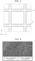
- FIG. 2 is an enlarged cross-sectional view of the direct air capture device according to the first embodiment.
- right-handed x,y,z coordinates shown in the drawings are used for the sake of convenience to describe the positional relation among component elements.
- the x,y,z coordinates in each drawing are common, and a y-axis direction is an axial direction of a porous carrier 12.
- the direct air capture device 10 includes a base 11 and the porous carrier 12. As shown in FIG. 1 , a carbon dioxide absorbent is supported on the porous carrier 12, and the direct air capture device 10 is a device that causes the porous carrier 12 to contact with air and captures carbon dioxide in the air by adsorbing the carbon dioxide to the carbon dioxide absorbent.
- the base 11 has, for example, a substantially circular columnar shape as an outer shape.
- the base 11 has a honeycomb structure made up of a plurality of channels 13 extending in the y-axis direction.
- the inner periphery of each channel 13 is coated with the porous carrier 12 on which a carbon dioxide absorbent is supported.
- each channel 13 is a square shape.
- the cross-sectional shape may be a hexagonal shape or the like.
- the outer shape of the base 11 is not limited and may be, for example, a prism shape or the like.
- the base 11 is made of, for example, an inorganic material and, specifically, made of ceramics, such as cordierite and electrically conductive silicon carbide (SiC).
- the base 11 may be made of a metal.
- the porous carrier 12 supports a carbon dioxide absorbent in micropores with, for example, a diameter of about 2 nm to about 100 nm.
- the porous carrier 12 is made of an inorganic material having a hydroxyl group and is, for example, a silica gel. Since the porous carrier 12 is porous, a surface area in which the supported carbon dioxide absorbent contacts with air increases, with the result that it is possible to adsorb carbon dioxide with high efficiency.
- the porous carrier 12 is a coating film formed on the base 11.
- the porous carrier 12 may be formed by, for example, applying a kneaded material onto the base 11.
- the kneaded material is a mixture of powder of an inorganic material (for example, a silica gel) having a hydroxyl group with an inorganic binder, such as water glass.
- an inorganic material for example, a silica gel
- an inorganic binder such as water glass.
- the carbon dioxide absorbent is a hydrophilic polymer.
- the carbon dioxide absorbent is, for example, an amine polymer, such as polyethyleneimine, primary amine, secondary amine, and secondary alkanolamine.
- a process (see FIG. 1 ) of adsorbing carbon dioxide by passing air through the direct air capture device 10 at room temperature and a process (not shown) of desorbing carbon dioxide by heating the direct air capture device 10 to, for example, about 100°C are repeatedly performed.
- the carbon dioxide absorbent degrades.
- the direct air capture device that is, the porous carrier on which the carbon dioxide absorbent is supported
- the direct air capture device 10 is periodically replaced.
- a used carbon dioxide absorbent is removed from the porous carrier 12, and the base 11 and the porous carrier 12 are reused.
- a recycling method for the direct air capture device 10 according to the present embodiment will be described later.
- the base 11 may be heated by energization.
- FIG. 3 is an enlarged cross-sectional view of the direct air capture device according to the modification of the first embodiment.
- FIG. 3 corresponds to FIG. 2 .
- the porous carrier 12 is a base having a honeycomb structure.
- the porous carrier 12 may have a honeycomb structure made up of the channels 13 extending in the y-axis direction.
- the porous carrier 12 is a base, so no coating film of a porous carrier needs to be separately formed on the base as compared to the direct air capture device 10 shown in FIG. 2 .
- a carbon dioxide absorbent is supported on the inner periphery of each channel 13 shown in FIG. 3 .
- the porous carrier 12 supports a carbon dioxide absorbent in micropores with, for example, a diameter of about 2 nm to about 100 nm.
- the porous carrier 12 is made of an inorganic material having a hydroxyl group and is, for example, a silica gel.
- a used carbon dioxide absorbent is removed from the porous carrier 12 by heating the direct air capture device 10 shown in FIG. 1 and FIG. 2 to a predetermined temperature.
- a heating temperature for removing a used carbon dioxide absorbent is higher than a heating temperature in the desorption process and is, specifically, higher than or equal to, for example, 500°C.
- the heating may be performed by heating the base 11 through energization, as in the case of the desorption process.
- the carbon dioxide absorbent made of a hydrophilic polymer dissolves as a result of heating for removing the carbon dioxide absorbent. Then, the hydroxyl group of the porous carrier 12 is lost. Therefore, the direct air capture device 10 of which the carbon dioxide absorbent is removed from the porous carrier 12 may be held in, for example, a vapor atmosphere, to recover a hydroxyl group lost from the porous carrier 12. Specifically, the direct air capture device 10 is held in a saturated vapor atmosphere at, for example, 80°C.
- a used carbon dioxide absorbent is removed from the porous carrier 12 by heating the direct air capture device 10 to a predetermined temperature, and then a new carbon dioxide absorbent is supported on the porous carrier 12.
- a new carbon dioxide absorbent is supported on the porous carrier 12.
- the recycling method for the direct air capture device 10 according to the first embodiment will be described in detail by way of Example.
- the recycling method for the direct air capture device 10 according to the first embodiment is not limited to only the following Example.
- Branched polyethyleneimine with an average molecular weight of 600 was used as a carbon dioxide absorbent.
- a 20 percent by mass polyethyleneimine solution was prepared by adding 24 g of ethanol to 6 g of polyethyleneimine.
- a bead silica gel (CARiACTQ-10 made by FUJI SILYSIA CHEMICAL, Ltd.) was put into the polyethyleneimine solution as a porous carrier, and stirred in a hermetically closed casing. After that, ethanol was removed in a reduced pressure, and then dried at 80°C.
- a silica gel is an inorganic material having a hydroxyl group
- polyethyleneimine is a hydrophilic polymer.
- polyethyleneimine that is a carbon dioxide absorbent was supported on the surface of the silica gel that is a porous carrier.
- the porous carrier corresponds to the porous carrier 12 in FIG. 2 .
- the silica gel has mesopores with a mesopore distribution of 1.1 mL/g, and polyethyleneimine is supported in the mesopores.
- FIG. 4 shows macro photograms of a bead silica gel before and after polyethyleneimine is supported.
- a silica gel is transparent, and, after polyethyleneimine is supported, the silica gel turns into white when polyethyleneimine is supported in the mesopores.
- the silica gel on which polyethyleneimine was supported was heated to the predetermined temperature and held for six hours while air was being flowed at a rate of 2L/minute.
- the heating temperature was changed, a situation in which polyethyleneimine serving as the carbon dioxide absorbent was removed was observed, and a pore distribution was measured.
- the heating temperature was set to 400°C, 450°C, and 500°C.
- FIG. 5 shows macro photographs of a silica gel after being heated to temperatures to remove polyethyleneimine.
- polyethyleneimine is heated to the predetermined temperature or higher, polyethyleneimine oxidizes to produce carbon dioxide or nitrogen dioxide, and polyethyleneimine disappears.
- the disclosure is not limited to the above-described embodiment and may be modified as needed without departing from the scope of the disclosure.
- the disclosure contributes to carbon neutral, decarbonization, and sustainable Development Goals (SDGs).
Landscapes
- Chemical & Material Sciences (AREA)
- Analytical Chemistry (AREA)
- Chemical Kinetics & Catalysis (AREA)
- Engineering & Computer Science (AREA)
- General Chemical & Material Sciences (AREA)
- Oil, Petroleum & Natural Gas (AREA)
- Organic Chemistry (AREA)
- Inorganic Chemistry (AREA)
- Physics & Mathematics (AREA)
- Thermal Sciences (AREA)
- Solid-Sorbent Or Filter-Aiding Compositions (AREA)
- Treating Waste Gases (AREA)
- Separation Of Gases By Adsorption (AREA)
- Gas Separation By Absorption (AREA)
Abstract
A recycling method for a direct air capture device is a recycling method for a direct air capture device (10) including a porous carrier (12) on which a carbon dioxide absorbent is supported. The porous carrier (12) is made of an inorganic material having a hydroxyl group. The carbon dioxide absorbent is a hydrophilic polymer. The recycling method includes removing a used carbon dioxide absorbent from the porous carrier (12) by heating the direct air capture device (10) to a predetermined temperature, and then causing a new carbon dioxide absorbent to be supported on the porous carrier (12).
Description
- The disclosure relates to a recycling method for a direct air capture device.
- To reduce carbon dioxide that is a greenhouse effect gas, there is known a direct air capture (DAC) device that directly captures carbon dioxide in air. In the direct air capture device, a carbon dioxide absorbent is supported on a porous carrier.
- As described in, for example,
Japanese Unexamined Patent Application Publication No. 2012-055886 JP 2012-055886 A - In a direct air capture device, a carbon dioxide absorbent degrades as a result of use, so the direct air capture device, that is, the porous carrier on which the carbon dioxide absorbent is supported, is periodically replaced. In contrast, the inventors have been studying recycling of a direct air capture device by removing a used carbon dioxide absorbent from a porous carrier to reuse the porous carrier.
- The disclosure provides a recycling method for a direct air capture device capable of reusing a porous carrier by removing a used carbon dioxide absorbent from the porous carrier.
- An aspect of the disclosure provides a recycling method for a direct air capture device including a porous carrier on which a carbon dioxide absorbent is supported. The porous carrier is made of an inorganic material having a hydroxyl group. The carbon dioxide absorbent is made of a hydrophilic polymer. The recycling method includes removing a used carbon dioxide absorbent from the porous carrier by heating the direct air capture device to a predetermined temperature, and then causing a new carbon dioxide absorbent to be supported on the porous carrier.
- According to the aspect of the disclosure, the porous carrier is made of an inorganic material having a hydroxyl group, the carbon dioxide absorbent is a hydrophilic polymer, and the recycling method includes removing a used carbon dioxide absorbent from the porous carrier by heating the direct air capture device to a predetermined temperature, and then causing a new carbon dioxide absorbent to be supported on the porous carrier. With this configuration, it is possible to reuse the porous carrier by removing a used carbon dioxide absorbent from the porous carrier.
- The direct air capture device may further include a base having a honeycomb structure, and the porous carrier may be a coating film formed on the base. With this configuration, it is possible to reduce the amount of use of the porous carrier. The base may be made of ceramics.
- The porous carrier may be a base having a honeycomb structure. With this configuration, no coating film of the porous carrier needs to be separately formed on the base.
- The porous carrier may be made of a silica gel. The hydrophilic polymer may be an amine polymer. The predetermined temperature may be higher than or equal to 500°C.
- The recycling method may further include removing a used carbon dioxide absorbent from the porous carrier and then holding the porous carrier in a vapor atmosphere before a new carbon dioxide absorbent is supported on the porous carrier. With this configuration, it is possible to recover a hydroxyl group lost from the porous carrier.
- According to the aspect of the disclosure, it is possible to provide a recycling method for a direct air capture device capable of reusing a porous carrier by removing a used carbon dioxide absorbent from the porous carrier.
- Features, advantages, and technical and industrial significance of exemplary embodiments of the invention will be described below with reference to the accompanying drawings, in which like signs denote like elements, and wherein:
-
FIG. 1 is a perspective view of a direct air capture device according to a first embodiment; -
FIG. 2 is an enlarged cross-sectional view of the direct air capture device according to the first embodiment; -
FIG. 3 is an enlarged cross-sectional view of a direct air capture device according to a modification of the first embodiment; -
FIG. 4 shows macro photographs of a bead silica gel before and after polyethyleneimine is supported; and -
FIG. 5 shows macro photographs of a silica gel after being heated to temperatures to remove polyethyleneimine. - Hereinafter, a specific embodiment of the disclosure will be described in detail with reference to the accompanying drawings. However, the disclosure is not limited to the following embodiment. For clear illustration, the following description and drawings are simplified as needed.
- Initially, the configuration of a direct air capture device according to a first embodiment will be described with reference to
FIG. 1 and FIG. 2. FIG. 1 is a perspective view of the direct air capture device according to the first embodiment.FIG. 2 is an enlarged cross-sectional view of the direct air capture device according to the first embodiment. Of course, right-handed x,y,z coordinates shown in the drawings are used for the sake of convenience to describe the positional relation among component elements. The x,y,z coordinates in each drawing are common, and a y-axis direction is an axial direction of aporous carrier 12. - As shown in
FIG. 2 , the directair capture device 10 includes abase 11 and theporous carrier 12. As shown inFIG. 1 , a carbon dioxide absorbent is supported on theporous carrier 12, and the directair capture device 10 is a device that causes theporous carrier 12 to contact with air and captures carbon dioxide in the air by adsorbing the carbon dioxide to the carbon dioxide absorbent. - As shown in
FIG. 1 , thebase 11 has, for example, a substantially circular columnar shape as an outer shape. As shown inFIG. 2 , thebase 11 has a honeycomb structure made up of a plurality ofchannels 13 extending in the y-axis direction. As shown inFIG. 2 , the inner periphery of eachchannel 13 is coated with theporous carrier 12 on which a carbon dioxide absorbent is supported. - As indicated by the outline arrow in
FIG. 1 , air passes in the axial direction (y-axis direction) in each of thechannels 13 coated with theporous carrier 12, and carbon dioxide in air is absorbed by the carbon dioxide absorbent supported on theporous carrier 12. InFIG. 2 , the cross-sectional shape of eachchannel 13 is a square shape. Alternatively, the cross-sectional shape may be a hexagonal shape or the like. The outer shape of thebase 11 is not limited and may be, for example, a prism shape or the like. - The
base 11 is made of, for example, an inorganic material and, specifically, made of ceramics, such as cordierite and electrically conductive silicon carbide (SiC). Thebase 11 may be made of a metal. - The
porous carrier 12 supports a carbon dioxide absorbent in micropores with, for example, a diameter of about 2 nm to about 100 nm. Theporous carrier 12 is made of an inorganic material having a hydroxyl group and is, for example, a silica gel. Since theporous carrier 12 is porous, a surface area in which the supported carbon dioxide absorbent contacts with air increases, with the result that it is possible to adsorb carbon dioxide with high efficiency. - In the present embodiment, the
porous carrier 12 is a coating film formed on thebase 11. Theporous carrier 12 may be formed by, for example, applying a kneaded material onto thebase 11. The kneaded material is a mixture of powder of an inorganic material (for example, a silica gel) having a hydroxyl group with an inorganic binder, such as water glass. In the present embodiment, since theporous carrier 12 is a coating film, it is possible to reduce the amount of use of theporous carrier 12 as compared to a modification (described later). - The carbon dioxide absorbent is a hydrophilic polymer. Specifically, the carbon dioxide absorbent is, for example, an amine polymer, such as polyethyleneimine, primary amine, secondary amine, and secondary alkanolamine.
- In capturing carbon dioxide, a process (see
FIG. 1 ) of adsorbing carbon dioxide by passing air through the directair capture device 10 at room temperature and a process (not shown) of desorbing carbon dioxide by heating the directair capture device 10 to, for example, about 100°C are repeatedly performed. When the adsorption process and the desorption process are repeated, the carbon dioxide absorbent degrades. - For this reason, in an existing direct air capture device, the direct air capture device, that is, the porous carrier on which the carbon dioxide absorbent is supported, is periodically replaced. In contrast, in the direct
air capture device 10 according to the present embodiment, a used carbon dioxide absorbent is removed from theporous carrier 12, and thebase 11 and theporous carrier 12 are reused. A recycling method for the directair capture device 10 according to the present embodiment will be described later. In the desorption process, thebase 11 may be heated by energization. - Here, the configuration of a direct air capture device according to a modification of the first embodiment will be described with reference to
FIG. 3. FIG. 3 is an enlarged cross-sectional view of the direct air capture device according to the modification of the first embodiment.FIG. 3 corresponds toFIG. 2 . - As shown in
FIG. 3 , in the directair capture device 10 according to the modification, theporous carrier 12 is a base having a honeycomb structure. In other words, theporous carrier 12 may have a honeycomb structure made up of thechannels 13 extending in the y-axis direction. In the directair capture device 10 shown inFIG. 3 , theporous carrier 12 is a base, so no coating film of a porous carrier needs to be separately formed on the base as compared to the directair capture device 10 shown inFIG. 2 . - A carbon dioxide absorbent is supported on the inner periphery of each
channel 13 shown inFIG. 3 . In the directair capture device 10 according to the modification as well, theporous carrier 12 supports a carbon dioxide absorbent in micropores with, for example, a diameter of about 2 nm to about 100 nm. Theporous carrier 12 is made of an inorganic material having a hydroxyl group and is, for example, a silica gel. - Next, a recycling method for the direct air capture device according to the present embodiment will be described. Initially, a used carbon dioxide absorbent is removed from the
porous carrier 12 by heating the directair capture device 10 shown inFIG. 1 and FIG. 2 to a predetermined temperature. A heating temperature for removing a used carbon dioxide absorbent is higher than a heating temperature in the desorption process and is, specifically, higher than or equal to, for example, 500°C. The heating may be performed by heating thebase 11 through energization, as in the case of the desorption process. - The carbon dioxide absorbent made of a hydrophilic polymer dissolves as a result of heating for removing the carbon dioxide absorbent. Then, the hydroxyl group of the
porous carrier 12 is lost. Therefore, the directair capture device 10 of which the carbon dioxide absorbent is removed from theporous carrier 12 may be held in, for example, a vapor atmosphere, to recover a hydroxyl group lost from theporous carrier 12. Specifically, the directair capture device 10 is held in a saturated vapor atmosphere at, for example, 80°C. - Subsequently, a new carbon dioxide absorbent is supported on the
porous carrier 12 from which the used carbon dioxide absorbent is removed. In this way, only the carbon dioxide absorbent is replaced and thebase 11 and theporous carrier 12 are reused, so it is possible to reduce carbon dioxide recovery cost. - As described above, with the recycling method for the direct
air capture device 10 according to the present embodiment, a used carbon dioxide absorbent is removed from theporous carrier 12 by heating the directair capture device 10 to a predetermined temperature, and then a new carbon dioxide absorbent is supported on theporous carrier 12. In other words, only the carbon dioxide absorbent is replaced and thebase 11 and theporous carrier 12 are reused, so it is possible to reduce carbon dioxide recovery cost. - Hereinafter, the recycling method for the direct
air capture device 10 according to the first embodiment will be described in detail by way of Example. However, the recycling method for the directair capture device 10 according to the first embodiment is not limited to only the following Example. - Branched polyethyleneimine with an average molecular weight of 600 (made by FUJIFILM WAKO) was used as a carbon dioxide absorbent. A 20 percent by mass polyethyleneimine solution was prepared by adding 24 g of ethanol to 6 g of polyethyleneimine. A bead silica gel (CARiACTQ-10 made by FUJI SILYSIA CHEMICAL, Ltd.) was put into the polyethyleneimine solution as a porous carrier, and stirred in a hermetically closed casing. After that, ethanol was removed in a reduced pressure, and then dried at 80°C. Here, a silica gel is an inorganic material having a hydroxyl group, and polyethyleneimine is a hydrophilic polymer.
- Through the above process, polyethyleneimine that is a carbon dioxide absorbent was supported on the surface of the silica gel that is a porous carrier. The porous carrier corresponds to the
porous carrier 12 inFIG. 2 . The silica gel has mesopores with a mesopore distribution of 1.1 mL/g, and polyethyleneimine is supported in the mesopores. - Here,
FIG. 4 shows macro photograms of a bead silica gel before and after polyethyleneimine is supported. As shown inFIG. 4 , before polyethyleneimine is supported, a silica gel is transparent, and, after polyethyleneimine is supported, the silica gel turns into white when polyethyleneimine is supported in the mesopores. - Subsequently, to remove polyethyleneimine supported on the silica gel, the silica gel on which polyethyleneimine was supported was heated to the predetermined temperature and held for six hours while air was being flowed at a rate of 2L/minute. The heating temperature was changed, a situation in which polyethyleneimine serving as the carbon dioxide absorbent was removed was observed, and a pore distribution was measured. The heating temperature was set to 400°C, 450°C, and 500°C.
-
FIG. 5 shows macro photographs of a silica gel after being heated to temperatures to remove polyethyleneimine. When polyethyleneimine is heated to the predetermined temperature or higher, polyethyleneimine oxidizes to produce carbon dioxide or nitrogen dioxide, and polyethyleneimine disappears. - As shown in
FIG. 5 , at the heating temperature of 400°C and at the heating temperature of 450°C, polyethyleneimine was partially not removed and left, and the silica gel turned into black. A pore distribution at the heating temperature of 400°C was 0.91 mL/g, and a pore distribution at the heating temperature of 450°C was 0.97 mL/g. As shown inFIG. 5 , at the heating temperature of 500°C, polyethyleneimine was sufficiently removed, and the silica gel turned into transparent again. A pore distribution at the heating temperature 500°C was 1.2 mL/g, and recovered to exceed 1.1 mL/g before use. - It is clear from the results of the above-described Example that, when a direct air capture device in which a carbon dioxide absorbent that is a hydrophilic polymer is supported on a porous carrier made of an inorganic material having a hydroxyl group is heated to 500°C or higher, the carbon dioxide absorbent is sufficiently removed and the porous carrier can be reused.
- The disclosure is not limited to the above-described embodiment and may be modified as needed without departing from the scope of the disclosure. The disclosure contributes to carbon neutral, decarbonization, and Sustainable Development Goals (SDGs).
Claims (8)
- A recycling method for a direct air capture device (10) including a porous carrier (12) on which a carbon dioxide absorbent is supported, wherein:the porous carrier (12) is made of an inorganic material having a hydroxyl group;the carbon dioxide absorbent is a hydrophilic polymer; andthe recycling method comprising removing a used carbon dioxide absorbent from the porous carrier (12) by heating the direct air capture device (10) to a predetermined temperature, and then causing a new carbon dioxide absorbent to be supported on the porous carrier (12).
- The recycling method according to claim 1, wherein:the direct air capture device (10) further includes a base (11) having a honeycomb structure; andthe porous carrier (12) is a coating film formed on the base (11).
- The recycling method according to claim 2, wherein the base (11) is made of ceramics.
- The recycling method according to claim 1, wherein the porous carrier (12) is a base (11) having a honeycomb structure.
- The recycling method according to any one of claims 1 to 4, wherein the porous carrier (12) is made of a silica gel.
- The recycling method according to any one of claims 1 to 4, wherein the hydrophilic polymer is an amine polymer.
- The recycling method according to claim 6, wherein the predetermined temperature is higher than or equal to 500°C.
- The recycling method according to any one of claims 1 to 4, further comprising removing a used carbon dioxide absorbent from the porous carrier (12) and then holding the porous carrier (12) in a vapor atmosphere before a new carbon dioxide absorbent is supported on the porous carrier (12).
Applications Claiming Priority (1)
| Application Number | Priority Date | Filing Date | Title |
|---|---|---|---|
| JP2023068431A JP7740296B2 (en) | 2023-04-19 | 2023-04-19 | How to recycle direct air recovery equipment |
Publications (1)
| Publication Number | Publication Date |
|---|---|
| EP4450145A1 true EP4450145A1 (en) | 2024-10-23 |
Family
ID=90363014
Family Applications (1)
| Application Number | Title | Priority Date | Filing Date |
|---|---|---|---|
| EP24162408.9A Pending EP4450145A1 (en) | 2023-04-19 | 2024-03-08 | Recycling method for direct air capture device |
Country Status (4)
| Country | Link |
|---|---|
| US (1) | US20240350964A1 (en) |
| EP (1) | EP4450145A1 (en) |
| JP (1) | JP7740296B2 (en) |
| CN (1) | CN118807408A (en) |
Citations (3)
| Publication number | Priority date | Publication date | Assignee | Title |
|---|---|---|---|---|
| WO2008021700A1 (en) * | 2006-08-10 | 2008-02-21 | University Of Southern California | Nano-structure supported solid regenerative polyamine and polyamine polyol absorbents for the separation of carbon dioxide from gas mixtures including the air |
| WO2017095765A1 (en) * | 2015-11-30 | 2017-06-08 | Corning Incorporated | Carbon dioxide capture articles and methods of making the same |
| CN112619627A (en) * | 2020-12-04 | 2021-04-09 | 安徽国孚凤凰科技有限公司 | Silica gel adsorbent regeneration device and method |
Family Cites Families (5)
| Publication number | Priority date | Publication date | Assignee | Title |
|---|---|---|---|---|
| US5256386A (en) * | 1987-06-29 | 1993-10-26 | Eka Nobel Ab | Method for preparation of silica particles |
| JPH04200742A (en) * | 1990-11-30 | 1992-07-21 | Kuraray Chem Corp | Carbon dioxide adsorbent |
| JP2002153718A (en) | 2000-11-16 | 2002-05-28 | Nitta Ind Corp | Gas removal filter |
| AU2010277084B2 (en) | 2009-07-27 | 2013-07-04 | Kawasaki Jukogyo Kabushiki Kaisha | Carbon Dioxide Separation Method and Apparatus |
| WO2024133317A1 (en) * | 2022-12-21 | 2024-06-27 | Basf Se | Sorbents for carbon dioxide capture |
-
2023
- 2023-04-19 JP JP2023068431A patent/JP7740296B2/en active Active
-
2024
- 2024-03-08 EP EP24162408.9A patent/EP4450145A1/en active Pending
- 2024-03-15 US US18/606,568 patent/US20240350964A1/en active Pending
- 2024-04-16 CN CN202410454885.6A patent/CN118807408A/en active Pending
Patent Citations (4)
| Publication number | Priority date | Publication date | Assignee | Title |
|---|---|---|---|---|
| WO2008021700A1 (en) * | 2006-08-10 | 2008-02-21 | University Of Southern California | Nano-structure supported solid regenerative polyamine and polyamine polyol absorbents for the separation of carbon dioxide from gas mixtures including the air |
| JP2012055886A (en) | 2006-08-10 | 2012-03-22 | Univ Of Southern California | Nano-structure supported solid regenerative polyamine and polyol absorbent for separation of carbon dioxide from gas mixture including air |
| WO2017095765A1 (en) * | 2015-11-30 | 2017-06-08 | Corning Incorporated | Carbon dioxide capture articles and methods of making the same |
| CN112619627A (en) * | 2020-12-04 | 2021-04-09 | 安徽国孚凤凰科技有限公司 | Silica gel adsorbent regeneration device and method |
Non-Patent Citations (1)
| Title |
|---|
| SANZ-PÉREZ E S ET AL: "Reuse and recycling of amine-functionalized silica materials for CO2adsorption", CHEMICAL ENGENEERING JOURNAL, ELSEVIER, AMSTERDAM, NL, vol. 308, 26 September 2016 (2016-09-26), pages 1021 - 1033, XP029805130, ISSN: 1385-8947, DOI: 10.1016/J.CEJ.2016.09.109 * |
Also Published As
| Publication number | Publication date |
|---|---|
| JP2024154557A (en) | 2024-10-31 |
| CN118807408A (en) | 2024-10-22 |
| US20240350964A1 (en) | 2024-10-24 |
| JP7740296B2 (en) | 2025-09-17 |
Similar Documents
| Publication | Publication Date | Title |
|---|---|---|
| CN103402604B (en) | Trap the product of carbon dioxide | |
| CN111801151B (en) | Acid gas absorbing material and method for producing same | |
| TW200400078A (en) | Dehumidification system and dehumidification method | |
| CA2736214A1 (en) | A sorbent and method for co2 removal utilizing an amine, a co2 activating catalyst and a porous material | |
| CN108816190B (en) | Alumina-activated carbon composite material and preparation method thereof | |
| JP2018158302A (en) | Carbon dioxide absorbing material and carbon dioxide separation recovery system | |
| TW202313184A (en) | Carbon dioxide absorbent, carbon dioxide recovery method, and carbon dioxide separation and recovery device | |
| EP4450145A1 (en) | Recycling method for direct air capture device | |
| CN119186499A (en) | Carbon dioxide trapping adsorbent, preparation method and application thereof and carbon dioxide adsorption equipment | |
| CN114713183B (en) | Flame-retardant hydrophobic porous adsorbent, preparation method and application thereof | |
| WO2010094923A2 (en) | Methods of absorption and desorption of carbon dioxide, and apparatus for each, for beneficial re-use of carbon dioxide | |
| CN103769065A (en) | Active carbon modification method for improving adsorption rate of non-polar molecules | |
| CN113209951A (en) | Monolithic structure adsorbent based on amine functionalized silica sol, preparation method and application | |
| CN108392941A (en) | The preparation method of metal mercury absorbent, the adsorbent and regeneration method | |
| US20160122186A1 (en) | Mesoporous carbon material and related methods | |
| CN108067181B (en) | Carbon monoxide highly selective absorbent and method for producing the same | |
| JP2024066759A (en) | Adsorption system and adsorption method | |
| CN117801300A (en) | A self-healing hydrogen bond organic framework material and its preparation method and application | |
| JP2023044224A (en) | Method for producing siloxane compound adsorbent, siloxane compound adsorbent, precision instrument, and coating | |
| WO2013118950A1 (en) | Method for preparing solid amine-impregnated zeolite sorbent, and sorbent prepared thereby | |
| CN114931933A (en) | Amino dynamically modified mesoporous silicon-based material and preparation method and application thereof | |
| KR20150000635A (en) | Preparation Process of Dry Adsorbent for Selective Capture of Gaseous Carbon Dioxide | |
| AU2024307549A1 (en) | Acidic gas adsorption device | |
| CN111054185B (en) | A poisonous gas adsorption device and its preparation method | |
| JP2014015369A (en) | Production method of oxidation-resistant active carbon |
Legal Events
| Date | Code | Title | Description |
|---|---|---|---|
| PUAI | Public reference made under article 153(3) epc to a published international application that has entered the european phase |
Free format text: ORIGINAL CODE: 0009012 |
|
| STAA | Information on the status of an ep patent application or granted ep patent |
Free format text: STATUS: REQUEST FOR EXAMINATION WAS MADE |
|
| 17P | Request for examination filed |
Effective date: 20240308 |
|
| AK | Designated contracting states |
Kind code of ref document: A1 Designated state(s): AL AT BE BG CH CY CZ DE DK EE ES FI FR GB GR HR HU IE IS IT LI LT LU LV MC ME MK MT NL NO PL PT RO RS SE SI SK SM TR |