EP4450110B1 - Device for infusion of pharmacologic agents and thrombus aspiration in artery - Google Patents
Device for infusion of pharmacologic agents and thrombus aspiration in artery Download PDFInfo
- Publication number
- EP4450110B1 EP4450110B1 EP24171366.8A EP24171366A EP4450110B1 EP 4450110 B1 EP4450110 B1 EP 4450110B1 EP 24171366 A EP24171366 A EP 24171366A EP 4450110 B1 EP4450110 B1 EP 4450110B1
- Authority
- EP
- European Patent Office
- Prior art keywords
- lumen
- aspiration
- catheter
- catheter assembly
- stylet
- Prior art date
- Legal status (The legal status is an assumption and is not a legal conclusion. Google has not performed a legal analysis and makes no representation as to the accuracy of the status listed.)
- Active
Links
Images



Classifications
-
- A—HUMAN NECESSITIES
- A61—MEDICAL OR VETERINARY SCIENCE; HYGIENE
- A61M—DEVICES FOR INTRODUCING MEDIA INTO, OR ONTO, THE BODY; DEVICES FOR TRANSDUCING BODY MEDIA OR FOR TAKING MEDIA FROM THE BODY; DEVICES FOR PRODUCING OR ENDING SLEEP OR STUPOR
- A61M25/00—Catheters; Hollow probes
- A61M25/01—Introducing, guiding, advancing, emplacing or holding catheters
- A61M25/0102—Insertion or introduction using an inner stiffening member, e.g. stylet or push-rod
-
- A—HUMAN NECESSITIES
- A61—MEDICAL OR VETERINARY SCIENCE; HYGIENE
- A61B—DIAGNOSIS; SURGERY; IDENTIFICATION
- A61B17/00—Surgical instruments, devices or methods
- A61B17/22—Implements for squeezing-off ulcers or the like on inner organs of the body; Implements for scraping-out cavities of body organs, e.g. bones; for invasive removal or destruction of calculus using mechanical vibrations; for removing obstructions in blood vessels, not otherwise provided for
-
- A—HUMAN NECESSITIES
- A61—MEDICAL OR VETERINARY SCIENCE; HYGIENE
- A61M—DEVICES FOR INTRODUCING MEDIA INTO, OR ONTO, THE BODY; DEVICES FOR TRANSDUCING BODY MEDIA OR FOR TAKING MEDIA FROM THE BODY; DEVICES FOR PRODUCING OR ENDING SLEEP OR STUPOR
- A61M25/00—Catheters; Hollow probes
- A61M25/0021—Catheters; Hollow probes characterised by the form of the tubing
- A61M25/0023—Catheters; Hollow probes characterised by the form of the tubing by the form of the lumen, e.g. cross-section, variable diameter
- A61M25/0026—Multi-lumen catheters with stationary elements
-
- A—HUMAN NECESSITIES
- A61—MEDICAL OR VETERINARY SCIENCE; HYGIENE
- A61M—DEVICES FOR INTRODUCING MEDIA INTO, OR ONTO, THE BODY; DEVICES FOR TRANSDUCING BODY MEDIA OR FOR TAKING MEDIA FROM THE BODY; DEVICES FOR PRODUCING OR ENDING SLEEP OR STUPOR
- A61M25/00—Catheters; Hollow probes
- A61M25/0067—Catheters; Hollow probes characterised by the distal end, e.g. tips
- A61M25/0068—Static characteristics of the catheter tip, e.g. shape, atraumatic tip, curved tip or tip structure
- A61M25/007—Side holes, e.g. their profiles or arrangements; Provisions to keep side holes unblocked
-
- A—HUMAN NECESSITIES
- A61—MEDICAL OR VETERINARY SCIENCE; HYGIENE
- A61M—DEVICES FOR INTRODUCING MEDIA INTO, OR ONTO, THE BODY; DEVICES FOR TRANSDUCING BODY MEDIA OR FOR TAKING MEDIA FROM THE BODY; DEVICES FOR PRODUCING OR ENDING SLEEP OR STUPOR
- A61M25/00—Catheters; Hollow probes
- A61M25/0097—Catheters; Hollow probes characterised by the hub
-
- A—HUMAN NECESSITIES
- A61—MEDICAL OR VETERINARY SCIENCE; HYGIENE
- A61M—DEVICES FOR INTRODUCING MEDIA INTO, OR ONTO, THE BODY; DEVICES FOR TRANSDUCING BODY MEDIA OR FOR TAKING MEDIA FROM THE BODY; DEVICES FOR PRODUCING OR ENDING SLEEP OR STUPOR
- A61M25/00—Catheters; Hollow probes
- A61M25/01—Introducing, guiding, advancing, emplacing or holding catheters
- A61M25/0105—Steering means as part of the catheter or advancing means; Markers for positioning
-
- A—HUMAN NECESSITIES
- A61—MEDICAL OR VETERINARY SCIENCE; HYGIENE
- A61M—DEVICES FOR INTRODUCING MEDIA INTO, OR ONTO, THE BODY; DEVICES FOR TRANSDUCING BODY MEDIA OR FOR TAKING MEDIA FROM THE BODY; DEVICES FOR PRODUCING OR ENDING SLEEP OR STUPOR
- A61M25/00—Catheters; Hollow probes
- A61M25/01—Introducing, guiding, advancing, emplacing or holding catheters
- A61M25/0105—Steering means as part of the catheter or advancing means; Markers for positioning
- A61M25/0108—Steering means as part of the catheter or advancing means; Markers for positioning using radio-opaque or ultrasound markers
-
- A—HUMAN NECESSITIES
- A61—MEDICAL OR VETERINARY SCIENCE; HYGIENE
- A61M—DEVICES FOR INTRODUCING MEDIA INTO, OR ONTO, THE BODY; DEVICES FOR TRANSDUCING BODY MEDIA OR FOR TAKING MEDIA FROM THE BODY; DEVICES FOR PRODUCING OR ENDING SLEEP OR STUPOR
- A61M25/00—Catheters; Hollow probes
- A61M25/10—Balloon catheters
-
- A—HUMAN NECESSITIES
- A61—MEDICAL OR VETERINARY SCIENCE; HYGIENE
- A61M—DEVICES FOR INTRODUCING MEDIA INTO, OR ONTO, THE BODY; DEVICES FOR TRANSDUCING BODY MEDIA OR FOR TAKING MEDIA FROM THE BODY; DEVICES FOR PRODUCING OR ENDING SLEEP OR STUPOR
- A61M39/00—Tubes, tube connectors, tube couplings, valves, access sites or the like, specially adapted for medical use
- A61M39/22—Valves or arrangement of valves
- A61M39/223—Multiway valves
-
- A—HUMAN NECESSITIES
- A61—MEDICAL OR VETERINARY SCIENCE; HYGIENE
- A61B—DIAGNOSIS; SURGERY; IDENTIFICATION
- A61B17/00—Surgical instruments, devices or methods
- A61B17/22—Implements for squeezing-off ulcers or the like on inner organs of the body; Implements for scraping-out cavities of body organs, e.g. bones; for invasive removal or destruction of calculus using mechanical vibrations; for removing obstructions in blood vessels, not otherwise provided for
- A61B2017/22038—Implements for squeezing-off ulcers or the like on inner organs of the body; Implements for scraping-out cavities of body organs, e.g. bones; for invasive removal or destruction of calculus using mechanical vibrations; for removing obstructions in blood vessels, not otherwise provided for with a guide wire
-
- A—HUMAN NECESSITIES
- A61—MEDICAL OR VETERINARY SCIENCE; HYGIENE
- A61B—DIAGNOSIS; SURGERY; IDENTIFICATION
- A61B17/00—Surgical instruments, devices or methods
- A61B17/22—Implements for squeezing-off ulcers or the like on inner organs of the body; Implements for scraping-out cavities of body organs, e.g. bones; for invasive removal or destruction of calculus using mechanical vibrations; for removing obstructions in blood vessels, not otherwise provided for
- A61B2017/22051—Implements for squeezing-off ulcers or the like on inner organs of the body; Implements for scraping-out cavities of body organs, e.g. bones; for invasive removal or destruction of calculus using mechanical vibrations; for removing obstructions in blood vessels, not otherwise provided for with an inflatable part, e.g. balloon, for positioning, blocking, or immobilisation
-
- A—HUMAN NECESSITIES
- A61—MEDICAL OR VETERINARY SCIENCE; HYGIENE
- A61B—DIAGNOSIS; SURGERY; IDENTIFICATION
- A61B17/00—Surgical instruments, devices or methods
- A61B17/22—Implements for squeezing-off ulcers or the like on inner organs of the body; Implements for scraping-out cavities of body organs, e.g. bones; for invasive removal or destruction of calculus using mechanical vibrations; for removing obstructions in blood vessels, not otherwise provided for
- A61B2017/22051—Implements for squeezing-off ulcers or the like on inner organs of the body; Implements for scraping-out cavities of body organs, e.g. bones; for invasive removal or destruction of calculus using mechanical vibrations; for removing obstructions in blood vessels, not otherwise provided for with an inflatable part, e.g. balloon, for positioning, blocking, or immobilisation
- A61B2017/22062—Implements for squeezing-off ulcers or the like on inner organs of the body; Implements for scraping-out cavities of body organs, e.g. bones; for invasive removal or destruction of calculus using mechanical vibrations; for removing obstructions in blood vessels, not otherwise provided for with an inflatable part, e.g. balloon, for positioning, blocking, or immobilisation to be filled with liquid
-
- A—HUMAN NECESSITIES
- A61—MEDICAL OR VETERINARY SCIENCE; HYGIENE
- A61B—DIAGNOSIS; SURGERY; IDENTIFICATION
- A61B17/00—Surgical instruments, devices or methods
- A61B17/22—Implements for squeezing-off ulcers or the like on inner organs of the body; Implements for scraping-out cavities of body organs, e.g. bones; for invasive removal or destruction of calculus using mechanical vibrations; for removing obstructions in blood vessels, not otherwise provided for
- A61B2017/22051—Implements for squeezing-off ulcers or the like on inner organs of the body; Implements for scraping-out cavities of body organs, e.g. bones; for invasive removal or destruction of calculus using mechanical vibrations; for removing obstructions in blood vessels, not otherwise provided for with an inflatable part, e.g. balloon, for positioning, blocking, or immobilisation
- A61B2017/22065—Functions of balloons
- A61B2017/22067—Blocking; Occlusion
-
- A—HUMAN NECESSITIES
- A61—MEDICAL OR VETERINARY SCIENCE; HYGIENE
- A61B—DIAGNOSIS; SURGERY; IDENTIFICATION
- A61B17/00—Surgical instruments, devices or methods
- A61B17/22—Implements for squeezing-off ulcers or the like on inner organs of the body; Implements for scraping-out cavities of body organs, e.g. bones; for invasive removal or destruction of calculus using mechanical vibrations; for removing obstructions in blood vessels, not otherwise provided for
- A61B2017/22079—Implements for squeezing-off ulcers or the like on inner organs of the body; Implements for scraping-out cavities of body organs, e.g. bones; for invasive removal or destruction of calculus using mechanical vibrations; for removing obstructions in blood vessels, not otherwise provided for with suction of debris
-
- A—HUMAN NECESSITIES
- A61—MEDICAL OR VETERINARY SCIENCE; HYGIENE
- A61B—DIAGNOSIS; SURGERY; IDENTIFICATION
- A61B17/00—Surgical instruments, devices or methods
- A61B17/22—Implements for squeezing-off ulcers or the like on inner organs of the body; Implements for scraping-out cavities of body organs, e.g. bones; for invasive removal or destruction of calculus using mechanical vibrations; for removing obstructions in blood vessels, not otherwise provided for
- A61B2017/22082—Implements for squeezing-off ulcers or the like on inner organs of the body; Implements for scraping-out cavities of body organs, e.g. bones; for invasive removal or destruction of calculus using mechanical vibrations; for removing obstructions in blood vessels, not otherwise provided for after introduction of a substance
-
- A—HUMAN NECESSITIES
- A61—MEDICAL OR VETERINARY SCIENCE; HYGIENE
- A61B—DIAGNOSIS; SURGERY; IDENTIFICATION
- A61B17/00—Surgical instruments, devices or methods
- A61B17/22—Implements for squeezing-off ulcers or the like on inner organs of the body; Implements for scraping-out cavities of body organs, e.g. bones; for invasive removal or destruction of calculus using mechanical vibrations; for removing obstructions in blood vessels, not otherwise provided for
- A61B2017/22082—Implements for squeezing-off ulcers or the like on inner organs of the body; Implements for scraping-out cavities of body organs, e.g. bones; for invasive removal or destruction of calculus using mechanical vibrations; for removing obstructions in blood vessels, not otherwise provided for after introduction of a substance
- A61B2017/22084—Implements for squeezing-off ulcers or the like on inner organs of the body; Implements for scraping-out cavities of body organs, e.g. bones; for invasive removal or destruction of calculus using mechanical vibrations; for removing obstructions in blood vessels, not otherwise provided for after introduction of a substance stone- or thrombus-dissolving
-
- A—HUMAN NECESSITIES
- A61—MEDICAL OR VETERINARY SCIENCE; HYGIENE
- A61B—DIAGNOSIS; SURGERY; IDENTIFICATION
- A61B17/00—Surgical instruments, devices or methods
- A61B17/22—Implements for squeezing-off ulcers or the like on inner organs of the body; Implements for scraping-out cavities of body organs, e.g. bones; for invasive removal or destruction of calculus using mechanical vibrations; for removing obstructions in blood vessels, not otherwise provided for
- A61B2017/22094—Implements for squeezing-off ulcers or the like on inner organs of the body; Implements for scraping-out cavities of body organs, e.g. bones; for invasive removal or destruction of calculus using mechanical vibrations; for removing obstructions in blood vessels, not otherwise provided for for crossing total occlusions, i.e. piercing
-
- A—HUMAN NECESSITIES
- A61—MEDICAL OR VETERINARY SCIENCE; HYGIENE
- A61B—DIAGNOSIS; SURGERY; IDENTIFICATION
- A61B90/00—Instruments, implements or accessories specially adapted for surgery or diagnosis and not covered by any of the groups A61B1/00 - A61B50/00, e.g. for luxation treatment or for protecting wound edges
- A61B90/39—Markers, e.g. radio-opaque or breast lesions markers
- A61B2090/3966—Radiopaque markers visible in an X-ray image
-
- A—HUMAN NECESSITIES
- A61—MEDICAL OR VETERINARY SCIENCE; HYGIENE
- A61B—DIAGNOSIS; SURGERY; IDENTIFICATION
- A61B2217/00—General characteristics of surgical instruments
- A61B2217/002—Auxiliary appliance
- A61B2217/005—Auxiliary appliance with suction drainage system
-
- A—HUMAN NECESSITIES
- A61—MEDICAL OR VETERINARY SCIENCE; HYGIENE
- A61M—DEVICES FOR INTRODUCING MEDIA INTO, OR ONTO, THE BODY; DEVICES FOR TRANSDUCING BODY MEDIA OR FOR TAKING MEDIA FROM THE BODY; DEVICES FOR PRODUCING OR ENDING SLEEP OR STUPOR
- A61M25/00—Catheters; Hollow probes
- A61M25/0021—Catheters; Hollow probes characterised by the form of the tubing
- A61M25/0023—Catheters; Hollow probes characterised by the form of the tubing by the form of the lumen, e.g. cross-section, variable diameter
- A61M25/0026—Multi-lumen catheters with stationary elements
- A61M25/003—Multi-lumen catheters with stationary elements characterized by features relating to least one lumen located at the distal part of the catheter, e.g. filters, plugs or valves
- A61M2025/0031—Multi-lumen catheters with stationary elements characterized by features relating to least one lumen located at the distal part of the catheter, e.g. filters, plugs or valves characterized by lumina for withdrawing or delivering, i.e. used for extracorporeal circuit treatment
-
- A—HUMAN NECESSITIES
- A61—MEDICAL OR VETERINARY SCIENCE; HYGIENE
- A61M—DEVICES FOR INTRODUCING MEDIA INTO, OR ONTO, THE BODY; DEVICES FOR TRANSDUCING BODY MEDIA OR FOR TAKING MEDIA FROM THE BODY; DEVICES FOR PRODUCING OR ENDING SLEEP OR STUPOR
- A61M25/00—Catheters; Hollow probes
- A61M25/0067—Catheters; Hollow probes characterised by the distal end, e.g. tips
- A61M25/0082—Catheter tip comprising a tool
- A61M25/0084—Catheter tip comprising a tool being one or more injection needles
- A61M2025/0089—Single injection needle protruding axially, i.e. along the longitudinal axis of the catheter, from the distal tip
-
- A—HUMAN NECESSITIES
- A61—MEDICAL OR VETERINARY SCIENCE; HYGIENE
- A61M—DEVICES FOR INTRODUCING MEDIA INTO, OR ONTO, THE BODY; DEVICES FOR TRANSDUCING BODY MEDIA OR FOR TAKING MEDIA FROM THE BODY; DEVICES FOR PRODUCING OR ENDING SLEEP OR STUPOR
- A61M25/00—Catheters; Hollow probes
- A61M25/10—Balloon catheters
- A61M2025/1043—Balloon catheters with special features or adapted for special applications
- A61M2025/1052—Balloon catheters with special features or adapted for special applications for temporarily occluding a vessel for isolating a sector
-
- A—HUMAN NECESSITIES
- A61—MEDICAL OR VETERINARY SCIENCE; HYGIENE
- A61M—DEVICES FOR INTRODUCING MEDIA INTO, OR ONTO, THE BODY; DEVICES FOR TRANSDUCING BODY MEDIA OR FOR TAKING MEDIA FROM THE BODY; DEVICES FOR PRODUCING OR ENDING SLEEP OR STUPOR
- A61M39/00—Tubes, tube connectors, tube couplings, valves, access sites or the like, specially adapted for medical use
- A61M39/22—Valves or arrangement of valves
- A61M2039/229—Stopcocks
Definitions
- the present application pertains to a catheter assembly for the infusion of pharmacologic agents and thrombus aspiration in atherosclerotic vascular disease.
- the present disclosure provides also a non-claimed method for infusing pharmacologic agents and/ or performing thrombus aspiration in artherosclerotic vascular disease.
- a catheter assembly comprising a distal shaft having a guide lumen and an infusion lumen; a proximal shaft connected to the distal shaft, the proximal shaft defining an aspiration lumen opening at or near the distal shaft, and an inflating lumen; an inflatable member at a distal end of the inflating lumen, the inflatable member configured to inflate upon receiving a fluid from the inflating lumen; a stylet tube extending along the aspiration lumen and in fluid communication with the infusion lumen, the stylet tube configured to supply the infusion lumen with a pharmacologic agent; wherein the catheter assembly is configured to be displaced percutaneously in an artery by the guide lumen moving along a guide wire.
- a catheter hub may be at a proximal end of the proximal shaft.
- the catheter hub is in fluid communication with the stylet tube, with the aspiration lumen and with the inflating lumen.
- a three-way valve may be on the port dedicated to the inflating lumen.
- radio-opaque markers may be provide dat or near opposed ends of the infusion lumen.
- the stylet is removable from the aspiration lumen prior to aspiration.
- the distal shaft has an aspiration port in fluid communication with the aspiration lumen.
- a guide wire may be part of the catheter assembly.
- a method for treating an artery having a thrombus comprising: percutaneously positioning a guide wire into an artery toward the thrombus; moving a distal shaft of a catheter along the guide wire until a tip of an infusion lumen of the distal shaft passes through the thrombus to a distal location, while an inflatable member and an aspiration lumen extending into a proximal shaft of the catheter are proximal to the thrombus; and infusing at least one pharmacologic agent distally to the thrombus via the infusion lumen.
- inflating the inflatable member may occur proximally to the thrombus.
- proximally may refer to positions upstream of a thrombus relative to blood flow
- distal may refer to positions downstream of a thrombus relative to blood flow.
- inflating the inflatable member proximally to the thrombus is performed prior to infusing at least one pharmacologic agent distally to the thrombus.
- positioning the catheter and passing of the tip are done by moving the catheter over a guide wire.
- infusing at least one pharmacologic agent includes infusing the pharmacologic agent in a tube of a stylet extending to the infusion lumen.
- infusing the pharmacologic agent in a tube of a stylet extending to the infusion lumen includes infusing the pharmacologic agent in the tube of the stylet passing through the aspiration lumen.
- a catheter assembly in accordance with the present disclosure is generally shown at 10.
- the catheter assembly 10 may be used for the infusion of pharmacologic agents and for thrombus aspiration in accordance with the methodology described for method 70 of Fig. 7 as described hereinafter, through the method 70 and the catheter assembly 10 may not be mutually exclusive.
- the method 70 may be used with a catheter assembly differing the catheter assembly 10
- the catheter assembly 10 may be used with a method differing from the method 70 of Fig. 7 .
- the catheter assembly 10 is introduced over a guide wire 11 that is inserted into any appropriate vessel of the vascular system, such as the coronary artery, with a view to attend to a thrombus.
- the catheter assembly 10 has a hydrophilic surface, so as to slide within the artery with reduced invasiveness.
- the catheter assembly 10 may have one or more of the guide wire 11, though the guide wire 11 may be an add-on that is not part of the catheter assembly 10, a proximal shaft 20, a distal shaft 30, a catheter hub 40, and/or a stylet 50, though the stylet 50 may not be part of the catheter assembly 10.
- Other components may be part of the catheter assembly 10, such as any of those described herein through Figs. 8A-11 .
- the guide wire 11 is the guide upon which parts of the catheter assembly 10 will be slid or guided in order to reach a target zone.
- the catheter assembly 10 includes the proximal shaft 20, the distal shaft 30 and/or may include the catheter hub 40. It may also be said that the guide wire 11 may be part of the catheter.
- the proximal shaft 20 is between the distal shaft 30 and the catheter hub 40, and serves as a canal for fluid displacement (and possibly solids), among other functions, in a distal direction and/or proximal direction.
- the proximal shaft 20 may be the longest component of the catheter (e.g. depending on whether the guide wire 11 is part or not of the catheter).
- Figs. 1 and 2 are schematic views and may not be representative of the length of the proximal shaft 20 relative to the distal shaft 30 and catheter hub 40.
- the distal shaft 30 is at the distal end of the proximal shaft 20 and may be one of the output ends of the catheter.
- the catheter hub 40 may be located outside of the body during a procedure, while the proximal shaft 20 is mostly in the body - it may gradually be inserted into the body -, and the distal shaft 30 is within the body.
- the catheter hub 40 is the interface that may be manipulated by an operator, to perform infusion, inflating and aspiration, for example.
- the stylet 50 may be used in the infusion of a pharmacologic agent in the human body, and may also be referred to as a tube.
- the stylet 50 provides some rigidity to the catheter assembly 10, and may be optionally used to transmit a push force when positioning the catheter device in the vessel.
- the stylet 50 is a one-time use device.
- the proximal shaft 20 is shown as having an elongated body, that is merely shown schematically but that may be substantially longer than what is shown in Figs. 1 and 2 .
- the proximal shaft 20 may have a monoblock body, for instance that may be extruded. Other constructions include a combination of materials, braiding, etc.
- the proximal shaft 20 may include an outer sheath that incorporates therein different tubes that may define different lumens, as described below, or may be monoblock and define one or more of these lumens.
- the proximal shaft 20 may also have different constructions, such as by forming an outer jacket supporting different tubes, that will define different types of lumens. The following description pertains to a monoblock body for the shaft portion of the proximal shaft 20, though other types of constructions are considered, and are suggested as well where applicable.
- the inflating lumen 22 may have an inner diameter of 0.018", though this is merely given as an example.
- a typical inner diameter of the inflating lumen 22 ranges from 0.001 to 0.038". (0.025 to 0.97 mm)
- the inflating tube may have a wall thickness of 0.0020" (0.051 mm) and an outer diameter of 0.022" (0.56 mm), again with these values merely provided as examples. Other dimensions are considered as well.
- Any appropriate type of fluid may be used. For instance, a mixture of saline and iodine contrast is commonly used for inflating balloons in percutaneous coronary intervention.
- the fluid used to inflate an inflatable member may have suitable contrast to be detected via radiographic imaging.
- the distal shaft 30 is shown as having a body tapering from a proximal end toward a distal end, to facilitate its displacement in a vessel.
- the distal shaft 30 may also have a monoblock body, for instance that may be extruded, but this is only an option as the distal shaft 30 may be constituted of more than one component.
- the distal shaft 30 may also have different constructions, such as by forming an outer jacket supporting different tubes, that will define different types of lumens.
- the distal shaft 30 may have an aspiration port 30A.
- the aspiration lumen 21 in the proximal shaft 20 is in fluid communication with the body of the distal shaft 30 and thus with the aspiration portion 30A, with the aspiration port 30A opening into the vessel.
- the aspiration port 30A may be a suction port of the catheter.
- the distal shaft 30 may then taper to form a smaller cross-section that may be passed through a thrombus.
- the aspiration lumen 21 in the proximal shaft 20 opens directly into the vessel, such that the distal shaft 30 is not part of the aspiration step.
- the distal shaft 30 also has an infusion lumen 31, that is used to deliver the pharmacologic agent at the distal end of the catheter.
- the infusion lumen 31 may be a passage of the stylet 50, or may be in fluid communication with the distal end of the stylet 50 so as to receive the pharmacological agent and deliver same to the infusion target site.
- the infusion lumen 31 may have a funneling geometry in a distal direction. In Fig. 6 , this scenario is shown, i.e., the stylet 50 is fluidly connected to the infusion lumen 31, for the pharmacologic agent to travel through the infusion lumen 31 and out of the distal tip of the distal shaft 30.
- the funnel geometry of the infusion lumen 31 is optional, but is well suited to ensure that the stylet 50 is in fluid communication with and delivers its pharmacologic agent to the infusion lumen 31.
- the distal shaft 30 further includes a guide lumen 32 configured to be mounted onto the guide wire 11, for relative movement between the guide wire 11 and the distal shaft 30.
- the guide lumen 32 opens at the distal end of the distal shaft 30.
- the guide lumen 32 ends at or near the proximal end of the distal shaft 30, though it may also extend to part of the proximal shaft 20, at an exit port 33.
- the guide lumen 32 has a length of about 6 inches ⁇ 2 inches (about 15 cm ⁇ 5 cm).
- the catheter may only have its distal shaft 30 mounted to the guide wire 11, thereby limiting friction, and facilitating displacement.
- the catheter may slide along the guide wire 11 during its insertion in the vessel.
- Markers 34 of detectable material may be provided at one or both extremities of the distal shaft 30 for localization thereof, such as at the distal tip of infusion lumen 31.
- radio-opaque material may be used for fluoroscopic localization, such as platinum with an iridium content (e.g., 10%).
- the markers 34 have an inner diameter of 0.023" (0.58 mm), a wall of 0.001" (0,025 mm) and an outside diameter of 0.025" (0.63 mm). These values are merely provided as examples.
- the branch portion 40B may define the inflating port 42, and may thus be in fluid communication with the inflating lumen 22, so as to direct fluid into the inflatable member 23.
- the flush portion 41 may optionally be provided with a valve 43 to control the suction effect.
- the valve 43 is not part of the catheter assembly 10.
- the stylet 50 is fitted into the catheter via the central tubular portion 40A, though other arrangements are connected.
- Collets 44 may be provided to interconnect the hub 40 with the proximal shaft 20, the collets 44 contributing to maintaining the fluid communication between components, as described above.
- the tubes associated with the lumens 21 and/or 22, and the stylet 50 may be equipped with suitable connectors (e.g., luers) for connection to the various devices (e.g., syringe).
- suitable connectors e.g., luers
- one such connector is shown at 51 at the distal end of the stylet 50.
- the stylet 50 may thus be connected to a source of pharmacologic agents, such as a syringe, etc, for the controlled infusion of pharmacologic agents passing through the catheter of the catheter assembly 10.
- the inflating lumen 22 is connected to a source of fluid for pressurization of the inflatable member 23.
- the catheter hub 40 may have a central tubular portion 40A with a branch portion 40B diverging from the central tubular portion 40A, and another branch portion 40C also diverging from the central tubular portion 40A.
- the central tubular portion 40A defines at its proximal end the injection port, or at the proximal end of part 40A1.
- the branch portion 40B may define the inflating port 42, and may thus be in fluid communication with the inflating lumen 22, so as to direct fluid into the inflatable member 23.
- the branch portion 40C may be the flush port 41 through which suction will be exerted on the catheter, during aspiration.
- Collet 44 may be provided to interconnect the part 40A1 of the hub 40 featuring the branch portion 40B with the part 40A2 of the hub featuring the branch portion 40C.
- the stylet 50 may be accessed when separating part 40A1 from part 40A2, as an example.
- Other collets may be present, such as to connect the central tubular portion 40A to the proximal shaft 20, for example.
- the collet 44 contributes to maintaining the fluid communication between components, as described above.
- the tubes associated with the lumens 21 and/or 22, and the stylet 50 may be equipped with suitable connectors (e.g., luers) for connection to the various devices (e.g., syringe).
- the aspiration lumen 21, such as through the flush portion 41, is connected to an aspiration mechanism, such as a vacuuming syringe or the like. Accordingly, an aspiration action performed at the external end of the catheter causes an aspiration at the open internal end of the aspiration lumen 21 (e.g., aspiration port 30A), such as at the distal end of the proximal shaft 20 or at an outlet end within the distal shaft 30.
- the open internal end of the aspiration lumen 21 is positioned adjacent to the blood clot in the thrombus aspiration application, the blood clot is vacuumed away from the artery via the aspiration lumen 21.
- the tubes and/or the stylet 50 is/are, for instance, made of polyimide of medical grade, or any other relatively compliant material.
- One material that may be used for the shafts 20 and/or 30 and/or stylet 50 is braided reinforced polyimide, to ensure that the aspiration lumen 21 retains its structurally integrity despite the vacuuming pressure, and to maintain the shape during insertion in the vessel, to avoid kinking.
- an outer jacket making up the external body of the proximal shaft 20 may be slid over the tubes that would define the aspiration lumen 21 and/or the inflating lumen 22. With tubes fixed and aligned with an outer jacket thereon, the assembly may be passed through a heated die, with the outer jacket fusing all together. Hence, these components are integrally connected to one another, if not monoblock.
- a distal end of the guide wire 11 is percutaneously inserted onto a blood vessel (e.g., coronary artery), and is moved up to the thrombus.
- a blood vessel e.g., coronary artery
- the guide wire 11 is moved through the thrombus.
- a proximal end of the guide wire 11 may be out of the body.
- the catheter of the catheter assembly 10 is percutaneously inserted into the vessel proximally of the occlusion, to be directed distally in the vessel toward the thrombus, as being guided onto the guide wire 11.
- the distal shaft 30 that is mounted onto the guide wire 11 outside of the body, via the guide lumen 32, to then be inserted into the vessel as slid along the guide wire 11.
- the stylet 50 may be used to push the catheter into position, the stylet 50 having been assembled prior to step 72 (for example, as assembled), the stylet 50 being in fluid communication with the infusion lumen 31. It may also be possible to insert the stylet 50 after the combination of the distal shaft 30 and proximal shaft 20 have being guided to the thrombus by moving onto the guide wire 11.
- an inflatable member on the catheter assembly is inflated proximally of the blood clot. If the catheter assembly 10 is used, the inflatable member 23 is inflated via the inflating lumen 22.
- a pharmacologic agent e.g., adenosine
- a pharmacologic agent e.g., adenosine
- the infusion is performed via the stylet 50, that has been inserted into the proximal shaft 20. It may be required that the stylet 50 be slid into the aspiration lumen 21 and displaced in a distal direction, until the distal tip of the stylet 50 reaches the infusion lumen 31.
- the blood clot is vacuumed out of the artery so as to open the artery.
- the aspiration lumen 21 of the catheter assembly 10 is distally positioned relative to the inflatable member 23, such that the inflatable member 23 may not interfere with the vacuuming.
- the stylet 50 is removed from the aspiration lumen 21, prior to the vacuuming.
- the aspiration lumen 21 may serve as aspiration passage and as passage for the stylet 50 for the pharmacologic agent.
- the aspiration lumen 21 may serve for fluid movement in a distal direction, and in proximal direction. This may be simultaneous and/or sequential.
- the aspiration is initiated while the inflatable member 23 is inflated. This causes a relative negative pressure between the tip of the aspiration lumen 21 or suction portion 30A and the thrombus.
- the aspiration may also be initiated after deflation of the inflatable member 23. The deflation may also occur during the aspiration.
- the syringe 80 may have its plunger partially or fully depressed to the proximal port of the three-way valve 43. Referring to Fig. 8C , the plunger of the syringe 80 may be pulled, and while maintaining the plunger in place, the valve 43 may be turned counter-clockwise to put the distal port in the OFF position thereby creating a vacuum inside the balloon 23. The syringe 80 may be detached after use.
- the catheter may be used with balloon inflation accessories.
- the balloon inflation accessories may be set up by connecting the syringe 80 filled with a liquid, such as at least 5 mL of a 50:50 v/v saline-contrast mixture (as an example among others), to the proximal port of the three-way valve 43 and depressing the plunger of the syringe 80 to purge air out of the vertical port of the three-way valve 43.
- Another syringe 81 such as one with a lesser volume, may also be filled with a fluid, such as 50:50 v/v saline-contrast mixture (as an example) to the vertical port of the three-way valve 43.
- the aspiration catheter assembly may be used with aspiration accessories.
- the aspiration accessories may be primed by attaching an extension tube to an aspiration syringe containing 5 to 10 mL of heparinized saline, the extension tube having a stopcock that can be placed in an open position to flush the entire length of the extension tube; the stopcock may be closed after flushing and the plunger of the aspiration syringe may be pulled until reaching its full extension before being locked in place.
- the stylet 50 may be removed. In a variant, this is achieved by removing the part of the catheter hub 40 including the branch portion 40C, thereby liberating the aspiration lumen 21 ( Figs. 4 and 5 )
- the catheter assembly comprises a distal shaft having a guide lumen and an infusion lumen; a proximal shaft connected to the distal shaft, the proximal shaft defining an aspiration lumen opening at or near the distal shaft, and an inflating lumen; an inflatable member at a distal end of the inflating lumen, the inflatable member configured to inflate upon receiving a fluid from the inflating lumen; a stylet tube extending along the aspiration lumen and in fluid communication with the infusion lumen, the stylet tube configured to supply the infusion lumen with a pharmacologic agent; wherein the catheter assembly is configured to be displaced percutaneously in an artery by the guide lumen moving along a guide wire.
- pharmacologic agents may be used for the infusion, the doses of which are selected on a case-by-case basis by appropriate personnel.
- pharmacologic agents that can be used are: adenosine and adenosine receptor agonists, beta blockers, angiotensin-converting enzyme inhibitor, angiotensin-receptor blockers, aldosterone, calcium channel blockers (Verapamil, Diltiazem, Nifedipine), cyclosporin, calpain inhibitor, sodium-proton exchanger inhibitor, NO donor, cox-2 inhibitor, statins, TNF-alpha, endothelin receptor antagonists, antiplatelet, antithrombotic, erythropoietin, anti-leukocyte complement inhibitors, opioid, anesthetic, K ATP "openers", insulin, thrombin and fragments, melatonin, H 2 S, bradykinin, cellular therapy, gene therapy, with the proper catheter.
Landscapes
- Health & Medical Sciences (AREA)
- Life Sciences & Earth Sciences (AREA)
- Heart & Thoracic Surgery (AREA)
- Public Health (AREA)
- Biomedical Technology (AREA)
- Engineering & Computer Science (AREA)
- Animal Behavior & Ethology (AREA)
- General Health & Medical Sciences (AREA)
- Veterinary Medicine (AREA)
- Anesthesiology (AREA)
- Hematology (AREA)
- Pulmonology (AREA)
- Biophysics (AREA)
- Surgery (AREA)
- Nuclear Medicine, Radiotherapy & Molecular Imaging (AREA)
- Vascular Medicine (AREA)
- Orthopedic Medicine & Surgery (AREA)
- Medical Informatics (AREA)
- Molecular Biology (AREA)
- Child & Adolescent Psychology (AREA)
- Media Introduction/Drainage Providing Device (AREA)
Description
- The present application pertains to a catheter assembly for the infusion of pharmacologic agents and thrombus aspiration in atherosclerotic vascular disease.
- A prevalent cause of adult mortality in developed countries is atherosclerotic vascular disease.
- For example, occlusion of a coronary artery subsequent to a plaque rupture remains one of the most frequent causes of myocardial infarction.
- To treat such ailment, percutaneous coronary intervention is an efficient reperfusion method when performed promptly. Yet, the opening of coronary arteries is an invasive and risky procedure. Despite efficient and prompt intervention, some patients will present a condition known as no-reflow in which, in spite of the fact that the coronary artery is opened without residual stenosis, myocardial perfusion is diminished. No-reflow may be caused by two distinct phenomenon. A first one is the distal embolization of microparticles in blood vessels. A second phenomenon is reperfusion injury, which increases myocardial damage despite restoring blood flow in the artery.
- Aspiration catheters are efficient in removing blood clots from arteries in the myocardial infarction status, in an effort improve the blood flow in the infarction zone. However, despite their efficiency, such catheters do not necessarily prevent the distal embolization of microparticles subsequent to their use. Also, such catheters do not allow drug infusion distally to the occlusion prior to thrombus aspiration to limit reperfusion injury.
- Document
US 2015/190558 discloses a catheter assembly. - It is therefore an aim of the present disclosure to provide a novel device for infusing pharmacologic agents and/or performing thrombus aspiration in atherosclerotic vascular disease.
- The present disclosure provides also a non-claimed method for infusing pharmacologic agents and/ or performing thrombus aspiration in artherosclerotic vascular disease.
- Therefore, in accordance with an aspect of the present disclosure, there is provided a catheter assembly comprising a distal shaft having a guide lumen and an infusion lumen; a proximal shaft connected to the distal shaft, the proximal shaft defining an aspiration lumen opening at or near the distal shaft, and an inflating lumen; an inflatable member at a distal end of the inflating lumen, the inflatable member configured to inflate upon receiving a fluid from the inflating lumen; a stylet tube extending along the aspiration lumen and in fluid communication with the infusion lumen, the stylet tube configured to supply the infusion lumen with a pharmacologic agent; wherein the catheter assembly is configured to be displaced percutaneously in an artery by the guide lumen moving along a guide wire.
- Further in accordance with the aspect, for instance, a catheter hub may be at a proximal end of the proximal shaft.
- Still further in accordance with the aspect, for instance, the catheter hub is in fluid communication with the stylet tube, with the aspiration lumen and with the inflating lumen.
- Still further in accordance with the aspect, for instance, the catheter hub has a port dedicated to the inflating lumen.
- Still further in accordance with the aspect, for instance, a three-way valve may be on the port dedicated to the inflating lumen.
- Still further in accordance with the aspect, for instance, radio-opaque markers may be provide dat or near opposed ends of the infusion lumen.
- Still further in accordance with the aspect, for instance, the stylet is removable from the aspiration lumen prior to aspiration.
- Still further in accordance with the aspect, for instance, the distal shaft has an aspiration port in fluid communication with the aspiration lumen.
- Still further in accordance with the aspect, for instance, a proximal end of the guide lumen is at the distal shaft.
- Still further in accordance with the aspect, for instance, a guide wire may be part of the catheter assembly.
- In accordance with another aspect of the present disclosure, which is not covered by the claims, there is provided a use of a catheter assembly for removing a thrombus from an artery, comprising: a guide wire for being percutaneously positioned into an artery toward the thrombus; a distal shaft of a catheter for being moved along the guide wire until a tip of an infusion lumen of the distal shaft passes through the thrombus to a distal location; an inflatable member on the catheter and in fluid communication with an inflating lumen of the catheter for inflating and blocking the artery proximally of the thrombus; an aspiration lumen in the catheter extending into a proximal shaft of the catheter to reach a position proximal to the thrombus, for aspiring the thrombus; and a stylet removably in the aspiration lumen of proximal shaft and in fluid communication with the infusion lumen for infusing at least one pharmacologic agent distally to the thrombus via the infusion lumen.
- In accordance with another aspect of the present application, which is not covered by the claims, there is provided a method for treating an artery having a thrombus comprising: percutaneously positioning a guide wire into an artery toward the thrombus; moving a distal shaft of a catheter along the guide wire until a tip of an infusion lumen of the distal shaft passes through the thrombus to a distal location, while an inflatable member and an aspiration lumen extending into a proximal shaft of the catheter are proximal to the thrombus; and infusing at least one pharmacologic agent distally to the thrombus via the infusion lumen.
- Further in accordance with the aspect, for instance, inflating the inflatable member may occur proximally to the thrombus. In the present disclosure, proximally may refer to positions upstream of a thrombus relative to blood flow, while distal may refer to positions downstream of a thrombus relative to blood flow.
- Still further in accordance with the aspect, for instance, inflating the inflatable member proximally to the thrombus is performed prior to infusing at least one pharmacologic agent distally to the thrombus.
- Still further in accordance with the aspect, for instance, inflating the inflatable member is performed during fluoroscopy to monitor the inflating.
- Still further in accordance with the aspect, for instance, further an aspiration may be performed via the aspiration lumen to aspire the thrombus.
- Still further in accordance with the aspect, for instance, positioning the catheter and passing of the tip are done by moving the catheter over a guide wire.
- Still further in accordance with the aspect, for instance, moving the distal shaft of the catheter over the guide wire includes only the distal shaft being engaged onto the guide wire by a guide lumen thereof.
- Still further in accordance with the aspect, for instance, infusing at least one pharmacologic agent includes infusing the pharmacologic agent in a tube of a stylet extending to the infusion lumen.
- Still further in accordance with the aspect, for instance, infusing the pharmacologic agent in a tube of a stylet extending to the infusion lumen includes infusing the pharmacologic agent in the tube of the stylet passing through the aspiration lumen.
- Still further in accordance with the aspect, for instance, the stylet is optionally from the aspiration lumen prior to using the aspiration lumen to aspire the thrombus.
-
-
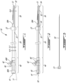
Fig. 1 is a schematic view of a catheter assembly for infusing a pharmacologic agent and for thrombus aspiration in accordance with an embodiment of the present disclosure; -
Fig. 2 is a schematic view of the catheter assembly ofFig. 1 , with a stylet tube therein; -
Fig. 3 is a schematic view of the stylet tube ofFig. 2 ; -
Fig. 4 is a schematic cross-sectional view of a proximal shaft of the catheter assembly ofFig. 1 ; -
Fig. 5 is a sectional cross-sectional view of the proximal shaft of the catheter assembly ofFig. 2 , showing the stylet tube; -
Fig. 6 is cross-sectional view of a delivery tip of a distal shaft of the catheter assembly ofFig. 1 ; -
Fig. 7 is a flowchart of a method for infusing a pharmacologic agent and performing thrombus aspiration in accordance with yet another embodiment of the present disclosure; -
Figs. 8A to 8C illustrate an exemplary sequence of maneuvers at a central hub of the catheter assembly of an embodiment of the present disclosure, to prepare a balloon for being inflated; -
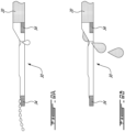
Figs. 9A and 9B illustrate a flush of a stylet and of an aspiration lumen of the catheter assembly of an embodiment of the present disclosure; -
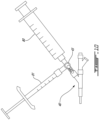
Fig. 10 illustrate an arrangement of syringes at the central hub of the catheter assembly of an embodiment of the present disclosure, to inflate the balloon; and -
Fig. 11 depict the central hub of the catheter assembly of an embodiment of the present disclosure, prior to aspiration. - Referring to
Figs. 1 and 2 , a catheter assembly in accordance with the present disclosure is generally shown at 10. Thecatheter assembly 10 may be used for the infusion of pharmacologic agents and for thrombus aspiration in accordance with the methodology described formethod 70 ofFig. 7 as described hereinafter, through themethod 70 and thecatheter assembly 10 may not be mutually exclusive. In some variants, themethod 70 may be used with a catheter assembly differing thecatheter assembly 10, and thecatheter assembly 10 may be used with a method differing from themethod 70 ofFig. 7 . - The
catheter assembly 10 is introduced over aguide wire 11 that is inserted into any appropriate vessel of the vascular system, such as the coronary artery, with a view to attend to a thrombus. As detailed hereinafter, thecatheter assembly 10 has a hydrophilic surface, so as to slide within the artery with reduced invasiveness. - The
catheter assembly 10 may have one or more of theguide wire 11, though theguide wire 11 may be an add-on that is not part of thecatheter assembly 10, aproximal shaft 20, adistal shaft 30, acatheter hub 40, and/or astylet 50, though thestylet 50 may not be part of thecatheter assembly 10. Other components may be part of thecatheter assembly 10, such as any of those described herein throughFigs. 8A-11 . Theguide wire 11 is the guide upon which parts of thecatheter assembly 10 will be slid or guided in order to reach a target zone. - The
catheter assembly 10 includes theproximal shaft 20, thedistal shaft 30 and/or may include thecatheter hub 40. It may also be said that theguide wire 11 may be part of the catheter. Theproximal shaft 20 is between thedistal shaft 30 and thecatheter hub 40, and serves as a canal for fluid displacement (and possibly solids), among other functions, in a distal direction and/or proximal direction. Theproximal shaft 20 may be the longest component of the catheter (e.g. depending on whether theguide wire 11 is part or not of the catheter). -
Figs. 1 and 2 are schematic views and may not be representative of the length of theproximal shaft 20 relative to thedistal shaft 30 andcatheter hub 40. Thedistal shaft 30 is at the distal end of theproximal shaft 20 and may be one of the output ends of the catheter. Thecatheter hub 40 may be located outside of the body during a procedure, while theproximal shaft 20 is mostly in the body - it may gradually be inserted into the body -, and thedistal shaft 30 is within the body. Thecatheter hub 40 is the interface that may be manipulated by an operator, to perform infusion, inflating and aspiration, for example. Thestylet 50 may be used in the infusion of a pharmacologic agent in the human body, and may also be referred to as a tube. In a variant, thestylet 50 provides some rigidity to thecatheter assembly 10, and may be optionally used to transmit a push force when positioning the catheter device in the vessel. As a possibility, thestylet 50 is a one-time use device. - Referring to
Figs. 1 and 2 , theproximal shaft 20 is shown as having an elongated body, that is merely shown schematically but that may be substantially longer than what is shown inFigs. 1 and 2 . Theproximal shaft 20 may have a monoblock body, for instance that may be extruded. Other constructions include a combination of materials, braiding, etc. Theproximal shaft 20 may include an outer sheath that incorporates therein different tubes that may define different lumens, as described below, or may be monoblock and define one or more of these lumens. Theproximal shaft 20 may also have different constructions, such as by forming an outer jacket supporting different tubes, that will define different types of lumens. The following description pertains to a monoblock body for the shaft portion of theproximal shaft 20, though other types of constructions are considered, and are suggested as well where applicable. - Referring to
Figs. 4 and 5 , theproximal shaft 20 defines anaspiration lumen 21, and aninflating lumen 22. Aninflatable member 23, such as a balloon, is provided at the distal end of theproximal shaft 20 and is in fluid communication with theinflating lumen 22, such that theballoon 23 may be inflated. While theinflatable member 23 may be positioned at or near the distal end of theproximal shaft 20, it may also be located at a junction between theproximal shaft 20 and thedistal shaft 30, and/or may be part of thedistal shaft 30. Theinflatable member 23 may be any suitable type of inflatable material, such as a balloon. According to an embodiment, theinflatable member 23 is made of a substantially compliant membrane, so as to distribute inflating pressure uniformly on the inner surface of the artery or other vessel. - The
aspiration lumen 21 is open-ended at the distal end of theproximal shaft 20. In an embodiment, theaspiration lumen 21 is part of an aspiration tube. Such an aspiration tube may be made from a combination of layers, such as polytetrafluoroethylene, a stainless steel braid (e.g., 0.0005" (0.013 mm) thickness for 0.005" (0.13 mm) width of flat wire with 44 pics/in (17 pics/cm)), and a polyether block amide lumen (e.g., Pebax™. 6333). As an example, theaspiration lumen 21 may have an inner diameter of 0.040" (1.02 mm), though this is merely given as an example. A typical inner diameter of theaspiration lumen 21 ranges from 0.030" (0.76 mm) to 0.045" (1.14 mm), though it may be outside this range. If an aspiration tube is present, it may have a wall thickness of 0.0025" (0.063 mm) and an outer diameter of 0.045" (0.11 mm), again with these values merely provided as examples. Other dimensions are considered as well. According to an embodiment, a polytetrafluoroethylene (PTFE) tube is placed over a mandrel also covered with PTFE, and the stainless steel braid is then positioned on the PTFE. - As observed in
Fig. 5 , theaspiration lumen 21 hosts thestylet 50, such that the pharmacological agent may be infused through theaspiration lumen 21, via thestylet 50, though the infusion lumen of thestylet 50 may be isolated from theaspiration lumen 21. During use, the open distal end of theaspiration lumen 21 is proximally behind the open distal end of thestylet 50, and is hence proximally located in the artery relative to a position of theinflatable member 23. - The inflating
lumen 22 may or may not be part of an inflating tube. The inflatinglumen 22 opens into theinflatable member 23 at the front end of thecatheter assembly 10, for injection of a fluid into theinflatable member 23 via theinflating lumen 22. According to an embodiment, the inflatinglumen 22 is part of a tube that may be made from a single extruded material. However, a combination of layers may be considered as well, such as high-density polyethylene (e.g., HDPE LR734, 25%) and/or polyether block amide (e.g.,Pebax ™ 7233, 75% of outer layer) and/or Plexar™ (e.g., middle layer of Plexar™ 3080). As an example, the inflatinglumen 22 may have an inner diameter of 0.018", though this is merely given as an example. A typical inner diameter of theinflating lumen 22 ranges from 0.001 to 0.038". (0.025 to 0.97 mm) If present, the inflating tube may have a wall thickness of 0.0020" (0.051 mm) and an outer diameter of 0.022" (0.56 mm), again with these values merely provided as examples. Other dimensions are considered as well. Any appropriate type of fluid may be used. For instance, a mixture of saline and iodine contrast is commonly used for inflating balloons in percutaneous coronary intervention. The fluid used to inflate an inflatable member may have suitable contrast to be detected via radiographic imaging. - Referring to
Figs. 1 and 2 and6 , thedistal shaft 30 is shown as having a body tapering from a proximal end toward a distal end, to facilitate its displacement in a vessel. Thedistal shaft 30 may also have a monoblock body, for instance that may be extruded, but this is only an option as thedistal shaft 30 may be constituted of more than one component. For example, thedistal shaft 30 may also have different constructions, such as by forming an outer jacket supporting different tubes, that will define different types of lumens. - The
distal shaft 30 may have anaspiration port 30A. In a variant, theaspiration lumen 21 in theproximal shaft 20 is in fluid communication with the body of thedistal shaft 30 and thus with theaspiration portion 30A, with theaspiration port 30A opening into the vessel. Accordingly, theaspiration port 30A may be a suction port of the catheter. Thedistal shaft 30 may then taper to form a smaller cross-section that may be passed through a thrombus. In a variant, theaspiration lumen 21 in theproximal shaft 20 opens directly into the vessel, such that thedistal shaft 30 is not part of the aspiration step. - The
distal shaft 30 also has aninfusion lumen 31, that is used to deliver the pharmacologic agent at the distal end of the catheter. Theinfusion lumen 31 may be a passage of thestylet 50, or may be in fluid communication with the distal end of thestylet 50 so as to receive the pharmacological agent and deliver same to the infusion target site. As observed, theinfusion lumen 31 may have a funneling geometry in a distal direction. InFig. 6 , this scenario is shown, i.e., thestylet 50 is fluidly connected to theinfusion lumen 31, for the pharmacologic agent to travel through theinfusion lumen 31 and out of the distal tip of thedistal shaft 30. The funnel geometry of theinfusion lumen 31 is optional, but is well suited to ensure that thestylet 50 is in fluid communication with and delivers its pharmacologic agent to theinfusion lumen 31. - The
distal shaft 30 further includes aguide lumen 32 configured to be mounted onto theguide wire 11, for relative movement between theguide wire 11 and thedistal shaft 30. In a variant, theguide lumen 32 opens at the distal end of thedistal shaft 30. In a variant, theguide lumen 32 ends at or near the proximal end of thedistal shaft 30, though it may also extend to part of theproximal shaft 20, at anexit port 33. In a variant, theguide lumen 32 has a length of about 6 inches ± 2 inches (about 15 cm ± 5 cm). Hence, the catheter may only have itsdistal shaft 30 mounted to theguide wire 11, thereby limiting friction, and facilitating displacement. Hence, the catheter may slide along theguide wire 11 during its insertion in the vessel. Thedistal shaft 30, that may also be part of the outer jacket of thecatheter 10, may have an hydrophilic surface, tapering in a distal direction. According to an embodiment, thedistal shaft 30 is made of polyether block amide (e.g., Pebax™ 5533). -
Markers 34 of detectable material may be provided at one or both extremities of thedistal shaft 30 for localization thereof, such as at the distal tip ofinfusion lumen 31. For instance, radio-opaque material may be used for fluoroscopic localization, such as platinum with an iridium content (e.g., 10%). Alternatives are considered as well. According to an embodiment, themarkers 34 have an inner diameter of 0.023" (0.58 mm), a wall of 0.001" (0,025 mm) and an outside diameter of 0.025" (0.63 mm). These values are merely provided as examples. - Referring to
Figs. 1 and 2 , thecatheter hub 40 is shown. Theproximal shaft 20 may emerge out of the human body, such that the open external ends of theaspiration lumen 21 and inflatinglumen 22 are outside of the body, so as to be connected to appropriate means, for example via thecatheter hub 40. Thecatheter hub 40 may have a centraltubular portion 40A with abranch portion 40B diverging from the centraltubular portion 40A. Other configurations are considered such as a single tubular portion with separate ports, a Y-shaped body, etc. In a variant, the centraltubular portion 40A defines aflush port 41 through which suction will be exerted on the catheter, during aspiration. Theflush port 41 may therefore be in fluid communication with theaspiration lumen 21. Thebranch portion 40B may define the inflatingport 42, and may thus be in fluid communication with theinflating lumen 22, so as to direct fluid into theinflatable member 23. Theflush portion 41 may optionally be provided with avalve 43 to control the suction effect. In a variant, thevalve 43 is not part of thecatheter assembly 10. In a variant, thestylet 50 is fitted into the catheter via the centraltubular portion 40A, though other arrangements are connected. -
Collets 44 may be provided to interconnect thehub 40 with theproximal shaft 20, thecollets 44 contributing to maintaining the fluid communication between components, as described above. If present, the tubes associated with thelumens 21 and/or 22, and thestylet 50 may be equipped with suitable connectors (e.g., luers) for connection to the various devices (e.g., syringe). For example, one such connector is shown at 51 at the distal end of thestylet 50. Thestylet 50 may thus be connected to a source of pharmacologic agents, such as a syringe, etc, for the controlled infusion of pharmacologic agents passing through the catheter of thecatheter assembly 10. As mentioned above, the inflatinglumen 22 is connected to a source of fluid for pressurization of theinflatable member 23. - Referring to
Figs. 8A to 8C , another embodiment of thecatheter hub 40 is shown. InFigs. 8A to 8C , thecatheter hub 40 may have a centraltubular portion 40A with abranch portion 40B diverging from the centraltubular portion 40A, and anotherbranch portion 40C also diverging from the centraltubular portion 40A. In a variant, the centraltubular portion 40A defines at its proximal end the injection port, or at the proximal end of part 40A1. Thebranch portion 40B may define the inflatingport 42, and may thus be in fluid communication with theinflating lumen 22, so as to direct fluid into theinflatable member 23. Thebranch portion 40C may be theflush port 41 through which suction will be exerted on the catheter, during aspiration. Theflush port 41 may therefore be in fluid communication with theaspiration lumen 21. Theflush portion 41 may optionally be provided with avalve 43 to control the suction effect, the valve being for example a three-way valve such as a three-way stopcock, as an example among others. In a variant, thevalve 43 is not part of thecatheter assembly 10. In a variant, thestylet 50 is fitted into the catheter via the free end of the centraltubular portion 40A, though other arrangements are connected. -
Collet 44 may be provided to interconnect the part 40A1 of thehub 40 featuring thebranch portion 40B with the part 40A2 of the hub featuring thebranch portion 40C. Thestylet 50 may be accessed when separating part 40A1 from part 40A2, as an example. Other collets may be present, such as to connect the centraltubular portion 40A to theproximal shaft 20, for example. Thecollet 44 contributes to maintaining the fluid communication between components, as described above. If present, the tubes associated with thelumens 21 and/or 22, and thestylet 50 may be equipped with suitable connectors (e.g., luers) for connection to the various devices (e.g., syringe). - The
aspiration lumen 21, such as through theflush portion 41, is connected to an aspiration mechanism, such as a vacuuming syringe or the like. Accordingly, an aspiration action performed at the external end of the catheter causes an aspiration at the open internal end of the aspiration lumen 21 (e.g.,aspiration port 30A), such as at the distal end of theproximal shaft 20 or at an outlet end within thedistal shaft 30. As the open internal end of theaspiration lumen 21 is positioned adjacent to the blood clot in the thrombus aspiration application, the blood clot is vacuumed away from the artery via theaspiration lumen 21. - Any appropriate material may be used for the
shafts stylet 50 is/are, for instance, made of polyimide of medical grade, or any other relatively compliant material. One material that may be used for theshafts 20 and/or 30 and/orstylet 50 is braided reinforced polyimide, to ensure that theaspiration lumen 21 retains its structurally integrity despite the vacuuming pressure, and to maintain the shape during insertion in the vessel, to avoid kinking. During manufacturing, an outer jacket making up the external body of theproximal shaft 20 may be slid over the tubes that would define theaspiration lumen 21 and/or theinflating lumen 22. With tubes fixed and aligned with an outer jacket thereon, the assembly may be passed through a heated die, with the outer jacket fusing all together. Hence, these components are integrally connected to one another, if not monoblock. - Contemplated dimensions are set forth above, by way of example, and for illustrative purposes.
- It is understood that the dimensions may be greater or smaller than those set forth above.
- Now that the
catheter assembly 10 has been described, its non-claimed use in a thrombus aspiration application is described, according to themethod 70 ofFig. 7 . Thenon-claimed method 70 may thus be performed by thecatheter assembly 10, or by other catheter assemblies to infuse pharmacologic agents and perform thrombus aspiration. In a variant, themethod 70 is performed on a cadaver, a model, or on a non-human animal. - According to 71, with the thrombus (a.k.a., blood clot, plaque rupture, artery occlusion) being localized, a distal end of the
guide wire 11 is percutaneously inserted onto a blood vessel (e.g., coronary artery), and is moved up to the thrombus. As an option, theguide wire 11 is moved through the thrombus. A proximal end of theguide wire 11 may be out of the body. - According to 72, the catheter of the
catheter assembly 10 is percutaneously inserted into the vessel proximally of the occlusion, to be directed distally in the vessel toward the thrombus, as being guided onto theguide wire 11. In the case of thecatheter assembly 10, it is thedistal shaft 30 that is mounted onto theguide wire 11 outside of the body, via theguide lumen 32, to then be inserted into the vessel as slid along theguide wire 11. Thestylet 50 may be used to push the catheter into position, thestylet 50 having been assembled prior to step 72 (for example, as assembled), thestylet 50 being in fluid communication with theinfusion lumen 31. It may also be possible to insert thestylet 50 after the combination of thedistal shaft 30 andproximal shaft 20 have being guided to the thrombus by moving onto theguide wire 11. - According to 73, a distal tip of the
distal shaft 30 of the catheter assembly is directed through the blood clot. Theinfusion lumen 31 at the end of thedistal shaft 30 has thus been guided along the guide wire in an over-the-wire or monorail fashion through the occlusion. Therefore, the tip of theinfusion lumen 31 of the catheter is distal of the blood clot after insertion. In a variant, thedistal shaft 30 may be localized by the presence of radio-opaque markers 34. Fluoroscopic imagery or any other appropriate type of imaging may be used to locate the infusion tube relative to the thrombus in the treated vessel. - According to 74, an inflatable member on the catheter assembly is inflated proximally of the blood clot. If the
catheter assembly 10 is used, theinflatable member 23 is inflated via theinflating lumen 22. - According to 75, a pharmacologic agent (e.g., adenosine) is infused into the infarction zone distally of the occlusion. As the vessel is blocked by the occlusion and the
inflated member 23, the pharmacologic agent will diffuse and be absorbed distally to the blood clot. If thecatheter assembly 10 is used, the infusion is performed via thestylet 50, that has been inserted into theproximal shaft 20. It may be required that thestylet 50 be slid into theaspiration lumen 21 and displaced in a distal direction, until the distal tip of thestylet 50 reaches theinfusion lumen 31. In a variant, as mentioned above, thestylet 50 is pre-positioned in fluid communication with theinfusion lumen 31 such that thestylet 50 is moved into position in the vessel concurrently with the positioning of the catheter. This may consequently ensure that thestylet 50 is in suitable fluid communication with theinfusion lumen 31 of thedistal shaft 30, for delivery of the pharmacologic agent. The infusion of the pharmacologic agent may also be performed prior to the inflation of theinflatable member 23. - According to 76, the blood clot is vacuumed out of the artery so as to open the artery. The
aspiration lumen 21 of thecatheter assembly 10 is distally positioned relative to theinflatable member 23, such that theinflatable member 23 may not interfere with the vacuuming. In an embodiment, to increase the efficiency of the vacuuming, thestylet 50 is removed from theaspiration lumen 21, prior to the vacuuming. Thus, theaspiration lumen 21 may serve as aspiration passage and as passage for thestylet 50 for the pharmacologic agent. Stated differently, theaspiration lumen 21 may serve for fluid movement in a distal direction, and in proximal direction. This may be simultaneous and/or sequential. - In one non-claimed embodiment, the aspiration is initiated while the
inflatable member 23 is inflated. This causes a relative negative pressure between the tip of theaspiration lumen 21 orsuction portion 30A and the thrombus. The aspiration may also be initiated after deflation of theinflatable member 23. The deflation may also occur during the aspiration. - Subsequently, the various steps for terminating the intervention are performed, including the removal of the various units of the catheter assembly. For example, the
balloon 23 may be deflated if it hasn't yet been deflated. The catheter may then be slid out of the vessel, as moved along theguide wire 11. Theguide wire 11 may be the last remaining component in the vessel. It is pointed out that themethod 70 may be performed according to any suitable sequence. - With reference to
Figs. 8A-8C , some steps may be done before or during themethod 70. The balloon 23 (Fig. 1 ) may be prepared for use by attaching a three-way stopcock to the inflatingport 42 of thecatheter hub 40. The inflatinglumen 22 and asyringe 80 may have been primed beforehand. Thesyringe 80 may be a larger syringe, i.e., one with a greater volume of solution (e.g., 10 ml). The three-way valve 43 may have its the vertical port in the off position as inFig. 8A . Thesyringe 80 may be attached to thevalve 43, at the proximal port as shown inFig. 8B . To do so, thesyringe 80 may have its plunger partially or fully depressed to the proximal port of the three-way valve 43. Referring toFig. 8C , the plunger of thesyringe 80 may be pulled, and while maintaining the plunger in place, thevalve 43 may be turned counter-clockwise to put the distal port in the OFF position thereby creating a vacuum inside theballoon 23. Thesyringe 80 may be detached after use. - The
stylet 50, installed in the catheter assembly, may be flushed by attaching a syringe containing a liquid such as heparinized saline to the injection port at the free end of the centraltubular portion 40A (if it is located there) of thecatheter hub 40. The plunger of the syringe may be depressed until a jet of fluid exits the distal tip of the catheter and droplets form at the back of the distal tip as inFig. 9A . The catheter may also be flushed by attaching a syringe to theflush port 41 of the catheter and depressing the plunger until fluid exits the aspiration tip as inFig. 9B . The syringe may be detached after use. - The catheter may be used with balloon inflation accessories. The balloon inflation accessories may be set up by connecting the
syringe 80 filled with a liquid, such as at least 5 mL of a 50:50 v/v saline-contrast mixture (as an example among others), to the proximal port of the three-way valve 43 and depressing the plunger of thesyringe 80 to purge air out of the vertical port of the three-way valve 43. Anothersyringe 81, such as one with a lesser volume, may also be filled with a fluid, such as 50:50 v/v saline-contrast mixture (as an example) to the vertical port of the three-way valve 43. - The
distal shaft 30 may be loaded over theguidewire 11 as in 72 of themethod 70. The catheter may be maneuvered under fluoroscopy until the andmarkers 34 are in the treatment area, whereby theforemost marker 34 is positioned distally to the thrombus. Theballoon 23 may be inflated once the catheter is in the treatment area by turning the three-way valve 43 to put the vertical port to the OFF position thereby allowing the vacuum in the catheter to draw fluid from thesyringe 80. After a given amount of time, three-way valve 43 may be actuated to put the proximal port to the OFF position. Under fluoroscopy or like imagining, optionally, thesyringe 81 may incrementally inflate theballoon 23. Once theballoon 23 reaches the required occlusion diameter under fluoroscopy, the three-way valve 43 may be adjusted to put the distal port to the OFF position and maintain the inflation of theballoon 23 as inFig. 10 . - With the
valve 43 in the position ofFig. 10 , the catheter may also be used to deliver a pharmacologic agent by attaching a syringe with a desired infusion volume to the injection port (the free end of the centraltubular portion 40A). The syringe may optionally have a flexible tube. For precaution, the plunger of the syringe may be pulled to withdraw any air bubbles. A continuous pressure may be applied on the plunger of the syringe to deliver the pharmacologic agent via the stylet 50 (Figs. 1 and 2 ). The syringe may be removed after use. - The aspiration catheter assembly may be used with aspiration accessories. The aspiration accessories may be primed by attaching an extension tube to an aspiration syringe containing 5 to 10 mL of heparinized saline, the extension tube having a stopcock that can be placed in an open position to flush the entire length of the extension tube; the stopcock may be closed after flushing and the plunger of the aspiration syringe may be pulled until reaching its full extension before being locked in place.
- After the infusion, the
stylet 50 may be removed. In a variant, this is achieved by removing the part of thecatheter hub 40 including thebranch portion 40C, thereby liberating the aspiration lumen 21 (Figs. 4 and 5 ) - The catheter may be prepared for aspiration by turning the three-
way valve 43 to put the vertical port in the OFF position; the plunger of the syringe may be pulled to deflate theballoon 23, which may be confirmed by fluoroscopy. The three-way valve 43 may then be rotated to put the distal port in the OFF position while maintaining the plunger in the pulled position. The two syringes may be removed after use. Then, as inFig. 11 , the catheter may be used to aspirate by connecting anoptional extension tube 82A of anaspiration syringe 82 attached to theaspiration port 83 of the catheter. If present, avalve 84 on theextension line 82A or elsewhere may be opened. These steps may occur throughout some of the steps of themethod 70 ofFig. 7 . - The non-claimed method can be generally described as being for treating a thrombus (e.g., removing a thrombus) and may include percutaneously positioning a guide wire into an artery toward the thrombus; moving a distal shaft of a catheter along the guide wire until a tip of an infusion lumen of the distal shaft passes through the thrombus to a distal location, while an inflatable member and an aspiration lumen extending into a proximal shaft of the catheter are proximal to the thrombus; and infusing at least one pharmacologic agent distally to the thrombus via the infusion lumen.
- Optionally, the non-claimed method may include inflating the inflatable member proximally to the thrombus the inflating may be performed prior to infusing at least one pharmacologic agent distally to the thrombus; performing an aspiration via the aspiration lumen to aspire the thrombus; positioning the catheter and passing of the tip are done by moving the catheter over a guide wire; moving the distal shaft of the catheter over the guide wire may include only the distal shaft being engaged onto the guide wire by a guide lumen thereof; infusing at least one pharmacologic agent includes infusing the pharmacologic agent in a tube of a stylet extending to the infusion lumen.
- The catheter assembly comprises a distal shaft having a guide lumen and an infusion lumen; a proximal shaft connected to the distal shaft, the proximal shaft defining an aspiration lumen opening at or near the distal shaft, and an inflating lumen; an inflatable member at a distal end of the inflating lumen, the inflatable member configured to inflate upon receiving a fluid from the inflating lumen; a stylet tube extending along the aspiration lumen and in fluid communication with the infusion lumen, the stylet tube configured to supply the infusion lumen with a pharmacologic agent; wherein the catheter assembly is configured to be displaced percutaneously in an artery by the guide lumen moving along a guide wire.
- Optionally, the catheter assembly may include a catheter hub at a proximal end of the proximal shaft. The catheter hub may be in fluid communication with the stylet tube, with the aspiration lumen and with the inflating lumen. The catheter hub may or may not have a port dedicated to the inflating lumen. A three-way valve on the port dedicated to the inflating lumen. Radio-opaque markers may be provided at or near opposed ends of the infusion lumen. The stylet is removable from the aspiration lumen prior to aspiration. Thus the aspiration lumen may be used for infusion (e.g., via the stylet or other tube) and for aspiration. The distal shaft has an aspiration port in fluid communication with the aspiration lumen. A proximal end of the guide lumen may be at the distal shaft.
- The present disclosure also pertains to a non-claimed use of a catheter assembly, in the manner shown in the figures herein, the use of the catheter assembly for removing a thrombus from an artery, the use including: a guide wire for being percutaneously positioned into an artery toward the thrombus; a distal shaft of a catheter for being moved along the guide wire until a tip of an infusion lumen of the distal shaft passes through the thrombus to a distal location; an inflatable member on the catheter and in fluid communication with an inflating lumen of the catheter for inflating and blocking the artery proximally of the thrombus; an aspiration lumen in the catheter extending into a proximal shaft of the catheter to reach a position proximal to the thrombus, for aspiring the thrombus; and a stylet removably in the aspiration lumen of proximal shaft and in fluid communication with the infusion lumen for infusing at least one pharmacologic agent distally to the thrombus via the infusion lumen.
- Numerous pharmacologic agents may be used for the infusion, the doses of which are selected on a case-by-case basis by appropriate personnel. Among the pharmacologic agents that can be used are: adenosine and adenosine receptor agonists, beta blockers, angiotensin-converting enzyme inhibitor, angiotensin-receptor blockers, aldosterone, calcium channel blockers (Verapamil, Diltiazem, Nifedipine), cyclosporin, calpain inhibitor, sodium-proton exchanger inhibitor, NO donor, cox-2 inhibitor, statins, TNF-alpha, endothelin receptor antagonists, antiplatelet, antithrombotic, erythropoietin, anti-leukocyte complement inhibitors, opioid, anesthetic, KATP "openers", insulin, thrombin and fragments, melatonin, H2S, bradykinin, cellular therapy, gene therapy, with the proper catheter.
Claims (10)
- A catheter assembly (10) comprisinga distal shaft (30) having a guide lumen (32);a proximal shaft (20) connected to the distal shaft (30), the proximal shaft (20) defining an aspiration lumen (21) opening at or near the distal shaft (30), and an inflating lumen (22);an inflatable member (23) at a distal end of the inflating lumen (22), the inflatable member (23) configured to inflate upon receiving a fluid from the inflating lumen (22);wherein the catheter assembly (10) is configured to be displaced percutaneously in an artery by the guide lumen (32) moving along a guide wire (11);characterized in thatthe distal shaft (30) has an infusion lumen (31); anda stylet tube (50) extends along the aspiration lumen (21) and is in fluid communication with the infusion lumen (31), the stylet tube (50) configured to supply the infusion lumen (31) with a pharmacologic agent.
- The catheter assembly (10) according to claim 1, further including a catheter hub (40) at a proximal end of the proximal shaft (20).
- The catheter assembly (10) according to claim 2, wherein the catheter hub (40) is in fluid communication with the stylet tube (50), with the aspiration lumen (21) and with the inflating lumen (22).
- The catheter assembly (10) according to claim 3, wherein the catheter hub (40) has a port dedicated to the inflating lumen (22).
- The catheter assembly (10) according to claim 4, including a three-way valve (43) on the port dedicated to the inflating lumen (22).
- The catheter assembly (10) according to any one of claims 1 to 5, including radio-opaque markers (34) at or near opposed ends of the infusion lumen (31).
- The catheter assembly (10) according to any one of claims 1 to 6, wherein the stylet (50) is removable from the aspiration lumen (21) prior to aspiration.
- The catheter assembly (10) according to any one of claims 1 to 7, wherein the distal shaft (30) has an aspiration port (30A) in fluid communication with the aspiration lumen (21).
- The catheter assembly (10) according to any one of claims 1 to 8, wherein a proximal end of the guide lumen (32) is at the distal shaft (30).
- The catheter assembly (10) according to any one of claims 1 to 9, further including a guide wire (11).
Applications Claiming Priority (1)
| Application Number | Priority Date | Filing Date | Title |
|---|---|---|---|
| US202363496978P | 2023-04-19 | 2023-04-19 |
Publications (3)
| Publication Number | Publication Date |
|---|---|
| EP4450110A1 EP4450110A1 (en) | 2024-10-23 |
| EP4450110B1 true EP4450110B1 (en) | 2025-07-02 |
| EP4450110C0 EP4450110C0 (en) | 2025-07-02 |
Family
ID=90810838
Family Applications (1)
| Application Number | Title | Priority Date | Filing Date |
|---|---|---|---|
| EP24171366.8A Active EP4450110B1 (en) | 2023-04-19 | 2024-04-19 | Device for infusion of pharmacologic agents and thrombus aspiration in artery |
Country Status (4)
| Country | Link |
|---|---|
| US (1) | US20240350152A1 (en) |
| EP (1) | EP4450110B1 (en) |
| CA (1) | CA3235709A1 (en) |
| ES (1) | ES3035901T3 (en) |
Families Citing this family (1)
| Publication number | Priority date | Publication date | Assignee | Title |
|---|---|---|---|---|
| US20250186739A1 (en) * | 2023-12-11 | 2025-06-12 | David J. Ternes | Methods and systems for use with a cardiac procedure to reduce post operative atrial fibrillation |
Family Cites Families (3)
| Publication number | Priority date | Publication date | Assignee | Title |
|---|---|---|---|---|
| US6527979B2 (en) * | 1999-08-27 | 2003-03-04 | Corazon Technologies, Inc. | Catheter systems and methods for their use in the treatment of calcified vascular occlusions |
| US9855375B2 (en) * | 2012-07-10 | 2018-01-02 | Valorisation Recherche Hscm, Limited Partnership | Method and device for infusion of pharmacologic agents and thrombus aspiration in artery |
| CN113546281B (en) * | 2020-04-23 | 2025-11-11 | 上海微创医疗器械(集团)有限公司 | Balloon catheter |
-
2024
- 2024-04-18 US US18/639,071 patent/US20240350152A1/en active Pending
- 2024-04-18 CA CA3235709A patent/CA3235709A1/en active Pending
- 2024-04-19 ES ES24171366T patent/ES3035901T3/en active Active
- 2024-04-19 EP EP24171366.8A patent/EP4450110B1/en active Active
Also Published As
| Publication number | Publication date |
|---|---|
| ES3035901T3 (en) | 2025-09-11 |
| EP4450110A1 (en) | 2024-10-23 |
| CA3235709A1 (en) | 2025-10-31 |
| US20240350152A1 (en) | 2024-10-24 |
| EP4450110C0 (en) | 2025-07-02 |
Similar Documents
| Publication | Publication Date | Title |
|---|---|---|
| US6685672B1 (en) | Multi-balloon drug delivery catheter for angiogenesis | |
| US5527292A (en) | Intravascular device for coronary heart treatment | |
| US9463304B2 (en) | Devices, methods and kits for delivery of therapeutic materials to a pancreas | |
| US5919163A (en) | Catheter with slidable balloon | |
| EP1027094B1 (en) | Apparatus for isolated pelvic perfusion | |
| US11207456B2 (en) | Method and device for infusion of pharmacologic agents and thrombus aspiration in artery | |
| EP1681074B1 (en) | Intra-pericardial drug delivery device for angiogenesis | |
| US20010041862A1 (en) | Novel apparatus and method of treating a tumor in the extremity of a patient | |
| US20050261719A1 (en) | Catheter and method of its use | |
| US20160082178A1 (en) | Angiographic methods for identification of feeder vessels | |
| JP2008521536A (en) | Drug delivery device | |
| WO2008006111A2 (en) | Single lumen support catheter for rapid exchange and over the wire use | |
| WO2019027380A1 (en) | Injection method and dilatation device for pressure and ratio desired for liquid and / or medication into vein with balloon catheter | |
| JP2004329552A (en) | Liquid medicine administering catheter | |
| US20180256176A1 (en) | Medical aspiration system and medical thrombectomy system | |
| CN108778390A (en) | Drug coated balloon catheter for arteriovenous shunt | |
| EP4450110A1 (en) | Device for infusion of pharmacologic agents and thrombus aspiration in artery | |
| US20200069921A1 (en) | Device for occlusion isolation and removal | |
| US20240416088A1 (en) | Balloon catheter system | |
| CN120789358A (en) | Guiding suction catheter and catheter system having the same | |
| US20230119571A1 (en) | Guide support for delivering a medical device | |
| WO2020046337A1 (en) | Device for occlusion isolation and removal |
Legal Events
| Date | Code | Title | Description |
|---|---|---|---|
| PUAI | Public reference made under article 153(3) epc to a published international application that has entered the european phase |
Free format text: ORIGINAL CODE: 0009012 |
|
| STAA | Information on the status of an ep patent application or granted ep patent |
Free format text: STATUS: REQUEST FOR EXAMINATION WAS MADE |
|
| 17P | Request for examination filed |
Effective date: 20240419 |
|
| AK | Designated contracting states |
Kind code of ref document: A1 Designated state(s): AL AT BE BG CH CY CZ DE DK EE ES FI FR GB GR HR HU IE IS IT LI LT LU LV MC ME MK MT NL NO PL PT RO RS SE SI SK SM TR |
|
| GRAP | Despatch of communication of intention to grant a patent |
Free format text: ORIGINAL CODE: EPIDOSNIGR1 |
|
| STAA | Information on the status of an ep patent application or granted ep patent |
Free format text: STATUS: GRANT OF PATENT IS INTENDED |
|
| RIC1 | Information provided on ipc code assigned before grant |
Ipc: A61B 90/00 20160101ALN20250114BHEP Ipc: A61M 25/10 20130101ALN20250114BHEP Ipc: A61B 17/22 20060101ALN20250114BHEP Ipc: A61B 17/12 20060101ALI20250114BHEP Ipc: A61M 25/01 20060101ALI20250114BHEP Ipc: A61M 25/00 20060101AFI20250114BHEP |
|
| INTG | Intention to grant announced |
Effective date: 20250123 |
|
| GRAS | Grant fee paid |
Free format text: ORIGINAL CODE: EPIDOSNIGR3 |
|
| GRAA | (expected) grant |
Free format text: ORIGINAL CODE: 0009210 |
|
| STAA | Information on the status of an ep patent application or granted ep patent |
Free format text: STATUS: THE PATENT HAS BEEN GRANTED |
|
| AK | Designated contracting states |
Kind code of ref document: B1 Designated state(s): AL AT BE BG CH CY CZ DE DK EE ES FI FR GB GR HR HU IE IS IT LI LT LU LV MC ME MK MT NL NO PL PT RO RS SE SI SK SM TR |
|
| REG | Reference to a national code |
Ref country code: GB Ref legal event code: FG4D |
|
| REG | Reference to a national code |
Ref country code: CH Ref legal event code: EP |
|
| REG | Reference to a national code |
Ref country code: DE Ref legal event code: R096 Ref document number: 602024000262 Country of ref document: DE |
|
| REG | Reference to a national code |
Ref country code: IE Ref legal event code: FG4D |
|
| U01 | Request for unitary effect filed |
Effective date: 20250702 |
|
| U07 | Unitary effect registered |
Designated state(s): AT BE BG DE DK EE FI FR IT LT LU LV MT NL PT RO SE SI Effective date: 20250715 |
|
| REG | Reference to a national code |
Ref country code: ES Ref legal event code: FG2A Ref document number: 3035901 Country of ref document: ES Kind code of ref document: T3 Effective date: 20250911 |
|
| PG25 | Lapsed in a contracting state [announced via postgrant information from national office to epo] |
Ref country code: IS Free format text: LAPSE BECAUSE OF FAILURE TO SUBMIT A TRANSLATION OF THE DESCRIPTION OR TO PAY THE FEE WITHIN THE PRESCRIBED TIME-LIMIT Effective date: 20251102 |
|
| PG25 | Lapsed in a contracting state [announced via postgrant information from national office to epo] |
Ref country code: NO Free format text: LAPSE BECAUSE OF FAILURE TO SUBMIT A TRANSLATION OF THE DESCRIPTION OR TO PAY THE FEE WITHIN THE PRESCRIBED TIME-LIMIT Effective date: 20251002 |
|
| PG25 | Lapsed in a contracting state [announced via postgrant information from national office to epo] |
Ref country code: HR Free format text: LAPSE BECAUSE OF FAILURE TO SUBMIT A TRANSLATION OF THE DESCRIPTION OR TO PAY THE FEE WITHIN THE PRESCRIBED TIME-LIMIT Effective date: 20250702 |
|
| PG25 | Lapsed in a contracting state [announced via postgrant information from national office to epo] |
Ref country code: GR Free format text: LAPSE BECAUSE OF FAILURE TO SUBMIT A TRANSLATION OF THE DESCRIPTION OR TO PAY THE FEE WITHIN THE PRESCRIBED TIME-LIMIT Effective date: 20251003 |
|
| PG25 | Lapsed in a contracting state [announced via postgrant information from national office to epo] |
Ref country code: CZ Free format text: LAPSE BECAUSE OF FAILURE TO SUBMIT A TRANSLATION OF THE DESCRIPTION OR TO PAY THE FEE WITHIN THE PRESCRIBED TIME-LIMIT Effective date: 20250702 |
|
| PG25 | Lapsed in a contracting state [announced via postgrant information from national office to epo] |
Ref country code: PL Free format text: LAPSE BECAUSE OF FAILURE TO SUBMIT A TRANSLATION OF THE DESCRIPTION OR TO PAY THE FEE WITHIN THE PRESCRIBED TIME-LIMIT Effective date: 20250702 |
|
| PG25 | Lapsed in a contracting state [announced via postgrant information from national office to epo] |
Ref country code: RS Free format text: LAPSE BECAUSE OF FAILURE TO SUBMIT A TRANSLATION OF THE DESCRIPTION OR TO PAY THE FEE WITHIN THE PRESCRIBED TIME-LIMIT Effective date: 20251002 |
|
| PG25 | Lapsed in a contracting state [announced via postgrant information from national office to epo] |
Ref country code: SM Free format text: LAPSE BECAUSE OF FAILURE TO SUBMIT A TRANSLATION OF THE DESCRIPTION OR TO PAY THE FEE WITHIN THE PRESCRIBED TIME-LIMIT Effective date: 20250702 |
|
| PG25 | Lapsed in a contracting state [announced via postgrant information from national office to epo] |
Ref country code: SK Free format text: LAPSE BECAUSE OF FAILURE TO SUBMIT A TRANSLATION OF THE DESCRIPTION OR TO PAY THE FEE WITHIN THE PRESCRIBED TIME-LIMIT Effective date: 20250702 |
|
| U20 | Renewal fee for the european patent with unitary effect paid |
Year of fee payment: 3 Effective date: 20260319 |
|
| PLBE | No opposition filed within time limit |
Free format text: ORIGINAL CODE: 0009261 |
|
| STAA | Information on the status of an ep patent application or granted ep patent |
Free format text: STATUS: NO OPPOSITION FILED WITHIN TIME LIMIT |