EP4450043A2 - Removable power assist for manual wheelchair - Google Patents
Removable power assist for manual wheelchair Download PDFInfo
- Publication number
- EP4450043A2 EP4450043A2 EP24199345.0A EP24199345A EP4450043A2 EP 4450043 A2 EP4450043 A2 EP 4450043A2 EP 24199345 A EP24199345 A EP 24199345A EP 4450043 A2 EP4450043 A2 EP 4450043A2
- Authority
- EP
- European Patent Office
- Prior art keywords
- operably connected
- unit
- wheel
- friction roller
- manual wheelchair
- Prior art date
- Legal status (The legal status is an assumption and is not a legal conclusion. Google has not performed a legal analysis and makes no representation as to the accuracy of the status listed.)
- Pending
Links
- 238000004891 communication Methods 0.000 claims abstract description 34
- 230000007246 mechanism Effects 0.000 claims description 14
- 238000000034 method Methods 0.000 claims description 3
- 238000010586 diagram Methods 0.000 description 5
- 229910001416 lithium ion Inorganic materials 0.000 description 4
- 238000005516 engineering process Methods 0.000 description 3
- 230000006870 function Effects 0.000 description 3
- 239000000463 material Substances 0.000 description 3
- HBBGRARXTFLTSG-UHFFFAOYSA-N Lithium ion Chemical compound [Li+] HBBGRARXTFLTSG-UHFFFAOYSA-N 0.000 description 2
- PXHVJJICTQNCMI-UHFFFAOYSA-N Nickel Chemical compound [Ni] PXHVJJICTQNCMI-UHFFFAOYSA-N 0.000 description 2
- 239000002253 acid Substances 0.000 description 2
- 229910052987 metal hydride Inorganic materials 0.000 description 2
- 238000012986 modification Methods 0.000 description 2
- 230000004048 modification Effects 0.000 description 2
- 208000034819 Mobility Limitation Diseases 0.000 description 1
- 244000137852 Petrea volubilis Species 0.000 description 1
- 229910000831 Steel Inorganic materials 0.000 description 1
- 230000004913 activation Effects 0.000 description 1
- 230000001154 acute effect Effects 0.000 description 1
- 229910052782 aluminium Inorganic materials 0.000 description 1
- XAGFODPZIPBFFR-UHFFFAOYSA-N aluminium Chemical compound [Al] XAGFODPZIPBFFR-UHFFFAOYSA-N 0.000 description 1
- 229910052793 cadmium Inorganic materials 0.000 description 1
- BDOSMKKIYDKNTQ-UHFFFAOYSA-N cadmium atom Chemical compound [Cd] BDOSMKKIYDKNTQ-UHFFFAOYSA-N 0.000 description 1
- OJIJEKBXJYRIBZ-UHFFFAOYSA-N cadmium nickel Chemical compound [Ni].[Cd] OJIJEKBXJYRIBZ-UHFFFAOYSA-N 0.000 description 1
- 230000008878 coupling Effects 0.000 description 1
- 238000010168 coupling process Methods 0.000 description 1
- 238000005859 coupling reaction Methods 0.000 description 1
- 229920001971 elastomer Polymers 0.000 description 1
- 239000006260 foam Substances 0.000 description 1
- 229920001821 foam rubber Polymers 0.000 description 1
- 238000009434 installation Methods 0.000 description 1
- 230000007774 longterm Effects 0.000 description 1
- 229910052759 nickel Inorganic materials 0.000 description 1
- 229920000642 polymer Polymers 0.000 description 1
- 229920001296 polysiloxane Polymers 0.000 description 1
- 229920002635 polyurethane Polymers 0.000 description 1
- 239000004814 polyurethane Substances 0.000 description 1
- 238000009420 retrofitting Methods 0.000 description 1
- 239000004576 sand Substances 0.000 description 1
- 239000010959 steel Substances 0.000 description 1
- 238000004381 surface treatment Methods 0.000 description 1
Images


Classifications
-
- A—HUMAN NECESSITIES
- A61—MEDICAL OR VETERINARY SCIENCE; HYGIENE
- A61G—TRANSPORT, PERSONAL CONVEYANCES, OR ACCOMMODATION SPECIALLY ADAPTED FOR PATIENTS OR DISABLED PERSONS; OPERATING TABLES OR CHAIRS; CHAIRS FOR DENTISTRY; FUNERAL DEVICES
- A61G5/00—Chairs or personal conveyances specially adapted for patients or disabled persons, e.g. wheelchairs
- A61G5/04—Chairs or personal conveyances specially adapted for patients or disabled persons, e.g. wheelchairs motor-driven
- A61G5/047—Chairs or personal conveyances specially adapted for patients or disabled persons, e.g. wheelchairs motor-driven by a modular detachable drive system
-
- A—HUMAN NECESSITIES
- A61—MEDICAL OR VETERINARY SCIENCE; HYGIENE
- A61G—TRANSPORT, PERSONAL CONVEYANCES, OR ACCOMMODATION SPECIALLY ADAPTED FOR PATIENTS OR DISABLED PERSONS; OPERATING TABLES OR CHAIRS; CHAIRS FOR DENTISTRY; FUNERAL DEVICES
- A61G5/00—Chairs or personal conveyances specially adapted for patients or disabled persons, e.g. wheelchairs
- A61G5/02—Chairs or personal conveyances specially adapted for patients or disabled persons, e.g. wheelchairs propelled by the patient or disabled person
-
- A—HUMAN NECESSITIES
- A61—MEDICAL OR VETERINARY SCIENCE; HYGIENE
- A61G—TRANSPORT, PERSONAL CONVEYANCES, OR ACCOMMODATION SPECIALLY ADAPTED FOR PATIENTS OR DISABLED PERSONS; OPERATING TABLES OR CHAIRS; CHAIRS FOR DENTISTRY; FUNERAL DEVICES
- A61G5/00—Chairs or personal conveyances specially adapted for patients or disabled persons, e.g. wheelchairs
- A61G5/02—Chairs or personal conveyances specially adapted for patients or disabled persons, e.g. wheelchairs propelled by the patient or disabled person
- A61G5/021—Chairs or personal conveyances specially adapted for patients or disabled persons, e.g. wheelchairs propelled by the patient or disabled person having particular propulsion mechanisms
- A61G5/022—Chairs or personal conveyances specially adapted for patients or disabled persons, e.g. wheelchairs propelled by the patient or disabled person having particular propulsion mechanisms acting on wheels, e.g. on tires or hand rims
-
- A—HUMAN NECESSITIES
- A61—MEDICAL OR VETERINARY SCIENCE; HYGIENE
- A61G—TRANSPORT, PERSONAL CONVEYANCES, OR ACCOMMODATION SPECIALLY ADAPTED FOR PATIENTS OR DISABLED PERSONS; OPERATING TABLES OR CHAIRS; CHAIRS FOR DENTISTRY; FUNERAL DEVICES
- A61G5/00—Chairs or personal conveyances specially adapted for patients or disabled persons, e.g. wheelchairs
- A61G5/02—Chairs or personal conveyances specially adapted for patients or disabled persons, e.g. wheelchairs propelled by the patient or disabled person
- A61G5/021—Chairs or personal conveyances specially adapted for patients or disabled persons, e.g. wheelchairs propelled by the patient or disabled person having particular propulsion mechanisms
- A61G5/023—Chairs or personal conveyances specially adapted for patients or disabled persons, e.g. wheelchairs propelled by the patient or disabled person having particular propulsion mechanisms acting directly on hubs or axis
-
- A—HUMAN NECESSITIES
- A61—MEDICAL OR VETERINARY SCIENCE; HYGIENE
- A61G—TRANSPORT, PERSONAL CONVEYANCES, OR ACCOMMODATION SPECIALLY ADAPTED FOR PATIENTS OR DISABLED PERSONS; OPERATING TABLES OR CHAIRS; CHAIRS FOR DENTISTRY; FUNERAL DEVICES
- A61G5/00—Chairs or personal conveyances specially adapted for patients or disabled persons, e.g. wheelchairs
- A61G5/08—Chairs or personal conveyances specially adapted for patients or disabled persons, e.g. wheelchairs foldable
-
- A—HUMAN NECESSITIES
- A61—MEDICAL OR VETERINARY SCIENCE; HYGIENE
- A61G—TRANSPORT, PERSONAL CONVEYANCES, OR ACCOMMODATION SPECIALLY ADAPTED FOR PATIENTS OR DISABLED PERSONS; OPERATING TABLES OR CHAIRS; CHAIRS FOR DENTISTRY; FUNERAL DEVICES
- A61G2203/00—General characteristics of devices
- A61G2203/10—General characteristics of devices characterised by specific control means, e.g. for adjustment or steering
- A61G2203/14—Joysticks
-
- A—HUMAN NECESSITIES
- A61—MEDICAL OR VETERINARY SCIENCE; HYGIENE
- A61G—TRANSPORT, PERSONAL CONVEYANCES, OR ACCOMMODATION SPECIALLY ADAPTED FOR PATIENTS OR DISABLED PERSONS; OPERATING TABLES OR CHAIRS; CHAIRS FOR DENTISTRY; FUNERAL DEVICES
- A61G5/00—Chairs or personal conveyances specially adapted for patients or disabled persons, e.g. wheelchairs
- A61G5/04—Chairs or personal conveyances specially adapted for patients or disabled persons, e.g. wheelchairs motor-driven
- A61G5/041—Chairs or personal conveyances specially adapted for patients or disabled persons, e.g. wheelchairs motor-driven having a specific drive-type
- A61G5/046—Chairs or personal conveyances specially adapted for patients or disabled persons, e.g. wheelchairs motor-driven having a specific drive-type at least three driven wheels
-
- B—PERFORMING OPERATIONS; TRANSPORTING
- B60—VEHICLES IN GENERAL
- B60Y—INDEXING SCHEME RELATING TO ASPECTS CROSS-CUTTING VEHICLE TECHNOLOGY
- B60Y2200/00—Type of vehicle
- B60Y2200/80—Other vehicles not covered by groups B60Y2200/10 - B60Y2200/60
- B60Y2200/84—Wheelchairs
Definitions
- the present application generally relates to a removable power assist for a manual wheelchair, and more particularly relates to a device for converting or retrofitting a manual wheelchair into an electric wheelchair.
- What is needed is a device for converting a manual wheelchair into a power driven system in a cost effective, portable, easy to install and use, lightweight, alternately convertible from electric to manual without uninstalling the device.
- the device should be adaptable to existing manual wheelchairs without the need of professional installation.
- a device for converting a manual wheelchair into an electronic wheelchair is provided.
- a manual wheelchair accessory device configured to attach to a manual wheelchair that will convert the manual wheelchair to an electric wheelchair, while still retaining the advantages that manual wheelchairs provide.
- the device includes an attachable power source affixed to a standard manual wheelchair.
- the present invention provides a device having a joystick, a communication unit, one or two motor(s), one or two retractable friction roller(s), an engagement unit and one or two power source(s).
- the joystick is operably connected to a communication unit.
- the communication unit is operably connected to one or two motor(s).
- Each motor includes an axle connected to a rotor.
- a retractable friction roller is mounted on the axle. The roller is placed in contact with a wheel of a manual wheelchair.
- the engagement unit is attached to the manual wheelchair to detachably attach the friction roller to the wheel.
- the power source is operably connected to the motor and the joystick.
- the present invention provides a second motor that is operably connected to the communication unit and the power source.
- the communication unit is operably connected to the joystick.
- the second motor includes a second axle connected to a second rotor.
- This embodiment includes a second friction roller that is mounted on the second axle. The second roller is placed in contact with a second wheel of the manual wheelchair to facilitate powered motion.
- the joystick may be operably connected to the rotors and is operably programmable to generate commands for the motors.
- the present invention easily converts a manual wheelchair to a powered, smart wheelchair.
- Features of the present invention include 1) using the friction roller's contact to the wheel to generate directed force; 2) the ability to engage and disengage the friction roller to the wheels of the wheelchair which allows the user to propel the wheelchair with manual propulsion while the device is disengaged but still attached to the wheelchair - a feature essential if the battery or motor cease to function; 3) the ability to fold the wheelchair with device attached to it without altering the folding of or normal space occupied by a standard manual wheelchair; 4) unit portability.
- the device includes a safety guard to prevent a user's fingers from becoming caught in the motor or the gears.
- the motors are bi-directional and independent of one another so that the motor attached to each wheelchair wheel can turn the opposite direction and rotate the wheelchair in place.
- both acute and long-term care wheelchair companies and individual users can affordably bring their equipment and standard of care to a higher, professional level.
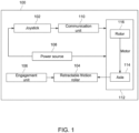
- FIG. 1 illustrates a block diagram of the device 100 in accordance with one embodiment of the present invention.
- the device 100 includes a joystick 102, at least one retractable friction roller 104, along with associated engagement unit 106 and a power source 108.
- the joystick 102 is operably connected to a communication unit 110.
- the joystick 102 is explained in detail in conjunction with FIG. 2 and FIG. 3 of the present invention.
- the communication unit 110 is operably connected to a motor 112.
- the communication unit 110 is explained in detail in conjunction with FIG. 2 of the present invention.
- the motor 112 includes an axle 114 and a rotor 116.
- the motor 112 is explained in detail in conjunction with FIG. 3 of the present invention.
- the axle 114 is shown and explained in detail in conjunction with FIG. 4 of the present invention.
- the retractable friction roller 104 is mounted on the axle 114. During operation of the device 100, the retractable friction roller 104 is put in contact with at least one wheel 206 (show in FIG. 2 ) of a manual wheelchair 202 (shown in FIG. 2 ). The retractable friction roller 104 is explained in detail in conjunction with FIG. 3 and FIG. 4 of the invention.
- the engagement unit 106 is attached to the wheelchair 202 (shown in FIG. 2 ) to detachably attach the retractable friction roller 104 and the wheel (shown in FIG. 2 ).
- the engagement unit 106 is explained in detail in conjunction with FIG. 3 , FIG. 4 and FIG. 5 of the present invention.
- the power source 108 is operably connected to the motor 112 and the joystick 102.
- the power source 108 is shown and explained in detail in conjunction with FIG. 5 of the present invention.
- the device 100 converts the manual wheelchair 202 into an automatic wheelchair.
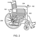
- FIG. 2 illustrates a side view of one embodiment of device 100 attached to a manual wheelchair 202.
- the joystick 102 allows the user to control the direction and speed of the motor 112 (shown in FIG. 2 ).
- the joystick 102 is attached to an arm 204 of the manual wheelchair 202.
- a user is able to control the direction, movement and speed of the device 100 using the joystick 102. More specifically, the movement and speed of the wheel 206 of the wheelchair 202 is controlled by an end-user using the joystick 102 and the communication unit 110 (shown in FIG. 3 ).
- the power source 108 is a battery.
- the batteries may be rechargeable such as but not limited to using an ordinary 110V or 220V charger.
- Sample batteries that may work with this device include but are not limited to a primary battery (non-chargeable) and secondary batteries such as Lithium-ion (Li-ion), Nickel Cadmium (Ni-Cd), Nickel-Metal Hydride (Ni-MH) and Lead-Acid.
- FIG. 3 illustrates a top perspective view of the device 100 attached to the manual wheelchair 202 in accordance with an embodiment of the present invention.
- the retractable friction roller 104 is mounted on the axle 114 (shown in FIG. 1 ) and rotated by activation of the motor 112.
- the device includes a brushless hub motor with a friction surface.
- motors that may be used include but are not limited to a geared hub motor, a brushed hub motor, a brushless geared hub motor, a brushed geared hub motor, a brushed geared hub motor, or any other similar motor.
- Hub motors are very common in power wheelchairs but are typically used for separate wheels that contact the ground directly.
- Friction surfaces may include but are not limited to high friction surface treatments, high friction polymers and high friction detailing applied to the surface that contacts the wheelchair wheel.
- the retractable friction roller 104 is shaped to have a centerless concave rim housing configured to provide high friction surface facing the wheel 206 of the wheelchair 202.
- the centerless concave rim housing acts as a wheel hub to yield a high percentage of surface contact.
- the high friction surface of the retractable friction roller 104 faces the wheelchair wheel 206 and is customizable to fit the curve and or size of the wheel 206.
- the motor 112 is configured to rotate the retractable friction roller 104.
- the retractable friction roller 104 is mounted on the axle 114 (shown in FIG. 1 ) and the rotor 116 (shown in FIG. 1 ) rotates the first axle resulting in rotation of the retractable friction roller 104.
- the motor 112 is a brushless DC motor with a friction surface.
- various types of motor such as geared hub motor, brushed hub motor, brushed geared hub motor etc. may be envisioned without deviating from the scope of the present invention.
- the device 100 further includes a second motor 302 operably connected to the communication unit 110 and the power source 108 (shown in FIG. 1 ).
- the communication unit 110 splits into another communication unit 304 that operably connects to the second motor 302.
- the communication unit 110 and the another communication unit 304 are both operably connected to the joystick 102.
- the joystick 102 further include control buttons 316 operably connected to the motor. The control buttons 316 controls speed of the motor 112 (shown in FIG. 3 ).
- the communication unit 110 and the another communication unit 304 is a single wired (not shown) communication unit operably connected to the joystick 102.
- Examples of the communication unit 110 and the another communication unit 304 include but not limited to cables, wires, Bluetooth, NFC. It would be readily apparent to those skilled in the art that various types of communication unit such as wired or wireless unit may be envisioned without deviating from the scope of the present invention.
- the second motor 302 includes a second axle (not shown) connected to a second rotor (not shown).
- the device 100 further includes a second friction roller 306 mounted on the second axle (not shown).
- the second roller 306 is placed in contact with a second wheel 308 of the manual wheelchair 202.
- the second roller 306 is mounted to the axle 114 and the motor 112 provides motor torque to rotate the second friction roller 306 and the friction roller 104 (not shown).
- the second retractable friction roller 306 includes a centerless concave rim housing configured to provide high friction surface facing the second wheel 308 of the wheelchair 202.
- the principle and function of the second motor 302 and second friction roller 306 is the same as the motor 112 and retractable friction roller 104 as previously described.
- the device 100 further includes a second engagement unit 310 attached to the manual wheelchair 202 to detachably attach the second friction roller 306 and the second wheel 308 of the wheelchair 202.
- the engagement unit 106 detachably attaches the friction roller 104 and the wheel 206.
- the engagement unit 106 and the second engagement unit 310 is attached behind seating area 312 of wheelchair 202 and top of the wheel 206 and the second wheel 308 respectively.
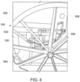
- FIG. 4 illustrates perspective view of engagement unit 106 in accordance with another embodiment of the present invention.
- the engagement unit 106 includes a lever 502 operably connected to a lever mechanism unit 504, a turnbuckle 506 connected to the lever mechanism unit 504 and an attachment unit 508 operably connected to the turnbuckle 506.
- the attachment unit 508 comprises clamps (shown in FIG. 5 ) and a spring loaded unit (shown in FIG. 5 ).
- the retractable friction roller (104, shown in FIG. 3 ) is operably connected to the turnbuckle 506.
- the lever 502 is actuated by the user and results in engaging and disengaging of the retractable friction roller (104, shown in FIG. 3 ) from the wheel 206.
- the lever 502 results in converting a manual wheelchair into a powered wheelchair and vice versa.
- the power source 108 is a battery.
- the batteries are chargeable using an ordinary 110V or 220V charger.
- Examples of battery include but not limited to primary battery (rechargeable) and secondary batteries (non-rechargeable), including but not limited to batteries such as Lithium-ion(Li-ion), Nickel Cadmium(Ni-Cd), Nickel-Metal Hydride(Ni-MH), and Lead-Acid.
- FIG. 5 illustrates perspective view of the device 100 in accordance with another embodiment of the present invention.
- the attachment clamps 402 and a spring loaded unit 404 engage and disengage the retractable friction roller 104 and the wheel 206.
- the friction roller 104 is mounted on the axle 114.
- the friction roller 104 has an opening to receive the axle 114.
- the axle 114 is a cylindrical elongated rod to pass through the opening to rotate the friction roller 104 on receiving motor torque from the rotor (116, shown in FIG. 1 ).
- attachment unit 508 examples include simple mechanical devices such as but not limited to a curved-head bolt, bolt, carriage bolt, T-bolt, T head bolt, round head bolt, barrel bolt, hex-head bolt, spring, screw clamp, mechanical coupling, latch, rod clamp, rail clamp, light, round center mount, mount bracket, pole clamp, pipe clamp, quick release clamp, rack clamp mount, or handlebar clamp mount on the backrest frame of wheelchair 202 and provides contact between the friction roller 104 and the wheelchair wheel 206 respectively.
- simple mechanical devices such as but not limited to a curved-head bolt, bolt, carriage bolt, T-bolt, T head bolt, round head bolt, barrel bolt, hex-head bolt, spring, screw clamp, mechanical coupling, latch, rod clamp, rail clamp, light, round center mount, mount bracket, pole clamp, pipe clamp, quick release clamp, rack clamp mount, or handlebar clamp mount on the backrest frame of wheelchair 202 and provides contact between the friction roller 104 and the wheelchair wheel 206 respectively.
- the total weight for the entire device 100 is approximately 20 pounds. It is expected that the speed is 0-5 MPH adjustable, maximum carrying capacity of around 300 pounds, with a maximum incline of around 10 degrees.
- second retractable friction roller; second engagement unit; and second motor performs exactly same functions as described in the description for retractable friction roller; engagement unit; and motor respectively.
- one of ordinary skill in the art will be able and may make changes to the size and materials of the friction roller; the size and type of motor or battery used; and/or the type of controller or joystick; and the size and type of attachment devices used to fix the device to the manual wheelchair such as but not limited to a screw clamp.
- a casing for each of the two units may be added for safety, convenient travel and appearance.
- the device may be used as a power assist to any object that is traditionally transported on wheels via manual propulsion, such as baggage carts.
- the device may not work if the maximum weight limit is exceeded; the maximum incline is exceeded; the friction roller is not engaged properly to the powertrain; operation on wet surfaces due to slippage, operation on ice, sand, or oily surfaces, if the battery, motor, or grip components are damaged or complete discharged, if the wheels are locked or do not freely rotate, or if operated in excessive heat.
Landscapes
- Health & Medical Sciences (AREA)
- Life Sciences & Earth Sciences (AREA)
- Animal Behavior & Ethology (AREA)
- General Health & Medical Sciences (AREA)
- Public Health (AREA)
- Veterinary Medicine (AREA)
- Handcart (AREA)
- Carriages For Children, Sleds, And Other Hand-Operated Vehicles (AREA)
- Electric Propulsion And Braking For Vehicles (AREA)
- Transmission Devices (AREA)
- Dry Shavers And Clippers (AREA)
Abstract
Description
- This application claims priority to a
U.S. Provisional Application No. 62/663,289 filed on April 27, 2018 - The present application generally relates to a removable power assist for a manual wheelchair, and more particularly relates to a device for converting or retrofitting a manual wheelchair into an electric wheelchair.
- In 2011, an estimated 2.7 million Americans used a wheelchair on a regular basis; up from 1.8 million in 1995. Based off the 2011 Census, 46,000,000 Americans are disabled and receiving income-based assistance. Of that group, 18.2% report ambulatory difficulty. There is also a population that needs a wheelchair temporarily e.g. 2-12 months and would prefer not to incur the expense of an electronic wheelchair even though it is preferred over a manual wheelchair.
- Electronic wheelchairs and many of the innovations in the field are very expensive; and there is a significant price gap between the most expensive manual wheelchair and the cheapest electronic wheelchair, which often ranges in the thousands of dollars. Other limitations of electric wheelchairs, in addition to cost, include: portability (foldable); weight; and structural bulk. There are devices on the market for converting manual wheelchairs to electronic wheelchairs but they are flawed so that they cannot be installed by an end user sitting in the chair, are heavy, not portable, have poor surface contact for the propulsion system and/or cannot be disengaged without uninstalling the device from the chair.
- What is needed is a device for converting a manual wheelchair into a power driven system in a cost effective, portable, easy to install and use, lightweight, alternately convertible from electric to manual without uninstalling the device. The device should be adaptable to existing manual wheelchairs without the need of professional installation.
- In accordance with teachings of the present invention a device for converting a manual wheelchair into an electronic wheelchair is provided. Herein described is a manual wheelchair accessory device configured to attach to a manual wheelchair that will convert the manual wheelchair to an electric wheelchair, while still retaining the advantages that manual wheelchairs provide. The device includes an attachable power source affixed to a standard manual wheelchair.
- In one embodiment, the present invention provides a device having a joystick, a communication unit, one or two motor(s), one or two retractable friction roller(s), an engagement unit and one or two power source(s). The joystick is operably connected to a communication unit. The communication unit is operably connected to one or two motor(s). Each motor includes an axle connected to a rotor. A retractable friction roller is mounted on the axle. The roller is placed in contact with a wheel of a manual wheelchair. The engagement unit is attached to the manual wheelchair to detachably attach the friction roller to the wheel. The power source is operably connected to the motor and the joystick.
- In one embodiment, the present invention provides a second motor that is operably connected to the communication unit and the power source. The communication unit is operably connected to the joystick. The second motor includes a second axle connected to a second rotor. This embodiment includes a second friction roller that is mounted on the second axle. The second roller is placed in contact with a second wheel of the manual wheelchair to facilitate powered motion. In another embodiment, the joystick may be operably connected to the rotors and is operably programmable to generate commands for the motors.
- The present invention easily converts a manual wheelchair to a powered, smart wheelchair. Features of the present invention include 1) using the friction roller's contact to the wheel to generate directed force; 2) the ability to engage and disengage the friction roller to the wheels of the wheelchair which allows the user to propel the wheelchair with manual propulsion while the device is disengaged but still attached to the wheelchair - a feature essential if the battery or motor cease to function; 3) the ability to fold the wheelchair with device attached to it without altering the folding of or normal space occupied by a standard manual wheelchair; 4) unit portability. In one embodiment, the device includes a safety guard to prevent a user's fingers from becoming caught in the motor or the gears. In another embodiment, the motors are bi-directional and independent of one another so that the motor attached to each wheelchair wheel can turn the opposite direction and rotate the wheelchair in place. Using the present invention, both acute and long-term care wheelchair companies and individual users can affordably bring their equipment and standard of care to a higher, professional level.
-
-
FIG. 1 illustrates a block diagram of a device in accordance with an embodiment of the present invention. -
FIG. 2 illustrates a side view of a device attached to a manual wheelchair in accordance with an embodiment of the present invention. -
FIG. 3 illustrates a top perspective view of the device attached to the manual wheelchair in accordance with an embodiment of the present invention. -
FIG. 4 illustrates a perspective view of an engagement unit in accordance with another embodiment of the present invention. -
FIG. 5 illustrates a perspective view of the device in accordance with another embodiment of the present invention. - While various embodiments of the present disclosure are disclosed, it should be understood that they are presented as examples only, and are not intended to be limiting. Similarly, the drawings and diagrams depict structural or architectural examples or alternate configurations of the invention, which are provided to aid in understanding the features and functionality of the various embodiments of the invention but are not intended to be limiting. The embodiments and features may be implemented and/or altered in a variety of ways known to those of ordinary skill the art.
-
FIG. 1 illustrates a block diagram of thedevice 100 in accordance with one embodiment of the present invention. In this embodiment, thedevice 100 includes ajoystick 102, at least oneretractable friction roller 104, along with associatedengagement unit 106 and apower source 108. Thejoystick 102 is operably connected to acommunication unit 110. Thejoystick 102 is explained in detail in conjunction withFIG. 2 andFIG. 3 of the present invention. - The
communication unit 110 is operably connected to amotor 112. Thecommunication unit 110 is explained in detail in conjunction withFIG. 2 of the present invention. Themotor 112 includes anaxle 114 and arotor 116. Themotor 112 is explained in detail in conjunction withFIG. 3 of the present invention. Theaxle 114 is shown and explained in detail in conjunction withFIG. 4 of the present invention. - The
retractable friction roller 104 is mounted on theaxle 114. During operation of thedevice 100, theretractable friction roller 104 is put in contact with at least one wheel 206 (show inFIG. 2 ) of a manual wheelchair 202 (shown inFIG. 2 ). Theretractable friction roller 104 is explained in detail in conjunction withFIG. 3 andFIG. 4 of the invention. - The
engagement unit 106 is attached to the wheelchair 202 (shown inFIG. 2 ) to detachably attach theretractable friction roller 104 and the wheel (shown inFIG. 2 ). Theengagement unit 106 is explained in detail in conjunction withFIG. 3 ,FIG. 4 andFIG. 5 of the present invention. Thepower source 108 is operably connected to themotor 112 and thejoystick 102. Thepower source 108 is shown and explained in detail in conjunction withFIG. 5 of the present invention. Thedevice 100 converts themanual wheelchair 202 into an automatic wheelchair. -
FIG. 2 illustrates a side view of one embodiment ofdevice 100 attached to amanual wheelchair 202. Thejoystick 102 allows the user to control the direction and speed of the motor 112 (shown inFIG. 2 ). In an embodiment, thejoystick 102 is attached to anarm 204 of themanual wheelchair 202. - In one embodiment, a user is able to control the direction, movement and speed of the
device 100 using thejoystick 102. More specifically, the movement and speed of thewheel 206 of thewheelchair 202 is controlled by an end-user using thejoystick 102 and the communication unit 110 (shown inFIG. 3 ). - In one embodiment, the
joystick 102 is programmable and enabled to store instructions for controlling the speed and direction of motor 112 (shown inFIG. 1 ). Thejoystick 102 receives power from the power source 108 (shown inFIG. 1 ). The use of a battery operated joystick is known for controlling power wheelchairs. - In one embodiment, the
power source 108 is a battery. The batteries may be rechargeable such as but not limited to using an ordinary 110V or 220V charger. Sample batteries that may work with this device include but are not limited to a primary battery (non-chargeable) and secondary batteries such as Lithium-ion (Li-ion), Nickel Cadmium (Ni-Cd), Nickel-Metal Hydride (Ni-MH) and Lead-Acid. -
FIG. 3 illustrates a top perspective view of thedevice 100 attached to themanual wheelchair 202 in accordance with an embodiment of the present invention. In this configuration, theretractable friction roller 104 is mounted on the axle 114 (shown inFIG. 1 ) and rotated by activation of themotor 112. - In one embodiment, the device includes a brushless hub motor with a friction surface. Types of motors that may be used include but are not limited to a geared hub motor, a brushed hub motor, a brushless geared hub motor, a brushed geared hub motor, a brushed geared hub motor, or any other similar motor. Hub motors are very common in power wheelchairs but are typically used for separate wheels that contact the ground directly. Friction surfaces may include but are not limited to high friction surface treatments, high friction polymers and high friction detailing applied to the surface that contacts the wheelchair wheel.
- In the present invention, the
retractable friction roller 104 is placed in contact with at least onewheel 206 of themanual wheelchair 202 to rotate thewheel 206 and move thewheelchair 202. Theretractable friction roller 104 rotates thewheel 206 by friction force. This is a unique feature of the present invention. Other devices are commonly based on motor to ground movements, PAW uses a friction roller to the wheel to generate movement. - In one embodiment, the
retractable friction roller 104 is shaped to have a centerless concave rim housing configured to provide high friction surface facing thewheel 206 of thewheelchair 202. The centerless concave rim housing acts as a wheel hub to yield a high percentage of surface contact. In one embodiment, the high friction surface of theretractable friction roller 104 faces thewheelchair wheel 206 and is customizable to fit the curve and or size of thewheel 206. - In an embodiment, the material of high friction surface of the
retractable friction roller 104 is rubber or polyurethane. However, it would be readily apparent to those skilled in the art that various types of material such as silicone, foam, sand paper, grit tape, sponge-rubber foam etc. may be envisioned without deviating from the scope of the present invention. In another embodiment, thewheels 206 ofwheelchair 202 are made using a high friction surface, and theroller 104 is made of steel, aluminum or other similar hardened, textured surface. - The
motor 112 is configured to rotate theretractable friction roller 104. Theretractable friction roller 104 is mounted on the axle 114 (shown inFIG. 1 ) and the rotor 116 (shown inFIG. 1 ) rotates the first axle resulting in rotation of theretractable friction roller 104. In an embodiment, themotor 112 is a brushless DC motor with a friction surface. However, it would be readily apparent to those skilled in the art that various types of motor such as geared hub motor, brushed hub motor, brushed geared hub motor etc. may be envisioned without deviating from the scope of the present invention. - In another embodiment, the
device 100 further includes asecond motor 302 operably connected to thecommunication unit 110 and the power source 108 (shown inFIG. 1 ). Thecommunication unit 110 splits into anothercommunication unit 304 that operably connects to thesecond motor 302. Thecommunication unit 110 and the anothercommunication unit 304 are both operably connected to thejoystick 102. In another embodiment, thejoystick 102 further includecontrol buttons 316 operably connected to the motor. Thecontrol buttons 316 controls speed of the motor 112 (shown inFIG. 3 ). - In an embodiment, the
communication unit 110 and the anothercommunication unit 304 is a single wired (not shown) communication unit operably connected to thejoystick 102. Examples of thecommunication unit 110 and the anothercommunication unit 304 include but not limited to cables, wires, Bluetooth, NFC. It would be readily apparent to those skilled in the art that various types of communication unit such as wired or wireless unit may be envisioned without deviating from the scope of the present invention. - The
second motor 302 includes a second axle (not shown) connected to a second rotor (not shown). In this embodiment, thedevice 100 further includes asecond friction roller 306 mounted on the second axle (not shown). Thesecond roller 306 is placed in contact with asecond wheel 308 of themanual wheelchair 202. Alternatively, thesecond roller 306 is mounted to theaxle 114 and themotor 112 provides motor torque to rotate thesecond friction roller 306 and the friction roller 104 (not shown). - Similarly, to the
retractable friction roller 104, the secondretractable friction roller 306 includes a centerless concave rim housing configured to provide high friction surface facing thesecond wheel 308 of thewheelchair 202. The principle and function of thesecond motor 302 andsecond friction roller 306 is the same as themotor 112 andretractable friction roller 104 as previously described. - In another embodiment of the present invention, the
device 100 further includes asecond engagement unit 310 attached to themanual wheelchair 202 to detachably attach thesecond friction roller 306 and thesecond wheel 308 of thewheelchair 202. Theengagement unit 106 detachably attaches thefriction roller 104 and thewheel 206. Theengagement unit 106 and thesecond engagement unit 310 is attached behindseating area 312 ofwheelchair 202 and top of thewheel 206 and thesecond wheel 308 respectively. -
FIG. 4 illustrates perspective view ofengagement unit 106 in accordance with another embodiment of the present invention. Theengagement unit 106 includes alever 502 operably connected to alever mechanism unit 504, a turnbuckle 506 connected to thelever mechanism unit 504 and anattachment unit 508 operably connected to theturnbuckle 506. Theattachment unit 508 comprises clamps (shown inFIG. 5 ) and a spring loaded unit (shown inFIG. 5 ). - In one embodiment of the device, the retractable friction roller (104, shown in
FIG. 3 ) is operably connected to theturnbuckle 506. Thelever 502 is actuated by the user and results in engaging and disengaging of the retractable friction roller (104, shown inFIG. 3 ) from thewheel 206. Thus thelever 502 results in converting a manual wheelchair into a powered wheelchair and vice versa. - With reference to
FIG. 1 , in an embodiment of the present invention, thepower source 108 is a battery. The batteries are chargeable using an ordinary 110V or 220V charger. Examples of battery include but not limited to primary battery (rechargeable) and secondary batteries (non-rechargeable), including but not limited to batteries such as Lithium-ion(Li-ion), Nickel Cadmium(Ni-Cd), Nickel-Metal Hydride(Ni-MH), and Lead-Acid. -
FIG. 5 illustrates perspective view of thedevice 100 in accordance with another embodiment of the present invention. The attachment clamps 402 and a spring loadedunit 404 engage and disengage theretractable friction roller 104 and thewheel 206. - With reference to
FIG. 1 , thefriction roller 104 is mounted on theaxle 114. In an embodiment of the present invention, thefriction roller 104 has an opening to receive theaxle 114. Theaxle 114 is a cylindrical elongated rod to pass through the opening to rotate thefriction roller 104 on receiving motor torque from the rotor (116, shown inFIG. 1 ). - Examples of the
attachment unit 508 include simple mechanical devices such as but not limited to a curved-head bolt, bolt, carriage bolt, T-bolt, T head bolt, round head bolt, barrel bolt, hex-head bolt, spring, screw clamp, mechanical coupling, latch, rod clamp, rail clamp, light, round center mount, mount bracket, pole clamp, pipe clamp, quick release clamp, rack clamp mount, or handlebar clamp mount on the backrest frame ofwheelchair 202 and provides contact between thefriction roller 104 and thewheelchair wheel 206 respectively. - The total weight for the
entire device 100 is approximately 20 pounds. It is expected that the speed is 0-5 MPH adjustable, maximum carrying capacity of around 300 pounds, with a maximum incline of around 10 degrees. - It would be readily apparent to those skilled in the art that second retractable friction roller; second engagement unit; and second motor performs exactly same functions as described in the description for retractable friction roller; engagement unit; and motor respectively.
- In other embodiments one of ordinary skill in the art will be able and may make changes to the size and materials of the friction roller; the size and type of motor or battery used; and/or the type of controller or joystick; and the size and type of attachment devices used to fix the device to the manual wheelchair such as but not limited to a screw clamp. In one embodiment a casing for each of the two units may be added for safety, convenient travel and appearance. In another embodiment, the device may be used as a power assist to any object that is traditionally transported on wheels via manual propulsion, such as baggage carts.
- Potential limitations include the following: the device may not work if the maximum weight limit is exceeded; the maximum incline is exceeded; the friction roller is not engaged properly to the powertrain; operation on wet surfaces due to slippage, operation on ice, sand, or oily surfaces, if the battery, motor, or grip components are damaged or complete discharged, if the wheels are locked or do not freely rotate, or if operated in excessive heat.
- In the foregoing description, it will be readily appreciated by those skilled in the art that modifications may be made to the invention without departing from the concepts disclosed herein. Such modifications are to be considered as included in the following claims, unless the claims by their language expressly state otherwise.
- Terms and phrases used in this document, and variations thereof, unless otherwise expressly stated, should be construed as open ended as opposed to limiting. As examples of the foregoing: the term "including" should be read as meaning "including, without limitation" or the like; the term "example" is used to provide exemplary instances of the item in discussion, not an exhaustive or limiting list thereof; the terms "a" or "an" should be read as meaning "at least one," "one or more" or the like; and adjectives such as "conventional," "traditional," "normal," "standard," "known" and terms of similar meaning should not be construed as limiting the item described to a given time period or to an item available as of a given time, but instead should be read to encompass conventional, traditional, normal, or standard technologies that may be available or known now or at any time in the future.
- Likewise, where this document refers to technologies that would be apparent or known to one of ordinary skill in the art, such technologies encompass those apparent or known to the skilled artisan now or at any time in the future. Furthermore, the use of plurals can also refer to the singular, including without limitation when a term refers to one or more of a particular item; likewise, the use of a singular term can also include the plural, unless the context dictates otherwise.
- The presence of broadening words and phrases such as "one or more," "at least," "but not limited to" or other like phrases in some instances shall not be read to mean that the narrower case is intended or required in instances where such broadening phrases may be absent. Additionally, the various embodiments set forth herein are described in terms of exemplary block diagrams, flow charts and other illustrations. As will become apparent to one of ordinary skill in the art after reading this document, the illustrated embodiments and their various alternatives can be implemented without confinement to the illustrated examples. For example, block diagrams and their accompanying description should not be construed as mandating a particular architecture or configuration.
- Although the disclosure is described above in terms of various exemplary embodiments and implementations, it should be understood that the various features, aspects and functionality described in one or more of the individual embodiments are not limited in their applicability to the particular embodiment with which they are described, but instead can be applied, alone or in various combinations, to one or more of the other embodiments of the disclosure, whether or not such embodiments are described and whether or not such features are presented as being a part of a described embodiment. Thus, the breadth and scope of the present invention should not be limited by any of the above-described exemplary embodiments.
- The following are preferred aspects according to the present disclosure.
- CLAUSE 1. A device comprising:
- a joystick operably connected to a communication unit, the communication unit operably connected to a motor; said motor comprising an axle connected to a rotor;
- a retractable friction roller mounted on the axle and said roller placed in contact with a wheel of a manual wheelchair;
- an engagement unit attached to the wheelchair to detachably attach the retractable friction roller and the wheel; and
- a power source operably connected to the motor and the joystick.
- CLAUSE 2. The friction roller according to clause 1 comprising a centerless concave rim housing configured to provide high friction surface facing the wheel of the wheelchair.
- CLAUSE 3. The device according to clause 1 further comprising a second motor operably connected to the communication unit and the power source.
- CLAUSE 4. The second motor according to clause 3 comprising a second axle connected to a second rotor.
- CLAUSE 5. The device according to clause 4 further comprising a second retractable friction roller mounted on the second axle, and said second roller placed in contact with a second wheel of the manual wheelchair.
- CLAUSE 6. The device according to clause 5 further comprising a second engagement unit attached to the manual wheelchair to detachably attach the second friction roller and the second wheel of the wheelchair.
- CLAUSE 7. The second retractable friction roller according to clause 5 comprising a second centerless concave rim housing configured to provide high friction surface facing the second wheel of the manual wheelchair.
- CLAUSE 8. The joystick according to clause 3 operably programmable to generate commands for the motor and the second motor.
- CLAUSE 9. The friction roller according to clause 1 contacts the wheel behind a seating area of the wheelchair.
- CLAUSE 10. The second friction roller according to clause 5 contacts the second wheel behind the seating area.
- CLAUSE 11. The engagement unit according to clause 1 further comprises:
a lever operably connected to a lever mechanism unit; said lever mechanism unit operably connected to a turnbuckle; and said turnbuckle operably connected to an attachment unit. - CLAUSE 12. The second engagement unit according to clause 6 further comprises:
a second lever operably connected to a second lever mechanism unit; said second lever mechanism unit operably connected to a second turnbuckle; and said second turnbuckle operably connected to a second attachment unit. - CLAUSE 13. The attachment unit according to clause 12 comprises: a spring loaded unit operably connected to the retractable friction roller; and a clamp operably connected to the spring loaded unit.
- CLAUSE 14. The second attachment unit according to clause 13 comprises: a second operably connected to the second retractable friction roller; and a second clamp operably connected to the spring loaded unit.
- CLAUSE 15. A method for converting a manual wheelchair to electronic wheelchair comprising a step of using a device comprising:
a joystick operably connected to a communication unit, said communication unit operably connected to a motor; said motor comprising an axle connected to a rotor; - a retractable friction roller mounted on the axle, and said roller placed in contact with a wheel of a manual wheelchair;
- an engagement unit attached to the wheelchair to detachably attach the friction roller and the wheel; and
- a power source operably connected to the motor and the joystick.
Claims (6)
- A device (100) for converting a foldable manual wheelchair (202) to a foldable electronic wheelchair (202), comprising:a joystick (102) operably connected to a communication unit (110), the communication unit (110) operably connected to a first motor (112), the first motor (112) comprising a first axle (114) connected to a first rotor (116);a first retractable friction roller (104) mounted on the first axle (114);a first engagement unit (106) which is attachable to the foldable manual wheelchair (202) behind a seating area and top of a first wheel (206) of the foldable manual wheelchair (202) to detachably attach the first retractable friction roller (104) to the first wheel (206) behind the seating area of the foldable manual wheelchair (202) to generate directed force by contact between the first retractable friction roller (104) and the first wheel (206);a power source (108) operably connected to the first motor (112) and the joystick (102);a second motor (302) operably connected to the communication unit (110) and the power source (108), the second motor (302) comprising a second axle connected to a second rotor;a second retractable friction roller (306) mounted on the second axle; anda second engagement unit (310) which is attachable to the foldable manual wheelchair (202) behind the seating area and top of a second wheel (308) of the foldable manual wheelchair (202) to detachably attach the second retractable friction roller (306) to the second wheel (308) behind the seating area of the foldable manual wheelchair (202) to generate directed force by contact between the second retractable friction roller (306) and the second wheel (308),wherein the first engagement unit (106) comprises:
a first lever (502) operably connected to a first lever mechanism unit (504), the first lever mechanism unit (504) being operably connected to a first turnbuckle (506), the first turnbuckle (506) being operably connected to a first attachment unit (508);and wherein the second engagement unit (310) further comprises:
a second lever operably connected to a second lever mechanism unit, the second lever mechanism unit being operably connected to a second turnbuckle, the second turnbuckle being operably connected to a second attachment unit;and wherein the first attachment unit (508) comprises:a first spring loaded unit (404) operably connected to the first retractable friction roller (104); anda first clamp (402) operably connected to the first spring loaded unit (404);and wherein the second attachment unit comprises:a second spring loaded unit operably connected to the second retractable friction roller (306); anda second clamp operably connected to the second spring loaded unit. - A device (100) according to claim 1, wherein the joystick (102) is operably programmable to generate commands for the first motor (112) and the second motor (302), optionally wirelessly.
- A device (100) according to claim 1 or 2, wherein:the first retractable friction roller (104) comprises a centerless concave rim housing configured to face the first wheel (206) of the manual wheelchair (202) to provide a high friction surface contact with the first wheel (206); andthe second retractable friction roller (306) comprises a centerless concave rim housing configured to face the second wheel (308) of the manual wheelchair (202) to provide a high friction surface contact with the second wheel.
- A device (100) according to any preceding claim, wherein the total weight for the entire device (100) is approximately 9 kilograms (20 pounds).
- A foldable wheelchair (202) comprising a device (100) according to any of claims 1 to 4.
- A method of attaching a device (100) to a foldable manual wheelchair (202) to convert the foldable manual wheelchair to a foldable electronic wheelchair (202), the device comprising:a joystick (102) operably connected to a communication unit (110), the communication unit (110) operably connected to a first motor (112), the first motor (112) comprising a first axle (114) connected to a first rotor (116);a first retractable friction roller (104) mounted on the first axle (114);a first engagement unit (106) which is attachable to the foldable manual wheelchair (202) behind a seating area and top of a first wheel (206) of the foldable manual wheelchair (202) to detachably attach the first retractable friction roller (104) to the first wheel (206) behind the seating area of the foldable manual wheelchair (202) to generate directed force by contact between the first retractable friction roller (104) and the first wheel (206);a power source (108) operably connected to the first motor (112) and the joystick (102);a second motor (302) operably connected to the communication unit (110) and the power source (108), the second motor (302) comprising a second axle connected to a second rotor;a second retractable friction roller (306) mounted on the second axle; anda second engagement unit (310) which is attachable to the foldable manual wheelchair (202) behind the seating area and top of a second wheel (308) of the foldable manual wheelchair (202) to detachably attach the second retractable friction roller (306) to the second wheel (308) behind the seating area of the foldable manual wheelchair (202) to generate directed force by contact between the second retractable friction roller (306) and the second wheel (308),wherein the first engagement unit (106) comprises:
a first lever (502) operably connected to a first lever mechanism unit (504), the first lever mechanism unit (504) being operably connected to a first turnbuckle (506), the first turnbuckle (506) being operably connected to a first attachment unit (508);and wherein the second engagement unit (310) further comprises:
a second lever operably connected to a second lever mechanism unit, the second lever mechanism unit being operably connected to a second turnbuckle, the second turnbuckle being operably connected to a second attachment unit;and wherein the first attachment unit (508) comprises:a first spring loaded unit (404) operably connected to the first retractable friction roller (104); anda first clamp (402) operably connected to the first spring loaded unit (404);and wherein the second attachment unit comprises:a second spring loaded unit operably connected to the second retractable friction roller (306); anda second clamp operably connected to the second spring loaded unit,the method comprising:attaching the first clamp (402) to the foldable manual wheelchair (202) to attach the first engagement unit (106) to the foldable manual wheelchair (202) behind the seating area and top of the first wheel of the foldable manual wheelchair (202); andattaching the second clamp to the foldable manual wheelchair (202) to attach the second engagement unit (310) to the foldable manual wheelchair (202) behind the seating area and top of the second wheel of the foldable manual wheelchair (202).
Applications Claiming Priority (3)
| Application Number | Priority Date | Filing Date | Title |
|---|---|---|---|
| US201862663289P | 2018-04-27 | 2018-04-27 | |
| EP19850104.1A EP3784193B1 (en) | 2018-04-27 | 2019-04-26 | Removable power assist for manual wheelchair |
| PCT/US2019/029266 WO2020036659A2 (en) | 2018-04-27 | 2019-04-26 | Removable power assist for manual wheelchair |
Related Parent Applications (2)
| Application Number | Title | Priority Date | Filing Date |
|---|---|---|---|
| EP19850104.1A Division EP3784193B1 (en) | 2018-04-27 | 2019-04-26 | Removable power assist for manual wheelchair |
| EP19850104.1A Division-Into EP3784193B1 (en) | 2018-04-27 | 2019-04-26 | Removable power assist for manual wheelchair |
Publications (2)
| Publication Number | Publication Date |
|---|---|
| EP4450043A2 true EP4450043A2 (en) | 2024-10-23 |
| EP4450043A3 EP4450043A3 (en) | 2025-01-29 |
Family
ID=68290852
Family Applications (2)
| Application Number | Title | Priority Date | Filing Date |
|---|---|---|---|
| EP19850104.1A Active EP3784193B1 (en) | 2018-04-27 | 2019-04-26 | Removable power assist for manual wheelchair |
| EP24199345.0A Pending EP4450043A3 (en) | 2018-04-27 | 2019-04-26 | Removable power assist for manual wheelchair |
Family Applications Before (1)
| Application Number | Title | Priority Date | Filing Date |
|---|---|---|---|
| EP19850104.1A Active EP3784193B1 (en) | 2018-04-27 | 2019-04-26 | Removable power assist for manual wheelchair |
Country Status (26)
| Country | Link |
|---|---|
| US (1) | US10517780B2 (en) |
| EP (2) | EP3784193B1 (en) |
| JP (1) | JP2021514799A (en) |
| CN (1) | CN112423717A (en) |
| AU (2) | AU2019322492B2 (en) |
| BR (1) | BR112020021039B1 (en) |
| CA (1) | CA3097880C (en) |
| CL (1) | CL2020002666A1 (en) |
| CO (1) | CO2020013529A2 (en) |
| CR (1) | CR20200559A (en) |
| CU (1) | CU24656B1 (en) |
| DE (1) | DE112019000072B4 (en) |
| EC (1) | ECSP20064588A (en) |
| ES (1) | ES2996957T3 (en) |
| HU (1) | HUE068964T2 (en) |
| IL (1) | IL277834B (en) |
| JO (1) | JOP20200255A1 (en) |
| MX (1) | MX387938B (en) |
| MY (1) | MY200598A (en) |
| NZ (1) | NZ768436A (en) |
| PE (1) | PE20210146A1 (en) |
| RU (1) | RU2754373C1 (en) |
| SA (1) | SA520420341B1 (en) |
| SG (1) | SG11202009712RA (en) |
| WO (1) | WO2020036659A2 (en) |
| ZA (1) | ZA202005900B (en) |
Families Citing this family (10)
| Publication number | Priority date | Publication date | Assignee | Title |
|---|---|---|---|---|
| US11523951B2 (en) | 2018-04-27 | 2022-12-13 | Roda Futura, Llc | Portable power assist for manual wheelchairs |
| US10945899B2 (en) * | 2018-04-27 | 2021-03-16 | Roda Fuutra, Llc | Removable power assist for manual wheelchair |
| US11660241B2 (en) | 2018-04-27 | 2023-05-30 | Roda Futura, Llc | Exchangeable universal wheelchair power assist |
| US11529274B2 (en) * | 2018-04-27 | 2022-12-20 | Roda Futura, Llc | Removable power assist for manual wheelchair |
| US11154443B2 (en) | 2018-04-27 | 2021-10-26 | Roda Futura, Llc | Removable power assist for manual wheelchair |
| US11389351B2 (en) * | 2018-06-27 | 2022-07-19 | Motion Composites Inc. | Wheelchair footrest assembly |
| WO2020206374A1 (en) | 2019-04-05 | 2020-10-08 | Udeego, Inc. | Electrical power assistance device for transport wheelchair |
| ES2902511A1 (en) * | 2020-09-28 | 2022-03-28 | Garcia Juan Antonio Carrasco | Removable mechanical traction device (Machine-translation by Google Translate, not legally binding) |
| TWI813964B (en) * | 2021-02-05 | 2023-09-01 | 美商羅達富圖拉有限公司 | Method to covert manual wheelchair to electronic wheelchair and method to move wheelchair |
| WO2026019409A1 (en) * | 2024-07-14 | 2026-01-22 | Sapp Reginald | Electric motor medical chair |
Family Cites Families (61)
| Publication number | Priority date | Publication date | Assignee | Title |
|---|---|---|---|---|
| US1273684A (en) * | 1918-04-04 | 1918-07-23 | Edward C Small | Supplemental drive-wheel for motor-vehicles. |
| US2495573A (en) * | 1948-10-13 | 1950-01-24 | Duke Samuel | Motor attachment for wheel chairs |
| US2798565A (en) | 1954-12-23 | 1957-07-09 | Rosenthal | Motorized wheel chair steered by driving |
| US3100860A (en) | 1958-10-09 | 1963-08-13 | Rosenthal Harry | Motor drive control for wheelchair |
| US3100547A (en) * | 1960-06-30 | 1963-08-13 | Rosenthal Harry | Electric driving apparatus for a wheel chair |
| US3786887A (en) | 1972-03-20 | 1974-01-22 | B Rosenthal | Motorized wheel chair drive |
| US3814199A (en) | 1972-08-21 | 1974-06-04 | Cleveland Machine Controls | Motor control apparatus adapted for use with a motorized vehicle |
| US3893529A (en) * | 1974-04-22 | 1975-07-08 | Jr Andrew Karchak | Wheelchair drive package |
| US4050533A (en) * | 1976-06-22 | 1977-09-27 | Government Of The United States Of America Rep. Administration Of Veterens Affairs | Powered wheel chair |
| US4141094A (en) | 1976-10-27 | 1979-02-27 | Reme Enterprises, Inc. | Increased mobility apparatus for the disabled |
| US4140192A (en) | 1977-11-02 | 1979-02-20 | The Spastics Society | Wheelchairs |
| US4296361A (en) | 1978-08-15 | 1981-10-20 | Lucas Industries Limited | Control systems |
| US4422515A (en) * | 1981-07-29 | 1983-12-27 | The United States of America as represented by the Admin. of Veterans Affairs | Motorized wheel chair |
| US4652026A (en) * | 1984-01-18 | 1987-03-24 | Byrge Jerome J | Manual propulsion apparatus for wheelchairs |
| US4641720A (en) | 1985-03-08 | 1987-02-10 | Young Alva L | Motorized wheel chair |
| US4805711A (en) * | 1987-03-13 | 1989-02-21 | Lautzenhiser John L | Mechanical control mechanism for conveyance |
| US5156226A (en) | 1988-10-05 | 1992-10-20 | Everest & Jennings, Inc. | Modular power drive wheelchair |
| US4961473A (en) * | 1989-01-30 | 1990-10-09 | Jones George C | Kit for converting a hand-powered wheelchair to an electric motor-power wheelchair |
| US5125468A (en) * | 1989-06-02 | 1992-06-30 | Coker Theodore R | Electric control for wheelchair drive unit |
| FR2670381B1 (en) | 1990-12-12 | 1998-01-23 | Robert Benoit | GROWING ASSISTANCE GROUP FOR THE ADVANCEMENT OF A MANUAL CHAIR FOR THE DISABLED. |
| US5222567A (en) * | 1991-04-26 | 1993-06-29 | Genus Inc. | Power assist device for a wheelchair |
| US5555949A (en) | 1992-02-18 | 1996-09-17 | Cerebral Palsy Research Foundation Of Kansas | Electricaly operable wheelchair having a controller responsive to different types of inputs |
| US5735363A (en) * | 1993-03-18 | 1998-04-07 | S.A.E.Afikim, U.S.A., Inc. | Auxiliary drive apparatus |
| US5542690A (en) * | 1993-04-01 | 1996-08-06 | Forth Research, Inc. | Wheelchair for controlled environments |
| US5562174A (en) | 1993-09-07 | 1996-10-08 | Chen; Sen-Jung | Wheel assembly for a wheelchair |
| JP3470139B2 (en) * | 1993-11-05 | 2003-11-25 | ヤマハ発動機株式会社 | Manual electric wheelchair |
| JPH08196572A (en) * | 1995-01-28 | 1996-08-06 | Yamaha Motor Co Ltd | Wheelchair traveling drive switching device |
| US5762154A (en) * | 1996-02-27 | 1998-06-09 | Hsu; Jong-Yes | Electrical driving system for a wheel chair |
| DE19624463A1 (en) * | 1996-06-19 | 1998-01-02 | Fendt Xaver Gmbh & Co | Control device for commercial vehicles, in particular for agricultural tractors |
| EP0829246B1 (en) | 1996-09-12 | 2002-10-09 | Honda Giken Kogyo Kabushiki Kaisha | Electrically driven wheelchair |
| US6145612A (en) | 1997-10-06 | 2000-11-14 | Sunrise Medical Hhg Inc. | Removable battery case with locking mechanism for a powered wheelchair |
| JP3550981B2 (en) * | 1997-11-26 | 2004-08-04 | スズキ株式会社 | Electric wheelchair |
| KR200193359Y1 (en) * | 1999-04-02 | 2000-08-16 | 최태윤 | A transmission for a wheelchair |
| JP2003517808A (en) * | 1999-08-31 | 2003-05-27 | デルタグライド、インコーポレイテッド | Power assist vehicle |
| US6371228B1 (en) * | 2000-02-12 | 2002-04-16 | Royce H. Husted | Stable powered tricycle with traction steering |
| US6273212B1 (en) * | 2000-02-12 | 2001-08-14 | Royce H. Husted | Lightweight maneuverable power chair |
| JP2002035046A (en) * | 2000-07-26 | 2002-02-05 | Tsubakimoto Chain Co | Driving unit for wheelchair |
| GB0214223D0 (en) | 2002-06-20 | 2002-07-31 | Mills Christopher J | Wheeled conveyance |
| TW530644U (en) * | 2002-07-12 | 2003-05-01 | Simon Chu | Detachable transmission mechanism for a wheel chair and a driving device thereof |
| WO2004022371A2 (en) * | 2002-09-04 | 2004-03-18 | Air Movement Technologies, Inc | Automatic wheelchair brake system and wheelchair including same |
| WO2004047707A2 (en) | 2002-11-25 | 2004-06-10 | Gagnon Brian W | Motor powered all terrain wheelchair |
| CA2507070C (en) | 2004-05-11 | 2014-01-28 | Raymond Larry Mitchell | Propulsion unit for wheelchairs |
| US20060096792A1 (en) * | 2004-11-05 | 2006-05-11 | Boris Usherovich | Mobility device |
| CN2792460Y (en) * | 2005-04-11 | 2006-07-05 | 张孟杰 | Electric gearing wheel chair |
| JP4117798B2 (en) * | 2006-05-11 | 2008-07-16 | 関東自動車工業株式会社 | Electric wheelchair |
| KR101017146B1 (en) | 2009-01-09 | 2011-02-25 | 강원대학교산학협력단 | Detachable Electric Wheelchair Module |
| US20100193278A1 (en) * | 2009-02-04 | 2010-08-05 | Husted Royce H | Powered drive apparatus for wheelchair |
| US20110308880A1 (en) * | 2010-06-17 | 2011-12-22 | Wu's Tech Co., Ltd. | Wheelchair structure |
| TW201206411A (en) * | 2010-08-13 | 2012-02-16 | Metal Ind Res & Dev Ct | Power driving device for manual wheelchair |
| US20120080243A1 (en) * | 2010-10-05 | 2012-04-05 | Mulhern James P | Removable motor assembly for wheelchairs |
| US20120279789A1 (en) * | 2011-05-02 | 2012-11-08 | Bradley Brill | Detachable power drive unit for propelling and steering manual wheelchairs |
| US9707138B2 (en) * | 2011-07-27 | 2017-07-18 | The Board Of Trustees Of The University Of Illinois | Gear-shifting system for manually propelled wheelchairs |
| TWI480037B (en) * | 2012-12-27 | 2015-04-11 | Ind Tech Res Inst | Disassembled and assembled power module |
| US9050226B2 (en) | 2013-09-05 | 2015-06-09 | Royce Husted | Lightweight folding motorized chair with mechanical traction steering and braking |
| US9358163B1 (en) * | 2014-11-19 | 2016-06-07 | Charles E. Studebaker | Detachable electric drive unit for a wheelchair |
| US10492964B2 (en) | 2015-05-04 | 2019-12-03 | Orbis Wheels, Inc. | Spokeless wheel |
| US10124666B2 (en) * | 2015-09-08 | 2018-11-13 | High Stone Technologies, LLC | Wheelchair drive boost |
| CN204971941U (en) * | 2015-09-29 | 2016-01-20 | 天津科技大学 | Wheelchair with electronic helping hand function |
| CN206687842U (en) * | 2016-11-30 | 2017-12-01 | 乔子凡 | A kind of wheel driver and the electric wheelchair with the device |
| US10335331B2 (en) * | 2017-03-31 | 2019-07-02 | Inventit Products, Inc. | Powered wheelchair, wheelchair powering device and method |
| KR102078639B1 (en) | 2018-02-26 | 2020-02-19 | 토도웍스 주식회사 | Apparatus for converting manual mode and auto mode of wheelchair |
-
2019
- 2019-04-26 BR BR112020021039-0A patent/BR112020021039B1/en active IP Right Grant
- 2019-04-26 CA CA3097880A patent/CA3097880C/en active Active
- 2019-04-26 NZ NZ768436A patent/NZ768436A/en unknown
- 2019-04-26 SG SG11202009712RA patent/SG11202009712RA/en unknown
- 2019-04-26 CU CU2020000079A patent/CU24656B1/en unknown
- 2019-04-26 CR CR20200559A patent/CR20200559A/en unknown
- 2019-04-26 US US16/395,391 patent/US10517780B2/en active Active
- 2019-04-26 PE PE2020001540A patent/PE20210146A1/en unknown
- 2019-04-26 HU HUE19850104A patent/HUE068964T2/en unknown
- 2019-04-26 DE DE112019000072.1T patent/DE112019000072B4/en active Active
- 2019-04-26 CN CN201980026885.3A patent/CN112423717A/en active Pending
- 2019-04-26 EP EP19850104.1A patent/EP3784193B1/en active Active
- 2019-04-26 ES ES19850104T patent/ES2996957T3/en active Active
- 2019-04-26 RU RU2020131791A patent/RU2754373C1/en active
- 2019-04-26 MX MX2020011300A patent/MX387938B/en unknown
- 2019-04-26 MY MYPI2020004978A patent/MY200598A/en unknown
- 2019-04-26 WO PCT/US2019/029266 patent/WO2020036659A2/en not_active Ceased
- 2019-04-26 EP EP24199345.0A patent/EP4450043A3/en active Pending
- 2019-04-26 JO JOP/2020/0255A patent/JOP20200255A1/en unknown
- 2019-04-26 AU AU2019322492A patent/AU2019322492B2/en active Active
- 2019-04-26 JP JP2020554515A patent/JP2021514799A/en active Pending
-
2020
- 2020-09-23 ZA ZA2020/05900A patent/ZA202005900B/en unknown
- 2020-10-07 IL IL277834A patent/IL277834B/en unknown
- 2020-10-12 SA SA520420341A patent/SA520420341B1/en unknown
- 2020-10-14 EC ECSENADI202064588A patent/ECSP20064588A/en unknown
- 2020-10-15 CL CL2020002666A patent/CL2020002666A1/en unknown
- 2020-10-27 CO CONC2020/0013529A patent/CO2020013529A2/en unknown
-
2021
- 2021-06-01 AU AU2021203582A patent/AU2021203582B2/en active Active
Also Published As
Similar Documents
| Publication | Publication Date | Title |
|---|---|---|
| US10517780B2 (en) | Removable power assist for manual wheelchair | |
| US10945899B2 (en) | Removable power assist for manual wheelchair | |
| US11154443B2 (en) | Removable power assist for manual wheelchair | |
| US10335331B2 (en) | Powered wheelchair, wheelchair powering device and method | |
| US11523951B2 (en) | Portable power assist for manual wheelchairs | |
| US11529274B2 (en) | Removable power assist for manual wheelchair | |
| TWI813964B (en) | Method to covert manual wheelchair to electronic wheelchair and method to move wheelchair | |
| HK40038023B (en) | Removable power assist for manual wheelchair | |
| HK40038023A (en) | Removable power assist for manual wheelchair | |
| US20230248594A1 (en) | Exchangeable universal wheelchair power assist | |
| US11660241B2 (en) | Exchangeable universal wheelchair power assist | |
| EP4493134A1 (en) | Universal wheelchair power assist | |
| US20250170001A1 (en) | Wheelchair propulsion system | |
| US12269527B1 (en) | Device for motorizing a manual golf push cart | |
| HK1197173B (en) | Patient transport devices | |
| HK1197173A1 (en) | Patient transport devices |
Legal Events
| Date | Code | Title | Description |
|---|---|---|---|
| PUAI | Public reference made under article 153(3) epc to a published international application that has entered the european phase |
Free format text: ORIGINAL CODE: 0009012 |
|
| STAA | Information on the status of an ep patent application or granted ep patent |
Free format text: STATUS: THE APPLICATION HAS BEEN PUBLISHED |
|
| AC | Divisional application: reference to earlier application |
Ref document number: 3784193 Country of ref document: EP Kind code of ref document: P |
|
| AK | Designated contracting states |
Kind code of ref document: A2 Designated state(s): AL AT BE BG CH CY CZ DE DK EE ES FI FR GB GR HR HU IE IS IT LI LT LU LV MC MK MT NL NO PL PT RO RS SE SI SK SM TR |
|
| REG | Reference to a national code |
Ref country code: DE Ref legal event code: R079 Free format text: PREVIOUS MAIN CLASS: A61G0005040000 Ipc: A61G0005020000 |
|
| PUAL | Search report despatched |
Free format text: ORIGINAL CODE: 0009013 |
|
| AK | Designated contracting states |
Kind code of ref document: A3 Designated state(s): AL AT BE BG CH CY CZ DE DK EE ES FI FR GB GR HR HU IE IS IT LI LT LU LV MC MK MT NL NO PL PT RO RS SE SI SK SM TR |
|
| RIC1 | Information provided on ipc code assigned before grant |
Ipc: A61G 5/04 20130101ALI20241223BHEP Ipc: A61G 5/02 20060101AFI20241223BHEP |
|
| STAA | Information on the status of an ep patent application or granted ep patent |
Free format text: STATUS: REQUEST FOR EXAMINATION WAS MADE |
|
| 17P | Request for examination filed |
Effective date: 20250303 |