EP4449920A1 - A heating assembly for an aerosol generating device and a corresponding aerosol generating device - Google Patents
A heating assembly for an aerosol generating device and a corresponding aerosol generating device Download PDFInfo
- Publication number
- EP4449920A1 EP4449920A1 EP23168482.0A EP23168482A EP4449920A1 EP 4449920 A1 EP4449920 A1 EP 4449920A1 EP 23168482 A EP23168482 A EP 23168482A EP 4449920 A1 EP4449920 A1 EP 4449920A1
- Authority
- EP
- European Patent Office
- Prior art keywords
- heater
- heating assembly
- aerosol generating
- generating device
- holder
- Prior art date
- Legal status (The legal status is an assumption and is not a legal conclusion. Google has not performed a legal analysis and makes no representation as to the accuracy of the status listed.)
- Pending
Links
- 238000010438 heat treatment Methods 0.000 title claims abstract description 204
- 239000000443 aerosol Substances 0.000 title claims abstract description 125
- 239000000463 material Substances 0.000 claims description 53
- 238000003780 insertion Methods 0.000 claims description 16
- 230000037431 insertion Effects 0.000 claims description 16
- 238000000605 extraction Methods 0.000 claims description 12
- 239000002184 metal Substances 0.000 claims description 7
- 229910052751 metal Inorganic materials 0.000 claims description 7
- PEDCQBHIVMGVHV-UHFFFAOYSA-N Glycerine Chemical compound OCC(O)CO PEDCQBHIVMGVHV-UHFFFAOYSA-N 0.000 description 15
- DNIAPMSPPWPWGF-UHFFFAOYSA-N Propylene glycol Chemical compound CC(O)CO DNIAPMSPPWPWGF-UHFFFAOYSA-N 0.000 description 12
- 241000208125 Nicotiana Species 0.000 description 7
- 235000002637 Nicotiana tabacum Nutrition 0.000 description 7
- 235000011187 glycerol Nutrition 0.000 description 6
- 239000007788 liquid Substances 0.000 description 5
- 230000000694 effects Effects 0.000 description 3
- 238000004519 manufacturing process Methods 0.000 description 3
- 230000000391 smoking effect Effects 0.000 description 3
- 229910001369 Brass Inorganic materials 0.000 description 2
- RYGMFSIKBFXOCR-UHFFFAOYSA-N Copper Chemical compound [Cu] RYGMFSIKBFXOCR-UHFFFAOYSA-N 0.000 description 2
- 230000008901 benefit Effects 0.000 description 2
- 239000010951 brass Substances 0.000 description 2
- 229910052802 copper Inorganic materials 0.000 description 2
- 239000010949 copper Substances 0.000 description 2
- 239000012530 fluid Substances 0.000 description 2
- JVTAAEKCZFNVCJ-UHFFFAOYSA-N lactic acid Chemical compound CC(O)C(O)=O JVTAAEKCZFNVCJ-UHFFFAOYSA-N 0.000 description 2
- 239000002245 particle Substances 0.000 description 2
- 229920005862 polyol Polymers 0.000 description 2
- 150000003077 polyols Chemical class 0.000 description 2
- 239000011148 porous material Substances 0.000 description 2
- 239000002243 precursor Substances 0.000 description 2
- 239000000725 suspension Substances 0.000 description 2
- 239000002562 thickening agent Substances 0.000 description 2
- URAYPUMNDPQOKB-UHFFFAOYSA-N triacetin Chemical compound CC(=O)OCC(OC(C)=O)COC(C)=O URAYPUMNDPQOKB-UHFFFAOYSA-N 0.000 description 2
- 235000013311 vegetables Nutrition 0.000 description 2
- SNICXCGAKADSCV-JTQLQIEISA-N (-)-Nicotine Chemical compound CN1CCC[C@H]1C1=CC=CN=C1 SNICXCGAKADSCV-JTQLQIEISA-N 0.000 description 1
- OVOUKWFJRHALDD-UHFFFAOYSA-N 2-[2-(2-acetyloxyethoxy)ethoxy]ethyl acetate Chemical compound CC(=O)OCCOCCOCCOC(C)=O OVOUKWFJRHALDD-UHFFFAOYSA-N 0.000 description 1
- FBPFZTCFMRRESA-FSIIMWSLSA-N D-Glucitol Natural products OC[C@H](O)[C@H](O)[C@@H](O)[C@H](O)CO FBPFZTCFMRRESA-FSIIMWSLSA-N 0.000 description 1
- FBPFZTCFMRRESA-JGWLITMVSA-N D-glucitol Chemical compound OC[C@H](O)[C@@H](O)[C@H](O)[C@H](O)CO FBPFZTCFMRRESA-JGWLITMVSA-N 0.000 description 1
- DOOTYTYQINUNNV-UHFFFAOYSA-N Triethyl citrate Chemical compound CCOC(=O)CC(O)(C(=O)OCC)CC(=O)OCC DOOTYTYQINUNNV-UHFFFAOYSA-N 0.000 description 1
- 239000002253 acid Substances 0.000 description 1
- 150000007513 acids Chemical class 0.000 description 1
- 230000003213 activating effect Effects 0.000 description 1
- 150000001298 alcohols Chemical class 0.000 description 1
- 239000011230 binding agent Substances 0.000 description 1
- 230000005540 biological transmission Effects 0.000 description 1
- 239000003795 chemical substances by application Substances 0.000 description 1
- 235000019506 cigar Nutrition 0.000 description 1
- 235000019504 cigarettes Nutrition 0.000 description 1
- 230000000295 complement effect Effects 0.000 description 1
- 238000010276 construction Methods 0.000 description 1
- 239000003571 electronic cigarette Substances 0.000 description 1
- 150000002148 esters Chemical class 0.000 description 1
- 239000003349 gelling agent Substances 0.000 description 1
- 150000002314 glycerols Chemical class 0.000 description 1
- 239000001087 glyceryl triacetate Substances 0.000 description 1
- 235000013773 glyceryl triacetate Nutrition 0.000 description 1
- 150000002334 glycols Chemical class 0.000 description 1
- 239000003906 humectant Substances 0.000 description 1
- 230000003993 interaction Effects 0.000 description 1
- 239000004310 lactic acid Substances 0.000 description 1
- 235000014655 lactic acid Nutrition 0.000 description 1
- 230000003278 mimic effect Effects 0.000 description 1
- 239000000203 mixture Substances 0.000 description 1
- 229960002715 nicotine Drugs 0.000 description 1
- SNICXCGAKADSCV-UHFFFAOYSA-N nicotine Natural products CN1CCCC1C1=CC=CN=C1 SNICXCGAKADSCV-UHFFFAOYSA-N 0.000 description 1
- 230000002093 peripheral effect Effects 0.000 description 1
- 230000000717 retained effect Effects 0.000 description 1
- 239000007787 solid Substances 0.000 description 1
- 239000000600 sorbitol Substances 0.000 description 1
- 239000003381 stabilizer Substances 0.000 description 1
- 229910001220 stainless steel Inorganic materials 0.000 description 1
- 239000010935 stainless steel Substances 0.000 description 1
- 239000000126 substance Substances 0.000 description 1
- 239000000758 substrate Substances 0.000 description 1
- 229960002622 triacetin Drugs 0.000 description 1
- 239000001069 triethyl citrate Substances 0.000 description 1
- VMYFZRTXGLUXMZ-UHFFFAOYSA-N triethyl citrate Natural products CCOC(=O)C(O)(C(=O)OCC)C(=O)OCC VMYFZRTXGLUXMZ-UHFFFAOYSA-N 0.000 description 1
- 235000013769 triethyl citrate Nutrition 0.000 description 1
- ZIBGPFATKBEMQZ-UHFFFAOYSA-N triethylene glycol Chemical compound OCCOCCOCCO ZIBGPFATKBEMQZ-UHFFFAOYSA-N 0.000 description 1
- 238000009827 uniform distribution Methods 0.000 description 1
- 239000011364 vaporized material Substances 0.000 description 1
- 239000000230 xanthan gum Substances 0.000 description 1
- 229920001285 xanthan gum Polymers 0.000 description 1
- 229940082509 xanthan gum Drugs 0.000 description 1
- 235000010493 xanthan gum Nutrition 0.000 description 1
Images




Classifications
-
- A—HUMAN NECESSITIES
- A24—TOBACCO; CIGARS; CIGARETTES; SIMULATED SMOKING DEVICES; SMOKERS' REQUISITES
- A24F—SMOKERS' REQUISITES; MATCH BOXES; SIMULATED SMOKING DEVICES
- A24F40/00—Electrically operated smoking devices; Component parts thereof; Manufacture thereof; Maintenance or testing thereof; Charging means specially adapted therefor
- A24F40/40—Constructional details, e.g. connection of cartridges and battery parts
- A24F40/46—Shape or structure of electric heating means
Definitions
- the present invention relates to a heating assembly for an aerosol generating system configured to operate a cartridge containing vaporizable material.
- Consumable cartridges also known as pods, are used in aerosol generating devices such as electronic cigarettes and vaping devices to provide a vaporizable material that is heated to generate an aerosol or vapour for inhalation by a user.
- the consumable cartridge generally includes a heating element and a wick that ensures liquid transmission from a reservoir to the heating element, the liquid being vaporized and mixed with an airflow coming from the exterior of the cartridge.
- the consumable cartridge is multipart and complicated.
- the cartridge is costly to manufacture and difficult to recycle after use. This impacts the sustainability of the use of the aerosol generating device.
- An aim of the present invention is to improve the sustainability of the aerosol generating device using a consumable cartridge, while making the operation of the aerosol generating device easy for the user.
- the invention proposes a heating assembly for an aerosol generating device, the heating assembly comprising a heater tray and a heating plate mounted on an upper face of the heater tray, the heating assembly forming a replaceable unit of the aerosol generating device, the heating assembly being configured for sliding in and sliding out of a heater holder of the aerosol generating device.
- the heating assembly configured to slide in and slide out of the aerosol generating device allows a more sustainable and a more economic use of the aerosol generating system as the heating assembly is separate from the cartridge (i.e. heating assembly is not integrated into the cartridge).
- the heating assembly is replaceable separately from the cartridge.
- Several cartridges can be used in the aerosol generating device before it is necessary to clean and/or replace the heating assembly. Slide in and sliding out the heating assembly from a heater holder provided in the aerosol generating device allows the operation of replacing the heating assembly to be operated easily by the user, with limited risk of error. A used or old heating assembly may potentially be slide out of the heater holder, then cleaned and then slide back in the heater holder.
- the heating assembly comprises heater electrical contacts mounted on the heater tray and electrically connected to the heating plate, the heater electrical contacts being configured for contacting corresponding holder electrical contacts of the heater holder upon sliding the heating assembly in the heater holder.
- each heater electrical contact is mounted on a lower face of the heater tray.
- the arrangement of the heating plate on an upper face of the heater tray and the heater electrical contact on a lower face of the tray makes the manufacturing of the heating assembly easy. It also limits the risks of damaging the heating plate when sliding the heating assembly in the aerosol generating device or sliding the heating assembly out of the aerosol generating device since the electrical contact is to be made on the lower face of the heater tray opposite to the upper face of the heater tray receiving the heating plate.
- each heater electrical contact is electrically connected to the heating plate through the heater tray.
- each heater electrical contact is formed as metal plate, optionally provided with at least one dent for contact with a holder electrical contact.
- the heater electrical contact provided as a metal plate can be affixed easily to the lower face of the heater tray with little or no protrusion thus limiting any risk of damage during handling. It also allows providing a large contact area to ensure a reliable contact with the holder electrical contact. The optional dent allows a better location of the holder electrical contact relative to the heater electrical contact, thus creating a reliable electrical connection.
- the heating assembly is configured for sliding in and sliding out of the heater holder along a sliding axis and in a same sliding direction.
- the heating assembly has a rotational symmetry of order two relative to a central axis.
- the heater tray of the heating assembly comprises at least one air intake, and preferably at least two air intakes.
- Each air intake is configured for providing air to the heating plate when the heating assembly is inserted in the aerosol generating device.
- the provision of at least one air intake in the heater tray allows providing the air stream in a controlled manner during the operation of the aerosol generating device.
- the provision of at least two air intakes allows providing the heating plate with air from two different points for a more uniform distribution of the air stream and an enhanced interaction with the vaporizable material heated by the heating plate.
- the upper face of the heater tray is provided with a cavity having a bottom surface, a side surface and a top opening, the heating plate being received in the cavity.
- the location of the heating plate in a cavity of the tray allows collecting an amount of vaporizable material released from a cartridge inside the cavity and heating this amount of vaporizable material in an appropriate manner with the heating plate.
- the top opening of the cavity preferably faces a dispensing outlet of the cartridge via which the vaporizable material is dispensed from the cartridge. Vaporizable material released in excess may be retained in the cavity and vaporized during a later use.
- the cavity thus limits the risk or leakage of vaporize vaporizable material.
- the heating plate being received in the cavity limits the risk of damaging the heating plate during handling of the heating assembly, in particular during sliding in or sliding out of the heater holder.
- a surrounding region of the upper face of the heater tray which surrounds the cavity, is in contact or in close proximity with the cartridge around the dispensing opening of the cartridge, when the heating assembly is received in the aerosol generating device. This limits the risk of leakage of vaporizable material in a gap between said surrounding region of the upper face and the cartridge.
- each air intake has an outlet opening in the cavity, the outlet of each air intake being preferably elevated relative to the bottom surface of the cavity.
- Each air intake opening in the cavity enables to provide air in an efficient manner to the cavity in which is located the heating plate and which receives vaporizable material during operation of the aerosol generating device.
- the elevated outlet of each air intake limits the risk of vaporizable material contained in the cavity leaking via the air intake.
- the heater tray comprises at least one air outtake, each air outtake being preferably elevated relative to the bottom surface of the cavity.
- Each air outtake allows the air containing vaporizable material heated by the heating plate (i.e. the aerosol) to exit the heater tray and to be conducted to an aerosol outlet of the aerosol generating device, which is provided in a mouth piece.
- the elevated outtake limits the risk of vaporizable material leaking via the outtake.
- each air outtake is formed as a notch or a groove on the upper face of the heater tray.
- the heater holder has a drain for draining vaporizable material leaking from the heating assembly.
- the drain allows evacuating vaporizable material that may have leaked from the heating assembly, e.g. from an air intake of the heating assembly, and to drain vaporizable material, e.g. to a collector for collecting vaporizable material.
- the collector may comprise a porous material configured for absorbing the vaporizable material.
- the invention also relates to an aerosol generating device comprising a heater holder configured for sliding in a heating assembly as defined above, the aerosol generating device being configured for operating the heating assembly received in the heater holder
- the aerosol generating device is configured such that a new heating assembly slid in the heater holder pushes an old heating assembly out of the heater holder.
- the aerosol generating device comprises a cover movable between a closed position in which the cover prevents insertion of the heating assembly in the heater holder and/or extraction of the heating assembly from the heater holder and an open position in which the cover allows insertion of the heating assembly in the heater holder and/or extraction of the heating assembly from the heater holder.
- the provision of the cover prevents air from entering in the aerosol generating device via an assembly opening for insertion or extraction of the heating assembly. It also prevents the user from touching or handling the heating assembly inadvertently.
- the aerosol generating device comprises a locking device configured for locking the cover in the closed position as a function of the temperature of the heater of the heating assembly received in the heater holder.
- This feature allows preventing the cover from opening as long as the temperature of the heating assembly is too high for the user to safely handling the heating assembly. This limits the risk that the user may get burned upon handling a heating assembly that has just been extracted from the aerosol generating device.
- the invention also relates to an aerosol generating system comprising a heating assembly as defined above, an aerosol generating device as defined above, and a cartridge containing a vaporizable material, the cartridge being receivable in use in the aerosol generating device and the aerosol generating device and heating assembly are configured such that when the heating assembly is inserted in the heater holder the heating plate is in direct contact with vaporizable material released from the cartridge so as to heat and vaporize vaporizable material delivered from the cartridge.
- the term "aerosol generating device” or “device” may include a vaping device to deliver an aerosol to a user, including an aerosol for vaping, by means of a heater element explained in further detail below.
- the device may be designed and configured to be handheld by a user, i.e. held and used within one hand of the user.
- the device may be adapted to generate a variable amount of aerosol, e.g. by activating the heater element for a variable amount of time (as opposed to a metered dose of aerosol), which can be controlled by a trigger.
- the trigger may be user activated, such as by a manual actuator located on an outer surface of the device (button or switch) and/or by means of an airflow or inhalation sensor arranged in the airflow path of the device.
- the inhalation sensor may be sensitive to the velocity of an airflow passing across the sensor during an inhalation by a user as well as the duration of inhalation to enable a variable amount of vapour to be provided (so as to mimic the effect of smoking a conventional combustible smoking article such as a cigarette, cigar or pipe, etc.).
- the device may include a temperature regulation control to adjust the temperature of the heater and/or of the heated aerosol generating substance (aerosol precursor) to a specified target temperature and thereafter to maintain the temperature at the target temperature that enables efficient generation of aerosol.
- aerosol may include a suspension of vaporizable material as one or more of: solid particles; liquid droplets; gas. Said suspension may be in a gas including air. Aerosol herein may generally refer to/include a vapour. Aerosol may include one or more components of the vaporizable material.
- vaporizable material may refer to a material which may comprise nicotine or tobacco and an aerosol former.
- tobacco may take the form of various materials such as shredded tobacco, granulated tobacco, tobacco leaf and/or reconstituted tobacco, a liquid tobacco extract or solution comprising such.
- Suitable aerosol formers include: a polyol such as sorbitol, glycerol, and glycols like propylene glycol or triethylene glycol; a non-polyol such as monohydric alcohols, acids such as lactic acid, glycerol derivatives, esters such as triacetin, triethylene glycol diacetate, triethyl citrate, glycerin or vegetable glycerin.
- the aerosol generating agent may be glycerol, propylene glycol, or a mixture of glycerol and propylene glycol.
- the substrate may also comprise at least one of a gelling agent, a binding agent, a stabilizing agent, and a humectant.
- an aerosol generating system 2 comprises a cartridge 4 containing a vaporizable material 6 and an aerosol generating device 8 configured to operate with said cartridge 4 for producing an aerosol to be inhaled by a user.
- the aerosol generating device 8 comprises a cartridge housing 10 configured for receiving the cartridge 4 in a removable manner and a heating assembly 12 configured as a replaceable unit of the aerosol generating device 8 and arranged for receiving vaporizable material 6 released from the cartridge 4 and heating said vaporizable material 6.
- the aerosol generating device 8 comprises for example a battery 14 for powering the heating assembly 12.
- the aerosol generating device 8 preferably comprises an electric controller 16 configured for controlling the battery 14 and the heating assembly 12.
- the aerosol generating device 8 comprises for example at least one air inlet 18 for feeding an airflow to the heating assembly 12 and an aerosol outlet 20 for delivering the airflow containing the aerosol generated at the heating assembly 12 to the user.
- the aerosol outlet 20 is for example provided in a mouthpiece 22 of the aerosol generating device 8.
- the aerosol generating device 8 is configured for the circulation of an air stream from the air inlet 18 to the aerosol outlet 20 with passing via the heating assembly 12 for collecting the heated vaporizable material 6 in the air stream.
- the cartridge 4 comprises a cartridge body 24 delimiting a cylinder 26 ( Figure 4 ) extending along a cartridge axis B.
- the cylinder 26 preferably has a circular cross-section.
- the cartridge 4 comprises a chamber 30 for storing the vaporizable material 6, the chamber 30 being delimited within the cylinder 26 between a front wall 32 and a piston 34 which is slidably received in the cylinder 26 such that sliding of the piston 34 towards the front wall 32 forces the vaporizable material 6 out of the chamber 30 via a dispensing opening 38.
- the dispensing opening 38 is in fluid communication with the chamber 30.
- the dispensing opening 38 is for example located on the front wall 32, with being preferably centered on the cartridge axis B.
- the vaporizable material is a gel with viscosity comprised between 5,000 cps and 50,000 cps at room temperature.
- the smoking gel could be achieved by increasing its viscosity and propylene glycol to vegetable glycerin ratio (or "PG/VG ratio) or adding food-grade thickener to the liquid.
- the food-grade thickener can be Xanthan gum.
- the piston 34 is movable or operable by an actuator 40 of the aerosol generating device 8.
- the actuator 40 is operable to move the piston 34 within the cylinder 26 towards the front wall 32 of the cartridge 4.
- the actuator 40 comprises for example an axially movable pushing member 42 configured for pushing the piston 34 axially within the cylinder 26 and a drive unit 44 configured for driving the pushing member 36 axially.
- the actuator 40 is preferably powered by the battery 14 and controlled by the controller 16.
- the pushing member 42 and the drive unit 44 cooperate for example via a screw/nut assembly.
- the pushing member 42 comprises for example a threaded rod 45 and the drive unit 44 comprises a nut 46 engaged into the threaded rod 40 and a motor 48 for driving the nut 42 in rotation and thus driving the threaded rod 46 axially to push the piston 34 towards the front wall 32.
- the cartridge 4 optionally comprises a rear wall 50 provided with a rear opening 52 configured to receive the pushing member 42 of the actuator 40 of the aerosol generating device 8 to operate the piston 34.
- the heating assembly 12 is arranged in the aerosol generating device 8 in such a manner that the heating assembly 12 receives vaporizable material 6 delivered from the cartridge 4, more precisely from the dispensing outlet 38 of the cartridge 4, for heating the vaporizable material 6 and such that the air stream flowing from each air inlet 18 to the air outlet 20 passes via the heating assembly 12 for collecting the heated vaporized material 6 and generating the aerosol.
- the heating assembly 12 is separate from the cartridge 4.
- the heating assembly 12 is not integrated in the cartridge 4.
- the cartridge 4 can be manufactured more easily and cost-effectively. The user can use several cartridges 4 with the same heating assembly 12 which is more sustainable.
- the heating assembly 12 forms a replaceable unit of the aerosol generating device 8.
- the heating assembly 12 is received in a removable manner in the aerosol generating device 8.
- the heating assembly 12 formed as a replaceable unit renders the use of the aerosol generating device 8 more sustainable.
- a used heating assembly 12 can be replaced with a new heating assembly 12. It is not necessary to replace the entire aerosol generating device 8 when the heating assembly 12 is worn.
- the heating assembly 12 forming a replaceable unit is configured for sliding in and sliding out a heater holder 54 of the aerosol generating device 8, preferably along a sliding axis A ( Figure 2 ).
- the heating assembly 12 comprises a heater tray 56 and a heating plate 58 mounted on an upper face of the heater tray 56.
- the heater tray 56 preferably comprises a heater cavity 60 formed in the upper face of the heater tray 56.
- the heater cavity 60 is delimited by a bottom 62 and a side wall 64 extending upwardly from the bottom 62, the heating cavity having a top opening.
- the heating plate 58 is received in the heater cavity 60.
- the heater plate 58 is placed on the bottom 62 and is surrounded by the side wall 64.
- the heating plate 58 is for example of circular contour.
- the heater tray 56 and the heater holder 54 are provided with complementary features for sliding the heater tray 56 in the heater holder 54 and out of the heater holder 54.
- the heater holder 54 comprises for example at least one guiding portion 66 extending along the sliding axis A, the heater tray 56 comprising a respective sliding portion 68 associated to the guide portion 66, the sliding portion 68 being configured for sliding along the guide portion 66.
- the heater holder 54 comprises for example a base plate 70 supporting two guide portions 66 spaced transversely to the sliding axis A, the heater tray 56 being provided with two sliding portions 68 located on two opposed sides of the heater tray 56.
- the heater tray 56 is slidable between the two guiding portions 66 with the two sliding portions 68 being engaged with the two guide portions 66.
- Each guide portion 66 comprises for example a female guiding part such as a groove and each sliding portion 68 comprises for example a male guiding part such as a rim, matching the female guiding part.
- each guide portion 66 comprises for example a male guiding part such as a rim, each sliding portion 68 comprising a female guiding part matching the female guiding part.
- the heater tray 56 and the heater holder 54 are configured such that the heater tray 56 is slidable in the heater holder 54 and slidable out of the heater holder 54 in a first direction S1 along the sliding axis. This allows inserting the heater tray 56 and extracting the heater tray 56 in the same first direction S1.
- the heater tray 56 and the heater holder 54 are configured such that the heater tray 56 is slidable in the heater holder 54 in a second direction S2 and/or and the heater tray 56 slidable out of the heater holder 54 in a second direction S2.
- the second direction S2 is opposed to the first direction S1 along the sliding axis A.
- the heater tray 56 and the heater holder 54 are configured such that the heater tray 56 is slidable in the heater holder 54 only in the first direction S1 and slidable out of the heater holder 54 only in the first direction S1.
- the heater tray 56 and the heater holder 54 are configured such that the heater tray 56 is slidable in the heater holder 54 only in the first direction S1 and slidable out of the heater holder 54 only in the second direction S2.
- the heater assembly 12 is configured such that when the heater assembly is inserted in the aerosol generating device, the heating plate 58 is in direct contact with vaporizable material released from the cartridge 4.
- the dispensing opening 38 of the cartridge 4 opens in the heater cavity 60 and the heating plate 58 is in register with the dispensing opening 38.
- the upper face of the heater tray 56 faces for example the front wall 32 of the cartridge 4, with the dispensing opening 38 being provided in the front wall 32 and opening in the heater cavity 60. This ensure that the vaporizable material 6 released from the cartridge is collected in the heater cavity 60 for being in direct contact with the heating plate 58.
- the upper face of the heater tray 56 is in contact or in close proximity with the front face 32 of the cartridge 4. This limits the risk of vaporizable material 6 released from the cartridge 4 from leaking from the heating cavity 60.
- the heating plate 58 is for example provided with an electrical heat generating member 72 configured for generating heat when it is fed by electrical power, for example by Joule effect.
- the electrical heat generating member 72 is for example a resistor.
- the electrical heat generating member 72 is for example embedded in a bottom surface of the heating plate 58 and/or within the thickness of the heating plate 58.
- the heating assembly 12 comprises heater electrical contacts 74 mounted on the heater tray 56 with being electrically connected to the heating plate 58, more specifically here to the electrical heat generating member 72 of the heating plate 58.
- the heater electrical contacts 74 are configured for contacting corresponding holder electrical contacts 76 of the heater holder 54 upon sliding the heating assembly 12 in the heater holder 54.
- Each heater electrical contact 74 is advantageously mounted on a lower face of the heater tray 56.
- Each heater electrical contact 74 is electrically connected to the heating plate 58, more specifically to the electrical heat generating member 72, through the heater tray 56.
- Each heater electrical contact 74 is advantageously formed as a metal plate, optionally provided with at least one dent 78 ( Figure 4 ) for contact with a holder electrical contact 76.
- the heater electrical contact 74 formed as a metal plate ensures a reliable contact with the holder electrical contact 76 upon sliding in the heating assembly 12 in the heater holder 54.
- Each heater electrical contact 74 is preferably elongated in along the sliding axis A along which the heating assembly 12 is slide in and slide out of the heater holder 54.
- the provision of a dent 78 allows a reliable contact and also allows locating the heater assembly 12 relative to the heater holder 54. It can also produce a haptic feedback to the user indicating that the heating assembly 12 is appropriately inserted in the heater holder 54.
- Each holder electrical contact 76 is for example a pin having a pin base 79 attached to the heater holder 54 and a pin head 80 protruding from the heater holder 54, in particular from a base plate 70 of the heater holder 54, for contacting the heater electrical contact 74.
- the pin base 79 is electrically connected to the battery 14.
- Each holder electrical contact 76 extends for example through the base plate 70 of the heater holder 54, with the pin head 80 protruding from the base plate 70.
- Each holder electrical contact 76 is advantageously a pogo pin, i.e. a pin in which the pin head 80 is slidably movable relative to the pin base 79 with being urged by a spring (not visible) arranged between the pin base 79 and the pin head 80 to make contact with a heater electrical contact 74.
- a pogo pin i.e. a pin in which the pin head 80 is slidably movable relative to the pin base 79 with being urged by a spring (not visible) arranged between the pin base 79 and the pin head 80 to make contact with a heater electrical contact 74.
- the pin head 80 is urged upwardly to contact the heater electrical contact 74 when the heating tray 56 is received in the heater holder 54.
- the heating assembly 12 is configured for the circulation of the air stream flowing around the heating plate 58 such as to create the aerosol formed of the air entraining the vaporizable material heated by the heating plate 58.
- the heating assembly 12 is in particular configured such that the air stream circulating in the aerosol generating device 8 from each air inlet 18 to the air outlet 20 passes via the heater cavity 60 of the heater tray 56.
- the heater tray 56 comprises at least one air intake 82 for feeding air to the heater cavity 60 and preferably at least two air intakes 82 for feeding air to the heater cavity 60.
- Each air intake 82 opens the heater cavity 60.
- the air intakes 82 are for example uniformly distributed around the heating plate 58.
- the heater tray 56 comprises exactly two air intakes 82 which are preferably located on opposed sides of the heating plate 58, i.e. diametrically opposed relative to the heating plate 58.
- Each air intake 82 is for example located in a recess 84 provided in the side wall 64 of the heater cavity 60.
- the total area formed by the or all of the air intake(s) 82 is comprised for example between 0.25 mm 2 and 3 mm 2 . This area defines the desired resistance to draw of the device.
- Each air intake 82 is preferably elevated relative to the bottom 62 of the heater cavity 60. This limits the risk of vaporizable material released from the cartridge 4 from flowing out of the heater cavity 60 via the air intake 82.
- Each air intake 82 is for example located at a top end of a tube protruding upwardly from the bottom 62 of the heater cavity 60.
- Each air intake 82 is for example fluidly connected through the heater tray 56 to an air inlet opening 84 ( Figure 4 ) located on the bottom face of the heater tray 56.
- the heater holder 54 comprises for example one respective air inlet port 86 corresponding to each air inlet opening 84 and in register with this air inlet opening 84 when the heater tray 56 is received in the heater holder 54, such that the air inlet opening 84 is fed with air via the air inlet port 86.
- Each air inlet port 86 is fluidly connected to the air inlet 18 of the aerosol generating device 8.
- the heater tray 56 comprises one or several air outtakes 88 for the air to flow out of the heater cavity 60.
- Each air outtake 88 is in fluid communication with the air outlet of the aerosol generation device 8 when the heating assembly 12 is received in the aerosol generation device 8.
- Each air outtake 88 comprises for example of one or several grooves 90 formed in the upper face of the heater tray 56, each groove 90 extending from the heater cavity 60 to a peripheral edge of the upper face.
- the heater tray 56 comprises for example several air outtakes 88 which are preferably uniformly distributed around the heater cavity 60.
- the heater tray 56 comprises two air outtakes 88 which are preferably on opposed sides of the heater cavity 60, i.e. diametrically opposed relative to the heater cavity 60.
- the heater holder 54 advantageously comprises a drain 92.
- the drain 92 is configured for draining vaporizable material 6 that may have leaked from the heater tray 56 to the heater holder 54, e.g. via an air intake 82.
- the drain 92 is provided for example as an opening extending through the heater holder 54, in particular through a base plate 70 of the heater holder 54.
- the aerosol generating device 2 comprises for example a collector 94 for collecting vaporizable material drained by the drain 92.
- the collector 94 is located below the drain 92.
- the collector 94 comprises for example a bloc of porous material for retaining the vaporizable material, e.g. by capillarity.
- the heater assembly 12 exhibits preferably a rotational symmetry of order two relative to a central axis C. This allows inserting the heater assembly 12 in the heater holder 54 in a first orientation around the central axis C or in a second orientation around the central axis C, the first orientation and the second orientation being separated by 180°. This makes the use of the heater assembly 12 easier for the user.
- the heater assembly 12 is configured for sliding the heater assembly 12 in the heater holder 54 (not visible on Figure 5 ) in a first direction S1 along the sliding axis A and for sliding out of the heater holder 54 in said first direction S1 along the sliding axis A.
- the aerosol generating device 8 is advantageously configured such that a new heater assembly 12 (at the top on Figure 5 ) inserted in the heater holder 54 pushes an old heater assembly 12 (at the bottom on Figure 5 ) out of the heater holder 54. This makes the replacement of the old heater assembly 12 with a new heater assembly 12 very easy.
- the aerosol generating device 8 comprises an outer casing 96 in which the heater holder 54 is received.
- the outer casing 96 is for example elongated along a longitudinal axis L and exhibits advantageously a symmetry of revolution around a longitudinal axis L.
- the mouthpiece 22 is for example provided at an extremity of the outer casing 96.
- the mouthpiece 22 has for example an outer diameter that is inferior to that of the outer casing 96.
- the outer casing 96 is provided with a first opening 98 ( Figure 2 and 5 ) for the insertion of the heating assembly 12 in the heater holder 54 and a second opening 99 ( Figure 2 ) for the extraction of the heating assembly 12 out of the heater holder 54.
- the first opening 98 and the second opening 99 provided on opposed sides of the outer casing 96.
- the aerosol generating device 8 and the heating assembly 12 are configured for insertion of the heating assembly 12 in the heater holder 54 via the second opening 99 and extraction of the heating assembly out of the heater holder 54 via the first opening 98.
- the old heater assembly 12 is pushed out of the aerosol generating device 8 via the first opening 98.
- the aerosol generating device 8 comprises advantageously a cover 100 movable between a closed position in which the cover prevents insertion and/or extraction of the heating assembly 12 into or out of the heater holder 54 and an open position in which the cover 100 allows insertion and/or extraction of the heating assembly.
- the cover 100 is for example slidable between the closed position and the open position.
- the cover 100 is to be move upwardly from the closed position ( Figure 7 and 8 ) to the open position (not illustrated).
- the cover 100 in the closed position closes the opening(s) of the aerosol generating device 8 configured for insertion in the aerosol generating device 8 and/or extraction of the heating assembly 12 out from the aerosol generating device 8, i.e. here the first opening 98 and the second opening 99.
- the cover 100 thus prevents air from entering the aerosol generating device 8 via such openings, such that the air enters the aerosol generating device 8 via the dedicated air inlets 18.
- the cover 100 comprises an annular band 102 which is slidable within the outer casing 96 to selectively obstruct the first opening 98 and the second opening 99 for preventing insertion or extraction of an heating assembly 12 or move away from the first opening 98 and the second opening 99.
- the cover 100 is for example provided with at least one button 104 for allowing the user to manually drive the cover 100 between the closed position and the open position.
- Each button 104 protrudes for example radially outwardly from the annular band 102.
- the cover 100 is for example provided with two diametrically opposed buttons104.
- Each button 104 is for example slidably received in a respective lateral opening 106 ( Figures 1 , 5 , 7 and 8 ) provided in the outer casing 96 such that the user can actuate the button 104 manually to slide the cover 100 relative to the outer casing 96.
- the aerosol generating device 2 advantageously comprises a locking device 110 configured for locking the cover 100 in the closed position as a function of the temperature of the heating plate 58 of the heating assembly 12 received in the heater holder 54.
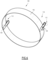
- the locking device 110 comprises for example at least one locking tab 112 attached to the cover 100, the locking tab 112 being configured for moving between an unlocking position ( Figure 6 ) and a locking position ( Figure 7 ) as a function of temperature.
- Each locking tab 112 is for example attached to the cover 100.
- Each locking tab 112 is for example stratified and comprises a first layer 114 made of a first metal having a first thermal expansion coefficient and a second layer 116 made of a second metal having a second thermal expansion coefficient, the first thermal expansion coefficient and the second thermal expansion coefficient being different.
- the first material is for example stainless steel and the second material is for example copper or brass.
- the first material has for example a thermal expansion coefficient comprised between 10.8 ⁇ 10 -6 /°C and 12.5 ⁇ 10 -6 /°C.
- the second material has for example a thermal expansion coefficient comprised between 16 ⁇ 10 -6 /°C and 19 ⁇ 10 -6 /°C, in particular between 16 ⁇ 10 -6 /°C and 16.7 ⁇ 10 -6 /°C (copper) or between 18 ⁇ 10 -6 /°C and 19 ⁇ 10 -6 /°C (brass).
- the first layer 114 and the second layer 116 are for example welded, soldered and/or glued together, in particular in a bottom area adjacent the cover.
- Each locking tab 112 is for example attached to the cover 100 such that the locking tab 112 is in register with a lateral opening 106 of the outer casing 96, the locking tab 112 in the unlocking position being retracted inside the outer casing 96 ( Figure 6 ) and the locking tab 112 in the locking position being extended towards the outside such as to interfere with an edge of the lateral opening 106 to prevent a movement of the cover 100 from the closed position to the open position.
- each locking tab 112 is in thermal contact with the heating plate 58, preferably via the heater tray 56 and/or the heater holder 54.
- each locking tab 112 is in thermal contact with the heating plate 58 via the heater tray 56 and the heater holder 54, in particular via the sliding portion 68 of the heater tray 56 and the guiding portion 66 of the heater holder 54.
- each locking tab 112 is located proximate a respective button 104 such as to interfere in the locking position with an edge of a lateral opening 106 in which said button 104 is received.
- a cartridge 4 is inserted in the cartridge housing 10 of the aerosol generating device 8 and a heating assembly 12 is inserted in the heater holder 54.
- the heating plate 58 of the heating assembly 12 is electrically connected to the battery 14 under control of the controller 16.
- the controller 16 activates the actuator 40 for pushing the piston 34 towards the front wall 32, thus increasing the pressure inside the chamber 30 whereby vaporizable material 6 is pushed out of the cartridge 4 via the valve 56 and collected in the heater cavity 60.
- the vaporizable released by the cartridge 4 is received in the heater cavity 40 with being in direct contact with the heating plate 58.
- the controller 16 powers the heating plate 58 to heat the vaporizable material 6 received in the heating cavity 64.
- the user can thus inhale air via the mouthpiece 22, the air circulating from the air inlets 18 to the aerosol outlet 20 with passing via the heating cavity 60 for collecting particles of vaporizable material 6 heated by the heating plate 58.
- the cover 100 is maintained in the closed position.
- the user moves the cover 100 in the open position by acting on one button 104.
- the user slides a new heating assembly 12 inside the heater holder 54 via the first opening, the old heating assembly 12 being automatically ejected from the heater holder 54 by being pushed out by the new heating assembly 12.
- the locking tab 112 Upon powering the heating plate 58, a fraction of the heat generated by the heating plate 58 is transferred to the locking tab 112. In case the user tries to move the cover 100 when the old heating assembly 12 is still hot, in particular too hot for being manipulated safely, the locking tab 112 remains in the locking position under the effect of the heat transferred from the heating plate 58 to the locking tab 112 thus preventing the user from moving the cover from the closed position towards the open position. When the heating plate 58 is cold enough, in particular cold enough for being manipulated safely, the locking tab 112 returns to the unlocking position thus allowing the user to move the cover 100 from the closed position towards the open position.
- the cartridge 4 does not integrate a heater and simple in design. Besides, in practice, a plurality of cartridges 4 can be used before replacing the heating assembly 12. The replacement is easy with the slide-in/slide out feature, even more when the new heating assembly is used to eject the old heating assembly.
- the cover 100 with the locking device 110 controlled as a function of the temperature of the heating plate 58 ensures a safe operation of the aerosol generating system 2 by the user.
Landscapes
- Containers And Packaging Bodies Having A Special Means To Remove Contents (AREA)
Abstract
A heating assembly for an aerosol generating device (8), the heating assembly comprising a heater tray (56) and a heating plate (58) mounted on an upper face of the heater tray (56), the heating assembly forming a replaceable unit of the aerosol generating device (8) and being configured for sliding in and sliding out of a heater holder (54) of the aerosol generating device (58).
Description
- The present invention relates to a heating assembly for an aerosol generating system configured to operate a cartridge containing vaporizable material.
- Consumable cartridges, also known as pods, are used in aerosol generating devices such as electronic cigarettes and vaping devices to provide a vaporizable material that is heated to generate an aerosol or vapour for inhalation by a user.
- The consumable cartridge generally includes a heating element and a wick that ensures liquid transmission from a reservoir to the heating element, the liquid being vaporized and mixed with an airflow coming from the exterior of the cartridge.
- However, the consumable cartridge is multipart and complicated. The cartridge is costly to manufacture and difficult to recycle after use. This impacts the sustainability of the use of the aerosol generating device.
- An aim of the present invention is to improve the sustainability of the aerosol generating device using a consumable cartridge, while making the operation of the aerosol generating device easy for the user.
- To this end, the invention proposes a heating assembly for an aerosol generating device, the heating assembly comprising a heater tray and a heating plate mounted on an upper face of the heater tray, the heating assembly forming a replaceable unit of the aerosol generating device, the heating assembly being configured for sliding in and sliding out of a heater holder of the aerosol generating device.
- The heating assembly configured to slide in and slide out of the aerosol generating device allows a more sustainable and a more economic use of the aerosol generating system as the heating assembly is separate from the cartridge (i.e. heating assembly is not integrated into the cartridge). The heating assembly is replaceable separately from the cartridge. Several cartridges can be used in the aerosol generating device before it is necessary to clean and/or replace the heating assembly. Slide in and sliding out the heating assembly from a heater holder provided in the aerosol generating device allows the operation of replacing the heating assembly to be operated easily by the user, with limited risk of error. A used or old heating assembly may potentially be slide out of the heater holder, then cleaned and then slide back in the heater holder.
- According to some embodiments, the heating assembly comprises heater electrical contacts mounted on the heater tray and electrically connected to the heating plate, the heater electrical contacts being configured for contacting corresponding holder electrical contacts of the heater holder upon sliding the heating assembly in the heater holder.
- Sliding the heating assembly into the heater holder makes the heater electrical contacts contact the holder electrical contacts. Mounting the heating assembly into the aerosol generating device is thus very easy for the user. The user does not have to take care of the electrical connection which is performed automatically upon insertion of the heating assembly into the heater holder.
- According to some embodiments, each heater electrical contact is mounted on a lower face of the heater tray.
- The arrangement of the heating plate on an upper face of the heater tray and the heater electrical contact on a lower face of the tray makes the manufacturing of the heating assembly easy. It also limits the risks of damaging the heating plate when sliding the heating assembly in the aerosol generating device or sliding the heating assembly out of the aerosol generating device since the electrical contact is to be made on the lower face of the heater tray opposite to the upper face of the heater tray receiving the heating plate.
- According to some embodiments, each heater electrical contact is electrically connected to the heating plate through the heater tray.
- This limits the risk of damaging the electrical connection between the heating plate and the heater electrical contacts, e.g. during handling the heating assembly and/or during insertion or extraction of the heating assembly in or out of the heater holder.
- According to some embodiments, each heater electrical contact is formed as metal plate, optionally provided with at least one dent for contact with a holder electrical contact.
- The heater electrical contact provided as a metal plate can be affixed easily to the lower face of the heater tray with little or no protrusion thus limiting any risk of damage during handling. It also allows providing a large contact area to ensure a reliable contact with the holder electrical contact. The optional dent allows a better location of the holder electrical contact relative to the heater electrical contact, thus creating a reliable electrical connection.
- According to some embodiments, the heating assembly is configured for sliding in and sliding out of the heater holder along a sliding axis and in a same sliding direction.
- This makes it possible to push an old heating assembly out of in the heater holder in sliding direction with a new heating assembly that is inserted in the heater holder to replace the old heating assembly.
- According to some embodiments, the heating assembly has a rotational symmetry of order two relative to a central axis.
- This allows the insertion of the heating assembly in two different orientations relative to the heater holder. This makes the use of the heating assembly for the user with limiting the risk of misuse.
- According to some embodiments, the heater tray of the heating assembly comprises at least one air intake, and preferably at least two air intakes. Each air intake is configured for providing air to the heating plate when the heating assembly is inserted in the aerosol generating device.
- The provision of at least one air intake in the heater tray allows providing the air stream in a controlled manner during the operation of the aerosol generating device. The provision of at least two air intakes allows providing the heating plate with air from two different points for a more uniform distribution of the air stream and an enhanced interaction with the vaporizable material heated by the heating plate.
- According to some embodiments, the upper face of the heater tray is provided with a cavity having a bottom surface, a side surface and a top opening, the heating plate being received in the cavity.
- The location of the heating plate in a cavity of the tray allows collecting an amount of vaporizable material released from a cartridge inside the cavity and heating this amount of vaporizable material in an appropriate manner with the heating plate. The top opening of the cavity preferably faces a dispensing outlet of the cartridge via which the vaporizable material is dispensed from the cartridge. Vaporizable material released in excess may be retained in the cavity and vaporized during a later use. The cavity thus limits the risk or leakage of vaporize vaporizable material. In addition, the heating plate being received in the cavity limits the risk of damaging the heating plate during handling of the heating assembly, in particular during sliding in or sliding out of the heater holder.
- Preferably, a surrounding region of the upper face of the heater tray, which surrounds the cavity, is in contact or in close proximity with the cartridge around the dispensing opening of the cartridge, when the heating assembly is received in the aerosol generating device. This limits the risk of leakage of vaporizable material in a gap between said surrounding region of the upper face and the cartridge.
- According to some embodiments, each air intake has an outlet opening in the cavity, the outlet of each air intake being preferably elevated relative to the bottom surface of the cavity.
- Each air intake opening in the cavity enables to provide air in an efficient manner to the cavity in which is located the heating plate and which receives vaporizable material during operation of the aerosol generating device. The elevated outlet of each air intake limits the risk of vaporizable material contained in the cavity leaking via the air intake.
- According to some embodiments, the heater tray comprises at least one air outtake, each air outtake being preferably elevated relative to the bottom surface of the cavity.
- Each air outtake allows the air containing vaporizable material heated by the heating plate (i.e. the aerosol) to exit the heater tray and to be conducted to an aerosol outlet of the aerosol generating device, which is provided in a mouth piece. The elevated outtake limits the risk of vaporizable material leaking via the outtake.
- According to some embodiments, each air outtake is formed as a notch or a groove on the upper face of the heater tray.
- Such an air outtake is easy to provide in the heater tray.
- According to some embodiments, the heater holder has a drain for draining vaporizable material leaking from the heating assembly.
- The drain allows evacuating vaporizable material that may have leaked from the heating assembly, e.g. from an air intake of the heating assembly, and to drain vaporizable material, e.g. to a collector for collecting vaporizable material. The collector may comprise a porous material configured for absorbing the vaporizable material.
- The invention also relates to an aerosol generating device comprising a heater holder configured for sliding in a heating assembly as defined above, the aerosol generating device being configured for operating the heating assembly received in the heater holder
- According to some embodiments, the aerosol generating device is configured such that a new heating assembly slid in the heater holder pushes an old heating assembly out of the heater holder.
- This makes the operation of replacing the old heating assembly very easy and ergonomic as the user only has to insert the new heating assembly, whereby the old heating assembly is automatically extracted or ejected.
- According to some embodiments, the aerosol generating device comprises a cover movable between a closed position in which the cover prevents insertion of the heating assembly in the heater holder and/or extraction of the heating assembly from the heater holder and an open position in which the cover allows insertion of the heating assembly in the heater holder and/or extraction of the heating assembly from the heater holder.
- The provision of the cover prevents air from entering in the aerosol generating device via an assembly opening for insertion or extraction of the heating assembly. It also prevents the user from touching or handling the heating assembly inadvertently.
- According to some embodiments, the aerosol generating device comprises a locking device configured for locking the cover in the closed position as a function of the temperature of the heater of the heating assembly received in the heater holder.
- This feature allows preventing the cover from opening as long as the temperature of the heating assembly is too high for the user to safely handling the heating assembly. This limits the risk that the user may get burned upon handling a heating assembly that has just been extracted from the aerosol generating device.
- The invention also relates to an aerosol generating system comprising a heating assembly as defined above, an aerosol generating device as defined above, and a cartridge containing a vaporizable material, the cartridge being receivable in use in the aerosol generating device and the aerosol generating device and heating assembly are configured such that when the heating assembly is inserted in the heater holder the heating plate is in direct contact with vaporizable material released from the cartridge so as to heat and vaporize vaporizable material delivered from the cartridge.
- The invention and its advantages will be better understood upon reading the following description, which is given by way of non-limiting example and which is made with reference to the appended drawings, in which:
-
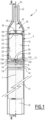
Figure 1 is a cross-sectional view of an aerosol generating device and a consumable cartridge received in the aerosol generating device; -
Figure 2 is another cross-sectional view of the aerosol generating device and a consumable cartridge received in the aerosol generating device taken along II - II onFigure 1 ; -
Figure 3 is an exploded perspective view of the cartridge along with a replaceable heating assembly and a heater holder of the aerosol generating device ofFigure 1 ; -
Figure 4 is another exploded perspective view of the cartridge the replaceable heating assembly and the heater holder taken from a different view angle; -
Figure 5 is a perspective view of the aerosol generating device illustrating the replacement of the replaceable heating assembly; -
Figure 6 is a perspective view of a locking member of a cover of the aerosol generating device; -
Figure 7 is a partial cross-sectional view of the aerosol generating device illustrating a cover in the closed position, a locking device of the cover being unlocked; and -
Figure 8 is a partial cross-sectional view similar to that ofFigure 6 , the locking device of the cover being locked. - Before describing the invention, it is to be understood that it is not limited to the details of construction set forth in the following description. It will be apparent to those skilled in the art having the benefit of the present disclosure that the invention is capable of other embodiments and of being practiced or being carried out in various ways.
- As used herein, the term "aerosol generating device" or "device" may include a vaping device to deliver an aerosol to a user, including an aerosol for vaping, by means of a heater element explained in further detail below. The device may be designed and configured to be handheld by a user, i.e. held and used within one hand of the user. The device may be adapted to generate a variable amount of aerosol, e.g. by activating the heater element for a variable amount of time (as opposed to a metered dose of aerosol), which can be controlled by a trigger. The trigger may be user activated, such as by a manual actuator located on an outer surface of the device (button or switch) and/or by means of an airflow or inhalation sensor arranged in the airflow path of the device. The inhalation sensor may be sensitive to the velocity of an airflow passing across the sensor during an inhalation by a user as well as the duration of inhalation to enable a variable amount of vapour to be provided (so as to mimic the effect of smoking a conventional combustible smoking article such as a cigarette, cigar or pipe, etc.). The device may include a temperature regulation control to adjust the temperature of the heater and/or of the heated aerosol generating substance (aerosol precursor) to a specified target temperature and thereafter to maintain the temperature at the target temperature that enables efficient generation of aerosol.
- As used herein, the term "aerosol" may include a suspension of vaporizable material as one or more of: solid particles; liquid droplets; gas. Said suspension may be in a gas including air. Aerosol herein may generally refer to/include a vapour. Aerosol may include one or more components of the vaporizable material.
- As used herein, the term "vaporizable material" or "precursor" may refer to a material which may comprise nicotine or tobacco and an aerosol former. Tobacco may take the form of various materials such as shredded tobacco, granulated tobacco, tobacco leaf and/or reconstituted tobacco, a liquid tobacco extract or solution comprising such. Suitable aerosol formers include: a polyol such as sorbitol, glycerol, and glycols like propylene glycol or triethylene glycol; a non-polyol such as monohydric alcohols, acids such as lactic acid, glycerol derivatives, esters such as triacetin, triethylene glycol diacetate, triethyl citrate, glycerin or vegetable glycerin. In some embodiments, the aerosol generating agent may be glycerol, propylene glycol, or a mixture of glycerol and propylene glycol. The substrate may also comprise at least one of a gelling agent, a binding agent, a stabilizing agent, and a humectant.
- As illustrated on
Figure 1 , anaerosol generating system 2 comprises acartridge 4 containing avaporizable material 6 and an aerosol generating device 8 configured to operate with saidcartridge 4 for producing an aerosol to be inhaled by a user. - The aerosol generating device 8 comprises a
cartridge housing 10 configured for receiving thecartridge 4 in a removable manner and aheating assembly 12 configured as a replaceable unit of the aerosol generating device 8 and arranged for receivingvaporizable material 6 released from thecartridge 4 and heating saidvaporizable material 6. The aerosol generating device 8 comprises for example abattery 14 for powering theheating assembly 12. The aerosol generating device 8 preferably comprises anelectric controller 16 configured for controlling thebattery 14 and theheating assembly 12. - The aerosol generating device 8 comprises for example at least one
air inlet 18 for feeding an airflow to theheating assembly 12 and anaerosol outlet 20 for delivering the airflow containing the aerosol generated at theheating assembly 12 to the user. Theaerosol outlet 20 is for example provided in amouthpiece 22 of the aerosol generating device 8. The aerosol generating device 8 is configured for the circulation of an air stream from theair inlet 18 to theaerosol outlet 20 with passing via theheating assembly 12 for collecting the heatedvaporizable material 6 in the air stream. - The
cartridge 4 comprises acartridge body 24 delimiting a cylinder 26 (Figure 4 ) extending along a cartridge axis B. Thecylinder 26 preferably has a circular cross-section. Thecartridge 4 comprises achamber 30 for storing thevaporizable material 6, thechamber 30 being delimited within thecylinder 26 between afront wall 32 and apiston 34 which is slidably received in thecylinder 26 such that sliding of thepiston 34 towards thefront wall 32 forces thevaporizable material 6 out of thechamber 30 via a dispensingopening 38. The dispensingopening 38 is in fluid communication with thechamber 30. The dispensingopening 38 is for example located on thefront wall 32, with being preferably centered on the cartridge axis B. - Advantageously, the vaporizable material is a gel with viscosity comprised between 5,000 cps and 50,000 cps at room temperature. The smoking gel could be achieved by increasing its viscosity and propylene glycol to vegetable glycerin ratio (or "PG/VG ratio) or adding food-grade thickener to the liquid. The food-grade thickener can be Xanthan gum.
- The
piston 34 is movable or operable by anactuator 40 of the aerosol generating device 8. Theactuator 40 is operable to move thepiston 34 within thecylinder 26 towards thefront wall 32 of thecartridge 4. Theactuator 40 comprises for example an axially movable pushingmember 42 configured for pushing thepiston 34 axially within thecylinder 26 and adrive unit 44 configured for driving the pushing member 36 axially. Theactuator 40 is preferably powered by thebattery 14 and controlled by thecontroller 16. - The pushing
member 42 and thedrive unit 44 cooperate for example via a screw/nut assembly. In such case, the pushingmember 42 comprises for example a threadedrod 45 and thedrive unit 44 comprises anut 46 engaged into the threadedrod 40 and amotor 48 for driving thenut 42 in rotation and thus driving the threadedrod 46 axially to push thepiston 34 towards thefront wall 32. - The
cartridge 4 optionally comprises arear wall 50 provided with arear opening 52 configured to receive the pushingmember 42 of theactuator 40 of the aerosol generating device 8 to operate thepiston 34. - The
heating assembly 12 is arranged in the aerosol generating device 8 in such a manner that theheating assembly 12 receivesvaporizable material 6 delivered from thecartridge 4, more precisely from the dispensingoutlet 38 of thecartridge 4, for heating thevaporizable material 6 and such that the air stream flowing from eachair inlet 18 to theair outlet 20 passes via theheating assembly 12 for collecting the heated vaporizedmaterial 6 and generating the aerosol. - The
heating assembly 12 is separate from thecartridge 4. Theheating assembly 12 is not integrated in thecartridge 4. Thecartridge 4 can be manufactured more easily and cost-effectively. The user can useseveral cartridges 4 with thesame heating assembly 12 which is more sustainable. - The
heating assembly 12 forms a replaceable unit of the aerosol generating device 8. Theheating assembly 12 is received in a removable manner in the aerosol generating device 8. Theheating assembly 12 formed as a replaceable unit renders the use of the aerosol generating device 8 more sustainable. A usedheating assembly 12 can be replaced with anew heating assembly 12. It is not necessary to replace the entire aerosol generating device 8 when theheating assembly 12 is worn. - The
heating assembly 12 forming a replaceable unit is configured for sliding in and sliding out aheater holder 54 of the aerosol generating device 8, preferably along a sliding axis A (Figure 2 ). - As illustrated on
Figures 3 and4 , theheating assembly 12 comprises aheater tray 56 and aheating plate 58 mounted on an upper face of theheater tray 56. Theheater tray 56 preferably comprises aheater cavity 60 formed in the upper face of theheater tray 56. Theheater cavity 60 is delimited by a bottom 62 and aside wall 64 extending upwardly from the bottom 62, the heating cavity having a top opening. Theheating plate 58 is received in theheater cavity 60. Theheater plate 58 is placed on the bottom 62 and is surrounded by theside wall 64. Theheating plate 58 is for example of circular contour. - The
heater tray 56 and theheater holder 54 are provided with complementary features for sliding theheater tray 56 in theheater holder 54 and out of theheater holder 54. Theheater holder 54 comprises for example at least one guidingportion 66 extending along the sliding axis A, theheater tray 56 comprising a respective slidingportion 68 associated to theguide portion 66, the slidingportion 68 being configured for sliding along theguide portion 66. Theheater holder 54 comprises for example abase plate 70 supporting twoguide portions 66 spaced transversely to the sliding axis A, theheater tray 56 being provided with two slidingportions 68 located on two opposed sides of theheater tray 56. Theheater tray 56 is slidable between the two guidingportions 66 with the two slidingportions 68 being engaged with the twoguide portions 66. Eachguide portion 66 comprises for example a female guiding part such as a groove and each slidingportion 68 comprises for example a male guiding part such as a rim, matching the female guiding part. In an alternative, eachguide portion 66 comprises for example a male guiding part such as a rim, each slidingportion 68 comprising a female guiding part matching the female guiding part. - Advantageously, the
heater tray 56 and theheater holder 54 are configured such that theheater tray 56 is slidable in theheater holder 54 and slidable out of theheater holder 54 in a first direction S1 along the sliding axis. This allows inserting theheater tray 56 and extracting theheater tray 56 in the same first direction S1. Optionally, theheater tray 56 and theheater holder 54 are configured such that theheater tray 56 is slidable in theheater holder 54 in a second direction S2 and/or and theheater tray 56 slidable out of theheater holder 54 in a second direction S2. The second direction S2 is opposed to the first direction S1 along the sliding axis A. - Alternatively, the
heater tray 56 and theheater holder 54 are configured such that theheater tray 56 is slidable in theheater holder 54 only in the first direction S1 and slidable out of theheater holder 54 only in the first direction S1. - Alternatively, the
heater tray 56 and theheater holder 54 are configured such that theheater tray 56 is slidable in theheater holder 54 only in the first direction S1 and slidable out of theheater holder 54 only in the second direction S2. - The
heater assembly 12 is configured such that when the heater assembly is inserted in the aerosol generating device, theheating plate 58 is in direct contact with vaporizable material released from thecartridge 4. - Preferably, as illustrated on
Figures 1 and2 , when theheating assembly 12 is received in the aerosol generating device 8, the dispensingopening 38 of thecartridge 4 opens in theheater cavity 60 and theheating plate 58 is in register with the dispensingopening 38. The upper face of theheater tray 56 faces for example thefront wall 32 of thecartridge 4, with the dispensingopening 38 being provided in thefront wall 32 and opening in theheater cavity 60. This ensure that thevaporizable material 6 released from the cartridge is collected in theheater cavity 60 for being in direct contact with theheating plate 58. - Preferably, when the
heating assembly 12 is received in the aerosol generating device 8, the upper face of theheater tray 56 is in contact or in close proximity with thefront face 32 of thecartridge 4. This limits the risk ofvaporizable material 6 released from thecartridge 4 from leaking from theheating cavity 60. - Back to
Figures 3 and4 , theheating plate 58 is for example provided with an electricalheat generating member 72 configured for generating heat when it is fed by electrical power, for example by Joule effect. The electricalheat generating member 72 is for example a resistor. The electricalheat generating member 72 is for example embedded in a bottom surface of theheating plate 58 and/or within the thickness of theheating plate 58. - The
heating assembly 12 comprises heaterelectrical contacts 74 mounted on theheater tray 56 with being electrically connected to theheating plate 58, more specifically here to the electricalheat generating member 72 of theheating plate 58. The heaterelectrical contacts 74 are configured for contacting corresponding holderelectrical contacts 76 of theheater holder 54 upon sliding theheating assembly 12 in theheater holder 54. Each heaterelectrical contact 74 is advantageously mounted on a lower face of theheater tray 56. Each heaterelectrical contact 74 is electrically connected to theheating plate 58, more specifically to the electricalheat generating member 72, through theheater tray 56. - Each heater
electrical contact 74 is advantageously formed as a metal plate, optionally provided with at least one dent 78 (Figure 4 ) for contact with a holderelectrical contact 76. The heaterelectrical contact 74 formed as a metal plate ensures a reliable contact with the holderelectrical contact 76 upon sliding in theheating assembly 12 in theheater holder 54. Each heaterelectrical contact 74 is preferably elongated in along the sliding axis A along which theheating assembly 12 is slide in and slide out of theheater holder 54. The provision of adent 78 allows a reliable contact and also allows locating theheater assembly 12 relative to theheater holder 54. It can also produce a haptic feedback to the user indicating that theheating assembly 12 is appropriately inserted in theheater holder 54. - Each holder
electrical contact 76 is for example a pin having apin base 79 attached to theheater holder 54 and apin head 80 protruding from theheater holder 54, in particular from abase plate 70 of theheater holder 54, for contacting the heaterelectrical contact 74. Thepin base 79 is electrically connected to thebattery 14. Each holderelectrical contact 76 extends for example through thebase plate 70 of theheater holder 54, with thepin head 80 protruding from thebase plate 70. - Each holder
electrical contact 76 is advantageously a pogo pin, i.e. a pin in which thepin head 80 is slidably movable relative to thepin base 79 with being urged by a spring (not visible) arranged between thepin base 79 and thepin head 80 to make contact with a heaterelectrical contact 74. As illustrated onFigure 3 , thepin head 80 is urged upwardly to contact the heaterelectrical contact 74 when theheating tray 56 is received in theheater holder 54. - The
heating assembly 12 is configured for the circulation of the air stream flowing around theheating plate 58 such as to create the aerosol formed of the air entraining the vaporizable material heated by theheating plate 58. - The
heating assembly 12 is in particular configured such that the air stream circulating in the aerosol generating device 8 from eachair inlet 18 to theair outlet 20 passes via theheater cavity 60 of theheater tray 56. - The
heater tray 56 comprises at least oneair intake 82 for feeding air to theheater cavity 60 and preferably at least twoair intakes 82 for feeding air to theheater cavity 60. Eachair intake 82 opens theheater cavity 60. Whenseveral air intakes 82 are provided, the air intakes 82 are for example uniformly distributed around theheating plate 58. In a particular example, theheater tray 56 comprises exactly twoair intakes 82 which are preferably located on opposed sides of theheating plate 58, i.e. diametrically opposed relative to theheating plate 58. Eachair intake 82 is for example located in arecess 84 provided in theside wall 64 of theheater cavity 60. The total area formed by the or all of the air intake(s) 82 is comprised for example between 0.25 mm2 and 3 mm2. This area defines the desired resistance to draw of the device. - Each
air intake 82 is preferably elevated relative to the bottom 62 of theheater cavity 60. This limits the risk of vaporizable material released from thecartridge 4 from flowing out of theheater cavity 60 via theair intake 82. Eachair intake 82 is for example located at a top end of a tube protruding upwardly from the bottom 62 of theheater cavity 60. - Each
air intake 82 is for example fluidly connected through theheater tray 56 to an air inlet opening 84 (Figure 4 ) located on the bottom face of theheater tray 56. Theheater holder 54 comprises for example one respectiveair inlet port 86 corresponding to eachair inlet opening 84 and in register with thisair inlet opening 84 when theheater tray 56 is received in theheater holder 54, such that theair inlet opening 84 is fed with air via theair inlet port 86. Eachair inlet port 86 is fluidly connected to theair inlet 18 of the aerosol generating device 8. - The
heater tray 56 comprises one orseveral air outtakes 88 for the air to flow out of theheater cavity 60. Eachair outtake 88 is in fluid communication with the air outlet of the aerosol generation device 8 when theheating assembly 12 is received in the aerosol generation device 8. Eachair outtake 88 comprises for example of one orseveral grooves 90 formed in the upper face of theheater tray 56, eachgroove 90 extending from theheater cavity 60 to a peripheral edge of the upper face. When theheating assembly 12 is received in theaerosol generating device 2 with the upper face of theheater tray 56 being proximate to the front face of thecartridge 4, eachgroove 90 defines for example a channel for the air stream to exit theheater cavity 60 towards theair outlet 20 of the aerosol generating device 8. Theheater tray 56 comprises for exampleseveral air outtakes 88 which are preferably uniformly distributed around theheater cavity 60. In a particular example, theheater tray 56 comprises twoair outtakes 88 which are preferably on opposed sides of theheater cavity 60, i.e. diametrically opposed relative to theheater cavity 60. - The
heater holder 54 advantageously comprises adrain 92. Thedrain 92 is configured for drainingvaporizable material 6 that may have leaked from theheater tray 56 to theheater holder 54, e.g. via anair intake 82. Thedrain 92 is provided for example as an opening extending through theheater holder 54, in particular through abase plate 70 of theheater holder 54. As visible onFigures 1 and2 , theaerosol generating device 2 comprises for example acollector 94 for collecting vaporizable material drained by thedrain 92. Thecollector 94 is located below thedrain 92. Thecollector 94 comprises for example a bloc of porous material for retaining the vaporizable material, e.g. by capillarity. - The
heater assembly 12 exhibits preferably a rotational symmetry of order two relative to a central axis C. This allows inserting theheater assembly 12 in theheater holder 54 in a first orientation around the central axis C or in a second orientation around the central axis C, the first orientation and the second orientation being separated by 180°. This makes the use of theheater assembly 12 easier for the user. - As illustrated on
Figure 5 , theheater assembly 12 is configured for sliding theheater assembly 12 in the heater holder 54 (not visible onFigure 5 ) in a first direction S1 along the sliding axis A and for sliding out of theheater holder 54 in said first direction S1 along the sliding axis A. - The aerosol generating device 8 is advantageously configured such that a new heater assembly 12 (at the top on
Figure 5 ) inserted in theheater holder 54 pushes an old heater assembly 12 (at the bottom onFigure 5 ) out of theheater holder 54. This makes the replacement of theold heater assembly 12 with anew heater assembly 12 very easy. - The aerosol generating device 8 comprises an
outer casing 96 in which theheater holder 54 is received. Theouter casing 96 is for example elongated along a longitudinal axis L and exhibits advantageously a symmetry of revolution around a longitudinal axis L. Themouthpiece 22 is for example provided at an extremity of theouter casing 96. Themouthpiece 22 has for example an outer diameter that is inferior to that of theouter casing 96. - The
outer casing 96 is provided with a first opening 98 (Figure 2 and5 ) for the insertion of theheating assembly 12 in theheater holder 54 and a second opening 99 (Figure 2 ) for the extraction of theheating assembly 12 out of theheater holder 54. Thefirst opening 98 and thesecond opening 99 provided on opposed sides of theouter casing 96. Upon insertion of anew heater assembly 12 in theheater holder 54 via thefirst opening 98, theold heater assembly 12 is pushed out of the aerosol generating device 8 via thesecond opening 99. - Optionally, the aerosol generating device 8 and the
heating assembly 12 are configured for insertion of theheating assembly 12 in theheater holder 54 via thesecond opening 99 and extraction of the heating assembly out of theheater holder 54 via thefirst opening 98. Upon insertion of anew heater assembly 12 in theheater holder 54 via thesecond opening 99, theold heater assembly 12 is pushed out of the aerosol generating device 8 via thefirst opening 98. - As illustrated on
Figures 1 ,2 and6 , the aerosol generating device 8 comprises advantageously acover 100 movable between a closed position in which the cover prevents insertion and/or extraction of theheating assembly 12 into or out of theheater holder 54 and an open position in which thecover 100 allows insertion and/or extraction of the heating assembly. Thecover 100 is for example slidable between the closed position and the open position. As illustrated onFigures 6 and7 , thecover 100 is to be move upwardly from the closed position (Figure 7 and8 ) to the open position (not illustrated). - Advantageously, the
cover 100 in the closed position closes the opening(s) of the aerosol generating device 8 configured for insertion in the aerosol generating device 8 and/or extraction of theheating assembly 12 out from the aerosol generating device 8, i.e. here thefirst opening 98 and thesecond opening 99. Thecover 100 thus prevents air from entering the aerosol generating device 8 via such openings, such that the air enters the aerosol generating device 8 via thededicated air inlets 18. - As illustrated in
Figure 6 , thecover 100 comprises anannular band 102 which is slidable within theouter casing 96 to selectively obstruct thefirst opening 98 and thesecond opening 99 for preventing insertion or extraction of anheating assembly 12 or move away from thefirst opening 98 and thesecond opening 99. - The
cover 100 is for example provided with at least onebutton 104 for allowing the user to manually drive thecover 100 between the closed position and the open position. Eachbutton 104 protrudes for example radially outwardly from theannular band 102. Thecover 100 is for example provided with two diametrically opposed buttons104. Eachbutton 104 is for example slidably received in a respective lateral opening 106 (Figures 1 ,5 ,7 and8 ) provided in theouter casing 96 such that the user can actuate thebutton 104 manually to slide thecover 100 relative to theouter casing 96. - The
aerosol generating device 2 advantageously comprises alocking device 110 configured for locking thecover 100 in the closed position as a function of the temperature of theheating plate 58 of theheating assembly 12 received in theheater holder 54. - The
locking device 110 comprises for example at least onelocking tab 112 attached to thecover 100, thelocking tab 112 being configured for moving between an unlocking position (Figure 6 ) and a locking position (Figure 7 ) as a function of temperature. Eachlocking tab 112 is for example attached to thecover 100. Eachlocking tab 112 is for example stratified and comprises afirst layer 114 made of a first metal having a first thermal expansion coefficient and asecond layer 116 made of a second metal having a second thermal expansion coefficient, the first thermal expansion coefficient and the second thermal expansion coefficient being different. - The first material is for example stainless steel and the second material is for example copper or brass. The first material has for example a thermal expansion coefficient comprised between 10.8 × 10⁻⁶/°C and 12.5 × 10⁻⁶/°C. The second material has for example a thermal expansion coefficient comprised between 16 × 10-6/°C and 19 × 10-6/°C, in particular between 16 × 10-6/°C and 16.7 × 10⁻⁶/°C (copper) or between 18 × 10-6/°C and 19 × 10-6/°C (brass). The
first layer 114 and thesecond layer 116 are for example welded, soldered and/or glued together, in particular in a bottom area adjacent the cover. - Each
locking tab 112 is for example attached to thecover 100 such that thelocking tab 112 is in register with alateral opening 106 of theouter casing 96, thelocking tab 112 in the unlocking position being retracted inside the outer casing 96 (Figure 6 ) and thelocking tab 112 in the locking position being extended towards the outside such as to interfere with an edge of thelateral opening 106 to prevent a movement of thecover 100 from the closed position to the open position. - As illustrated on
Figure 7 and8 , the aerosol generating device 8 is configured such that eachlocking tab 112 is in thermal contact with theheating plate 58, preferably via theheater tray 56 and/or theheater holder 54. In a particular example, each lockingtab 112 is in thermal contact with theheating plate 58 via theheater tray 56 and theheater holder 54, in particular via the slidingportion 68 of theheater tray 56 and the guidingportion 66 of theheater holder 54. - Advantageously, each locking
tab 112 is located proximate arespective button 104 such as to interfere in the locking position with an edge of alateral opening 106 in which saidbutton 104 is received. - In operation, a
cartridge 4 is inserted in thecartridge housing 10 of the aerosol generating device 8 and aheating assembly 12 is inserted in theheater holder 54. Theheating plate 58 of theheating assembly 12 is electrically connected to thebattery 14 under control of thecontroller 16. - In view of generating aerosol, the
controller 16 activates theactuator 40 for pushing thepiston 34 towards thefront wall 32, thus increasing the pressure inside thechamber 30 wherebyvaporizable material 6 is pushed out of thecartridge 4 via thevalve 56 and collected in theheater cavity 60. The vaporizable released by thecartridge 4 is received in theheater cavity 40 with being in direct contact with theheating plate 58. - Simultaneously, the
controller 16 powers theheating plate 58 to heat thevaporizable material 6 received in theheating cavity 64. The user can thus inhale air via themouthpiece 22, the air circulating from theair inlets 18 to theaerosol outlet 20 with passing via theheating cavity 60 for collecting particles ofvaporizable material 6 heated by theheating plate 58. - The
cover 100 is maintained in the closed position. When theheating assembly 12 needs to be replaced, the user moves thecover 100 in the open position by acting on onebutton 104. The user slides anew heating assembly 12 inside theheater holder 54 via the first opening, theold heating assembly 12 being automatically ejected from theheater holder 54 by being pushed out by thenew heating assembly 12. - Upon powering the
heating plate 58, a fraction of the heat generated by theheating plate 58 is transferred to thelocking tab 112. In case the user tries to move thecover 100 when theold heating assembly 12 is still hot, in particular too hot for being manipulated safely, thelocking tab 112 remains in the locking position under the effect of the heat transferred from theheating plate 58 to thelocking tab 112 thus preventing the user from moving the cover from the closed position towards the open position. When theheating plate 58 is cold enough, in particular cold enough for being manipulated safely, thelocking tab 112 returns to the unlocking position thus allowing the user to move thecover 100 from the closed position towards the open position. - Owing to the invention, it is possible to provide an
aerosol generating system 2 that is more economical to manufacture and to use, more sustainable and easy to use. Indeed, thecartridge 4 does not integrate a heater and simple in design. Besides, in practice, a plurality ofcartridges 4 can be used before replacing theheating assembly 12. The replacement is easy with the slide-in/slide out feature, even more when the new heating assembly is used to eject the old heating assembly. Thecover 100 with thelocking device 110 controlled as a function of the temperature of theheating plate 58 ensures a safe operation of theaerosol generating system 2 by the user.
Claims (15)
- A heating assembly for an aerosol generating device (8), the heating assembly comprising a heater tray (56) and a heating plate (58) mounted on an upper face of the heater tray (56), the heating assembly forming a replaceable unit of the aerosol generating device (8) and being configured for sliding in and sliding out of a heater holder (54) of the aerosol generating device (58).
- The heating assembly of claim 1, comprising heater electrical contacts (74) mounted on the heater tray (56) and being electrically connected to the heating plate (58), the heater electrical contacts (74) being configured for contacting corresponding holder electrical contacts (76) of the heater holder (56) upon sliding of the heating assembly (12) in the heater holder (56).
- The heating assembly of claim 2, wherein each heater electrical contact (74) is mounted on a lower face of the heater tray (56).
- The heating assembly of claim 2 or 3, wherein each heater electrical contact is formed as metal plate, optionally provided with at least one dent (78) for contact with a holder electrical contact (76).
- The heating assembly of any one of the preceding claims, wherein the heating assembly is configured for sliding in, respectively sliding out, of the heater holder along a sliding axis (A) in opposite first and second directions (S1, S2).
- The heating assembly of any one of the preceding claims, wherein the heating assembly (12) has a rotational symmetry of order two relative to a central axis (C).
- The heating assembly of any one of the preceding claims, wherein the heater tray (56) is provided with a heater cavity (60) having a bottom surface (62) and a side wall (64), the heating plate (58) being received in the cavity.
- The heating assembly of claim 7, wherein the heater tray (56) comprises at least one air intake (82) for providing air to the heating plate (58), and preferably at least two air intakes (82).
- The heating assembly of claim 8, wherein each air intake (82) opens in the heater cavity (60) with being preferably elevated relative to the bottom (62) of the heater cavity (60).
- The heating assembly of any one of claims 7-9, wherein the heater tray (56) comprises at least one air outtake (88), each air outtake (88) opening in the heater cavity (60), each air outtake (88) being preferably elevated relative to the bottom (62) of the heater cavity (60), each air outtake (10) advantageously comprising at least one notch or groove formed in the upper face of the heater tray (56).
- An aerosol generating device comprising a heater holder (54) configured for sliding in a heating assembly (12) as in any one of the preceding claims, the aerosol generating device being configured for operating the heating assembly (12) received in the heater holder (54).
- The aerosol generating device according to claim 11, configured such that a new heating assembly (12) inserted in the heater holder (54) pushes an old heating assembly (12) out of the heater holder (54).
- The aerosol generating device according to claim 11 or 12, comprising a cover (100) movable between a closed position in which the cover prevents insertion and/or extraction of the heating assembly (12) and an open position in which the cover allows insertion and/or extraction of the heating assembly (12).
- The aerosol generating device according to claim 13, comprising a locking device (110) configured for locking the cover (100) in the closed position as a function of the temperature of the heating plate (58) of the heating assembly (12) received in the heater holder (54).
- An aerosol generating system comprising:- a heating assembly (12) according to any one of claims 1-10,- an aerosol generating (8) device according to any one of claim 11 - 14, and- a cartridge (4) containing a vaporizable material (6),the cartridge being receivable in use in the aerosol generating device and the aerosol generating device and heating assembly are configured such that when the heating assembly is inserted in the heater holder (54) the heating plate (58) is in direct contact with vaporizable material (6) released from the cartridge (4) so as to heat and vaporize vaporizable material (6) delivered from the cartridge (4).
Priority Applications (1)
| Application Number | Priority Date | Filing Date | Title |
|---|---|---|---|
| EP23168482.0A EP4449920A1 (en) | 2023-04-18 | 2023-04-18 | A heating assembly for an aerosol generating device and a corresponding aerosol generating device |
Applications Claiming Priority (1)
| Application Number | Priority Date | Filing Date | Title |
|---|---|---|---|
| EP23168482.0A EP4449920A1 (en) | 2023-04-18 | 2023-04-18 | A heating assembly for an aerosol generating device and a corresponding aerosol generating device |
Publications (1)
| Publication Number | Publication Date |
|---|---|
| EP4449920A1 true EP4449920A1 (en) | 2024-10-23 |
Family
ID=86053757
Family Applications (1)
| Application Number | Title | Priority Date | Filing Date |
|---|---|---|---|
| EP23168482.0A Pending EP4449920A1 (en) | 2023-04-18 | 2023-04-18 | A heating assembly for an aerosol generating device and a corresponding aerosol generating device |
Country Status (1)
| Country | Link |
|---|---|
| EP (1) | EP4449920A1 (en) |
Citations (3)
| Publication number | Priority date | Publication date | Assignee | Title |
|---|---|---|---|---|
| US20170143042A1 (en) * | 2014-07-11 | 2017-05-25 | Philip Morris Products S.A. | Aerosol-generating system comprising a removable heater |
| WO2018051346A1 (en) * | 2016-09-14 | 2018-03-22 | Yossef Raichman | Smoking device |
| KR20230015377A (en) * | 2020-05-22 | 2023-01-31 | 제이티 인터내셔널 소시에떼 아노님 | aerosol generating device |
-
2023
- 2023-04-18 EP EP23168482.0A patent/EP4449920A1/en active Pending
Patent Citations (3)
| Publication number | Priority date | Publication date | Assignee | Title |
|---|---|---|---|---|
| US20170143042A1 (en) * | 2014-07-11 | 2017-05-25 | Philip Morris Products S.A. | Aerosol-generating system comprising a removable heater |
| WO2018051346A1 (en) * | 2016-09-14 | 2018-03-22 | Yossef Raichman | Smoking device |
| KR20230015377A (en) * | 2020-05-22 | 2023-01-31 | 제이티 인터내셔널 소시에떼 아노님 | aerosol generating device |
Similar Documents
| Publication | Publication Date | Title |
|---|---|---|
| EP3654787B1 (en) | Shisha device for enhanced aerosol characteristics | |
| JP7056995B2 (en) | Electronic aerosol supply device | |
| US12342861B2 (en) | Aerosol-generating system and article for use therewith | |
| KR102525780B1 (en) | Aerosol-generating articles and aerosol-generating devices comprising pistons | |
| JP7131610B2 (en) | electronic aerosol delivery device | |
| EP3119220B1 (en) | An inhaler | |
| EP3062645B2 (en) | Aerosol delivery device including a positive displacement aerosol delivery mechanism | |
| EP4069010B1 (en) | Cartridge insertion systems for aerosol-generating devices | |
| TW202243603A (en) | Aerosol generating device comprising a pushing bar | |
| EP3945896B1 (en) | Aerosol delivery device | |
| EP4069009B1 (en) | Aerosol-generating device with piercing assembly | |
| EP3945901B1 (en) | Smoking substitute system | |
| CN224192938U (en) | Aerosol generating device | |
| CN112998323A (en) | Humidification device and electron cigarette | |
| EP4602944A1 (en) | Method of manufacturing an aerosol generating apparatus | |
| EP4197355B1 (en) | Aerosol delivery component | |
| EP4449916A1 (en) | A cartridge comprising a piston and a valve and an associated aerosol generating system | |
| EP4447728B1 (en) | Holder for supporting a vaporiser in an aerosol delivery system | |
| EP4573940A1 (en) | An aerosol generating cartridge for an aerosol generating device, and associated aerosol generating device | |
| EP4573937A1 (en) | An aerosol generating device, and associated aerosol generating system | |
| KR20250007782A (en) | AEROSOL GENERATOR with cigarette extraction function | |
| CN120570424A (en) | Aerosol supply device | |
| HK1227259A1 (en) | Aerosol delivery device including a positive displacement aerosol delivery mechanism | |
| HK1227259B (en) | Aerosol delivery device including a positive displacement aerosol delivery mechanism |
Legal Events
| Date | Code | Title | Description |
|---|---|---|---|
| PUAI | Public reference made under article 153(3) epc to a published international application that has entered the european phase |
Free format text: ORIGINAL CODE: 0009012 |
|
| STAA | Information on the status of an ep patent application or granted ep patent |
Free format text: STATUS: THE APPLICATION HAS BEEN PUBLISHED |
|
| AK | Designated contracting states |
Kind code of ref document: A1 Designated state(s): AL AT BE BG CH CY CZ DE DK EE ES FI FR GB GR HR HU IE IS IT LI LT LU LV MC ME MK MT NL NO PL PT RO RS SE SI SK SM TR |
|
| STAA | Information on the status of an ep patent application or granted ep patent |
Free format text: STATUS: REQUEST FOR EXAMINATION WAS MADE |
|
| 17P | Request for examination filed |
Effective date: 20250324 |