EP4449912A1 - Consumables loading system for aerosol-generating device - Google Patents
Consumables loading system for aerosol-generating device Download PDFInfo
- Publication number
- EP4449912A1 EP4449912A1 EP23168200.6A EP23168200A EP4449912A1 EP 4449912 A1 EP4449912 A1 EP 4449912A1 EP 23168200 A EP23168200 A EP 23168200A EP 4449912 A1 EP4449912 A1 EP 4449912A1
- Authority
- EP
- European Patent Office
- Prior art keywords
- magazine
- aerosol
- receptacle
- generating device
- consumable
- Prior art date
- Legal status (The legal status is an assumption and is not a legal conclusion. Google has not performed a legal analysis and makes no representation as to the accuracy of the status listed.)
- Withdrawn
Links
Images




Classifications
-
- A—HUMAN NECESSITIES
- A24—TOBACCO; CIGARS; CIGARETTES; SIMULATED SMOKING DEVICES; SMOKERS' REQUISITES
- A24F—SMOKERS' REQUISITES; MATCH BOXES; SIMULATED SMOKING DEVICES
- A24F40/00—Electrically operated smoking devices; Component parts thereof; Manufacture thereof; Maintenance or testing thereof; Charging means specially adapted therefor
- A24F40/30—Devices using two or more structurally separated inhalable precursors, e.g. using two liquid precursors in two cartridges
-
- A—HUMAN NECESSITIES
- A24—TOBACCO; CIGARS; CIGARETTES; SIMULATED SMOKING DEVICES; SMOKERS' REQUISITES
- A24F—SMOKERS' REQUISITES; MATCH BOXES; SIMULATED SMOKING DEVICES
- A24F40/00—Electrically operated smoking devices; Component parts thereof; Manufacture thereof; Maintenance or testing thereof; Charging means specially adapted therefor
- A24F40/40—Constructional details, e.g. connection of cartridges and battery parts
-
- A—HUMAN NECESSITIES
- A24—TOBACCO; CIGARS; CIGARETTES; SIMULATED SMOKING DEVICES; SMOKERS' REQUISITES
- A24F—SMOKERS' REQUISITES; MATCH BOXES; SIMULATED SMOKING DEVICES
- A24F40/00—Electrically operated smoking devices; Component parts thereof; Manufacture thereof; Maintenance or testing thereof; Charging means specially adapted therefor
- A24F40/40—Constructional details, e.g. connection of cartridges and battery parts
- A24F40/42—Cartridges or containers for inhalable precursors
Definitions
- the present disclosure relates to a system comprising an aerosol-generating device with a magazine for storing consumables and a loading mechanism for transferring a consumable from the magazine to the aerosol-generating device.
- Such aerosol-generating articles may comprise an aerosol-generating substrate that generates an aerosol when heated, one or more aerosol-cooling elements, and optionally a filter to prevent passage of debris from the aerosol-generating substrate.
- the aerosol-generating substrate may comprise a crimped and gathered sheet of tobacco cast leaf material, or any other substrate made of or impregnated with a substance that generates a desired aerosol upon application of heat.
- a user therefore needs to carry not just the aerosol-generating device, but also a supply of consumables, for example in the form of one or more packets of such consumables. Moreover, if no proper used consumable disposal facilities are available, the user may need temporarily to carry used consumables in the packet of unused consumables. Some used consumables may have an undesirable aroma that may be transferred to unused consumables in the packet.
- a system comprising:
- Embodiments of the present invention allow a user to keep a plurality of fresh consumables in the magazine, one consumable in each receptacle of the plurality of receptacles of the magazine.
- a user wishes to enjoy a consumable, they can operate the loading mechanism to transfer a fresh consumable from one of the plurality of receptacles of the magazine to the receptacle of the aerosol-generating device.
- aerosol-generating device can be activated to generate an aerosol for enjoyment by the user.
- embodiments of the present invention enable a plurality of fresh consumables to be carried integrally with the system, and the user may not need to carry a separate packet of fresh consumables.
- a used consumable may be transferred from the receptacle of the aerosol-generating device back into an empty receptacle of the plurality of receptacles of the magazine. This provides a convenient storage of used consumables for later disposal in an environmentally friendly manner. Provided that the plurality of receptacles of the magazine are separated from each other, potential contamination of fresh consumables by used consumables can be avoided.
- Another advantage is that a user may load the plurality of receptacles of the magazine with different types of consumable, thereby providing a choice of consumable without the need to carry different packets of different types of consumables.
- the magazine may be rotatable about a longitudinal axis so as to enable receptacles of the magazine to be individually aligned with the receptacle of the aerosol-generating device.
- a magazine may be loaded with consumables, for example one consumable in each receptacle, and the magazine may be rotated about the longitudinal axis so that a receptacle of the magazine is aligned with the receptacle of the chamber, permitting the consumable to be transferred longitudinally from the receptacle of the magazine to the receptacle of the chamber.
- the loading mechanism may be configured to transfer a consumable from the receptacle of the magazine to the receptacle of the aerosol-generating device when the receptacle of the magazine is aligned with the receptacle of the aerosol-generating device.
- the loading mechanism may be a manually operated mechanism.
- the loading mechanism may comprise a sliding mechanism with a member on the outside of the aerosol-generating device that can be reciprocated in the direction of the longitudinal axis by a user's thumb or finger, and a member that extends into the receptacle of the magazine and is moveable with the external member to push the consumable from the receptacle of the magazine to the receptacle of the aerosol-generating device when the receptacle of the magazine is aligned with the receptacle of the aerosol-generating device.
- the loading mechanism may comprise a rack and pinion mechanism with a toothed thumbwheel accessible from the outside of the aerosol-generating device that can be rotated to move a toothed rack in the direction of the longitudinal axis, and a member that extends into the receptacle of the magazine and is moveable with the toothed rack to push the consumable from the receptacle of the magazine to the receptacle of the aerosol-generating device when the receptacle of the magazine is aligned with the receptacle of the aerosol-generating device
- the loading mechanism may be a motorised mechanism.
- the loading mechanism may comprise an electric motor configured to move a member that extends into the receptacle of the magazine to push the consumable from the receptacle of the magazine to the receptacle of the aerosol-generating device when the receptacle of the magazine is aligned with the receptacle of the aerosol-generating device.
- the electric motor may be activated by a switch on the aerosol-generating device, for example a button that can be pressed by a user.
- There may be provided circuitry that only allows the electric motor to be activated when the when the receptacle of the magazine containing the consumable is aligned with the receptacle of the aerosol-generating device.
- the circuitry may comprise electrical contacts on the aerosol-generating device and electrical contacts on the magazine that only contact each other when the receptacle of the magazine containing the consumable is aligned with the receptacle of the aerosol-generating device. This can help to prevent activation of the electric motor when the magazine is not properly rotationally aligned with the aerosol-generating device, and can thus help to prevent jamming.
- the magazine may be displaceable relative to the aerosol-generating device so as to allow consumables to be filled into or removed from the receptacles of the magazine.
- the magazine may be displaced from the aerosol-generating device in a direction substantially perpendicular to the longitudinal axis.
- the magazine may be entirely removable from the aerosol-generating device.
- the magazine may be displaceable by a predetermined amount but prevented from being displaced beyond this amount by way of a stopping mechanism.
- the magazine may be hingedly connected to the aerosol-generating device.
- the magazine may be hingedly connected to the aerosol-generating device about an axis that is substantially parallel to the longitudinal axis.
- the hinged connection may be located at or close to a circumferential edge of the magazine.
- the system may further comprise an aerosol-generating unit for generating aerosol from the consumable(s).
- the aerosol-generating unit may be a heating unit configured to heat the consumable so as to generate the aerosol.
- the heating unit may be provided in the aerosol-generating device.
- the heating unit may be provided in the consumable.
- the aerosol-generating device may comprise at least one component of the heating unit while the consumable comprises at least one other component of the heating unit.
- the heating unit may be activatable by a user.
- the heating unit may be activated by a switch on the aerosol-generating device, for example a button that can be pressed by a user.
- the heating unit may be an inductive heating unit.
- An induction coil connectable to a power supply may be provided in the aerosol-generating device.
- the induction coil may be disposed adjacent to or surrounding the receptacle of the aerosol-generating device.
- the consumable may comprise a susceptor, for example a metal element, which is configured to be heated when exposed to an alternating electromagnetic field by the induction coil.
- the heating unit may be a resistive heating unit.
- An electrically resistive element connectable to a power supply may be provided in the aerosol-generating device.
- the electrically resistive element may be disposed adjacent to or surrounding the receptacle of the aerosol-generating device.
- the electrically resistive element may be configured to penetrate the consumable when the consumable is in the receptacle of the aerosol-generating device.
- the electrically resistive element may be configured to contact the consumable when the consumable is in the receptacle of the aerosol-generating device.
- the heating unit may be a microwave heating unit, or a dielectric heating unit.
- the aerosol-generating device may generate an aerosol by subjecting the consumable to ultrasonic vibrations.
- the aerosol-generating device may comprise an ultrasonic transducer connectable to a power supply and configured to direct ultrasonic vibrations at or to the consumable when the consumable is in the receptacle of the aerosol-generating device.
- the ultrasonic transducer may be activated by a switch on the aerosol-generating device, for example a button that can be pressed by a user.
- the receptacle of the aerosol-generating device may comprise a chamber having a first open end to receive a consumable from an aperture of the magazine, and a second open end from which a mouthpiece end of the consumable projects when the consumable is fully loaded into the receptacle of the aerosol-generating device.
- the chamber may be substantially cylindrical.
- the loading mechanism may be further configured to eject a used consumable from the receptacle of the aerosol-generating device, through the second open end of the chamber, when a fresh consumable is transferred from a receptacle of the magazine to the receptable of the aerosol-generating device through the first open end of the chamber.
- the fresh consumable may in effect be used to push the used consumable out through the second open end of the chamber, and the user can then dispose of the used consumable in a responsible manner.
- the first open end of the chamber may be provided with a substantially airtight cover that is moveable between an open position, allowing communication with a receptacle of the magazine so as to allow a consumable to be loaded into the chamber, and a closed position, sealing the first open end of the chamber.
- a substantially airtight cover When the substantially airtight cover is in the closed position, the receptacles of the magazine may be isolated from external atmosphere. This can help to keep unused consumables in the receptacles of the magazine fresh.
- the second open end of the chamber may be provided with a substantially airtight cover that is moveable between an open position, allowing the mouthpiece end of the consumable loaded into the chamber to project from the aerosol-generating device, and a closed position, sealing the second open end of the chamber when no consumable is loaded into the chamber.
- This can help to prevent ingress of air into the receptacle of the aerosol-generating device and thence into the receptacles of the magazine when the aerosol-generating device is not being used for generating an aerosol. This can help to keep unused consumables in the receptacles of the magazine fresh.
- the loading mechanism may be further configured to transfer a consumable from the receptacle of the aerosol-generating device to a receptacle of the magazine.
- a used consumable may be transferred from the receptacle of the aerosol-generating device back into an empty receptacle of the magazine for temporary storage until the magazine can be conveniently emptied of used consumables and the used consumables disposed of in a responsible manner.
- the receptacles of the magazine may be substantially sealed from external atmosphere when not aligned with the receptacle of the aerosol-generating device and when the magazine is not displaced from the aerosol-generating device for loading with consumables. This can help to keep unused consumables in the receptacles of the magazine fresh.
- the receptacles of the magazine may be substantially sealed from external atmosphere by a cover that is moveable between open and closed positions.
- An end of the receptacle of the aerosol-generating device closest to the magazine may be provided with an air inlet to allow air to be drawn through a consumable received in the receptacle of the aerosol-generating device.
- the air inlet may comprise a one-way valve. In this way, air flow through the consumable may be controlled, with air only passing through the consumable when a user draws on a mouthpiece end of the consumable. Provision of a one-way valve may further help to reduce exposure of unused consumables in receptacles of the magazine to air, thus helping to keep the unused consumables fresh.
- the receptacles of the magazine may be transparent or may comprise windows to allow consumables held within the receptacles of the magazine to be viewed from outside the magazine. This allows a user to determine how many unused consumables are available in the magazine, and whether or not the magazine might need to be refilled.
- a user may load the magazine with an assortment of different consumables (for example of different strengths or flavours), and the user can then easily select a desired consumable for enjoyment by aligning the receptacle of the magazine containing the desired consumable with the receptacle of the aerosol-generating device and activating the loading mechanism.
- Different types of consumables may be provided with distinguishing indicia, for example different colours or markings, in order to facilitate selection.
- the loading mechanism may be operatively connected to the heating unit so as to activate the heating unit when a consumable is fully loaded into the receptacle of the aerosol-generating device.
- the loading mechanism may be operatively connected to the ultrasonic transducer so as to activate the ultrasonic transducer when a consumable is fully loaded into the receptacle of the of aerosol-generating device.
- the aerosol-generating device may automatically start to generate an aerosol from the consumable when the consumable is fully loaded into the receptacle of the aerosol-generating device.
- the heating unit or the ultrasonic transducer may automatically switch off again after a predetermined period of time.
- a magazine for use with an aerosol-generating device comprising a cavity configured to receive and retain the magazine at least partially within the aerosol-generating device; wherein the magazine comprises a plurality of receptacles each holding or configured to receive a consumable to be loaded into the aerosol-generating device.
- the aerosol-generating device may comprise a receptacle configured to receive a consumable from the magazine, and the aerosol-generating device may be configured to generate an aerosol from the consumable located at least partially in the receptacle.
- the magazine may be rotatable about a longitudinal axis.
- the longitudinal axis of the magazine may be aligned with a longitudinal axis of the aerosol-generating device when the magazine is coupled with the aerosol-generating device.
- the longitudinal axis may be a substantially central longitudinal axis of rotation.
- the longitudinal axis may be an axis of substantial rotational symmetry.
- the magazine may be configured to be engageable with the aerosol-generating device in such a way that the magazine is rotatable about the longitudinal axis when engaged with the aerosol-generating device.
- the magazine may be rotatable about a longitudinal axis so as to align the receptacles of the magazine individually with the receptacle of the aerosol-generating device such that a consumable within the aligned receptacle of the magazine can be transferred from the aligned receptacle of the magazine to the receptacle of the aerosol-generating device by a loading mechanism.
- the receptacles of the magazine may comprise a plurality of chambers arranged substantially parallel to the longitudinal axis. Each one of the chambers may be at least partially cylindrical.
- the receptacles of the magazine may be arranged in a circle around the longitudinal axis and substantially parallel to the longitudinal axis and to each other.
- the magazine may comprise a drum-shaped body with the receptacles disposed adjacent to a circumferential surface of the drum-shaped body.
- the receptacles may each comprise an open longitudinal slot at the circumferential surface of the drum-shaped body.
- the open longitudinal slot permits a member of a loading mechanism provided in the aerosol-generating device to extend into the receptacle of the magazine and to push a consumable out of the receptacle of the magazine and into an aligned receptacle of the aerosol-generating device.
- the magazine may comprise a top surface substantially perpendicular to the longitudinal axis and a bottom surface substantially perpendicular to the longitudinal axis.
- the magazine may be substantially drum-shaped.
- Either the top surface or the bottom surface or both of the top surface and the bottom surface may be provided with a central projection or indentation to releasably engage with corresponding indentations or projections on the aerosol-generating device. This facilitates rotation of the magazine about the longitudinal axis when engaged with the aerosol-generating device while helping to prevent the magazine from becoming inadvertently disengaged from the aerosol-generating device. Additional projections, indentations, or projections and indentations may be provided in a substantially circular arrangement about the longitudinal axis on the top surface or the bottom surface or both the top surface and the bottom surface.
- Additional projections, indentations, or projections and indentations may be positioned to engage with corresponding features on the aerosol-generating device whenever a receptacle of the magazine is correctly aligned with the receptacle of the aerosol-generating device. This can provide a haptic indication to a user when a receptacle of the magazine is correctly aligned with the receptacle of the aerosol-generating device so as to allow a consumable to be transferred from the receptacle of the magazine to the receptacle of the aerosol-generating device.
- the magazine may be made of a substantially transparent material.
- the magazine may be made of a substantially transparent plastics material.
- the magazine may be provided (or sold) separately from the aerosol-generating device.
- the magazine may be provided (or sold) pre-loaded with consumables.
- a user may simply insert a new pre-loaded magazine into the aerosol-generating device when the user has run out of consumables.
- the old magazine which may be empty or may contain used consumables that have been transferred back into the receptacles of the magazine after use, may be returned to the retailer or manufacturer for recycling, together with the used consumables where appropriate.
- Pre-loaded magazines may be packaged in airtight packaging. In embodiments where the receptacles of the magazine are isolated from ambient air when the magazine is loaded into the aerosol-generating device, exposure of consumables to atmosphere can be much reduced. This can help to maintain freshness of the consumables.
- a loading mechanism for loading consumables into a receptacle of an aerosol-generating device from one of a plurality of receptacles of a magazine each configured to receive a consumable
- the loading mechanism comprises a member operable to push a consumable from one of the plurality of receptacles of the magazine into the receptacle of the aerosol-generating device when the one of the plurality of receptacles is longitudinally aligned with the receptacle of the aerosol-generating device by rotating the magazine relative to the aerosol-generating device.
- the loading mechanism may comprise a portion that is located on an exterior portion of the aerosol-generating device, the portion being connected to the member, and the portion being configured to be manually displaced in a direction substantially parallel to a longitudinal axis of the one of the plurality of receptacles of the magazine so that the member is also displaced along the one of the plurality of receptacles of the magazine.
- the portion on the exterior portion of the aerosol-generating device may be a slider operable by a user's thumb or finger.
- the portion may comprise a toothed wheel that is rotatable, for example by way of a user's thumb, so as to displace a toothed rack in the direction substantially parallel to the longitudinal direction.
- the toothed rack may be contained within a body of the aerosol-generating device.
- the loading mechanism may comprise a motor, the motor being operable to displace the member, and the member being configured to be displaced by the motor in a direction along a longitudinal axis of the one of the plurality of receptacles of the magazine.
- the motor may be an electric motor.
- the electric motor may be activated by a switch on the aerosol-generating device, for example a button that can be pressed by a user.
- There may be provided circuitry that only allows the electric motor to be activated when the when the receptacle of the magazine containing the consumable is aligned with the receptacle of the aerosol-generating device.
- the circuitry may comprise electrical contacts on the aerosol-generating device and electrical contacts on the magazine that only contact each other when the receptacle of the magazine containing the consumable is aligned with the receptacle of the aerosol-generating device. This can help to prevent activation of the electric motor when the magazine is not properly rotationally aligned with the aerosol-generating device, and can thus help to prevent jamming.
- the loading mechanism may comprise a gearing mechanism configured to move a substantially airtight cover at one or other or both ends of the receptacle of the aerosol-generating device between closed and open positions so as to allow the consumable to be pushed from the one of the receptacles of the magazine into the receptacle of the aerosol-generating device.
- a gearing mechanism configured to move a substantially airtight cover at one or other or both ends of the receptacle of the aerosol-generating device between closed and open positions so as to allow the consumable to be pushed from the one of the receptacles of the magazine into the receptacle of the aerosol-generating device.
- the magazine may comprise a drum-shaped body with the receptacles of the magazine disposed adjacent to a circumferential surface of the drum-shaped body, wherein the receptacles of the magazine each comprise an open longitudinal slot at the circumferential surface of the drum-shaped body, and wherein the member is configured to project through the open longitudinal slot of one of the receptacles of the magazine when the consumable is pushed from the one of the receptacles of the magazine into the receptacle of the aerosol-generating device.
- a method of loading a consumable into a receptacle of an aerosol-generating device wherein a magazine comprising a plurality of receptacles each containing a consumable is displaceably connected to the aerosol-generating device, the magazine is displaced relative to the aerosol-generating device so as longitudinally to align one of the plurality of receptacles of the magazine with the receptacle of the aerosol-generating device, and wherein a loading mechanism is operated to push a consumable from aligned receptacle of the magazine to the receptacle of the aerosol-generating device.
- the magazine may be rotatably displaceable relative to the aerosol-generating device.
- the magazine may be rotatable displaceable relative to the aerosol-generating device in the manner hereinbefore described.
- the loading mechanism may be manually operated.
- the loading mechanism may be operated by a user moving a slider on an outside of the aerosol-generating device with a thumb or finger.
- the loading mechanism may be operated by a user rotating a toothed wheel projecting at an outside of the aerosol-generating device with a thumb or finger.
- the loading mechanism may comprise a member that projects into the aligned one of the plurality of receptacles of the magazine and an external slider connected to the member, and the external slider may be manually moved in a direction parallel to a longitudinal axis of the aligned one of the plurality of receptacles of the magazine so as to cause the member to push the consumable from the aligned one of the plurality of receptacles of the magazine into the receptacle of the aerosol-generating device.
- the loading mechanism may be operated by a user rotating a toothed wheel projecting at an outside of the aerosol-generating device with a thumb or finger.
- the loading mechanism may comprise a member that projects into the aligned one of the plurality of receptacles of the magazine and a toothed rack that is engaged by the toothed wheel, and the toothed wheel may be manually rotated so as to move the toothed rack in a direction parallel to a longitudinal axis of the aligned one of the plurality of receptacles of the magazine so as to cause the member to push the consumable from the aligned one of the plurality of receptacles of the magazine into the receptacle of the aerosol-generating device.
- the loading mechanism may be driven by a motor.
- the motor may be an electric motor.
- the loading mechanism may comprise a member that projects into the aligned one of the plurality of receptacles of the magazine, and the member may be driven by the motor in a direction parallel to a longitudinal axis of the aligned one of the plurality of receptacles of the magazine so as to cause the member to push the consumable from the aligned one of the plurality of receptacles of the magazine into the receptacle of the aerosol-generating device.
- the loading mechanism may comprise a gearing mechanism and the gearing mechanism may move a substantially airtight cover at one or other or both ends of the receptacle of the aerosol-generating device between closed and open positions so as to allow the consumable to be pushed from the one of the receptacles of the magazine into the receptacle of the aerosol-generating device.
- the magazine may be hingedly connected to the aerosol-generating device and moveable between an engaged position in which all of the receptacles of the magazine are covered by the aerosol-generating device and a loading position in which the receptacles of the magazine are exposed, and wherein consumables are loaded into the magazine when the magazine is in the loading position.
- the aerosol-generating device may comprise a heating unit operable to heat the consumable when loaded into the receptacle of the aerosol-generating device.
- the heating unit may be activated by the loading mechanism when the consumable is pushed into the receptacle of the aerosol-generating device.
- the aerosol-generating device may comprise an ultrasonic transducer operable to direct ultrasonic vibrations to or at the consumable when loaded into the receptacle of the aerosol-generating device.
- the ultrasonic transducer may be activated by the loading mechanism when the consumable is pushed into the receptacle of the aerosol-generating device.
- a consumable may be transferred from the receptacle of the aerosol-generating device into an empty aligned one of the receptacles of the magazine after the consumable has been used. This allows used consumables to be stored temporarily in receptacles of the magazine until such time that the used consumables can be disposed of responsibly.
- a consumable may be ejected from the receptacle of the aerosol-generating device after the consumable has been used. The consumable may then be disposed of responsibly.
- aerosol-generating device refers to a device configured to generate an aerosol from an aerosol-generating substrate.
- the aerosol-generating substrate may be a solid, a liquid, a gel or a powder. Aerosol may be generated by vaporisation from the aerosol-generating substrate. Vaporisation may be achieved by heating the aerosol-generating substrate, or by subjecting the aerosol-generating substrate to ultrasonic vibration.
- component is used to describe an element of a larger whole.
- component is used to describe a part of an aerosol-generating article.
- Component may also refer to more than one part of an aerosol-generating article.
- the term "consumable” refers to an article comprising an aerosol-generating substrate that is configured to be used with an aerosol-generating device.
- the aerosol-generating substrate may comprise a nicotine-containing substance, e.g. tobacco.
- the article may comprise additional components such as a mouthpiece, an aerosol mixing portion, a filter portion, a flavour portion and so forth.
- a consumable preferably has a rod-like or cylindrical form factor.
- a consumable preferably has a constant cross-section along its length, which may be circular, elliptical or oval, but could also have other shapes, including polygonal.
- controller refers to an electronic component or components configured to receive and process electronic signals.
- the controller may be a microprocessor or a microcontroller.
- the controller may be configured as one or more integrated circuits.
- loading mechanism refers to one or more members that are operable to move a consumable from a receptacle of a magazine to a receptacle of the aerosol-generating device, or vice versa.
- a loading mechanism may be manually operated or motor-driven or a combination of manually operated and motor-driven.
- the term "magazine” refers to a component comprising a plurality of receptacles each configured to receive a consumable.
- predetermining is used to describe a parameter that is established in advance.
- receptacle refers to a chamber within a larger component that is sized and shaped snugly to receive a consumable but to allow the consumable to slide through the chamber in a longitudinal direction.
- a receptacle may be substantially cylindrical, and preferably has a constant cross-section along its length, which may be circular, elliptical or oval, but could also have other shapes, including polygonal.
- substantially airtight refers to an arrangement of two or more components that prevents free passage of air between the components.
- substantially airtight encompasses hermetic seals, it also extends to arrangements that might not prevent passage of pressurised air, but do hinder passage of air at ambient pressures, at least to the extent of reducing moisture loss due to evaporation.
- Example Ex1 A system comprising:
- Example Ex2 The system according to Example Ex1, wherein the magazine is rotatable about a longitudinal axis so as to enable receptacles of the magazine to be individually aligned with the receptacle of the aerosol-generating device.
- Example Ex3 The system according to Example Ex2, wherein the loading mechanism is configured to transfer a consumable from the receptacle of the magazine to the receptacle of the aerosol-generating device when the receptacle of the magazine is aligned with the receptacle of the aerosol-generating device.
- Example Ex4 The system according to any preceding Example, wherein the loading mechanism is a manually-operated mechanism.
- Example Ex5 The system according to any one of Examples Ex1 to Ex3, wherein the loading mechanism is a motorised mechanism.
- Example Ex6 The system according to any preceding Example, wherein the magazine is displaceable relative to the aerosol-generating device so as to allow consumables to be filled into or removed from the receptacles of the magazine.
- Example Ex7 The system according to Example Ex6, wherein the magazine is hingedly connected to the aerosol-generating device.
- Example Ex8 The system according to any preceding Example, further comprising a heating unit configured to heat the consumable so as to generate the aerosol, wherein preferably the aerosol-generating device comprises the heating unit, the consumable comprises the heating unit, or the aerosol-generating device comprises at least one component of the heating unit while the consumable comprises at least one other component of the heating unit.
- Example Ex9 The system according to Example Ex8, wherein the heating unit is an inductive heating unit.
- Example Ex10 The system according to Example Ex8, wherein the heating unit is a resistive heating unit.
- Example Ex11 The system according to any preceding Example, wherein the receptacle of the aerosol-generating device comprises a chamber having a first open end to receive a consumable from an aperture of the magazine, and a second open end from which a mouthpiece end of the consumable projects when the consumable is fully loaded into the receptacle of the aerosol-generating device, optionally wherein the chamber is cylindrical.
- Example Ex12 The system according to Example Ex11, wherein the loading mechanism is further configured to eject a used consumable from the receptacle of the aerosol-generating device, through the second open end of the chamber, when a fresh consumable is transferred from a receptacle of the magazine to the receptable of the aerosol-generating device through the first open end of the chamber.
- Example Ex13 The system according to Example Ex11 or Ex12, wherein the first open end of the chamber is provided with a substantially airtight cover that is moveable between an open position, allowing communication with a receptacle of the magazine so as to allow a consumable to be loaded into the chamber, and a closed position, sealing the first open end of the chamber.
- Example Ex14 The system according to any one of Examples Ex11 to Ex13, wherein the second open end of the chamber is provided with a substantially airtight cover that is moveable between an open position, allowing the mouthpiece end of the consumable loaded into the chamber to project from the aerosol-generating device, and a closed position, sealing the second open end of the chamber when no consumable is loaded into the chamber.
- Example Ex15 The system according to any preceding Example, wherein the loading mechanism is further configured to transfer a consumable from the receptacle of the aerosol-generating device to a receptacle of the magazine.
- Example Ex16 The system according to any preceding Example, wherein the receptacles of the magazine are substantially sealed from external atmosphere when not aligned with the receptacle of the aerosol-generating device and when the magazine is not displaced from the aerosol-generating device for loading with consumables.
- Example Ex17 The system according to Example Ex16, wherein the receptacles of the magazine are substantially sealed from external atmosphere by a cover that is moveable between open and closed positions.
- Example Ex18 The system according to any preceding Example, wherein an end of the receptacle of the aerosol-generating device closest to the magazine is provided with an air inlet to allow air to be drawn through a consumable received in the receptacle of the aerosol-generating device.
- Example Ex19 The system according to Example Ex18, wherein the air inlet comprises a one-way valve.
- Example Ex20 The system according to any preceding Example, wherein the receptacles of the magazine are transparent or comprise windows to allow consumables held within the receptacles of the magazine to be viewed from outside the magazine.
- Example Ex21 The system according to Example Ex8 or any one of Examples Ex9 to Ex20 depending from Example Ex8, wherein the loading mechanism is operatively connected to the heating unit so as to activate the heating unit when a consumable is fully loaded into the receptacle of the aerosol-generating device.
- Example Ex22 The system according to any preceding Example, further comprising one or more consumables for use with the system.
- Example Ex23 A magazine for use with an aerosol-generating device comprising a cavity configured to receive and retain the magazine at least partially within the aerosol-generating device; wherein the magazine comprises a plurality of receptacles each holding or configured to receive a consumable to be loaded into the aerosol-generating device.
- Example Ex24 The magazine according to Example Ex23, wherein the aerosol-generating device comprises a receptacle configured to receive a consumable from the magazine, and wherein the aerosol-generating device is configured to generate an aerosol from the consumable located at least partially in the receptacle.
- Example Ex25 The magazine according to Example Ex23 or Ex24, wherein the magazine is rotatable about a longitudinal axis.
- Example Ex26 The magazine according to Example Ex23 or Ex24, wherein the magazine is rotatable about a longitudinal axis so as to align the receptacles of the magazine individually with the receptacle of the aerosol-generating device such that a consumable within the aligned receptacle of the magazine can be transferred from the aligned receptacle of the magazine to the receptacle of the aerosol-generating device by a loading mechanism.
- Example Ex27 The magazine according to any one of Examples Ex23 to Ex26, wherein the receptacles of the magazine comprise a plurality of chambers arranged substantially parallel to the longitudinal axis, wherein preferably each one of the chambers is at least partially cylindrical.
- Example Ex28 The magazine according to any one of Examples Ex23 to Ex27, wherein the receptacles of the magazine are arranged in a circle around the longitudinal axis and substantially parallel to the longitudinal axis and to each other.
- Example Ex29 The magazine according to any one of Examples Ex23 to Ex28, wherein the magazine comprises a drum-shaped body with the receptacles disposed adjacent to a circumferential surface of the drum-shaped body.
- Example Ex30 The magazine according to Example Ex29, wherein the receptacles each comprise an open longitudinal slot at the circumferential surface of the drum-shaped body.
- Example Ex31 The magazine according to any one of Examples Ex23 to Ex30, wherein the magazine comprises a top surface substantially perpendicular to the longitudinal axis and a bottom surface substantially perpendicular to the longitudinal axis.
- Example Ex32 The magazine according to Example Ex31, wherein either the top surface or the bottom surface or both of the top surface and the bottom surface is provided with a central projection or indentation to releasably engage with corresponding indentations or projections on the aerosol-generating device.
- Example Ex33 The magazine according to any one of Examples Ex23 to Ex32, wherein the magazine is made of a substantially transparent material.
- Example Ex34 The magazine according to any one of Examples Ex23 to Ex33, further comprising a consumable loaded into each receptacle.
- Example Ex35 The magazine according to Example Ex34, contained within substantially airtight packaging configured to be removed by a user before loading the magazine into the cavity of the aerosol-generating device.
- Example Ex36 A loading mechanism for loading consumables into a receptacle of an aerosol-generating device from one of a plurality of receptacles of a magazine each configured to receive a consumable, wherein the loading mechanism comprises a member operable to push a consumable from one of the plurality of receptacles of the magazine into the receptacle of the aerosol-generating device when the one of the plurality of receptacles is longitudinally aligned with the receptacle of the aerosol-generating device by rotating the magazine relative to the aerosol-generating device.
- Example Ex37 The loading mechanism according to Example Ex36, wherein the loading mechanism comprises a portion that is located on an exterior portion of the aerosol-generating device, the portion being connected to the member, and the portion being configured to be manually displaced in a direction substantially parallel to a longitudinal axis of the one of the plurality of receptacles of the magazine so that the member is also displaced along the one of the plurality of receptacles of the magazine.
- Example Ex38 The loading mechanism according to Example Ex36, wherein the loading mechanism comprises a motor, the motor being operable to displace the member, and the member being configured to be displaced by the motor in a direction along a longitudinal axis of the one of the plurality of receptacles of the magazine.
- Example Ex39 The loading mechanism according to any one of Examples Ex36 to Ex38, wherein the loading mechanism comprises a gearing mechanism configured to move a substantially airtight cover at one or other or both ends of the receptacle of the aerosol-generating device between closed and open positions so as to allow the consumable to be pushed from the one of the receptacles of the magazine into the receptacle of the aerosol-generating device.
- the loading mechanism comprises a gearing mechanism configured to move a substantially airtight cover at one or other or both ends of the receptacle of the aerosol-generating device between closed and open positions so as to allow the consumable to be pushed from the one of the receptacles of the magazine into the receptacle of the aerosol-generating device.
- Example Ex40 The loading mechanism according to any one of Examples Ex36 to Ex39, wherein the magazine comprises a drum-shaped body with the receptacles of the magazine disposed adjacent to a circumferential surface of the drum-shaped body, wherein the receptacles of the magazine each comprise an open longitudinal slot at the circumferential surface of the drum-shaped body, and wherein the member is configured to project through the open longitudinal slot of one of the receptacles of the magazine when the consumable is pushed from the one of the receptacles of the magazine into the receptacle of the aerosol-generating device.
- Example Ex41 A method of loading a consumable into a receptacle of an aerosol-generating device, wherein a magazine comprising a plurality of receptacles each containing a consumable is displaceably connected to the aerosol-generating device, the magazine is displaced relative to the aerosol-generating device so as longitudinally to align one of the plurality of receptacles of the magazine with the receptacle of the aerosol-generating device, and wherein a loading mechanism is operated to push a consumable from aligned receptacle of the magazine to the receptacle of the aerosol-generating device.
- Example Ex42 The method according to Example Ex41, wherein the magazine is rotatably displaceable relative to the aerosol-generating device.
- Example Ex43 The method according to Example Ex41 or Ex42, wherein the loading mechanism is manually operated.
- Example Ex44 The method according to Example Ex43, wherein the loading mechanism comprises a member that projects into the aligned one of the plurality of receptacles of the magazine and an external slider connected to the member, wherein the external slider is manually moved in a direction parallel to a longitudinal axis of the aligned one of the plurality of receptacles of the magazine so as to cause the member to push the consumable from the aligned one of the plurality of receptacles of the magazine into the receptacle of the aerosol-generating device.
- Example Ex45 The method according to Example Ex41 or Ex42, wherein the loading mechanism is driven by a motor.
- Example Ex47 The method according to any one of Examples Ex41 to Ex46, wherein the loading mechanism comprises a gearing mechanism and wherein the gearing mechanism moves a substantially airtight cover at one or other or both ends of the receptacle of the aerosol-generating device between closed and open positions so as to allow the consumable to be pushed from the one of the receptacles of the magazine into the receptacle of the aerosol-generating device.
- the loading mechanism comprises a gearing mechanism and wherein the gearing mechanism moves a substantially airtight cover at one or other or both ends of the receptacle of the aerosol-generating device between closed and open positions so as to allow the consumable to be pushed from the one of the receptacles of the magazine into the receptacle of the aerosol-generating device.
- Example Ex48 The method according to any one of Examples Ex41 to Ex47, wherein the magazine is hingedly connected to the aerosol-generating device and moveable between an engaged position in which all of the receptacles of the magazine are covered by the aerosol-generating device and a loading position in which the receptacles of the magazine are exposed, and wherein consumables are loaded into the magazine when the magazine is in the loading position.
- Example Ex49 The method according to any one of Examples Ex41 to Ex48, wherein the aerosol-generating device comprises a heating unit operable to heat the consumable when loaded into the receptacle of the aerosol-generating device.
- Example Ex50 The method according to Example Ex49, wherein the heating unit is activated by the loading mechanism when the consumable is pushed into the receptacle of the aerosol-generating device.
- Example Ex51 The method according to any one of Examples Ex41 to Ex50, wherein a consumable is transferred from the receptacle of the aerosol-generating device into an empty aligned one of the receptacles of the magazine after the consumable has been used.
- Example Ex52 The method according to any one of Examples Ex41 to Ex50, wherein a consumable is ejected from the receptacle of the aerosol-generating device after the consumable has been used.
- Figure 1 shows a system comprising an aerosol-generating device 1 with a main body 20 and a heating unit portion 30.
- the main body 20 and the heating unit portion 30 may have a predominantly cylindrical shape.
- the main body 20 incorporates a power unit (e.g. a battery or other electrical power source) to supply sufficient electrical current for the various functionalities of the aerosol-generating device 1.
- a power unit e.g. a battery or other electrical power source
- These may include, but are not limited to: powering of heating elements, powering of control systems, powering of indicators, powering of loading mechanisms etc.
- a support structure 220 comprises a longitudinal segment that extends from a top surface 210 of the main body 20 along a longitudinal axis of the aerosol-generating device 1 and connects to a bottom surface of the heating unit portion 30.
- the support structure 220 may comprise two, or at least two, struts between the main body 20 and the heating unit portion 30.
- the support structure 220 holds the main body 20 and the heating unit portion 30 in substantially fixed relation to each other with a space 230 (best seen in Figures 3 and 4 ) defined between the main body 20 and the heating unit portion 30.
- a circumferential wall structure with a hinged door portion may be provided to surround the space 230.
- the circumferential wall structure, or the door portion, or both the circumferential wall structure and the door portion may be substantially transparent.
- a drum-shaped magazine 40 with a plurality of receptacles 410 arranged parallel to the longitudinal axis is displaceably located in the space 230.
- Each of the receptacles 410 is loaded with a rod-shaped consumable 80.
- the magazine 40 is rotatable about the longitudinal axis.
- the magazine 40 is shown with six receptacles 410 arranged in a circle about the longitudinal axis. It will be appreciated that the magazine 40 may have more or fewer receptacles as appropriate.
- the heating unit portion 30 comprises a receptacle 310 configured to receive and hold a consumable 80.
- the receptacle 310 may be provided with provided with a substantially airtight cover (as shown in Figures 20 and 21 ) that can be opened or closed as required.
- the magazine 40 is rotatable about the longitudinal axis so as to allow the receptacles 410 of the magazine 40 to be individually aligned with the receptacle 310 of the heating unit portion 30.
- a consumable 80 contained within the receptacle 410 may be pushed from the receptacle 410 into the receptacle 310 by a loading mechanism 50.
- the loading mechanism 50 comprises a thumb slider on an outside of the aerosol-generating device 1 that is slidable in a reciprocating manner in a direction parallel to the longitudinal axis and engages with a strut portion of the support structure 220.
- the loading mechanism 50 further comprises a member (best shown in Figures 17 and 21 ) that extends into the receptacle 410 of the magazine 40 and that moves with the thumb slider so as to push the consumable 80 into the receptacle 310 of the heating unit portion 30.
- a mouthpiece end 810 of the consumable 80 will project from the receptacle 310 at the top of the heating unit portion 30.
- a heating unit in the heating unit portion 30 can then be activated so as to heat the consumable 80 in order to generate an aerosol.
- An indicator 510 for example a light emitting diode, may be provided on the loading mechanism 50.
- the indicator 510 may indicate a status of the aerosol-generating device 1, for example to indicate that the heating unit in the heating unit portion 30 is activated.
- the indicator 510 may also indicate, for example using a different colour of light, or a different flashing pattern, that the receptacles 410 and 310 are correctly aligned.
- the aerosol can be inhaled by a user by sucking on the mouthpiece end 810 of the consumable 80 loaded into the receptacle 310.
- the consumable 80 may be ejected from the receptacle 310 through the top of the heating unit portion 30.
- the depleted consumable 80 may be returned to an empty receptacle 410 of the magazine by operation of the loading mechanism 50.
- the user can rotate the magazine 40 so as to align another receptacle 410 of the magazine 40, containing a fresh consumable 80, with the receptacle 310 of the heating unit portion 30, and then operate the loading mechanism 50 to transfer the fresh consumable 80 into the receptacle 310 of the heating unit portion 30.
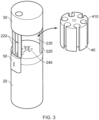
- Figure 3 shows the aerosol-generating device 1 of Figures 1 and 2 with the magazine 40 removed from the space 230.
- Figure 3 also more clearly shows how the support structure 220 connects the main body 20 with the heating unit portion 30.
- a projection in the form of an axial pin 240 is provided in the centre of the top surface of the main body 20.
- the axial pin 240 is engageable in a corresponding axial recess on the bottom surface of the magazine 40 so as to allow the magazine 40 to rotate about the longitudinal axis when correctly located in the space 230.
- the axial pin 240 may be retracted into the main body 20.
- the axial pin 240 may be re-engaged with the corresponding axial recess on the bottom surface of the magazine 40 (see Figure 4 ) when the magazine 40 is placed back into the space 230.
- the retraction and extension of the axial pin 240 could be controlled by a small electric motor in the main body 20, or by a manual slider or the like.
- the axial pin 240 may be provided with a spring to urge the axial pin 240 into the extended position except at times when the axial pin 240 is being actively retracted into the main body 20.
- the receptacles 410 of the magazine 40 can easily be loaded with consumables 80 when the magazine 40 has been displaced from the space 230.
- Figure 3 shows the magazine 40 being completely separated from the aerosol-generating device 1, it is also possible for the magazine 40 to be hingedly connected to the aerosol-generating device 1 so that the magazine 40 may be swung out of the space 230 about a hinge line that is parallel to the longitudinal axis. This enables easy access to the receptacles 410 of the magazine 40 for loading with fresh consumables 80 without the risk of misplacing the magazine 40.
- Figure 4 is similar to Figure 3 , and shows additional detail of the bottom surface 450 of the magazine 40 with the axial recess 460 that receives the axial pin 240 of the main body 20.
- the axial pin 240 engaged in the axial recess 460 enables low friction rotation of the magazine 40 about the longitudinal axis when correctly located in the space 230.
- a corresponding axial pin may be provided on the bottom surface of the heating unit portion 30 to engage with an axial recess 460 in the top surface 440 of the magazine 40.
- the magazine 40 may be provided with lock recesses 470 on the bottom surface 450 as shown, or on the top surface 440, or on both the bottom surface 450 and the top surface.
- the lock recesses 470 are arranged in a circle around the longitudinal axis, in this case around the axial recess 460.
- Each lock recess 470 is sized and shaped to receive a lock projection, for example a lock pin 250, that extends from the top surface 210 of the main body 20, or from the bottom surface of the heating unit portion 30, or from both the top surface 210 of the main body 20 and the bottom surface of the heating unit portion 30.
- the lock pin 250 (or lock pins 250) may be spring-loaded or magnetic.
- the lock pin 250 engages with a lock recess 470 when the magazine 40 is rotated to a position such that one of the receptacles 410 of the magazine 40 is correctly aligned with the receptacle 310 of the heating unit portion 30.
- the interaction between the lock pin 250 (or lock pins 250) and the lock recesses 470 creates a compression connection point that serves to resist rotation of the magazine 40 about the longitudinal axis when a receptacle 410 of the magazine 40 is correctly aligned with the receptacle of the heating unit 30.
- the resistance may be a gentle resistance, so as simply to give a tactile indication of correct alignment, or may be a locking resistance, so as to prevent rotation.
- the lock pin 250 (or lock pins 250) may be actively extendible from the aerosol-generating device 1 so as to engage with the lock recesses 470, and the lock pin 250 (or lock pins 250) may need to be retracted in order to permit further rotation of the magazine 40 about the longitudinal axis. It is important that the loading mechanism 50 is not operated when a receptacle 410 of the magazine 40 is not correctly aligned with the receptacle of the heating unit portion 30, otherwise the locking mechanism 50 may jam, or a consumable 80 may be damaged.
- the number of lock recesses 270 corresponds to the number of receptacles 410 of the magazine 40.
- the lock recesses 270 are distributed so that each locked position aligns a different receptacle 410 and consumable 80 contained with the receptacle 410 with the receptacle 310 of the heating unit portion 30, allowing the consumable 80 to be transferred from the receptacle 410 to the receptacle 310 by the loading mechanism 50.
- Each receptacle 410 of the magazine 40 is provided with an open longitudinal slot 420 at the circumferential surface of the magazine 40.
- the open longitudinal slot 420 is configured to receive a push member of the loading mechanism 50 so as to allow the push member to move up and down within the receptacle 410 and to transfer a consumable from the receptacle 410 to the receptacle 310.
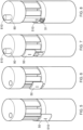
- Figures 5 to 7 show three stages of operation of the aerosol-generating device 1 of Figures 1 to 4 .
- the loading mechanism 50 is disengaged from the magazine 40, and the magazine 40 may be rotated about the longitudinal axis (subject to appropriate interaction between the lock pins 250 and lock recesses 470).
- a receptacle 410 of the magazine 40 containing a consumable 80 has been correctly aligned with the receptacle 310 of the heating unit portion 30, and the thumb slider of the loading mechanism 50 has been partially slid upwardly along the support structure 220.
- a push member of the loading mechanism 50 projects into the receptacle 410 through the open longitudinal slot 420 and pushes the consumable 80 from the receptacle 410 into the receptacle 310 in a direction parallel to the longitudinal axis.
- Figure 7 shows the thumb slider of the locking mechanism 50 in an uppermost position, having pushed the consumable 80 fully out of the receptacle 410 and into the receptacle 310. Then the consumable 80 is fully loaded, a mouthpiece end 810 of the consumable projects from the top surface of the heating unit portion 30.
- the magazine 40 cannot be rotated while the locking mechanism 50 is engaged through the open longitudinal slot 420.
- FIG 8 shows an aerosol-generating device 1 with an alternative loading mechanism 51.
- the loading mechanism 51 comprises a toothed wheel that engages with a toothed rack inside the aerosol-generating device 1 (as shown in more detail in Figure 21 ).
- Rotation of the toothed wheel by a user causes the toothed rack to move up or down in a direction parallel to the longitudinal axis.
- a push member projecting from the toothed rack can push a consumable 80 from the receptacle 410 into the receptacle 310.
- An indicator 510 such as a light emitting diode, can indicate when the consumable 80 is fully loaded into the receptacle 310 and when the heating unit in the heating unit portion 30 is activated to heat the consumable 80.
- Figure 9 shows a schematic vertical cross-section through an aerosol-generating device 1 similar to that shown on Figures 1 to 7 .
- the magazine 40 is omitted from Figure 9 for clarity.
- the heating unit portion 30 is shown supported by the support structure 220.
- the receptacle 310 of the heating unit portion 30 extends from the bottom surface of the heating unit portion 30 to the top surface of the heating portion 30.
- the receptacle 310 is a substantially cylindrical through-hole.
- An electromagnetic induction coil 320 is disposed around a circumference of the receptacle 310 in the heating unit portion 30.
- the induction coil 320 can be supplied with electrical power from a power source and control electronics in the main body 20 of the aerosol-generating device 1.
- Figure 9 shows how a fresh consumable 800 can be transferred from a receptacle 410 of a magazine 40 by pushing the consumable 800 upwardly into the receptacle 310 of the heating unit portion 30.
- Figure 9 shows a fresh consumable 800 in a location corresponding to a location of an aligned magazine receptacle 410, and a consumable 80 fully loaded into the heating unit receptacle 310, with an arrow showing the direction of transfer.
- the label 800 is used to denote the consumable 800 in the magazine receptacle 410, while the label 80 is used to denote the consumable 80 in the heating unit receptacle 310.
- the heating unit receptacle 310 is provided with a circumferential O-ring seal 350 at both the top end of the receptacle 310 and the bottom end of the receptacle 310.
- the O-ring seals 350 provide an airtight fit around the consumable 80 when fully loaded in the receptacle 310 by way of the loading mechanism 50.
- the consumable 80 is rod-shaped, and comprises a mouthpiece 810, and aerosol mixing portion 840, and an aerosol-generating substrate 850.
- the aerosol-generating substrate 850 is configured to generate an aerosol when heated.
- the aerosol-generating substrate 850 may be a sheet of crimped and gathered reconstituted tobacco cast leaf, but other aerosol-generating substates may be employed.
- a metallic susceptor 830 for example a strip of metal foil, is provided in or adjacent to the aerosol-generating substrate 850 in the consumable.
- the induction coil 320 When the induction coil 320 is powered, for example by an alternating current, a varying electromagnetic field is generated in the receptacle 310, and this induces an electric current in the metallic susceptor 830 to heat the metallic susceptor 830 and thus to heat the aerosol-generating substrate 850. As a result of this heating, an aerosol 100 is generated by the aerosol-generating substrate 850, and the aerosol 100 can be inhaled by a user through the mouthpiece 810 of the consumable 80.
- An electromagnetic shield 340 may be disposed outside a circumference of the induction coil 320 so as to confine or concentrate the electromagnetic field generated by the induction coil 320 to the volume of the receptacle 310. This may increase the efficiency of inductive heating.
- a thermal insulator 330 may be provided around the heating unit receptacle 310 so as to reduce heat loss in an outward direction. This may improve the efficiency of heating the aerosol-generating substrate 850 in the consumable 80.
- the thermal insulator 330 may also help to insulate parts of the heating unit portion 30 other than the receptacle 310 from the heat generated in the consumable 80. For example, this can help to keep the external surface of the heating unit portion 30 within safe temperatures, and can prevent heat damage being caused to electronic components in the heating unit portion 30.
- An air inlet 60 for example defined by a gap between the top surface 440 of the magazine 40 and a bottom surface of the heating unit portion 30, enabled entrainment of an air flow.
- a user inhales aerosol 100 from the mouthpiece 810 of the consumable 80, external air 90 is drawn into an end of the consumable 80 remote from the mouthpiece 810.
- the airflow passes through the consumable 80, across the aerosol-generating substrate 850, through the aerosol mixing portion 840 and through the mouthpiece 810 into a user's mouth when the user sucks on the mouthpiece 810.
- the O-ring seals 350 help to reduce or eliminate air leakage between the external circumference of the consumable 80 and the inner wall of the receptacle 310.
- the air inlet 60 may be configured with a one-way air valve, permitting airflow in only one direction (from outside to inside) through the air inlet 60. This can help to reduce moisture loss through evaporation from consumables 80 held in receptacles 410 of the magazine 40 when the magazine is loaded in the space 230 of the aerosol-generating device 1. It is generally desirable for the consumables 80 to be kept in a substantially airtight environment before use in order to maintain freshness.
- Consumables 80 held within receptacles 410 of the magazine 40 that are not aligned with the receptacle 310 of the heating unit portion 30 can be isolated from ambient air by way of the top surface of the main body 20 and the bottom surface of the heating unit portion 30 covering the respecting bottom and top ends of the receptacles 410. However, at least the top end of the receptacle 410 of the magazine 40 that is aligned with the receptacle 310 of the heating unit portion 30 may be exposed to ambient air unless further measures are taken, such as providing a one-way air valve in the air inlet 60. Additional or alternative features for isolating consumables 80 from ambient air will be described hereinbelow.
- the depleted consumable 80 needs to be removed from the receptacle 310 before a fresh consumable 80 can be inserted. This can be done in several ways.
- a depleted consumable 80 can automatically be pushed out of the heating unit receptacle 310, out of the top of the heating unit portion 30, by a fresh consumable 800 being pushed up into the heating unit receptacle 310 from an aligned magazine receptacle 410 by the loading mechanism 50.
- This may have the benefit of reducing the risk of a depleted consumable 80 being damaged or torn, which could happen if a user were simply to pull the mouthpiece end 810 of the depleted consumable 80 in order to remove the depleted consumable 80 from the heating unit receptacle 310.
- a depleted consumable 80 could be reinserted into an empty magazine receptacle 410 that is aligned with the heating unit receptacle 310 by operating the loading mechanism 50 in reverse, for example by pushing down the thumb slider or rotating the toothed wheel 51 in a reverse direction.
- the magazine 40 can be used for temporary storage of depleted consumables 80 as well as for storage of fresh consumables 800.
- the magazine receptacle 410 are substantially isolated from ambient air, this can help to reduce unwanted odours from depleted consumables 80 when the aerosol-generating device 1 is carried in a bag or pocket.
- a depleted consumable 80 could simply be pulled out of the heating unit receptacle 310 by way of a user grasping the exposed mouthpiece 810 of the depleted consumable 80 and pulling gently.
- the consumable 80, 800 may have a substantially circular cross-section, and the receptacles 310, 410 may have a corresponding substantially circular cross-section. Accordingly, the receptacles 310, 410 may take the form of substantially cylindrical tubes, and the consumables 80, 800 may have a corresponding substantially cylindrical shape so as to fit snugly, yet slidably, with the receptacles 310, 410.
- the consumables 80, 800 and the receptacles 310, 410 may have a substantially elliptical cross-section, or may have a substantially oval cross-section, or may have a polygonal cross-section, or may have any other appropriate cross-section, provided that the consumables 80, 800 fit snugly yet slidably in the receptacles 310, 410.
- FIG. 10 there is shown a consumable 800 and magazine 40 with a plurality of magazine receptacles 410 as hereinbefore described.
- Each magazine receptacle 410 has an open longitudinal slot 420 at a circumferential surface of the magazine 40.
- the magazine 40 has a top surface 440 and a bottom surface 470.
- Figure 11 shows the magazine 40 with a consumable 800 fully received in one of the magazine receptacles 410.
- the consumable 800 is snugly yet slidably held by the magazine receptacle.
- FIG. 12 shows the consumable 800 slid partially out of the magazine receptacle 410, with the mouthpiece 810 projecting from the top surface 440 of the magazine 40.
- the heating unit of the aerosol-generating device 1 may be configured for use with a variety of different types of consumables 80.
- different consumables 80 may contain different quantities or different concentrations of precursor materials in the aerosol-generating substrate.
- Different consumables 80 may be configured to release different quantities or different concentrations of nicotine or other active agents upon heating.
- Different consumables 80 may be configured with different flavour profiles, for example menthol flavour, or different types of tobacco flavour.
- the magazine 40 may be configured to allow selection of different types of consumables 80 by a user.
- the magazine 40 may be made of a transparent material or be provided with windows so as to allow a user to view the consumables 80 held within the magazine receptacles 410 and to select a particular consumable 80 for loading into the heating unit receptacle 310 for consumption.
- the aerosol-generating device 1 may be provided with a transparent wall portion around the space 230 so that the consumables 80 in the receptacles 410 of the magazine 40 can be viewed through the open longitudinal slits 420 and the transparent wall portion.
- the transparent wall portion may comprise a hinged door portion that can be opened so as to allow the magazine 40 to be loaded into and unloaded from the space 230.
- different types of consumable 80 may be distinguished from each other by way of distinguishing indicia, including text, colour or other markings.
- Different types of consumables 80 may require different heating profiles (such as temperature, rate of increase of temperature, total heating time etc.) for optimum enjoyment, and the heating unit portion 30 may be configured to apply different heating profiles. This may be automated by way of the heating unit portion 30 being provided with a sensor for reading indicia provided on the consumables 80 that identify the consumables 80 and allow a predetermined heating profile to be applied by the heating unit portion 30.
- the magazine 40 may be sold separately from the aerosol-generating device 1.
- the magazine 40 may be sold pre-loaded with consumables 80.
- a user may simply insert a new pre-loaded magazine 40 into the aerosol-generating device 1 when the user has run out of consumables 80.
- the old magazine 40 which may be empty or may contain used consumables 800 that have been transferred back into the receptacles 410 of the magazine 40 after use, may be returned to the retailer or manufacturer for recycling, together with the used consumables 800 where appropriate.
- Pre-loaded magazines 40 may be packaged in airtight packaging to help maintain freshness of the consumables 80.
- Figure 13 shows a schematic cross-section through the main body 20 of the aerosol-generating device 1, for example as shown in Figures 1 to 7 .
- the main body 20 may include a power supply and electronic components.
- the main body 20 of the illustrated embodiment may have a diameter of around 34.4mm, although it will be understood that this is by way of example only, and other dimensions may be preferred. Indeed, the dimensions given in the following description are provided primarily to give a sense of overall scale, and are not to be construed as limiting except where the context demands otherwise.
- Figure 14 shows a cross-section through a middle part of the aerosol-generating device 1 of Figure 1 , at the top surface 210 just below the magazine 40.
- the cross-section includes a re-entrant aperture 600 configured to receive a push member 610 of the loading mechanism 50.
- the re-entrant aperture 600 may have a diameter of about 7.1 mm.
- Also shown are the axial pin 240 and lock pins 250 (see Figures 3 and 4 ).
- Figure 15 shows a cross-section through the magazine 40, showing the magazine receptacles 410 and the open longitudinal slots 420.
- the magazine 40 may have a diameter of about 30.3mm.
- Each of the magazine receptacles 410 may have a diameter of about 7.1 mm.
- Figure 16 shows a cross-section through the heating unit portion 30, showing the heating unit receptacle 310.
- the heating unit receptacle 310 has a diameter of about 7.1mm, corresponding to the diameter of the magazine receptacles 410.
- the diameter of the heating unit portion 30 may be about 34.4mm to match the diameter of the main body portion 20.
- Figure 17 shows a cross-section through a bottom part of the magazine 40 held within the space 230.
- the space 230 is surrounded by a circumferential wall structure 260 comprising a fixed circumferential wall component 260a and a hinged circumferential door component 260b. Also shown are cross-sections of the struts 220a, 220b, 220c of the support structure 220.
- the fixed circumferential wall component 260a and the hinged circumferential door component 260b may be substantially transparent so as to allow the magazine 40 and the consumables 80 to be viewable from outside the aerosol-generating device 1.
- the hinged circumferential door component 260b may hinge outwardly about an edge of one of the struts 220b, 220c as shown in Figure 19 .
- the circumferential wall structure 260 covers all of the open longitudinal slots 420 of the receptacles 410 of the magazine 40 except for the receptacle 410 that is aligned with the receptacle 310 of the heating unit portion 30.
- the open longitudinal slot 420 of the aligned receptacle 410 will be open the outside of the aerosol-generating device 1 between the struts 220a, 220b.
- the thumb slider of the loading mechanism 50 may be moved upwardly on the outside of the aerosol-generating device 1, and this will cause the push member 500 to move upwardly inside the aligned magazine receptacle 410 in order to push a consumable 80 from the magazine 40 into the receptacle 310 of the heating unit portion 30.
- Figure 18 shows a cross-section through a middle part of the aerosol-generating device 1 and the magazine 40, showing the struts 220a, 220b, 220c of the support structure 220, the fixed circumferential wall component 260a and the hinged circumferential door component 260b of the circumferential wall structure 260.
- the hinged circumferential door component 260b subtends an angle of substantially 180 degrees from the central axis of the magazine 40 (i.e. the longitudinal axis).
- the hinged circumferential door component 260b subtends an angle of slightly less than 180 degrees. In this way, with the hinged circumferential door component 260b in an open position, the magazine 40 can be removed from the space 230 but will not fall out unexpectedly, even when the axial pin 240 and the locking pins 250 are retracted.
- FIG 19 shows an aerosol-generating device 1 similar to that shown in Figure 8 , but features described in relation to this embodiment may apply equally to the embodiments of Figures 1 to 7 and others.
- the aerosol-generating device 1 comprises a main body 20, a heating unit portion 30 and support structure 220.
- a magazine 40 with receptacles 410 each having an open longitudinal slot 420 is loaded into the space 230 of the aerosol-generating device 1 between the main body 20 and the heating unit portion 30.
- the space 230 and the magazine are surrounded by a circumferential wall structure 260 comprising a fixed circumferential wall component 260a and a hinged circumferential door component 260b.
- the circumferential wall structure 260 may be substantially transparent.
- the hinged circumferential door component 260b hinges about a strut of the support structure 220 so as to be moveable between an open position (shown in Figure 19 ), and a closed position. In the closed position, the hinged circumferential door component 260b, together with the fixed circumferential wall component 260a, defines a circumferential wall structure 260 that extends around the space 230 and isolates the receptacles 410 of the magazine 40 from ambient air.
- the loading mechanism 50 comprises a toothed wheel 51, and the magazine 40 need not be exposed to ambient air between struts of the support structure 220.
- the circumferential wall structure 260 helps to isolate consumables 800 held in the magazine receptacles 410 from ambient air. This can help to maintain freshness of the consumables 800.
- the circumferential wall structure 260 may be slidable along the direction of the longitudinal axis so as to allow the magazine 40 to be removed from or placed into the space 230.
- the circumferential wall structure 260, or at least a portion of the circumferential wall structure 260 may be retractable into or around the main body 20.
- Figure 20 shows a top view of the heating unit portion 30 of an embodiment.
- a cover 360 is provided to cover an exit aperture of the heating unit receptacle 310.
- the cover 360 may be pivotable between open and closed positions about a pivot 361.
- the cover 360 may be slidable between open and closed positions.
- the exit aperture of the heating unit receptacle 310 may be isolated from ambient air when there is no consumable 80 loaded into the receptacle 310 and when the aerosol-generating device 1 is not in active use. This can help to hinder ingress of air or egress of evaporated flavour components when the aerosol-generating device is not in use, and can help to maintain freshness of consumables 800 held within the receptacles 410 of the magazine 40.
- a cover 360 over the exit aperture of the heating unit receptacle 310 when the aerosol-generating device 1 is not in use can help to prevent fluff or debris from entering the receptacle 310 and causing blockages or interfering with the heating unit.
- a cover (not shown) may be provided at the entrance aperture (the bottom aperture) of the heating unit receptacle 310.
- the cover at the entrance aperture of the heating unit receptacle may also be movable between open and closed positions, for example by pivoting or sliding.
- the covers may be operatively linked so as to move together between open and closed positions.
- FIG 21 shows, in schematic form, how the loading mechanism 50 can be operatively linked with a moveable cover 360.
- the loading mechanism 50 comprises a toothed wheel 51.
- the toothed wheel 51 engages with a toothed rack 52, and rotation of the toothed wheel 51 causes the toothed rack 52 to move up (or down) in a direction parallel to the longitudinal axis.
- a push member 550 extends from the toothed rack 52. By moving the push member 550 upwardly when a magazine receptacle 410 is aligned with the heating unit receptacle 310, a consumable 800 held in the magazine receptacle 410 may be pushed into the heating unit receptacle 310 by the loading mechanism 50.
- rotation of the toothed wheel 51 may cause rotation of the pivot 361 by way of a suitable gearing mechanism (for example, a conical gear arrangement), and this can move the cover 360 of the exit aperture of the heating unit receptacle 310 from a closed position to an open position.
- a suitable gearing mechanism for example, a conical gear arrangement
- the toothed wheel 51 may be operated by hand, or may be driven by an electric motor.
- the loading mechanism 50 may be configured to activate the aerosol-generating device 1, for example by switching on powering to electronic components, when an element of the loading mechanism 50 id displaced from a switched-off position to a switched-on position.
- a light signal from a status LED 510 may indicate the user to further operate the loading mechanism 50, for example by further moving the thumb slider, so as to load a consumable 80 fully into the heating unit receptacle 310 so that the mouthpiece 810 is exposed at the top surface of the heating unit portion 30.
- the heating unit portion 30 may include a control mechanism configured automatically to initiate a heating process upon detection of the upper position of the loading mechanism 50, or upon detection of a consumable 80 fully inserted into the heating unit receptacle 310.
- the control mechanism could be an electronic controller linked to an electric motor that operates the loading mechanism 50, or could be a mechanical interface whereby two electrical contacts are brought together in the loading mechanism 50 when the consumable 80 is fully loaded into the heating unit receptacle 310.
- the detection of a consumable 80 fully loaded into the heating unit receptacle 310 could be achieved mechanically by having a pressure switch inside the heating unit receptacle 310, so that pressure switch is pressed when a consumable 80 is fully loaded into the heating unit receptacle 310.
- the pressure switch may activate the heating unit.
- the heating unit portion 30 may further comprise a metal sensor, for example an inductive sensor, so as to be able to distinguish between consumables 80 that comprise a metal susceptor (and are intended for inductive heating) and consumables 80 that do not comprise a metal susceptor (and are intended for non-inductive heating, for example resistive heating).
- the heating unit portion 30 may be configured only to be activatable when the correct type of consumable 80 is detected in the heating unit receptacle 310. This can help to prevent accidental use of the wrong type of consumable 80 if a user has a supply of different types of consumables 80 intended for different types of aerosol-generating device 1.
- the main body 20 of the aerosol-generating device 1 may comprise a housing made of one or more of metals, alloys and plastics, or composites of these materials.
- the heating unit portion 30 of the aerosol-generating device 1 may comprise a housing made of one or more of metals, alloys and plastics, or composites of these materials.
- the support structure 220 of the aerosol-generating device 1 may be made of one or more of metals, alloys and plastics, or composites of these materials.
- the magazine 40 of the aerosol-generating device 1 may be made of one or more of metals, alloys and plastics, or composites of these materials.
- the loading mechanism 50 of the aerosol-generating device 1 may be made of one or more of metals, alloys and plastics, or composites of these materials.
- the circumferential wall structure 260 of the aerosol-generating device 1 may be made of one or more of metals, alloys and plastics, or composites of these materials.
Landscapes
- Packaging Of Annular Or Rod-Shaped Articles, Wearing Apparel, Cassettes, Or The Like (AREA)
Abstract
There is disclosed a system comprising: an aerosol-generating device (1) comprising a receptacle (310) configured to receive a consumable (80), wherein the aerosol-generating device is configured to generate an aerosol from the consumable located at least partially in the receptacle; a magazine (40) comprising a plurality of receptacles (410) each configured to receive a consumable; and a loading mechanism (50) configured to transfer a consumable from a receptacle of the magazine to the receptacle of the aerosol-generating device.
Description
- The present disclosure relates to a system comprising an aerosol-generating device with a magazine for storing consumables and a loading mechanism for transferring a consumable from the magazine to the aerosol-generating device.
- Certain types of aerosol-generating devices use consumables in the form of rod-shaped aerosol-generating articles. Such aerosol-generating articles may comprise an aerosol-generating substrate that generates an aerosol when heated, one or more aerosol-cooling elements, and optionally a filter to prevent passage of debris from the aerosol-generating substrate. The aerosol-generating substrate may comprise a crimped and gathered sheet of tobacco cast leaf material, or any other substrate made of or impregnated with a substance that generates a desired aerosol upon application of heat.
- These types of aerosol-generating devices typically have a receptacle for receiving a rod-shaped consumable. Rod-shaped consumables are sold separately, often in packets of twenty rod-shaped consumables. When a user wants to consume a consumable, they must take a consumable from the packet and insert the consumable manually into the receptacle of the aerosol-generating device. A heating unit in the aerosol-generating device is activated to heat the consumable so as to generate an aerosol, and the user can then inhale the aerosol by sucking on an exposed end of the consumable that projects from the receptacle of the aerosol-generating device. After the consumable has been enjoyed, it is removed from the receptacle of the aerosol-generating device, and should be disposed of carefully so as not to pollute the environment.
- A user therefore needs to carry not just the aerosol-generating device, but also a supply of consumables, for example in the form of one or more packets of such consumables. Moreover, if no proper used consumable disposal facilities are available, the user may need temporarily to carry used consumables in the packet of unused consumables. Some used consumables may have an undesirable aroma that may be transferred to unused consumables in the packet.
- According to a first aspect of the present invention, there is provided a system comprising:
- an aerosol-generating device comprising a receptacle configured to receive a consumable, wherein the aerosol-generating device is configured to generate an aerosol from the consumable located at least partially in the receptacle;
- a magazine comprising a plurality of receptacles each configured to receive a consumable; and
- a loading mechanism configured to transfer a consumable from a receptacle of the magazine to the receptacle of the aerosol-generating device.
- Embodiments of the present invention allow a user to keep a plurality of fresh consumables in the magazine, one consumable in each receptacle of the plurality of receptacles of the magazine. When a user wishes to enjoy a consumable, they can operate the loading mechanism to transfer a fresh consumable from one of the plurality of receptacles of the magazine to the receptacle of the aerosol-generating device. When the fresh consumable has been loaded into the receptacle of the aerosol-generating device, aerosol-generating device can be activated to generate an aerosol for enjoyment by the user.
- Accordingly, embodiments of the present invention enable a plurality of fresh consumables to be carried integrally with the system, and the user may not need to carry a separate packet of fresh consumables.
- In some embodiments, a used consumable may be transferred from the receptacle of the aerosol-generating device back into an empty receptacle of the plurality of receptacles of the magazine. This provides a convenient storage of used consumables for later disposal in an environmentally friendly manner. Provided that the plurality of receptacles of the magazine are separated from each other, potential contamination of fresh consumables by used consumables can be avoided.
- Another advantage is that a user may load the plurality of receptacles of the magazine with different types of consumable, thereby providing a choice of consumable without the need to carry different packets of different types of consumables.
- The magazine may be rotatable about a longitudinal axis so as to enable receptacles of the magazine to be individually aligned with the receptacle of the aerosol-generating device. In this way, a magazine may be loaded with consumables, for example one consumable in each receptacle, and the magazine may be rotated about the longitudinal axis so that a receptacle of the magazine is aligned with the receptacle of the chamber, permitting the consumable to be transferred longitudinally from the receptacle of the magazine to the receptacle of the chamber.
- The loading mechanism may be configured to transfer a consumable from the receptacle of the magazine to the receptacle of the aerosol-generating device when the receptacle of the magazine is aligned with the receptacle of the aerosol-generating device.
- The loading mechanism may be a manually operated mechanism. For example, the loading mechanism may comprise a sliding mechanism with a member on the outside of the aerosol-generating device that can be reciprocated in the direction of the longitudinal axis by a user's thumb or finger, and a member that extends into the receptacle of the magazine and is moveable with the external member to push the consumable from the receptacle of the magazine to the receptacle of the aerosol-generating device when the receptacle of the magazine is aligned with the receptacle of the aerosol-generating device. The loading mechanism may comprise a rack and pinion mechanism with a toothed thumbwheel accessible from the outside of the aerosol-generating device that can be rotated to move a toothed rack in the direction of the longitudinal axis, and a member that extends into the receptacle of the magazine and is moveable with the toothed rack to push the consumable from the receptacle of the magazine to the receptacle of the aerosol-generating device when the receptacle of the magazine is aligned with the receptacle of the aerosol-generating device
- The loading mechanism may be a motorised mechanism. For example, the loading mechanism may comprise an electric motor configured to move a member that extends into the receptacle of the magazine to push the consumable from the receptacle of the magazine to the receptacle of the aerosol-generating device when the receptacle of the magazine is aligned with the receptacle of the aerosol-generating device. The electric motor may be activated by a switch on the aerosol-generating device, for example a button that can be pressed by a user. There may be provided circuitry that only allows the electric motor to be activated when the when the receptacle of the magazine containing the consumable is aligned with the receptacle of the aerosol-generating device. For example, the circuitry may comprise electrical contacts on the aerosol-generating device and electrical contacts on the magazine that only contact each other when the receptacle of the magazine containing the consumable is aligned with the receptacle of the aerosol-generating device. This can help to prevent activation of the electric motor when the magazine is not properly rotationally aligned with the aerosol-generating device, and can thus help to prevent jamming.
- The magazine may be displaceable relative to the aerosol-generating device so as to allow consumables to be filled into or removed from the receptacles of the magazine. For example, the magazine may be displaced from the aerosol-generating device in a direction substantially perpendicular to the longitudinal axis. The magazine may be entirely removable from the aerosol-generating device. The magazine may be displaceable by a predetermined amount but prevented from being displaced beyond this amount by way of a stopping mechanism.
- The magazine may be hingedly connected to the aerosol-generating device. The magazine may be hingedly connected to the aerosol-generating device about an axis that is substantially parallel to the longitudinal axis. The hinged connection may be located at or close to a circumferential edge of the magazine.
- The system may further comprise an aerosol-generating unit for generating aerosol from the consumable(s). The aerosol-generating unit may be a heating unit configured to heat the consumable so as to generate the aerosol. The heating unit may be provided in the aerosol-generating device. The heating unit may be provided in the consumable. The aerosol-generating device may comprise at least one component of the heating unit while the consumable comprises at least one other component of the heating unit. The heating unit may be activatable by a user. The heating unit may be activated by a switch on the aerosol-generating device, for example a button that can be pressed by a user.
- For example, the heating unit may be an inductive heating unit. An induction coil connectable to a power supply may be provided in the aerosol-generating device. The induction coil may be disposed adjacent to or surrounding the receptacle of the aerosol-generating device. The consumable may comprise a susceptor, for example a metal element, which is configured to be heated when exposed to an alternating electromagnetic field by the induction coil.
- The heating unit may be a resistive heating unit. An electrically resistive element connectable to a power supply may be provided in the aerosol-generating device. The electrically resistive element may be disposed adjacent to or surrounding the receptacle of the aerosol-generating device. The electrically resistive element may be configured to penetrate the consumable when the consumable is in the receptacle of the aerosol-generating device. The electrically resistive element may be configured to contact the consumable when the consumable is in the receptacle of the aerosol-generating device.
- In other examples, the heating unit may be a microwave heating unit, or a dielectric heating unit.
- Alternatively, the aerosol-generating device may generate an aerosol by subjecting the consumable to ultrasonic vibrations. For example, the aerosol-generating device may comprise an ultrasonic transducer connectable to a power supply and configured to direct ultrasonic vibrations at or to the consumable when the consumable is in the receptacle of the aerosol-generating device. The ultrasonic transducer may be activated by a switch on the aerosol-generating device, for example a button that can be pressed by a user.
- The receptacle of the aerosol-generating device may comprise a chamber having a first open end to receive a consumable from an aperture of the magazine, and a second open end from which a mouthpiece end of the consumable projects when the consumable is fully loaded into the receptacle of the aerosol-generating device. The chamber may be substantially cylindrical.
- The loading mechanism may be further configured to eject a used consumable from the receptacle of the aerosol-generating device, through the second open end of the chamber, when a fresh consumable is transferred from a receptacle of the magazine to the receptable of the aerosol-generating device through the first open end of the chamber. The fresh consumable may in effect be used to push the used consumable out through the second open end of the chamber, and the user can then dispose of the used consumable in a responsible manner.
- The first open end of the chamber may be provided with a substantially airtight cover that is moveable between an open position, allowing communication with a receptacle of the magazine so as to allow a consumable to be loaded into the chamber, and a closed position, sealing the first open end of the chamber. When the substantially airtight cover is in the closed position, the receptacles of the magazine may be isolated from external atmosphere. This can help to keep unused consumables in the receptacles of the magazine fresh.
- The second open end of the chamber may be provided with a substantially airtight cover that is moveable between an open position, allowing the mouthpiece end of the consumable loaded into the chamber to project from the aerosol-generating device, and a closed position, sealing the second open end of the chamber when no consumable is loaded into the chamber. This can help to prevent ingress of air into the receptacle of the aerosol-generating device and thence into the receptacles of the magazine when the aerosol-generating device is not being used for generating an aerosol. This can help to keep unused consumables in the receptacles of the magazine fresh.
- The loading mechanism may be further configured to transfer a consumable from the receptacle of the aerosol-generating device to a receptacle of the magazine. In these embodiments, a used consumable may be transferred from the receptacle of the aerosol-generating device back into an empty receptacle of the magazine for temporary storage until the magazine can be conveniently emptied of used consumables and the used consumables disposed of in a responsible manner.
- The receptacles of the magazine may be substantially sealed from external atmosphere when not aligned with the receptacle of the aerosol-generating device and when the magazine is not displaced from the aerosol-generating device for loading with consumables. This can help to keep unused consumables in the receptacles of the magazine fresh.
- The receptacles of the magazine may be substantially sealed from external atmosphere by a cover that is moveable between open and closed positions.
- An end of the receptacle of the aerosol-generating device closest to the magazine may be provided with an air inlet to allow air to be drawn through a consumable received in the receptacle of the aerosol-generating device. The air inlet may comprise a one-way valve. In this way, air flow through the consumable may be controlled, with air only passing through the consumable when a user draws on a mouthpiece end of the consumable. Provision of a one-way valve may further help to reduce exposure of unused consumables in receptacles of the magazine to air, thus helping to keep the unused consumables fresh.
- The receptacles of the magazine may be transparent or may comprise windows to allow consumables held within the receptacles of the magazine to be viewed from outside the magazine. This allows a user to determine how many unused consumables are available in the magazine, and whether or not the magazine might need to be refilled. In addition, a user may load the magazine with an assortment of different consumables (for example of different strengths or flavours), and the user can then easily select a desired consumable for enjoyment by aligning the receptacle of the magazine containing the desired consumable with the receptacle of the aerosol-generating device and activating the loading mechanism. Different types of consumables may be provided with distinguishing indicia, for example different colours or markings, in order to facilitate selection.
- The loading mechanism may be operatively connected to the heating unit so as to activate the heating unit when a consumable is fully loaded into the receptacle of the aerosol-generating device. The loading mechanism may be operatively connected to the ultrasonic transducer so as to activate the ultrasonic transducer when a consumable is fully loaded into the receptacle of the of aerosol-generating device. In this way, the aerosol-generating device may automatically start to generate an aerosol from the consumable when the consumable is fully loaded into the receptacle of the aerosol-generating device. The heating unit or the ultrasonic transducer may automatically switch off again after a predetermined period of time.
- According to a second aspect of the present invention, there is provided a magazine for use with an aerosol-generating device comprising a cavity configured to receive and retain the magazine at least partially within the aerosol-generating device;
wherein the magazine comprises a plurality of receptacles each holding or configured to receive a consumable to be loaded into the aerosol-generating device. - The aerosol-generating device may comprise a receptacle configured to receive a consumable from the magazine, and the aerosol-generating device may be configured to generate an aerosol from the consumable located at least partially in the receptacle.
- The magazine may be rotatable about a longitudinal axis. The longitudinal axis of the magazine may be aligned with a longitudinal axis of the aerosol-generating device when the magazine is coupled with the aerosol-generating device. The longitudinal axis may be a substantially central longitudinal axis of rotation. The longitudinal axis may be an axis of substantial rotational symmetry. The magazine may be configured to be engageable with the aerosol-generating device in such a way that the magazine is rotatable about the longitudinal axis when engaged with the aerosol-generating device.
- The magazine may be rotatable about a longitudinal axis so as to align the receptacles of the magazine individually with the receptacle of the aerosol-generating device such that a consumable within the aligned receptacle of the magazine can be transferred from the aligned receptacle of the magazine to the receptacle of the aerosol-generating device by a loading mechanism.
- The receptacles of the magazine may comprise a plurality of chambers arranged substantially parallel to the longitudinal axis. Each one of the chambers may be at least partially cylindrical.
- The receptacles of the magazine may be arranged in a circle around the longitudinal axis and substantially parallel to the longitudinal axis and to each other.
- The magazine may comprise a drum-shaped body with the receptacles disposed adjacent to a circumferential surface of the drum-shaped body.
- The receptacles may each comprise an open longitudinal slot at the circumferential surface of the drum-shaped body. The open longitudinal slot permits a member of a loading mechanism provided in the aerosol-generating device to extend into the receptacle of the magazine and to push a consumable out of the receptacle of the magazine and into an aligned receptacle of the aerosol-generating device.
- The magazine may comprise a top surface substantially perpendicular to the longitudinal axis and a bottom surface substantially perpendicular to the longitudinal axis. The magazine may be substantially drum-shaped.
- Either the top surface or the bottom surface or both of the top surface and the bottom surface may be provided with a central projection or indentation to releasably engage with corresponding indentations or projections on the aerosol-generating device. This facilitates rotation of the magazine about the longitudinal axis when engaged with the aerosol-generating device while helping to prevent the magazine from becoming inadvertently disengaged from the aerosol-generating device. Additional projections, indentations, or projections and indentations may be provided in a substantially circular arrangement about the longitudinal axis on the top surface or the bottom surface or both the top surface and the bottom surface. These additional projections, indentations, or projections and indentations may be positioned to engage with corresponding features on the aerosol-generating device whenever a receptacle of the magazine is correctly aligned with the receptacle of the aerosol-generating device. This can provide a haptic indication to a user when a receptacle of the magazine is correctly aligned with the receptacle of the aerosol-generating device so as to allow a consumable to be transferred from the receptacle of the magazine to the receptacle of the aerosol-generating device.
- The magazine may be made of a substantially transparent material. For example, the magazine may be made of a substantially transparent plastics material.
- The magazine may be provided (or sold) separately from the aerosol-generating device. The magazine may be provided (or sold) pre-loaded with consumables. In this way, instead of buying a conventional cardboard packet of consumables and loading the consumables into the magazine by hand, a user may simply insert a new pre-loaded magazine into the aerosol-generating device when the user has run out of consumables. The old magazine, which may be empty or may contain used consumables that have been transferred back into the receptacles of the magazine after use, may be returned to the retailer or manufacturer for recycling, together with the used consumables where appropriate. Pre-loaded magazines may be packaged in airtight packaging. In embodiments where the receptacles of the magazine are isolated from ambient air when the magazine is loaded into the aerosol-generating device, exposure of consumables to atmosphere can be much reduced. This can help to maintain freshness of the consumables.
- According to a third aspect of the present invention, there is provided a loading mechanism for loading consumables into a receptacle of an aerosol-generating device from one of a plurality of receptacles of a magazine each configured to receive a consumable, wherein the loading mechanism comprises a member operable to push a consumable from one of the plurality of receptacles of the magazine into the receptacle of the aerosol-generating device when the one of the plurality of receptacles is longitudinally aligned with the receptacle of the aerosol-generating device by rotating the magazine relative to the aerosol-generating device.
- The loading mechanism may comprise a portion that is located on an exterior portion of the aerosol-generating device, the portion being connected to the member, and the portion being configured to be manually displaced in a direction substantially parallel to a longitudinal axis of the one of the plurality of receptacles of the magazine so that the member is also displaced along the one of the plurality of receptacles of the magazine. The portion on the exterior portion of the aerosol-generating device may be a slider operable by a user's thumb or finger. The portion may comprise a toothed wheel that is rotatable, for example by way of a user's thumb, so as to displace a toothed rack in the direction substantially parallel to the longitudinal direction. The toothed rack may be contained within a body of the aerosol-generating device.
- The loading mechanism may comprise a motor, the motor being operable to displace the member, and the member being configured to be displaced by the motor in a direction along a longitudinal axis of the one of the plurality of receptacles of the magazine. The motor may be an electric motor. The electric motor may be activated by a switch on the aerosol-generating device, for example a button that can be pressed by a user. There may be provided circuitry that only allows the electric motor to be activated when the when the receptacle of the magazine containing the consumable is aligned with the receptacle of the aerosol-generating device. For example, the circuitry may comprise electrical contacts on the aerosol-generating device and electrical contacts on the magazine that only contact each other when the receptacle of the magazine containing the consumable is aligned with the receptacle of the aerosol-generating device. This can help to prevent activation of the electric motor when the magazine is not properly rotationally aligned with the aerosol-generating device, and can thus help to prevent jamming.
- The loading mechanism may comprise a gearing mechanism configured to move a substantially airtight cover at one or other or both ends of the receptacle of the aerosol-generating device between closed and open positions so as to allow the consumable to be pushed from the one of the receptacles of the magazine into the receptacle of the aerosol-generating device. When the substantially airtight cover is in the closed position, the receptacles of the magazine may be isolated from external atmosphere. This can help to keep unused consumables in the receptacles of the magazine fresh.
- The magazine may comprise a drum-shaped body with the receptacles of the magazine disposed adjacent to a circumferential surface of the drum-shaped body, wherein the receptacles of the magazine each comprise an open longitudinal slot at the circumferential surface of the drum-shaped body, and wherein the member is configured to project through the open longitudinal slot of one of the receptacles of the magazine when the consumable is pushed from the one of the receptacles of the magazine into the receptacle of the aerosol-generating device.
- According to a fourth aspect of the present invention, there is provided a method of loading a consumable into a receptacle of an aerosol-generating device, wherein a magazine comprising a plurality of receptacles each containing a consumable is displaceably connected to the aerosol-generating device, the magazine is displaced relative to the aerosol-generating device so as longitudinally to align one of the plurality of receptacles of the magazine with the receptacle of the aerosol-generating device, and wherein a loading mechanism is operated to push a consumable from aligned receptacle of the magazine to the receptacle of the aerosol-generating device.
- The magazine may be rotatably displaceable relative to the aerosol-generating device. The magazine may be rotatable displaceable relative to the aerosol-generating device in the manner hereinbefore described.
- The loading mechanism may be manually operated. The loading mechanism may be operated by a user moving a slider on an outside of the aerosol-generating device with a thumb or finger. The loading mechanism may be operated by a user rotating a toothed wheel projecting at an outside of the aerosol-generating device with a thumb or finger.
- The loading mechanism may comprise a member that projects into the aligned one of the plurality of receptacles of the magazine and an external slider connected to the member, and the external slider may be manually moved in a direction parallel to a longitudinal axis of the aligned one of the plurality of receptacles of the magazine so as to cause the member to push the consumable from the aligned one of the plurality of receptacles of the magazine into the receptacle of the aerosol-generating device.
- The loading mechanism may be operated by a user rotating a toothed wheel projecting at an outside of the aerosol-generating device with a thumb or finger. The loading mechanism may comprise a member that projects into the aligned one of the plurality of receptacles of the magazine and a toothed rack that is engaged by the toothed wheel, and the toothed wheel may be manually rotated so as to move the toothed rack in a direction parallel to a longitudinal axis of the aligned one of the plurality of receptacles of the magazine so as to cause the member to push the consumable from the aligned one of the plurality of receptacles of the magazine into the receptacle of the aerosol-generating device.
- The loading mechanism may be driven by a motor. The motor may be an electric motor.
- The loading mechanism may comprise a member that projects into the aligned one of the plurality of receptacles of the magazine, and the member may be driven by the motor in a direction parallel to a longitudinal axis of the aligned one of the plurality of receptacles of the magazine so as to cause the member to push the consumable from the aligned one of the plurality of receptacles of the magazine into the receptacle of the aerosol-generating device.
- The loading mechanism may comprise a gearing mechanism and the gearing mechanism may move a substantially airtight cover at one or other or both ends of the receptacle of the aerosol-generating device between closed and open positions so as to allow the consumable to be pushed from the one of the receptacles of the magazine into the receptacle of the aerosol-generating device.
- The magazine may be hingedly connected to the aerosol-generating device and moveable between an engaged position in which all of the receptacles of the magazine are covered by the aerosol-generating device and a loading position in which the receptacles of the magazine are exposed, and wherein consumables are loaded into the magazine when the magazine is in the loading position.
- The aerosol-generating device may comprise a heating unit operable to heat the consumable when loaded into the receptacle of the aerosol-generating device.
- The heating unit may be activated by the loading mechanism when the consumable is pushed into the receptacle of the aerosol-generating device.
- The aerosol-generating device may comprise an ultrasonic transducer operable to direct ultrasonic vibrations to or at the consumable when loaded into the receptacle of the aerosol-generating device.
- The ultrasonic transducer may be activated by the loading mechanism when the consumable is pushed into the receptacle of the aerosol-generating device.
- A consumable may be transferred from the receptacle of the aerosol-generating device into an empty aligned one of the receptacles of the magazine after the consumable has been used. This allows used consumables to be stored temporarily in receptacles of the magazine until such time that the used consumables can be disposed of responsibly.
- A consumable may be ejected from the receptacle of the aerosol-generating device after the consumable has been used. The consumable may then be disposed of responsibly.
- As used herein, the term "aerosol-generating device" refers to a device configured to generate an aerosol from an aerosol-generating substrate. The aerosol-generating substrate may be a solid, a liquid, a gel or a powder. Aerosol may be generated by vaporisation from the aerosol-generating substrate. Vaporisation may be achieved by heating the aerosol-generating substrate, or by subjecting the aerosol-generating substrate to ultrasonic vibration.
- As used herein, the term "component" is used to describe an element of a larger whole. For example, component is used to describe a part of an aerosol-generating article. Component may also refer to more than one part of an aerosol-generating article.
- As used herein, the term "consumable" refers to an article comprising an aerosol-generating substrate that is configured to be used with an aerosol-generating device. The aerosol-generating substrate may comprise a nicotine-containing substance, e.g. tobacco. The article may comprise additional components such as a mouthpiece, an aerosol mixing portion, a filter portion, a flavour portion and so forth. A consumable preferably has a rod-like or cylindrical form factor. A consumable preferably has a constant cross-section along its length, which may be circular, elliptical or oval, but could also have other shapes, including polygonal.
- As used herein, the term "controller" refers to an electronic component or components configured to receive and process electronic signals. The controller may be a microprocessor or a microcontroller. The controller may be configured as one or more integrated circuits.
- As used herein, the term "loading mechanism" refers to one or more members that are operable to move a consumable from a receptacle of a magazine to a receptacle of the aerosol-generating device, or vice versa. A loading mechanism may be manually operated or motor-driven or a combination of manually operated and motor-driven.
- As used herein, the term "magazine" refers to a component comprising a plurality of receptacles each configured to receive a consumable.
- As used herein, the term "predetermined" is used to describe a parameter that is established in advance.
- As used herein, the term "receptacle" refers to a chamber within a larger component that is sized and shaped snugly to receive a consumable but to allow the consumable to slide through the chamber in a longitudinal direction. A receptacle may be substantially cylindrical, and preferably has a constant cross-section along its length, which may be circular, elliptical or oval, but could also have other shapes, including polygonal.
- As used herein, the term "substantially airtight" refers to an arrangement of two or more components that prevents free passage of air between the components. Although the term "substantially airtight" encompasses hermetic seals, it also extends to arrangements that might not prevent passage of pressurised air, but do hinder passage of air at ambient pressures, at least to the extent of reducing moisture loss due to evaporation.
- The invention is defined in the claims. However, below there is provided a non-exhaustive list of non-limiting examples. Any one or more of the features of these examples may be combined with any one or more features of another example, embodiment, or aspect described herein.
- Example Ex1: A system comprising:
- an aerosol-generating device comprising a receptacle configured to receive a consumable, wherein the aerosol-generating device is configured to generate an aerosol from the consumable located at least partially in the receptacle;
- a magazine comprising a plurality of receptacles each configured to receive a consumable; and
- a loading mechanism configured to transfer a consumable from a receptacle of the magazine to the receptacle of the aerosol-generating device.
- Example Ex2: The system according to Example Ex1, wherein the magazine is rotatable about a longitudinal axis so as to enable receptacles of the magazine to be individually aligned with the receptacle of the aerosol-generating device.
- Example Ex3: The system according to Example Ex2, wherein the loading mechanism is configured to transfer a consumable from the receptacle of the magazine to the receptacle of the aerosol-generating device when the receptacle of the magazine is aligned with the receptacle of the aerosol-generating device.
- Example Ex4: The system according to any preceding Example, wherein the loading mechanism is a manually-operated mechanism.
- Example Ex5: The system according to any one of Examples Ex1 to Ex3, wherein the loading mechanism is a motorised mechanism.
- Example Ex6: The system according to any preceding Example, wherein the magazine is displaceable relative to the aerosol-generating device so as to allow consumables to be filled into or removed from the receptacles of the magazine.
- Example Ex7: The system according to Example Ex6, wherein the magazine is hingedly connected to the aerosol-generating device.
- Example Ex8: The system according to any preceding Example, further comprising a heating unit configured to heat the consumable so as to generate the aerosol,
wherein preferably the aerosol-generating device comprises the heating unit, the consumable comprises the heating unit, or the aerosol-generating device comprises at least one component of the heating unit while the consumable comprises at least one other component of the heating unit. - Example Ex9: The system according to Example Ex8, wherein the heating unit is an inductive heating unit.
- Example Ex10: The system according to Example Ex8, wherein the heating unit is a resistive heating unit.
- Example Ex11: The system according to any preceding Example, wherein the receptacle of the aerosol-generating device comprises a chamber having a first open end to receive a consumable from an aperture of the magazine, and a second open end from which a mouthpiece end of the consumable projects when the consumable is fully loaded into the receptacle of the aerosol-generating device, optionally wherein the chamber is cylindrical.
- Example Ex12: The system according to Example Ex11, wherein the loading mechanism is further configured to eject a used consumable from the receptacle of the aerosol-generating device, through the second open end of the chamber, when a fresh consumable is transferred from a receptacle of the magazine to the receptable of the aerosol-generating device through the first open end of the chamber.
- Example Ex13: The system according to Example Ex11 or Ex12, wherein the first open end of the chamber is provided with a substantially airtight cover that is moveable between an open position, allowing communication with a receptacle of the magazine so as to allow a consumable to be loaded into the chamber, and a closed position, sealing the first open end of the chamber.
- Example Ex14: The system according to any one of Examples Ex11 to Ex13, wherein the second open end of the chamber is provided with a substantially airtight cover that is moveable between an open position, allowing the mouthpiece end of the consumable loaded into the chamber to project from the aerosol-generating device, and a closed position, sealing the second open end of the chamber when no consumable is loaded into the chamber.
- Example Ex15: The system according to any preceding Example, wherein the loading mechanism is further configured to transfer a consumable from the receptacle of the aerosol-generating device to a receptacle of the magazine.
- Example Ex16: The system according to any preceding Example, wherein the receptacles of the magazine are substantially sealed from external atmosphere when not aligned with the receptacle of the aerosol-generating device and when the magazine is not displaced from the aerosol-generating device for loading with consumables.
- Example Ex17: The system according to Example Ex16, wherein the receptacles of the magazine are substantially sealed from external atmosphere by a cover that is moveable between open and closed positions.
- Example Ex18: The system according to any preceding Example, wherein an end of the receptacle of the aerosol-generating device closest to the magazine is provided with an air inlet to allow air to be drawn through a consumable received in the receptacle of the aerosol-generating device.
- Example Ex19: The system according to Example Ex18, wherein the air inlet comprises a one-way valve.
- Example Ex20: The system according to any preceding Example, wherein the receptacles of the magazine are transparent or comprise windows to allow consumables held within the receptacles of the magazine to be viewed from outside the magazine.
- Example Ex21: The system according to Example Ex8 or any one of Examples Ex9 to Ex20 depending from Example Ex8, wherein the loading mechanism is operatively connected to the heating unit so as to activate the heating unit when a consumable is fully loaded into the receptacle of the aerosol-generating device.
- Example Ex22: The system according to any preceding Example, further comprising one or more consumables for use with the system.
- Example Ex23: A magazine for use with an aerosol-generating device comprising a cavity configured to receive and retain the magazine at least partially within the aerosol-generating device;
wherein the magazine comprises a plurality of receptacles each holding or configured to receive a consumable to be loaded into the aerosol-generating device. - Example Ex24: The magazine according to Example Ex23, wherein the aerosol-generating device comprises a receptacle configured to receive a consumable from the magazine, and wherein the aerosol-generating device is configured to generate an aerosol from the consumable located at least partially in the receptacle.
- Example Ex25: The magazine according to Example Ex23 or Ex24, wherein the magazine is rotatable about a longitudinal axis.
- Example Ex26: The magazine according to Example Ex23 or Ex24, wherein the magazine is rotatable about a longitudinal axis so as to align the receptacles of the magazine individually with the receptacle of the aerosol-generating device such that a consumable within the aligned receptacle of the magazine can be transferred from the aligned receptacle of the magazine to the receptacle of the aerosol-generating device by a loading mechanism.
- Example Ex27: The magazine according to any one of Examples Ex23 to Ex26, wherein the receptacles of the magazine comprise a plurality of chambers arranged substantially parallel to the longitudinal axis, wherein preferably each one of the chambers is at least partially cylindrical.
- Example Ex28: The magazine according to any one of Examples Ex23 to Ex27, wherein the receptacles of the magazine are arranged in a circle around the longitudinal axis and substantially parallel to the longitudinal axis and to each other.
- Example Ex29: The magazine according to any one of Examples Ex23 to Ex28, wherein the magazine comprises a drum-shaped body with the receptacles disposed adjacent to a circumferential surface of the drum-shaped body.
- Example Ex30: The magazine according to Example Ex29, wherein the receptacles each comprise an open longitudinal slot at the circumferential surface of the drum-shaped body.
- Example Ex31: The magazine according to any one of Examples Ex23 to Ex30, wherein the magazine comprises a top surface substantially perpendicular to the longitudinal axis and a bottom surface substantially perpendicular to the longitudinal axis.
- Example Ex32: The magazine according to Example Ex31, wherein either the top surface or the bottom surface or both of the top surface and the bottom surface is provided with a central projection or indentation to releasably engage with corresponding indentations or projections on the aerosol-generating device.
- Example Ex33: The magazine according to any one of Examples Ex23 to Ex32, wherein the magazine is made of a substantially transparent material.
- Example Ex34: The magazine according to any one of Examples Ex23 to Ex33, further comprising a consumable loaded into each receptacle.
- Example Ex35: The magazine according to Example Ex34, contained within substantially airtight packaging configured to be removed by a user before loading the magazine into the cavity of the aerosol-generating device.
- Example Ex36: A loading mechanism for loading consumables into a receptacle of an aerosol-generating device from one of a plurality of receptacles of a magazine each configured to receive a consumable, wherein the loading mechanism comprises a member operable to push a consumable from one of the plurality of receptacles of the magazine into the receptacle of the aerosol-generating device when the one of the plurality of receptacles is longitudinally aligned with the receptacle of the aerosol-generating device by rotating the magazine relative to the aerosol-generating device.
- Example Ex37: The loading mechanism according to Example Ex36, wherein the loading mechanism comprises a portion that is located on an exterior portion of the aerosol-generating device, the portion being connected to the member, and the portion being configured to be manually displaced in a direction substantially parallel to a longitudinal axis of the one of the plurality of receptacles of the magazine so that the member is also displaced along the one of the plurality of receptacles of the magazine.
- Example Ex38: The loading mechanism according to Example Ex36, wherein the loading mechanism comprises a motor, the motor being operable to displace the member, and the member being configured to be displaced by the motor in a direction along a longitudinal axis of the one of the plurality of receptacles of the magazine.
- Example Ex39: The loading mechanism according to any one of Examples Ex36 to Ex38, wherein the loading mechanism comprises a gearing mechanism configured to move a substantially airtight cover at one or other or both ends of the receptacle of the aerosol-generating device between closed and open positions so as to allow the consumable to be pushed from the one of the receptacles of the magazine into the receptacle of the aerosol-generating device.
- Example Ex40: The loading mechanism according to any one of Examples Ex36 to Ex39, wherein the magazine comprises a drum-shaped body with the receptacles of the magazine disposed adjacent to a circumferential surface of the drum-shaped body, wherein the receptacles of the magazine each comprise an open longitudinal slot at the circumferential surface of the drum-shaped body, and wherein the member is configured to project through the open longitudinal slot of one of the receptacles of the magazine when the consumable is pushed from the one of the receptacles of the magazine into the receptacle of the aerosol-generating device.
- Example Ex41: A method of loading a consumable into a receptacle of an aerosol-generating device, wherein a magazine comprising a plurality of receptacles each containing a consumable is displaceably connected to the aerosol-generating device, the magazine is displaced relative to the aerosol-generating device so as longitudinally to align one of the plurality of receptacles of the magazine with the receptacle of the aerosol-generating device, and wherein a loading mechanism is operated to push a consumable from aligned receptacle of the magazine to the receptacle of the aerosol-generating device.
- Example Ex42: The method according to Example Ex41, wherein the magazine is rotatably displaceable relative to the aerosol-generating device.
- Example Ex43: The method according to Example Ex41 or Ex42, wherein the loading mechanism is manually operated.
- Example Ex44: The method according to Example Ex43, wherein the loading mechanism comprises a member that projects into the aligned one of the plurality of receptacles of the magazine and an external slider connected to the member, wherein the external slider is manually moved in a direction parallel to a longitudinal axis of the aligned one of the plurality of receptacles of the magazine so as to cause the member to push the consumable from the aligned one of the plurality of receptacles of the magazine into the receptacle of the aerosol-generating device.
- Example Ex45: The method according to Example Ex41 or Ex42, wherein the loading mechanism is driven by a motor.
- Example Ex46: The method according to Example Ex45, wherein the loading mechanism comprises a member that projects into the aligned one of the plurality of receptacles of the magazine, wherein the member is driven by the motor in a direction parallel to a longitudinal axis of the aligned one of the plurality of receptacles of the magazine so as to cause the member to push the consumable from the aligned one of the plurality of receptacles of the magazine into the receptacle of the aerosol-generating device.
- Example Ex47: The method according to any one of Examples Ex41 to Ex46, wherein the loading mechanism comprises a gearing mechanism and wherein the gearing mechanism moves a substantially airtight cover at one or other or both ends of the receptacle of the aerosol-generating device between closed and open positions so as to allow the consumable to be pushed from the one of the receptacles of the magazine into the receptacle of the aerosol-generating device.
- Example Ex48: The method according to any one of Examples Ex41 to Ex47, wherein the magazine is hingedly connected to the aerosol-generating device and moveable between an engaged position in which all of the receptacles of the magazine are covered by the aerosol-generating device and a loading position in which the receptacles of the magazine are exposed, and wherein consumables are loaded into the magazine when the magazine is in the loading position.
- Example Ex49: The method according to any one of Examples Ex41 to Ex48, wherein the aerosol-generating device comprises a heating unit operable to heat the consumable when loaded into the receptacle of the aerosol-generating device.
- Example Ex50: The method according to Example Ex49, wherein the heating unit is activated by the loading mechanism when the consumable is pushed into the receptacle of the aerosol-generating device.
- Example Ex51: The method according to any one of Examples Ex41 to Ex50, wherein a consumable is transferred from the receptacle of the aerosol-generating device into an empty aligned one of the receptacles of the magazine after the consumable has been used.
- Example Ex52: The method according to any one of Examples Ex41 to Ex50, wherein a consumable is ejected from the receptacle of the aerosol-generating device after the consumable has been used.
- Examples will now be further described with reference to the figures in which:
-
Figure 1 shows a system of a first embodiment comprising an aerosol-generating device, a magazine and a loading mechanism; -
Figure 2 shows the system ofFigure 1 with a consumable loaded in the aerosol-generating device; -
Figure 3 shows the system ofFigure 1 with the magazine removed from the aerosol-generating device; -
Figure 4 shows the system ofFigure 1 with the magazine removed from the aerosol-generating device, and showing both a top and a bottom surface of the magazine; -
Figures 5 to 7 show the system ofFigure 1 in three stages of loading a consumable from the magazine into the aerosol-generating device by way of the loading mechanism; -
Figure 8 shows a system of a second embodiment comprising an aerosol-generating device, a magazine and a loading mechanism different from the loading mechanism ofFigures 1 to 7 ; -
Figure 9 is a cross-sectional view through the system ofFigure 1 ; -
Figure 10 shows a consumable; -
Figure 11 shows a magazine; -
Figure 12 shows the consumable ofFigure 10 being loaded into the magazine ofFigure 11 ; -
Figure 13 shows a cross-section through a bottom part of the aerosol-generating device ofFigure 1 ; -
Figure 14 shows a cross-section through a middle part of the aerosol-generating device ofFigure 1 , just below the magazine; -
Figure 15 shows a cross-section through the magazine ofFigure 1 ; -
Figure 16 shows a cross-section through a top part of the aerosol-generating device ofFigure 1 ; -
Figure 17 shows a cross-section through a bottom part of the magazine ofFigure 1 showing the loading mechanism; -
Figure 18 shows a cross-section through a middle part of the magazine ofFigure 1 , showing support struts of the aerosol-generating device; -
Figure 19 shows a system of a third embodiment comprising an aerosol-generating device, a magazine, a hinged cover and a loading mechanism; -
Figure 20 shows a top view of a system of a fourth embodiment comprising an aerosol-generating device with a moveable cover over a receptacle for a consumable; and -
Figure 21 shows, in schematic form, the moveable cover ofFigure 20 combined with a loading mechanism. -
Figure 1 shows a system comprising an aerosol-generatingdevice 1 with amain body 20 and aheating unit portion 30. Themain body 20 and theheating unit portion 30 may have a predominantly cylindrical shape. Themain body 20 incorporates a power unit (e.g. a battery or other electrical power source) to supply sufficient electrical current for the various functionalities of the aerosol-generatingdevice 1. These may include, but are not limited to: powering of heating elements, powering of control systems, powering of indicators, powering of loading mechanisms etc. - A
support structure 220 comprises a longitudinal segment that extends from atop surface 210 of themain body 20 along a longitudinal axis of the aerosol-generatingdevice 1 and connects to a bottom surface of theheating unit portion 30. Thesupport structure 220 may comprise two, or at least two, struts between themain body 20 and theheating unit portion 30. Thesupport structure 220 holds themain body 20 and theheating unit portion 30 in substantially fixed relation to each other with a space 230 (best seen inFigures 3 and4 ) defined between themain body 20 and theheating unit portion 30. - A circumferential wall structure with a hinged door portion (best seen in
Figure 19 ) may be provided to surround thespace 230. The circumferential wall structure, or the door portion, or both the circumferential wall structure and the door portion may be substantially transparent. - A drum-shaped
magazine 40 with a plurality ofreceptacles 410 arranged parallel to the longitudinal axis is displaceably located in thespace 230. Each of thereceptacles 410 is loaded with a rod-shapedconsumable 80. Themagazine 40 is rotatable about the longitudinal axis. Themagazine 40 is shown with sixreceptacles 410 arranged in a circle about the longitudinal axis. It will be appreciated that themagazine 40 may have more or fewer receptacles as appropriate. - The
heating unit portion 30 comprises areceptacle 310 configured to receive and hold a consumable 80. Thereceptacle 310 may be provided with provided with a substantially airtight cover (as shown inFigures 20 and 21 ) that can be opened or closed as required. - The
magazine 40 is rotatable about the longitudinal axis so as to allow thereceptacles 410 of themagazine 40 to be individually aligned with thereceptacle 310 of theheating unit portion 30. When areceptacle 410 of themagazine 40 is aligned with thereceptacle 310 of theheating unit portion 30, a consumable 80 contained within thereceptacle 410 may be pushed from thereceptacle 410 into thereceptacle 310 by aloading mechanism 50. Theloading mechanism 50 comprises a thumb slider on an outside of the aerosol-generatingdevice 1 that is slidable in a reciprocating manner in a direction parallel to the longitudinal axis and engages with a strut portion of thesupport structure 220. Theloading mechanism 50 further comprises a member (best shown inFigures 17 and21 ) that extends into thereceptacle 410 of themagazine 40 and that moves with the thumb slider so as to push the consumable 80 into thereceptacle 310 of theheating unit portion 30. - When the consumable 80 has been fully loaded into the
receptacle 310 of theheating unit portion 30, as shown inFigure 2 , amouthpiece end 810 of the consumable 80 will project from thereceptacle 310 at the top of theheating unit portion 30. A heating unit in theheating unit portion 30 can then be activated so as to heat the consumable 80 in order to generate an aerosol. Anindicator 510, for example a light emitting diode, may be provided on theloading mechanism 50. Theindicator 510 may indicate a status of the aerosol-generatingdevice 1, for example to indicate that the heating unit in theheating unit portion 30 is activated. Theindicator 510 may also indicate, for example using a different colour of light, or a different flashing pattern, that thereceptacles - The aerosol can be inhaled by a user by sucking on the
mouthpiece end 810 of the consumable 80 loaded into thereceptacle 310. After the consumable 80 has been depleted, the consumable 80 may be ejected from thereceptacle 310 through the top of theheating unit portion 30. Alternatively, the depleted consumable 80 may be returned to anempty receptacle 410 of the magazine by operation of theloading mechanism 50. - When a user next wants to enjoy a consumable 80, the user can rotate the
magazine 40 so as to align anotherreceptacle 410 of themagazine 40, containing a fresh consumable 80, with thereceptacle 310 of theheating unit portion 30, and then operate theloading mechanism 50 to transfer the fresh consumable 80 into thereceptacle 310 of theheating unit portion 30. -
Figure 3 shows the aerosol-generatingdevice 1 ofFigures 1 and 2 with themagazine 40 removed from thespace 230.Figure 3 also more clearly shows how thesupport structure 220 connects themain body 20 with theheating unit portion 30. A projection in the form of anaxial pin 240 is provided in the centre of the top surface of themain body 20. Theaxial pin 240 is engageable in a corresponding axial recess on the bottom surface of themagazine 40 so as to allow themagazine 40 to rotate about the longitudinal axis when correctly located in thespace 230. In order to allow themagazine 40 to be removed from thespace 230, theaxial pin 240 may be retracted into themain body 20. Theaxial pin 240 may be re-engaged with the corresponding axial recess on the bottom surface of the magazine 40 (seeFigure 4 ) when themagazine 40 is placed back into thespace 230. The retraction and extension of theaxial pin 240 could be controlled by a small electric motor in themain body 20, or by a manual slider or the like. Theaxial pin 240 may be provided with a spring to urge theaxial pin 240 into the extended position except at times when theaxial pin 240 is being actively retracted into themain body 20. - As can be seen in
Figure 3 , thereceptacles 410 of themagazine 40 can easily be loaded withconsumables 80 when themagazine 40 has been displaced from thespace 230. - Although the embodiment of
Figure 3 shows themagazine 40 being completely separated from the aerosol-generatingdevice 1, it is also possible for themagazine 40 to be hingedly connected to the aerosol-generatingdevice 1 so that themagazine 40 may be swung out of thespace 230 about a hinge line that is parallel to the longitudinal axis. This enables easy access to thereceptacles 410 of themagazine 40 for loading withfresh consumables 80 without the risk of misplacing themagazine 40. - The struts of the
support structure 220 may be used to conceal power connections, for example electrical cables, that connect the heating unit and other components in theheating unit portion 30 to the power supply and control circuitry in themain body 20. -
Figure 4 is similar toFigure 3 , and shows additional detail of thebottom surface 450 of themagazine 40 with theaxial recess 460 that receives theaxial pin 240 of themain body 20. Theaxial pin 240 engaged in theaxial recess 460 enables low friction rotation of themagazine 40 about the longitudinal axis when correctly located in thespace 230. A corresponding axial pin may be provided on the bottom surface of theheating unit portion 30 to engage with anaxial recess 460 in thetop surface 440 of themagazine 40. - The
magazine 40 may be provided with lock recesses 470 on thebottom surface 450 as shown, or on thetop surface 440, or on both thebottom surface 450 and the top surface. The lock recesses 470 are arranged in a circle around the longitudinal axis, in this case around theaxial recess 460. Eachlock recess 470 is sized and shaped to receive a lock projection, for example alock pin 250, that extends from thetop surface 210 of themain body 20, or from the bottom surface of theheating unit portion 30, or from both thetop surface 210 of themain body 20 and the bottom surface of theheating unit portion 30. The lock pin 250 (or lock pins 250) may be spring-loaded or magnetic. The lock pin 250 (or lock pins 250) engages with alock recess 470 when themagazine 40 is rotated to a position such that one of thereceptacles 410 of themagazine 40 is correctly aligned with thereceptacle 310 of theheating unit portion 30. The interaction between the lock pin 250 (or lock pins 250) and the lock recesses 470 creates a compression connection point that serves to resist rotation of themagazine 40 about the longitudinal axis when areceptacle 410 of themagazine 40 is correctly aligned with the receptacle of theheating unit 30. The resistance may be a gentle resistance, so as simply to give a tactile indication of correct alignment, or may be a locking resistance, so as to prevent rotation. When a locking resistance is required, the lock pin 250 (or lock pins 250) may be actively extendible from the aerosol-generatingdevice 1 so as to engage with the lock recesses 470, and the lock pin 250 (or lock pins 250) may need to be retracted in order to permit further rotation of themagazine 40 about the longitudinal axis. It is important that theloading mechanism 50 is not operated when areceptacle 410 of themagazine 40 is not correctly aligned with the receptacle of theheating unit portion 30, otherwise thelocking mechanism 50 may jam, or a consumable 80 may be damaged. The number of lock recesses 270 corresponds to the number ofreceptacles 410 of themagazine 40. The lock recesses 270 are distributed so that each locked position aligns adifferent receptacle 410 and consumable 80 contained with thereceptacle 410 with thereceptacle 310 of theheating unit portion 30, allowing the consumable 80 to be transferred from thereceptacle 410 to thereceptacle 310 by theloading mechanism 50. - Each
receptacle 410 of themagazine 40 is provided with an openlongitudinal slot 420 at the circumferential surface of themagazine 40. The openlongitudinal slot 420 is configured to receive a push member of theloading mechanism 50 so as to allow the push member to move up and down within thereceptacle 410 and to transfer a consumable from thereceptacle 410 to thereceptacle 310. -
Figures 5 to 7 show three stages of operation of the aerosol-generatingdevice 1 ofFigures 1 to 4 . InFigure 5 , theloading mechanism 50 is disengaged from themagazine 40, and themagazine 40 may be rotated about the longitudinal axis (subject to appropriate interaction between the lock pins 250 and lock recesses 470). InFigure 6 , areceptacle 410 of themagazine 40 containing a consumable 80 has been correctly aligned with thereceptacle 310 of theheating unit portion 30, and the thumb slider of theloading mechanism 50 has been partially slid upwardly along thesupport structure 220. A push member of theloading mechanism 50 projects into thereceptacle 410 through the openlongitudinal slot 420 and pushes the consumable 80 from thereceptacle 410 into thereceptacle 310 in a direction parallel to the longitudinal axis.Figure 7 shows the thumb slider of thelocking mechanism 50 in an uppermost position, having pushed the consumable 80 fully out of thereceptacle 410 and into thereceptacle 310. Then the consumable 80 is fully loaded, amouthpiece end 810 of the consumable projects from the top surface of theheating unit portion 30. Themagazine 40 cannot be rotated while thelocking mechanism 50 is engaged through the openlongitudinal slot 420. -
Figure 8 shows an aerosol-generatingdevice 1 with analternative loading mechanism 51. In this embodiment, theloading mechanism 51 comprises a toothed wheel that engages with a toothed rack inside the aerosol-generating device 1 (as shown in more detail inFigure 21 ). Rotation of the toothed wheel by a user, for example by way of the user's thumb, causes the toothed rack to move up or down in a direction parallel to the longitudinal axis. A push member projecting from the toothed rack can push a consumable 80 from thereceptacle 410 into thereceptacle 310. Anindicator 510, such as a light emitting diode, can indicate when the consumable 80 is fully loaded into thereceptacle 310 and when the heating unit in theheating unit portion 30 is activated to heat the consumable 80. -
Figure 9 shows a schematic vertical cross-section through an aerosol-generatingdevice 1 similar to that shown onFigures 1 to 7 . Themagazine 40 is omitted fromFigure 9 for clarity. Theheating unit portion 30 is shown supported by thesupport structure 220. Thereceptacle 310 of theheating unit portion 30 extends from the bottom surface of theheating unit portion 30 to the top surface of theheating portion 30. Thereceptacle 310 is a substantially cylindrical through-hole. Anelectromagnetic induction coil 320 is disposed around a circumference of thereceptacle 310 in theheating unit portion 30. Theinduction coil 320 can be supplied with electrical power from a power source and control electronics in themain body 20 of the aerosol-generatingdevice 1. -
Figure 9 shows how a fresh consumable 800 can be transferred from areceptacle 410 of amagazine 40 by pushing the consumable 800 upwardly into thereceptacle 310 of theheating unit portion 30. For illustration purposes,Figure 9 shows a fresh consumable 800 in a location corresponding to a location of an alignedmagazine receptacle 410, and a consumable 80 fully loaded into theheating unit receptacle 310, with an arrow showing the direction of transfer. Thelabel 800 is used to denote the consumable 800 in themagazine receptacle 410, while thelabel 80 is used to denote the consumable 80 in theheating unit receptacle 310. - The
heating unit receptacle 310 is provided with a circumferential O-ring seal 350 at both the top end of thereceptacle 310 and the bottom end of thereceptacle 310. The O-ring seals 350 provide an airtight fit around the consumable 80 when fully loaded in thereceptacle 310 by way of theloading mechanism 50. - The consumable 80 is rod-shaped, and comprises a
mouthpiece 810, andaerosol mixing portion 840, and an aerosol-generatingsubstrate 850. The aerosol-generatingsubstrate 850 is configured to generate an aerosol when heated. The aerosol-generatingsubstrate 850 may be a sheet of crimped and gathered reconstituted tobacco cast leaf, but other aerosol-generating substates may be employed. Ametallic susceptor 830, for example a strip of metal foil, is provided in or adjacent to the aerosol-generatingsubstrate 850 in the consumable. When theinduction coil 320 is powered, for example by an alternating current, a varying electromagnetic field is generated in thereceptacle 310, and this induces an electric current in themetallic susceptor 830 to heat themetallic susceptor 830 and thus to heat the aerosol-generatingsubstrate 850. As a result of this heating, anaerosol 100 is generated by the aerosol-generatingsubstrate 850, and theaerosol 100 can be inhaled by a user through themouthpiece 810 of the consumable 80. - An
electromagnetic shield 340 may be disposed outside a circumference of theinduction coil 320 so as to confine or concentrate the electromagnetic field generated by theinduction coil 320 to the volume of thereceptacle 310. This may increase the efficiency of inductive heating. Athermal insulator 330 may be provided around theheating unit receptacle 310 so as to reduce heat loss in an outward direction. This may improve the efficiency of heating the aerosol-generatingsubstrate 850 in the consumable 80. Thethermal insulator 330 may also help to insulate parts of theheating unit portion 30 other than thereceptacle 310 from the heat generated in the consumable 80. For example, this can help to keep the external surface of theheating unit portion 30 within safe temperatures, and can prevent heat damage being caused to electronic components in theheating unit portion 30. - An
air inlet 60, for example defined by a gap between thetop surface 440 of themagazine 40 and a bottom surface of theheating unit portion 30, enabled entrainment of an air flow. When a user inhalesaerosol 100 from themouthpiece 810 of the consumable 80,external air 90 is drawn into an end of the consumable 80 remote from themouthpiece 810. The airflow passes through the consumable 80, across the aerosol-generatingsubstrate 850, through theaerosol mixing portion 840 and through themouthpiece 810 into a user's mouth when the user sucks on themouthpiece 810. The O-ring seals 350 help to reduce or eliminate air leakage between the external circumference of the consumable 80 and the inner wall of thereceptacle 310. - The
air inlet 60 may be configured with a one-way air valve, permitting airflow in only one direction (from outside to inside) through theair inlet 60. This can help to reduce moisture loss through evaporation fromconsumables 80 held inreceptacles 410 of themagazine 40 when the magazine is loaded in thespace 230 of the aerosol-generatingdevice 1. It is generally desirable for theconsumables 80 to be kept in a substantially airtight environment before use in order to maintain freshness.Consumables 80 held withinreceptacles 410 of themagazine 40 that are not aligned with thereceptacle 310 of theheating unit portion 30 can be isolated from ambient air by way of the top surface of themain body 20 and the bottom surface of theheating unit portion 30 covering the respecting bottom and top ends of thereceptacles 410. However, at least the top end of thereceptacle 410 of themagazine 40 that is aligned with thereceptacle 310 of theheating unit portion 30 may be exposed to ambient air unless further measures are taken, such as providing a one-way air valve in theair inlet 60. Additional or alternative features for isolatingconsumables 80 from ambient air will be described hereinbelow. - After a user has depleted a consumable 80 by heating the consumable 80 in the
receptacle 310 of theheating unit portion 30, the depleted consumable 80 needs to be removed from thereceptacle 310 before a fresh consumable 80 can be inserted. This can be done in several ways. - For example, a depleted consumable 80 can automatically be pushed out of the
heating unit receptacle 310, out of the top of theheating unit portion 30, by a fresh consumable 800 being pushed up into theheating unit receptacle 310 from an alignedmagazine receptacle 410 by theloading mechanism 50. This may have the benefit of reducing the risk of a depleted consumable 80 being damaged or torn, which could happen if a user were simply to pull themouthpiece end 810 of the depleted consumable 80 in order to remove the depleted consumable 80 from theheating unit receptacle 310. - For example, a depleted consumable 80 could be reinserted into an
empty magazine receptacle 410 that is aligned with theheating unit receptacle 310 by operating theloading mechanism 50 in reverse, for example by pushing down the thumb slider or rotating thetoothed wheel 51 in a reverse direction. In this way, themagazine 40 can be used for temporary storage of depletedconsumables 80 as well as for storage offresh consumables 800. In embodiments where themagazine receptacle 410 are substantially isolated from ambient air, this can help to reduce unwanted odours from depletedconsumables 80 when the aerosol-generatingdevice 1 is carried in a bag or pocket. - For example, a depleted consumable 80 could simply be pulled out of the
heating unit receptacle 310 by way of a user grasping the exposedmouthpiece 810 of the depletedconsumable 80 and pulling gently. - In order to ensure a tight seal between a circumference of a consumable 80, 800 and the
magazine receptacle 410 andheating unit receptacle 310, the consumable 80, 800 may have a substantially circular cross-section, and thereceptacles receptacles consumables receptacles - However, it will be understood that cross-sectional shapes other than substantially circular may be used. For example, the
consumables receptacles consumables receptacles - Referring now to
Figures 10, 11 and 12 , there is shown a consumable 800 andmagazine 40 with a plurality ofmagazine receptacles 410 as hereinbefore described. Eachmagazine receptacle 410 has an openlongitudinal slot 420 at a circumferential surface of themagazine 40. Themagazine 40 has atop surface 440 and abottom surface 470.Figure 11 shows themagazine 40 with a consumable 800 fully received in one of themagazine receptacles 410. The consumable 800 is snugly yet slidably held by the magazine receptacle. In this way, there is no, or very little, space between the outer circumference of the consumable 80, 800 and the inner circumference of themagazine receptacle 410, thus reducing exposure of the consumable 80, 800 to ambient air when held in themagazine receptacle 410. When themagazine 40 is loaded into thespace 230 of the aerosol-generatingdevice 1, thetop surface 440 andbottom surface 470 of themagazine 40 will be flush with the bottom surface of theheating unit portion 30 and the top surface of themain body portion 20 respectively, thus preventing or at least reducing exposure to ambient air at the top or bottom of themagazine receptacle 410.Figure 12 shows the consumable 800 slid partially out of themagazine receptacle 410, with themouthpiece 810 projecting from thetop surface 440 of themagazine 40. - The heating unit of the aerosol-generating
device 1 may be configured for use with a variety of different types ofconsumables 80. For example,different consumables 80 may contain different quantities or different concentrations of precursor materials in the aerosol-generating substrate.Different consumables 80 may be configured to release different quantities or different concentrations of nicotine or other active agents upon heating.Different consumables 80 may be configured with different flavour profiles, for example menthol flavour, or different types of tobacco flavour. Themagazine 40 may be configured to allow selection of different types ofconsumables 80 by a user. Themagazine 40 may be made of a transparent material or be provided with windows so as to allow a user to view theconsumables 80 held within themagazine receptacles 410 and to select a particular consumable 80 for loading into theheating unit receptacle 310 for consumption. Alternatively or in addition, the aerosol-generatingdevice 1 may be provided with a transparent wall portion around thespace 230 so that theconsumables 80 in thereceptacles 410 of themagazine 40 can be viewed through the openlongitudinal slits 420 and the transparent wall portion. The transparent wall portion may comprise a hinged door portion that can be opened so as to allow themagazine 40 to be loaded into and unloaded from thespace 230. In this regard, different types ofconsumable 80 may be distinguished from each other by way of distinguishing indicia, including text, colour or other markings. Different types ofconsumables 80 may require different heating profiles (such as temperature, rate of increase of temperature, total heating time etc.) for optimum enjoyment, and theheating unit portion 30 may be configured to apply different heating profiles. This may be automated by way of theheating unit portion 30 being provided with a sensor for reading indicia provided on theconsumables 80 that identify theconsumables 80 and allow a predetermined heating profile to be applied by theheating unit portion 30. - The
magazine 40 may be sold separately from the aerosol-generatingdevice 1. For example, themagazine 40 may be sold pre-loaded withconsumables 80. In this way, instead of buying a conventional cardboard packet ofconsumables 80 and loading theconsumables 80 into thereceptacles 410 of themagazine 40 by hand, a user may simply insert a newpre-loaded magazine 40 into the aerosol-generatingdevice 1 when the user has run out ofconsumables 80. Theold magazine 40, which may be empty or may contain usedconsumables 800 that have been transferred back into thereceptacles 410 of themagazine 40 after use, may be returned to the retailer or manufacturer for recycling, together with the usedconsumables 800 where appropriate.Pre-loaded magazines 40 may be packaged in airtight packaging to help maintain freshness of theconsumables 80. -
Figure 13 shows a schematic cross-section through themain body 20 of the aerosol-generatingdevice 1, for example as shown inFigures 1 to 7 . Although no internal components are shown inFigure 13 , themain body 20 may include a power supply and electronic components. Themain body 20 of the illustrated embodiment may have a diameter of around 34.4mm, although it will be understood that this is by way of example only, and other dimensions may be preferred. Indeed, the dimensions given in the following description are provided primarily to give a sense of overall scale, and are not to be construed as limiting except where the context demands otherwise. -
Figure 14 shows a cross-section through a middle part of the aerosol-generatingdevice 1 ofFigure 1 , at thetop surface 210 just below themagazine 40. The cross-section includes are-entrant aperture 600 configured to receive a push member 610 of theloading mechanism 50. There-entrant aperture 600 may have a diameter of about 7.1 mm. Also shown are theaxial pin 240 and lock pins 250 (seeFigures 3 and4 ). -
Figure 15 shows a cross-section through themagazine 40, showing themagazine receptacles 410 and the openlongitudinal slots 420. Themagazine 40 may have a diameter of about 30.3mm. Each of themagazine receptacles 410 may have a diameter of about 7.1 mm. -
Figure 16 shows a cross-section through theheating unit portion 30, showing theheating unit receptacle 310. Theheating unit receptacle 310 has a diameter of about 7.1mm, corresponding to the diameter of themagazine receptacles 410. The diameter of theheating unit portion 30 may be about 34.4mm to match the diameter of themain body portion 20. -
Figure 17 shows a cross-section through a bottom part of themagazine 40 held within thespace 230. Thespace 230 is surrounded by a circumferential wall structure 260 comprising a fixedcircumferential wall component 260a and a hingedcircumferential door component 260b. Also shown are cross-sections of thestruts support structure 220. The fixedcircumferential wall component 260a and the hingedcircumferential door component 260b may be substantially transparent so as to allow themagazine 40 and theconsumables 80 to be viewable from outside the aerosol-generatingdevice 1. The hingedcircumferential door component 260b may hinge outwardly about an edge of one of thestruts Figure 19 . The circumferential wall structure 260 covers all of the openlongitudinal slots 420 of thereceptacles 410 of themagazine 40 except for thereceptacle 410 that is aligned with thereceptacle 310 of theheating unit portion 30. The openlongitudinal slot 420 of the alignedreceptacle 410 will be open the outside of the aerosol-generatingdevice 1 between thestruts loading mechanism 50, with the thumb slider on the outside, and apush member 550 connected to the thumb slider extending between thestruts longitudinal slot 420 of the alignedreceptacle 410. The thumb slider of theloading mechanism 50 may be moved upwardly on the outside of the aerosol-generatingdevice 1, and this will cause the push member 500 to move upwardly inside the alignedmagazine receptacle 410 in order to push a consumable 80 from themagazine 40 into thereceptacle 310 of theheating unit portion 30. -
Figure 18 shows a cross-section through a middle part of the aerosol-generatingdevice 1 and themagazine 40, showing thestruts support structure 220, the fixedcircumferential wall component 260a and the hingedcircumferential door component 260b of the circumferential wall structure 260. It can be seen that the hingedcircumferential door component 260b subtends an angle of substantially 180 degrees from the central axis of the magazine 40 (i.e. the longitudinal axis). Preferably, the hingedcircumferential door component 260b subtends an angle of slightly less than 180 degrees. In this way, with the hingedcircumferential door component 260b in an open position, themagazine 40 can be removed from thespace 230 but will not fall out unexpectedly, even when theaxial pin 240 and the locking pins 250 are retracted. -
Figure 19 shows an aerosol-generatingdevice 1 similar to that shown inFigure 8 , but features described in relation to this embodiment may apply equally to the embodiments ofFigures 1 to 7 and others. The aerosol-generatingdevice 1 comprises amain body 20, aheating unit portion 30 andsupport structure 220. Amagazine 40 withreceptacles 410 each having an openlongitudinal slot 420 is loaded into thespace 230 of the aerosol-generatingdevice 1 between themain body 20 and theheating unit portion 30. Thespace 230 and the magazine are surrounded by a circumferential wall structure 260 comprising a fixedcircumferential wall component 260a and a hingedcircumferential door component 260b. The circumferential wall structure 260 may be substantially transparent. The hingedcircumferential door component 260b hinges about a strut of thesupport structure 220 so as to be moveable between an open position (shown inFigure 19 ), and a closed position. In the closed position, the hingedcircumferential door component 260b, together with the fixedcircumferential wall component 260a, defines a circumferential wall structure 260 that extends around thespace 230 and isolates thereceptacles 410 of themagazine 40 from ambient air. In the embodiment shown inFigure 19 , theloading mechanism 50 comprises atoothed wheel 51, and themagazine 40 need not be exposed to ambient air between struts of thesupport structure 220. The circumferential wall structure 260 helps to isolateconsumables 800 held in themagazine receptacles 410 from ambient air. This can help to maintain freshness of theconsumables 800. - In an alternative embodiment (not shown), the circumferential wall structure 260 may be slidable along the direction of the longitudinal axis so as to allow the
magazine 40 to be removed from or placed into thespace 230. For example, the circumferential wall structure 260, or at least a portion of the circumferential wall structure 260, may be retractable into or around themain body 20. -
Figure 20 shows a top view of theheating unit portion 30 of an embodiment. Acover 360 is provided to cover an exit aperture of theheating unit receptacle 310. Thecover 360 may be pivotable between open and closed positions about apivot 361. Alternatively, thecover 360 may be slidable between open and closed positions. In this way, the exit aperture of theheating unit receptacle 310 may be isolated from ambient air when there is no consumable 80 loaded into thereceptacle 310 and when the aerosol-generatingdevice 1 is not in active use. This can help to hinder ingress of air or egress of evaporated flavour components when the aerosol-generating device is not in use, and can help to maintain freshness ofconsumables 800 held within thereceptacles 410 of themagazine 40. Moreover, provision of acover 360 over the exit aperture of theheating unit receptacle 310 when the aerosol-generatingdevice 1 is not in use can help to prevent fluff or debris from entering thereceptacle 310 and causing blockages or interfering with the heating unit. Alternatively or in addition, a cover (not shown) may be provided at the entrance aperture (the bottom aperture) of theheating unit receptacle 310. The cover at the entrance aperture of the heating unit receptacle may also be movable between open and closed positions, for example by pivoting or sliding. Where acover 360 is provided at the exit aperture and also at the entrance aperture of theheating unit receptacle 310, the covers may be operatively linked so as to move together between open and closed positions. -
Figure 21 shows, in schematic form, how theloading mechanism 50 can be operatively linked with amoveable cover 360. In the arrangement shown inFigure 21 , theloading mechanism 50 comprises atoothed wheel 51. Thetoothed wheel 51 engages with atoothed rack 52, and rotation of thetoothed wheel 51 causes thetoothed rack 52 to move up (or down) in a direction parallel to the longitudinal axis. Apush member 550 extends from thetoothed rack 52. By moving thepush member 550 upwardly when amagazine receptacle 410 is aligned with theheating unit receptacle 310, a consumable 800 held in themagazine receptacle 410 may be pushed into theheating unit receptacle 310 by theloading mechanism 50. At the same time, rotation of thetoothed wheel 51 may cause rotation of thepivot 361 by way of a suitable gearing mechanism (for example, a conical gear arrangement), and this can move thecover 360 of the exit aperture of theheating unit receptacle 310 from a closed position to an open position. Thetoothed wheel 51 may be operated by hand, or may be driven by an electric motor. - The
loading mechanism 50 may be configured to activate the aerosol-generatingdevice 1, for example by switching on powering to electronic components, when an element of theloading mechanism 50 id displaced from a switched-off position to a switched-on position. A light signal from astatus LED 510 may indicate the user to further operate theloading mechanism 50, for example by further moving the thumb slider, so as to load a consumable 80 fully into theheating unit receptacle 310 so that themouthpiece 810 is exposed at the top surface of theheating unit portion 30. Theheating unit portion 30 may include a control mechanism configured automatically to initiate a heating process upon detection of the upper position of theloading mechanism 50, or upon detection of a consumable 80 fully inserted into theheating unit receptacle 310. The control mechanism could be an electronic controller linked to an electric motor that operates theloading mechanism 50, or could be a mechanical interface whereby two electrical contacts are brought together in theloading mechanism 50 when the consumable 80 is fully loaded into theheating unit receptacle 310. The detection of a consumable 80 fully loaded into theheating unit receptacle 310 could be achieved mechanically by having a pressure switch inside theheating unit receptacle 310, so that pressure switch is pressed when a consumable 80 is fully loaded into theheating unit receptacle 310. The pressure switch may activate the heating unit. - The
heating unit portion 30 may further comprise a metal sensor, for example an inductive sensor, so as to be able to distinguish betweenconsumables 80 that comprise a metal susceptor (and are intended for inductive heating) andconsumables 80 that do not comprise a metal susceptor (and are intended for non-inductive heating, for example resistive heating). Theheating unit portion 30 may be configured only to be activatable when the correct type ofconsumable 80 is detected in theheating unit receptacle 310. This can help to prevent accidental use of the wrong type ofconsumable 80 if a user has a supply of different types ofconsumables 80 intended for different types of aerosol-generatingdevice 1. - The
main body 20 of the aerosol-generatingdevice 1 may comprise a housing made of one or more of metals, alloys and plastics, or composites of these materials. - The
heating unit portion 30 of the aerosol-generatingdevice 1 may comprise a housing made of one or more of metals, alloys and plastics, or composites of these materials. - The
support structure 220 of the aerosol-generatingdevice 1 may be made of one or more of metals, alloys and plastics, or composites of these materials. - The
magazine 40 of the aerosol-generatingdevice 1 may be made of one or more of metals, alloys and plastics, or composites of these materials. - The
loading mechanism 50 of the aerosol-generatingdevice 1 may be made of one or more of metals, alloys and plastics, or composites of these materials. - The circumferential wall structure 260 of the aerosol-generating
device 1 may be made of one or more of metals, alloys and plastics, or composites of these materials. - For the purpose of the present description and of the appended claims, except where otherwise indicated, all numbers expressing amounts, quantities, percentages, and so forth, are to be understood as being modified in all instances by the term "about". Also, all ranges include the maximum and minimum points disclosed and include any intermediate ranges therein, which may or may not be specifically enumerated herein. In this context, therefore, a number A is understood as A ± 5% of A. Within this context, a number A may be considered to include numerical values that are within general standard error for the measurement of the property that the number A modifies. The number A, in some instances as used in the appended claims, may deviate by the percentages enumerated above provided that the amount by which A deviates does not materially affect the basic and novel characteristic(s) of the claimed invention. Also, all ranges include the maximum and minimum points disclosed and include any intermediate ranges therein, which may or may not be specifically enumerated herein.
Claims (15)
- A system comprising:an aerosol-generating device comprising a receptacle configured to receive a consumable, wherein the aerosol-generating device is configured to generate an aerosol from the consumable located at least partially in the receptacle;a magazine comprising a plurality of receptacles each configured to receive a consumable; anda loading mechanism configured to transfer a consumable from a receptacle of the magazine to the receptacle of the aerosol-generating device.
- The system according to claim 1, wherein the magazine is rotatable about a longitudinal axis so as to enable receptacles of the magazine to be individually aligned with the receptacle of the aerosol-generating device.
- The system according to claim 2, wherein the loading mechanism is configured to transfer a consumable from the receptacle of the magazine to the receptacle of the aerosol-generating device when the receptacle of the magazine is aligned with the receptacle of the aerosol-generating device.
- The system according to any preceding claim, wherein the loading mechanism is a manually-operated mechanism, or wherein the loading mechanism is a motorised mechanism.
- The system according to any preceding claim, further comprising a heating unit configured to heat the consumable so as to generate the aerosol,wherein preferably the aerosol-generating device comprises the heating unit, the consumable comprises the heating unit, or the aerosol-generating device comprises at least one component of the heating unit while the consumable comprises at least one other component of the heating unit;optionally wherein the heating unit is an inductive heating unit or wherein the heating unit is a resistive heating unit.
- The system according to any preceding claim, further comprising one or more consumables for use with the system.
- A magazine for use with an aerosol-generating device comprising a cavity configured to receive and retain the magazine at least partially within the aerosol-generating device;
wherein the magazine comprises a plurality of receptacles each holding or configured to receive a consumable to be loaded into the aerosol-generating device. - The magazine according to claim 7, wherein the magazine is rotatable about a longitudinal axis.
- The magazine according to claim 7, wherein the magazine is rotatable about a longitudinal axis so as to align the receptacles of the magazine individually with the receptacle of the aerosol-generating device such that a consumable within the aligned receptacle of the magazine can be transferred from the aligned receptacle of the magazine to the receptacle of the aerosol-generating device by a loading mechanism.
- The magazine according to claim 8 or 9, wherein the receptacles of the magazine comprise a plurality of chambers arranged substantially parallel to the longitudinal axis, wherein preferably each one of the chambers is at least partially cylindrical.
- A loading mechanism for loading consumables into a receptacle of an aerosol-generating device from one of a plurality of receptacles of a magazine each configured to receive a consumable, wherein the loading mechanism comprises a member operable to push a consumable from one of the plurality of receptacles of the magazine into the receptacle of the aerosol-generating device when the one of the plurality of receptacles is longitudinally aligned with the receptacle of the aerosol-generating device by rotating the magazine relative to the aerosol-generating device.
- The loading mechanism according to claim 11, wherein the loading mechanism comprises a portion that is located on an exterior portion of the aerosol-generating device, the portion being connected to the member, and the portion being configured to be manually displaced in a direction substantially parallel to a longitudinal axis of the one of the plurality of receptacles of the magazine so that the member is also displaced along the one of the plurality of receptacles of the magazine.
- A method of loading a consumable into a receptacle of an aerosol-generating device, wherein a magazine comprising a plurality of receptacles each containing a consumable is displaceably connected to the aerosol-generating device, the magazine is displaced relative to the aerosol-generating device so as longitudinally to align one of the plurality of receptacles of the magazine with the receptacle of the aerosol-generating device, and wherein a loading mechanism is operated to push a consumable from aligned receptacle of the magazine to the receptacle of the aerosol-generating device.
- The method according to claim 13, wherein the magazine is rotatably displaceable relative to the aerosol-generating device.
- The method according to claim 13 or 14, wherein the loading mechanism is manually operated.
Priority Applications (1)
| Application Number | Priority Date | Filing Date | Title |
|---|---|---|---|
| EP23168200.6A EP4449912A1 (en) | 2023-04-17 | 2023-04-17 | Consumables loading system for aerosol-generating device |
Applications Claiming Priority (1)
| Application Number | Priority Date | Filing Date | Title |
|---|---|---|---|
| EP23168200.6A EP4449912A1 (en) | 2023-04-17 | 2023-04-17 | Consumables loading system for aerosol-generating device |
Publications (1)
| Publication Number | Publication Date |
|---|---|
| EP4449912A1 true EP4449912A1 (en) | 2024-10-23 |
Family
ID=86052066
Family Applications (1)
| Application Number | Title | Priority Date | Filing Date |
|---|---|---|---|
| EP23168200.6A Withdrawn EP4449912A1 (en) | 2023-04-17 | 2023-04-17 | Consumables loading system for aerosol-generating device |
Country Status (1)
| Country | Link |
|---|---|
| EP (1) | EP4449912A1 (en) |
Citations (4)
| Publication number | Priority date | Publication date | Assignee | Title |
|---|---|---|---|---|
| US20070186923A1 (en) * | 2006-01-06 | 2007-08-16 | Aceirx Pharmaceuticals, Inc. | Drug storage and dispensing devices and systems comprising the same |
| WO2019005526A1 (en) * | 2017-06-28 | 2019-01-03 | Altria Client Services Llc | Vaporizing devices and methods for delivering a compound using the same |
| US20220031972A1 (en) * | 2014-06-30 | 2022-02-03 | Syqe Medical Ltd. | Drug dose cartridge for an inhaler device |
| WO2022238297A1 (en) * | 2021-05-12 | 2022-11-17 | Philip Morris Products S.A. | Aerosol generating device with hinged lid and mouthpiece |
-
2023
- 2023-04-17 EP EP23168200.6A patent/EP4449912A1/en not_active Withdrawn
Patent Citations (4)
| Publication number | Priority date | Publication date | Assignee | Title |
|---|---|---|---|---|
| US20070186923A1 (en) * | 2006-01-06 | 2007-08-16 | Aceirx Pharmaceuticals, Inc. | Drug storage and dispensing devices and systems comprising the same |
| US20220031972A1 (en) * | 2014-06-30 | 2022-02-03 | Syqe Medical Ltd. | Drug dose cartridge for an inhaler device |
| WO2019005526A1 (en) * | 2017-06-28 | 2019-01-03 | Altria Client Services Llc | Vaporizing devices and methods for delivering a compound using the same |
| WO2022238297A1 (en) * | 2021-05-12 | 2022-11-17 | Philip Morris Products S.A. | Aerosol generating device with hinged lid and mouthpiece |
Similar Documents
| Publication | Publication Date | Title |
|---|---|---|
| EP3761817B1 (en) | An aerosol-generating device comprising a cover element mechanism | |
| US20240324672A1 (en) | An aerosol-generating device comprising a detachable housing portion | |
| EP4620321A2 (en) | Apparatus for receiving smokable material | |
| EP3378339A1 (en) | Aerosol-generating article and electrically operated system incorporating a taggant | |
| KR20190011721A (en) | An aerosol-generating article having a liquid indicator | |
| US20240260658A1 (en) | An aerosol-generating device for use with a consumable having a plurality of cartridges | |
| EP3731678B1 (en) | A smoking device | |
| US20210392952A1 (en) | Dispenser And Complementary Vaporizer | |
| KR20210076937A (en) | aerosol generating system | |
| US12185753B2 (en) | Aerosol generating device with hinged lid and mouthpiece | |
| EP3758185A1 (en) | Charging device and smoking substitute kit | |
| EP3692845A1 (en) | Smoking substitute apparatus | |
| US20230276847A1 (en) | Aerosol provision device and consumable therefor | |
| EP4373322B1 (en) | An aerosol-generating device comprising a closure member | |
| RU2853681C2 (en) | Aerosol-generating device comprising closing element | |
| WO2026093277A1 (en) | Contact-free consumable ejection from aerosol-forming device | |
| RU2806271C2 (en) | Aerosol generation system and aerosol generation method | |
| US20250344772A1 (en) | Aerosol provision system | |
| KR20240142415A (en) | suction device | |
| RU2785694C2 (en) | Aerosol generating device containing mechanism of element in form of cover and aerosol generating system | |
| JP2024532217A (en) | PORTABLE DEVICE HAVING CASING ACCESS RESPONSIBLE FOR DETECTION OF A USER'S HAND - Patent application | |
| CN117915798A (en) | Reservoir for refill device, device and method for refilling article of aerosol supply system, nozzle for fluid dispensing and refillable article for electronic aerosol supply system | |
| WO2024110755A1 (en) | Device for holding and refilling articles for aerosol provision systems | |
| WO2026074154A1 (en) | Charging device for an aerosol-generating system | |
| EA041019B1 (en) | STEAM GENERATING DEVICE |
Legal Events
| Date | Code | Title | Description |
|---|---|---|---|
| PUAI | Public reference made under article 153(3) epc to a published international application that has entered the european phase |
Free format text: ORIGINAL CODE: 0009012 |
|
| STAA | Information on the status of an ep patent application or granted ep patent |
Free format text: STATUS: THE APPLICATION HAS BEEN PUBLISHED |
|
| AK | Designated contracting states |
Kind code of ref document: A1 Designated state(s): AL AT BE BG CH CY CZ DE DK EE ES FI FR GB GR HR HU IE IS IT LI LT LU LV MC ME MK MT NL NO PL PT RO RS SE SI SK SM TR |
|
| STAA | Information on the status of an ep patent application or granted ep patent |
Free format text: STATUS: THE APPLICATION IS DEEMED TO BE WITHDRAWN |
|
| 18D | Application deemed to be withdrawn |
Effective date: 20250424 |